The engine exhaust from this product contains chemicals known to the State of California to cause cancer, birth defects or other reproductive harm.
|
|
|
- Ethelbert Rich
- 7 years ago
- Views:
Transcription
1

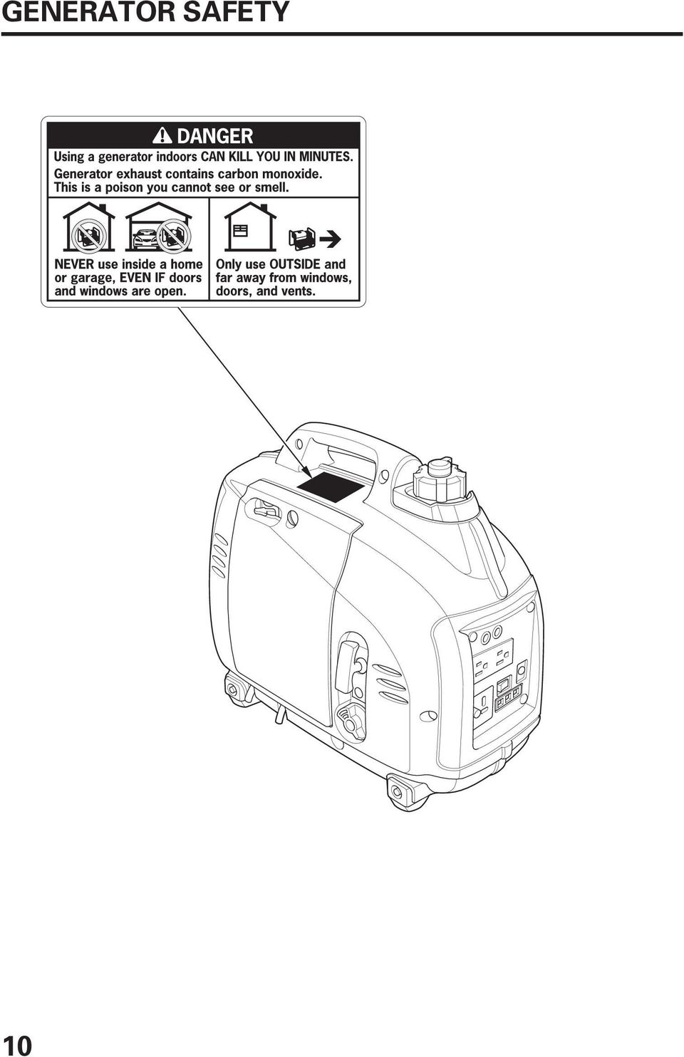
2 The engine exhaust from this product contains chemicals known to the State of California to cause cancer, birth defects or other reproductive harm. Exhaust contains poisonous carbon monoxide gas that can build up to dangerous levels in closed areas. Breathing carbon monoxide can cause unconsciousness or death. Never run the generator in a closed, or even partly closed area where people may be present. Keep this owner s manual handy so that you can refer to it at any time. This owner s manual is considered a permanent part of the generator and should remain with the generator if resold. The information and specifications included in this publication were in effect at the time of approval for printing. Honda Motor Co., Ltd. reserves the right, however, to discontinue or change specifications or design at any time without notice and without incurring any obligation whatever.

3 INTRODUCTION Congratulations on your selection of a Honda generator. We are certain you will be pleased with your purchase of one of the finest generators on the market. We want to help you get the best results from your new generator and to operate it safely. This manual contains all the information on how to do that; please read it carefully. As you read this manual, you will find information preceded by a symbol. That information is intended to help you avoid damage to your generator, other property, or the environment. We suggest you read the Distributor s Limited Warranty (see page 73 ) to fully understand its coverage and your responsibilities of ownership. When your generator needs scheduled maintenance, keep in mind that your Honda servicing dealer is specially trained in servicing Honda generators and is supported by the parts and service divisions of American Honda. Your Honda servicing dealer is dedicated to your satisfaction and will be pleased to answer your questions and concerns. Best Wishes, Honda Motor Co., Ltd. 1
 to fully understand its coverage and your responsibilities of ownership.")
4 A FEW WORDS ABOUT SAFETY Your safety and the safety of others are very important. And using this generator safely is an important responsibility. To help you make informed decisions about safety, we have provided operating procedures and other information on labels and in this manual. This information alerts you to potential hazards that could hurt you or others. Of course, it is not practical or possible to warn you about all the hazards associated with operating or maintaining a generator. You must use your own good judgement. You will find important safety information in a variety of forms, including: Safety Labels on the generator. Safety Messages preceded by a safety alert symbol of three signal words, DANGER, WARNING, or CAUTION. and one These signal words mean: You WILL be KILLED or SERIOUSLY HURT if you don t follow instructions. You CAN be KILLED or SERIOUSLY HURT if you don t follow instructions. You CAN be HURT if you don t follow instructions. Safety Headings such as IMPORTANT SAFETY INFORMATION. Safety Section such as GENERATOR SAFETY. Instructions how to use this generator correctly and safely. This entire book is filled with important safety information please read it carefully. 2

5 CONTENTS GENERATOR SAFETY...6 IMPORTANT SAFETY INFORMATION...6 Operator Responsibility...6 Carbon Monoxide Hazards...6 Electric Shock Hazards...7 Fire and Burn Hazards...7 Refuel With Care...8 SAFETY LABEL LOCATIONS...9 CONTROLS & FEATURES...11 COMPONENT & CONTROL LOCATIONS...11 CONTROLS...13 Engine Switch...13 Starter Grip...13 Fuel Tank Cap Vent Lever...14 Choke Lever...14 Eco-Throttle Switch...15 Parallel Operation Outlets...15 DC Receptacle...16 DC Circuit Protector...16 FEATURES...17 Output Indicator...17 Overload Indicator...17 Oil Alert Indicator...18 Ground Terminal...18 BEFORE OPERATION...19 ARE YOU READY TO GET STARTED?...19 Knowledge...19 IS YOUR GENERATOR READY TO GO?...19 Check the Engine

6 CONTENTS OPERATION...21 SAFE OPERATING PRECAUTIONS...21 STARTING THE ENGINE...22 STOPPING THE ENGINE...25 AC OPERATION...27 AC Applications...29 AC PARALLEL OPERATION...30 AC Parallel Operation Applications...32 DC OPERATION...34 ECO-THROTTLE SYSTEM...37 STANDBY POWER...38 Connections to a Building s Electrical System...38 System Ground...38 Special Requirements...39 SERVICING YOUR GENERATOR...40 THE IMPORTANCE OF MAINTENANCE...40 MAINTENANCE SAFETY...41 Safety Precautions...41 MAINTENANCE SCHEDULE...42 REFUELING...43 FUEL RECOMMENDATIONS...44 ENGINE OIL LEVEL CHECK...45 ENGINE OIL CHANGE...47 ENGINE OIL RECOMMENDATIONS...48 AIR CLEANER SERVICE...49 FOAM AIR FILTER CLEANING...50 SPARK PLUG SERVICE...51 SPARK ARRESTER SERVICE...53 STORAGE...55 STORAGE PREPARATION...55 Cleaning...55 Fuel...55 Engine Oil...58 STORAGE PRECAUTIONS...59 REMOVAL FROM STORAGE

7 CONTENTS TRANSPORTING...60 TAKING CARE OF UNEXPECTED PROBLEMS...61 ENGINE WILL NOT START...61 ENGINE LACKS POWER...62 NO POWER AT THE AC RECEPTACLES...63 NO POWER AT THE DC RECEPTACLE...63 TECHNICAL & CONSUMER INFORMATION...64 TECHNICAL INFORMATION...64 Serial Number Location...64 Carburetor Modification for High Altitude Operation...65 Emission Control System Information...66 Air Index...68 Specifications...69 Wiring Diagram...70 CONSUMER INFORMATION...71 Dealer Locator Information...71 Honda Publications...71 Customer Service Information...72 Distributor s Limited Warranty...73 Emission Control System Warranty...74 INITIAL USE INSTRUCTIONS...79 ENGINE OIL...79 FUEL...80 BEFORE OPERATION...82 INDEX...83 QUICK REFERENCE INFORMATION...Inside back cover 5

8 GENERATOR SAFETY IMPORTANT SAFETY INFORMATION Honda generators are designed for use with electrical equipment that has suitable power requirements. Other uses can result in injury to the operator or damage to the generator and other property. Most injuries or property damage can be prevented if you follow all instructions in this manual and on the generator. The most common hazards are discussed below, along with the best way to protect yourself and others. Operator Responsibility Know how to stop the generator quickly in case of emergency. Understand the use of all generator controls, output receptacles, and connections. Be sure that anyone who operates the generator receives proper instruction. Do not let children operate the generator without parental supervision. Carbon Monoxide Hazards Exhaust contains poisonous carbon monoxide, a colorless, odorless gas. Breathing carbon monoxide can cause loss of consciousness and may lead to death. If you run the generator in an area that is confined, or even partly enclosed area, the air you breathe could contain a dangerous amount of exhaust gas. Never run your generator inside a garage, house, or near open windows or doors. 6

9 GENERATOR SAFETY Electric Shock Hazards The generator produces enough electric power to cause a serious shock or electrocution if misused. Using a generator or electrical appliance in wet conditions, such as rain or snow, or near a pool or sprinkler system, or when your hands are wet, could result in electrocution. Keep the generator dry. If the generator is stored outdoors, unprotected from the weather, check all of the electrical components on the control panel before each use. Moisture or ice can cause a malfunction or short circuit in electrical components that could result in electrocution. Do not connect to a building s electrical system unless an isolation switch has been installed by a qualified electrician. Use only a Honda approved parallel operation cables (optional equipment) when connecting two EU1000i generators for parallel operation. Never connect different generator models. Fire and Burn Hazards The exhaust system gets hot enough to ignite some materials. Keep the generator at least 3 feet (1 meter) away from buildings and other equipment during operation. Do not enclose the generator in any structure. Keep flammable materials away from the generator. The muffler becomes very hot during operation and remains hot for a while after stopping the engine. Be careful not to touch the muffler while it is hot. Let the engine cool before storing the generator indoors. 7

10 GENERATOR SAFETY Refuel With Care Gasoline is extremely flammable, and gasoline vapor can explode. Allow the engine to cool if the generator has been in operation. Refuel only outdoors in a well-ventilated area with the engine OFF. Do not overfill the fuel tank. Never smoke near gasoline, and keep other flames and sparks away. Always store gasoline in an approved container. Make sure that any spilled fuel has been wiped up before starting the engine. 8

11 GENERATOR SAFETY SAFETY LABEL LOCATIONS These labels warn you of potential hazards that can cause serious injury. Read them carefully. If a label comes off or becomes hard to read, contact your Honda servicing dealer for a replacement. 9

12 GENERATOR SAFETY 10
13 CONTROLS & FEATURES COMPONENT & CONTROL LOCATIONS Use the illustrations on these pages to locate and identify the most frequently used controls. PARALLEL OPERATION OUTLETS AC RECEPTACLES ECO-THROTTLE SWITCH GROUND TERMINAL OIL ALERT INDICATOR OVERLOAD INDICATOR OUTPUT INDICATOR DC RECEPTACLE DC CIRCUIT PROTECTOR CHOKE LEVER FUEL TANK CAP VENT LEVER FUEL TANK CAP STARTER GRIP MAINTENANCE COVER ENGINE SWITCH 11

14 CONTROLS & FEATURES SPARK PLUG MAINTENANCE COVER SPARK PLUG MUFFLER 12

15 CONTROLS & FEATURES CONTROLS Engine Switch ENGINE SWITCH The engine switch controls the ignition system and the fuel valve. OFF Stops the engine and closes the fuel valve. ON ON Running position; opens the fuel valve and allows the engine to be started. Starter Grip OFF Pulling the starter grip operates the recoil starter to crank the engine. Do not allow the starter grip to snap back against the generator. Return it gently to prevent damage to the starter. STARTER GRIP 13

16 CONTROLS & FEATURES Fuel Tank Cap Vent Lever The fuel tank cap is provided with a vent lever to seal the fuel tank. The vent lever must be in the ON position for the engine to run. When the engine is not in use, leave the vent lever in the OFF position to reduce the possibility of fuel leakage. Allow the engine to cool well before turning the vent lever to the OFF position. FUEL TANK CAP FUEL TANK CAP VENT LEVER OFF ON Choke Lever The choke is used to provide proper starting mixture when the engine is cold. It can be opened and closed by operating the choke lever manually. Move the choke lever to the CLOSED position to enrich the mixture for cold starting. CHOKE LEVER OPEN CLOSED 14

17 CONTROLS & FEATURES Eco-Throttle TM Switch TM The Eco-Throttle system automatically reduces engine speed when loads are turned off or disconnected. When appliances are turned on or reconnected, the engine returns to the proper speed to power the electrical load. If high electrical loads are connected simultaneously, turn the Eco-Throttle switch to the OFF position to reduce voltage changes. ON: Recommended to minimize fuel consumption and further reduce noise levels when less than a full load is applied to the generator. OFF: The Eco-Throttle system does not operate. When using the DC output, turn the Eco-Throttle switch to the OFF position. ECO-THROTTLE SWITCH ON OFF Parallel Operation Outlets These outlets are used for connecting two EU1000i generators for parallel operation (see page 30). A Honda approved parallel operation cables (optional equipment) is required for parallel operation. This cable can be purchased from an authorized Honda generator dealer. PARALLEL OPERATION OUTLETS 15

18 CONTROLS & FEATURES DC Receptacle The DC receptacle should ONLY be used for charging 12-volt automotive type batteries. The DC charging output is not regulated. DC Circuit Protector The DC circuit protector automatically shuts off the DC battery charging circuit when the DC charging circuit is overloaded, when there is a problem with the battery, or when the connections between the battery and the generator are improper. However, the circuit protector does not prevent overcharging. OFF PUSH ON DC CIRCUIT PROTECTOR DC RECEPTACLE 16

19 CONTROLS & FEATURES Output Indicator The output indicator (green) is illuminated when the generator is operating normally. It indicates that the generator is producing electrical power at the receptacles. OUTPUT INDICATOR (GREEN) Overload Indicator If the generator is overloaded (in excess of 1.0 kva), or if there is a short circuit in a connected appliance, the overload indicator (red) will come ON. The overload indicator (red) will stay ON, and after about four seconds, current to the connected appliance(s) will shut off, and the output indicator (green) will go OFF. However, the engine will continue to run. OVERLOAD INDICATOR (RED) 17
, or if there is a short circuit in a connected appliance, the overload indicator (red) will come ON.")
20 CONTROLS & FEATURES Oil Alert Indicator The Oil Alert system is designed to prevent engine damage caused by an insufficient amount of oil in the crankcase. Before the oil level in the crankcase can fall below a safe limit, the Oil Alert indicator (red) comes on and the Oil Alert system automatically will stop the engine (the engine switch will remain in the ON position). If the engine stops or the Oil Alert indicator (red) comes on when you pull the starter grip, check the engine oil level (see page 45 ) before troubleshooting in other areas. OIL ALERT INDICATOR (RED) Ground Terminal The generator ground terminal is connected to the frame of the generator, the metal non-current-carrying parts of the generator, and the ground terminals of each receptacle. Before using the ground terminal, consult a qualified electrician, electrical inspector, or local agency having jurisdiction for local codes or ordinances that apply to the intended use of the generator. GROUND TERMINAL 18
 Ground Terminal The generator ground terminal is connected to the frame of the generator, the metal non-current-carrying parts of the generator, and the ground terminals of")
21 BEFORE OPERATION ARE YOU READY TO GET STARTED? Your safety is your responsibility. A little time spent in preparation will significantly reduce your risk of injury. Knowledge Read and understand this manual. Know what the controls do and how to operate them. Familiarize yourself with the generator and its operation before you begin using it. Know how to quickly shut off the generator in case of an emergency. If the generator is being used to power appliances, be sure that they do not exceed the generator s load rating (see pages 29 and 33 ). IS YOUR GENERATOR READY TO GO? For your safety, and to maximize the service life of your equipment, it is very important to take a few moments before you operate the generator to check its condition. Be sure to take care of any problem you find, or have your servicing dealer correct it, before you operate the generator. Improperly maintaining this generator, or failing to correct a problem before operation, could cause a malfunction in which you could be seriously injured. Always perform a pre-operation inspection before each operation, and correct any problem. 19
22 BEFORE OPERATION To prevent a possible fire, keep the generator at least 3 feet (1 meter) away from building walls and other equipment during operation. Do not place flammable objects close to the engine. Before beginning your pre-operation checks, be sure the generator is on a level surface and the engine switch is in the OFF position. Check the Engine Check the oil level (see page 45 ). A low oil level will cause the Oil Alert system to shut down the engine. Check the air filter (see page 49 ). A dirty air filter will restrict air flow to the carburetor, reducing engine and generator performance. Check the fuel level (see page 43 ). Starting with a full tank will help to eliminate or reduce operating interruptions for refueling. 20
23 OPERATION SAFE OPERATING PRECAUTIONS Before operating the generator for the first time, review chapters GENERATOR SAFETY (see page 6 ) and BEFORE OPERATION (see page 19 ). For your safety, do not operate the generator in an enclosed area such as a garage. Your generator s exhaust contains poisonous carbon monoxide gas that can collect rapidly in an enclosed area and cause illness or death. Exhaust contains poisonous carbon monoxide gas that can build up to dangerous levels in closed areas. Breathing carbon monoxide can cause unconsciousness or death. Never run the generator in a closed, or even partly closed area where people may be present. Before connecting an AC appliance or power cord to the generator: Use grounded 3-prong extension cords, tools, and appliances, or double-insulated tools and appliances. Inspect cords and plugs, and replace if damaged. Make sure that the appliance is in good working order. Faulty appliances or power cords can create a potential for electric shock. Make sure the electrical rating of the tool or appliance does not exceed that of the generator. Never exceed the maximum power rating of the generator. Power levels between rated and maximum may be used for no more than 30 minutes. Operate the generator at least 3 feet (1 meter) away from buildings and other equipment. Do not operate the generator in an enclosed structure. 21
24 OPERATION STARTING THE ENGINE To prevent a possible fire, keep the generator at least 3 feet (1 meter) away from building walls and other equipment during operation. Do not place flammable objects close to the engine. Operating this generator less than 3 feet (1 meter) from a building or other obstruction can cause overheating and damage the generator. For proper cooling, allow at least 3 feet (1 meter) of empty space above and around the generator. Refer to SAFE OPERATING PRECAUTIONS on page 21and perform the IS YOUR GENERATOR READY TO GO checks (see page 19 ). Refer to AC OPERATION (see page 27 ) or DC OPERATION (see page 34 ) for connecting loads to the generator. 1. Make sure that all appliances connected to the generator are turned off. The generator may be hard to start if a load is connected. 2. Turn the fuel tank cap vent lever to the ON position. FUEL TANK CAP VENT LEVER OFF ON 22
25 OPERATION 3. Make sure the Eco-Throttle switch is in the OFF position, or more time will be required for warm-up. ECO-THROTTLE SWITCH OFF 4. To start a cold engine, move the choke lever to the CLOSED position. To restart a warm engine, leave the choke lever in the OPEN position. OPEN CHOKE LEVER CLOSED 5. Turn the engine switch to the ON position. ON ENGINE SWITCH OFF 23
26 OPERATION 6. Pull the starter grip lightly until you feel resistance, then pull briskly in the direction of the arrow as shown. STARTER GRIP Do not allow the starter grip to snap back against the generator. Return it gently to prevent damage to the starter. Direction to pull 7. If the choke lever was moved to the CLOSED position to start the engine, gradually move it to the OPEN position as the engine warms up. CHOKE LEVER OPEN CLOSED 8. Ifyouwishtousethe Eco-Throttle system, turn the Eco-Throttle switch to the ON position after the engine has warmed up for 2 or 3 minutes. ECO-THROTTLE SWITCH ON 24
27 OPERATION STOPPING THE ENGINE To stop the engine in an emergency, simply turn the engine switch to the OFF position. Under normal conditions, use the following procedure. 1. Turn off or disconnect all appliances connected to the generator. 2. Turn the engine switch to the OFF position. ON ENGINE SWITCH OFF 3. Allow the engine to cool, and then turn the fuel tank cap vent lever to the OFF position. FUEL TANK CAP VENT LEVER OFF ON 25
28 OPERATION 4. If two generators were connected for parallel operation, disconnect the parallel operation cables after stopping the engines if you do not wish to resume parallel operation. PARALLEL OPERATION CABLES (optional equipment) 26
29 OPERATION AC OPERATION Before connecting an appliance to the generator, make sure that it is in good working order and that its electrical rating does not exceed that of the generator. Most motorized appliances require more than their electrical rating for startup. When an electric motor is started, the overload indicator (red) may come on. This is normal if the overload indicator (red) goes off within 4 seconds. If the overload indicator (red) stays on, consult your generator dealer. 1. Start the engine (see page 22 ) and make sure the output indicator (green) comes on. OUTPUT INDICATOR (GREEN) OVERLOAD INDICATOR (RED) 27
30 OPERATION 2. Plug in the appliance into the receptacle. 3. Turn on the appliance. If the generator is overloaded (see page 29 ), or if there is a short circuit in a connected appliance, the overload indicator (red) will go ON. The overload indicator (red) will stay ON, and after about four seconds, current to the connected appliance(s) will shut off, and the output indicator (green) will go OFF. Stop the engine and investigate the problem. Determine if the cause is a short circuit in a connected appliance or an overload. Correct the problem and restart the generator. 28
31 OPERATION AC Applications Before connecting an appliance or power cord to the generator: Make sure that it is in good working order. A faulty appliance or power cord can create a potential for electrical shock. If an appliance begins to operate abnormally, becomes sluggish, or stops suddenly, turn it off immediately. Disconnect the appliance, and determine whether the problem is the appliance or the rated load capacity of the generator has been exceeded. Make sure that the combined electrical rating of the tools or appliances do not exceed that of the generator. Never exceed the maximum power rating of the generator. Power levels between rated and maximum may be used for no more than 30 minutes. Substantial overloading will open the circuit protector. Exceeding the time limit for maximum power operation or slightly overloading the generator may not switch the circuit protector OFF, but will shorten the service life of the generator. Limit operation requiring maximum power to 30 minutes. Maximum power is: 1.0 kva For continuous operation, do not exceed the rated power. Rated power is: 0.9 kva The total power requirements (VA) of all appliances connected must be considered. Appliance and power tool manufacturers usually list rating information near the model number or serial number. 29
32 OPERATION AC PARALLEL OPERATION Before connecting an appliance to either generator, make sure that it is in good working order and that its electrical rating does not exceed that of the receptacle. Most motorized appliances require more than their electrical rating for startup. When an electric motor is started, the overload indicator (red) may come on. This is normal if the overload indicator (red) goes off within 4 seconds. If the overload indicator (red) stays on, consult your generator dealer. During parallel operation, the Eco-Throttle switch should be in the same position on both generators. 1. Connect the parallel operation cables (optional equipment) between the two EU1000i generators following the instructions supplied with the parallel operation cables. PARALLEL OPERATION CABLES (optional equipment) 2. Start the engines (see page 22 ) and make sure the output indicator (green) on each generator comes on (see page 27 ). 30
33 OPERATION 3. Plug in the appliance following the instruction provided with the parallel operation cables. 4. Turn on the appliance. If the generators are overloaded (see page 33 ), or if there is a short circuit in a connected appliance, the overload indicator (red) will go ON. The overload indicator (red) will stay ON, and after about four seconds, current to the connected appliance(s) will shut off, and the output indicator (green) will go OFF. Stop both engines and investigate the problem. Determine if the cause is a short circuit in a connected appliance or an overload. Correct the problem and restart the generator. 31
34 OPERATION AC Parallel Operation Applications Follow the instructions included with the parallel operation cables. Before connecting an appliance or power cord to the generator: Make sure that it is in good working order. A faulty appliance or power cord can create a potential for electrical shock. If an appliance begins to operate abnormally, becomes sluggish, or stops suddenly, turn it off immediately. Disconnect the appliance, and determine whether the problem is the appliance or the rated load capacity of the generator has been exceeded. Make sure that the combined electrical rating of the tools or appliances do not exceed that of the generator. Never exceed the maximum power rating of the generator. Power levels between rated and maximum may be used for no more than 30 minutes. Never connect different generator models. Use only a Honda approved parallel operation cables (optional equipment, see page 71 ) when connecting two EU1000i generators for parallel operation. Never connect or remove the parallel operation cables when the generator is running. For single generator operation, the parallel operation cables must be removed. Substantial overloading that continuously lights the overload indicator (red) may damage the generator. Marginal overloading that temporarily lights the overload indicator (red) may shorten the service life of the generator. 32
35 Limit operation requiring maximum power to 30 minutes. Maximum power in parallel operation is: 2.0 kva For continuous operation, do not exceed the rated power. Rated power in parallel operation is: 1.8 kva OPERATION The total power requirements (VA) of all appliances connected must be considered. Appliance and power tool manufacturers usually list rating information near the model number or serial number. 33
36 OPERATION DC OPERATION The DC receptacle should ONLY be used for charging 12-volt automotive type batteries. The DC charging output is not regulated. When using the DC output, turn the Eco-Throttle switch to the OFF position. Connecting the battery charging cable (optional equipment): 1. Before connecting the battery charging cable to a battery that is installed in a vehicle, disconnect the vehicle battery ground cable from the negative ( ) battery terminal. The battery gives off explosive hydrogen gas during normal operation. A spark or flame can cause the battery to explode with enough force to kill or seriously hurt you. Wear protective clothing and a face shield, or have a skilled mechanic perform the battery maintenance. WARNING: Battery posts, terminals, and related accessories contain lead and lead components. Wash hands after handling. 2. Plug the battery charging cable into the DC receptacle of the generator. BATTERY CHARGING CABLE (optional equipment) BLACK LEAD RED LEAD 34
37 OPERATION 3. Connect the red lead of the battery charging cable to the positive ( ) battery terminal and the black lead to the negative ( ) battery terminal. OFF PUSH ON DC CIRCUIT PROTECTOR DC RECEPTACLE 4. Start the generator (see page 22 ). Do not start the vehicle while the battery charging cable is connected and the generator is running. The vehicle or the generator may be damaged. An overloaded DC circuit, excessive current draw by the battery, or a wiring problem will trip the DC circuit protector (PUSH button extends out). If this happens, wait a few minutes before pushing in the circuit protector to resume operation. If the DC circuit protector continues to go OFF, discontinue charging and see your authorized Honda generator dealer. The circuit protector does not prevent overcharging the battery. 35
38 OPERATION Disconnecting the battery charging cable (optional equipment): 1. Stop the engine. 2. Disconnect the black lead of the battery charging cable from the negative ( ) battery terminal. 3. Disconnect the red lead of the battery charging cable from the positive ( ) battery terminal. 4. Disconnect the battery charging cable from the DC receptacle of the generator. 5. Connect the vehicle battery ground cable to the negative ( ) battery terminal. BATTERY CHARGING CABLE (optional equipment) BLACK LEAD RED LEAD 36
39 OPERATION ECO-THROTTLE TM SYSTEM With the switch in the ON position, engine speed is automatically lowered when loads are reduced, turned OFF, or disconnected. When appliances are turned ON or reconnected, the engine returns to the proper speed to power the electrical load. In the OFF position, the Eco-Throttle system does not operate. Appliances with large start-up power demands may not allow the engine to reach normal operating rpm when they are connected to the generator. Turn the Eco-Throttle to the OFF position and connect the appliance to the generator. If the engine still will not reach normal operating speed, check that the appliance does not exceed the rated load capacity of the generator. If high electrical loads are connected simultaneously, turn the Eco-Throttle switch to the OFF position to reduce voltage changes. The Eco-Throttle system is not effective for use with appliances or tools that require only momentary power. If the tool or appliance will be turned ON and OFF quickly, the Eco-Throttle switch should be in the OFF position. When using the DC output, turn the Eco-Throttle switch to the OFF position. ECO-THROTTLE SWITCH ON OFF 37
40 OPERATION STANDBY POWER Connections to a Building s Electrical System Connections for standby power to a building s electrical system must be made by a qualified electrician. The connection must isolate the generator power from utility power, and must comply with all applicable laws and electrical codes. Improper connections to a building s electrical system can allow current from the generator to backfeed into the utility lines. Such backfeed may electrocute utility company workers or others who contact the lines during a power outage, and the generator may explode, burn, or cause fires when utility power is restored. Consult the utility company or a qualified electrician prior to making any power connections. In some areas, generators are required by law to be registered with local utility companies. Check local regulations for proper registration and use procedures. System Ground Honda portable generators have a system ground that connects the generator frame components to the ground terminals in the AC output receptacles. The system ground is not connected to the AC neutral wire. If the generator is tested with a receptacle tester, it will not show the same ground circuit condition as for a home receptacle. 38
41 OPERATION Special Requirements Keep all cooling holes open and clear of debris, mud, water, etc. Cooling holes are located on the side panel, the control panel, and the bottom of the generator. If the cooling holes are blocked, the generator may overheat and damage the engine, inverter, or windings. Do not lay the generator on its side when moving, storing, or operating it. Oil may leak and damage the engine or your property. There may be Federal or State Occupational Safety and Health Administration (OSHA) regulations, local codes, or ordinances that apply to the intended use of the generator. Please consult a qualified electrician, electrical inspector, or the local agency having jurisdiction. In some areas, generators are required to be registered with local utility companies. If the generator is used at a construction site, there may be additional regulations that must be observed. 39
42 SERVICING YOUR GENERATOR THE IMPORTANCE OF MAINTENANCE Good maintenance is essential for safe, economical, and trouble free operation. It will also help reduce air pollution. To help you properly care for your generator, the following pages include a maintenance schedule, routine inspection procedures, and simple maintenance procedures using basic hand tools. Other service tasks that are more difficult or require special tools are best handled by professionals and are normally performed by a Honda technician or other qualified mechanic. The maintenance schedule applies to normal operating conditions. If you operate your generator under unusual conditions, such as sustained high-load or high-temperature operation, or use it in dusty conditions, consult your servicing dealer for recommendations applicable to your individual needs and use. Improper maintenance, or failure to correct a problem before operation, can cause a malfunction in which you can be seriously hurt or killed. Always follow the inspection and maintenance recommendations and schedules in this owner s manual. Remember that your servicing dealer knows your generator best and is fully equipped to maintain and repair it. To ensure the best quality and reliability, use only new, Honda Genuine parts or their equivalents for repair and replacement. Maintenance, replacement, or repair of the emission control devices and systems may be performed by any engine repair establishment or individual, using parts that are certified to EPA standards. 40
43 SERVICING YOUR GENERATOR MAINTENANCE SAFETY Some of the most important safety precautions follow. However, we cannot warn you of every conceivable hazard that can arise in performing maintenance. Only you can decide whether or not you should perform a given task. Failure to properly follow maintenance instructions and precautions can cause you to be seriously hurt or killed. Always follow the procedures and precautions in the owner s manual. Safety Precautions Make sure the engine is off before you begin any maintenance or repairs. This will eliminate several potential hazards: Carbon monoxide poisoning from engine exhaust. Operate outside away from open windows or doors. Burns from hot parts. Let the engine and exhaust system cool before touching. Injury from moving parts. Do not run the engine unless instructed to do so. Read the instructions before you begin, and make sure you have the tools and skills required. To reduce the possibility of fire or explosion, be careful when working around gasoline. Use only a non-flammable solvent, not gasoline, to clean parts. Keep cigarettes, sparks, and flames away from all fuel-related parts. 41
44 SERVICING YOUR GENERATOR MAINTENANCE SCHEDULE REGULAR SERVICE PERIOD (3) Perform at every indicated month or operating hour interval, whichever comes first. ITEM Engine oil Check level Change Air cleaner Check Clean Spark plug Check-adjust Replace Spark arrester Valve clearance Combustion chamber Fuel tank and filter Fuel tube Clean Check-adjust Clean Clean Check Each use First month or 10 Hrs. Every 3 months or 50 Hrs. (1) Every 6 months or 100 Hrs. Every 2 years or 300 Hrs. (2) After every 300 hrs. (2) Every year (2) Every 2 years (Replace if necessary) (2) Page (1) Service more frequently when used in dusty areas. (2) These items should be serviced by your Honda servicing dealer, unless you have the proper tools and are mechanically proficient. Refer to the Honda shop manual for service procedures. (3) For commercial use, log hours of operation to determine proper maintenance intervals. Failure to follow this maintenance schedule could result in non-warrantable failures. 42
45 SERVICING YOUR GENERATOR REFUELING With the engine stopped, remove the fuel tank cap and check the fuel level. Refill the fuel tank if the fuel level is low. Gasoline is highly flammable and explosive. You can be burned or seriously injured when handling fuel. Stop the engine and keep heat, sparks, and flame away. Handle fuel only outdoors. Wipe up spills immediately. Fuel can damage paint and plastic. Be careful not to spill fuel when filling your fuel tank. Damage caused by spilled fuel is not covered under warranty. Refuel in a well-ventilated area before starting the engine. If the engine has been running, allow it to cool. Refuel carefully to avoid spilling fuel. Do not fill above the upper level mark. Never refuel the engine inside a building where gasoline fumes may reach flames or sparks. Keep gasoline away from appliance pilot lights, barbecues, electric appliances, power tools, etc. Spilled fuel is not only a fire hazard, it causes environmental damage. Wipe up spills immediately. FUEL TANK CAP UPPER LEVEL MARK After refueling, reinstall the fuel tank cap securely. 43
46 SERVICING YOUR GENERATOR FUEL RECOMMENDATIONS This engine is certified to operate on regular unleaded gasoline with a pump octane rating of 86 or higher. Never use stale or contaminated gasoline or an oil/gasoline mixture. Avoid getting dirt or water in the fuel tank. You may use regular unleaded gasoline containing no more than 10% ethanol (E10) or 5% methanol by volume. In addition, methanol must contain cosolvents and corrosion inhibitors. Use of fuels with content of ethanol or methanol greater than shown above may cause starting and/or performance problems. It may also damage metal, rubber, and plastic parts of the fuel system. Engine damage or performance problems that result from using a fuel with percentages of ethanol or methanol greater than shown above are not covered under warranty. If your equipment will be used on an infrequent basis, please refer to the fuel section of the STORAGE chapter (see page 55 ) for additional information regarding fuel deterioration. 44
47 SERVICING YOUR GENERATOR ENGINE OIL LEVEL CHECK Check the engine oil level with the generator on a level surface and the engine stopped. 1. Loosen the cover screw and remove the maintenance cover. COVER SCREW MAINTENANCE COVER 45
48 SERVICING YOUR GENERATOR 2. Remove the oil filler cap and wipe the dipstick clean. 3. Check the oil level by inserting the dipstick into the oil filler neck without screwing it in. 4. If the level is low, fill to the upper limit of the oil filler neck with the recommended oil (see page 48 ). 5. Reinstall the maintenance cover and tighten the cover screw securely. DIPSTICK UPPER LIMIT OIL FILLER CAP The Oil Alert system will automatically stop the engine before the oil level falls below safe limits. However, to avoid the inconvenience of an unexpected shutdown, check the oil level regularly. 46
49 SERVICING YOUR GENERATOR ENGINE OIL CHANGE Drain the oil while the engine is warm to assure rapid and complete draining. 1. Turn the engine switch and fuel tank cap vent lever to the OFF position (see page 25 ) to reduce the possibility of fuel leakage. 2. Loosen the cover screw and remove the maintenance cover (see page 45 ). 3. Place a suitable container next to the engine to catch the used oil. 4. Remove the oil filler cap/dipstick, and drain the oil into the container by tipping the engine toward the oil filler neck. Improper disposal of engine oil can be harmful to the environment. If you change your own oil, please dispose of the used oil properly. Put it in a sealed container, and take it to a recycling center. Do not discard it in a trash bin, dump it on the ground, or pour it down the drain. 5. With the engine in a level position, fill to the upper limit of the oil filler neck with the recommended oil (see page 48). 6. Reinstall the oil filler cap/dipstick securely. 7. Reinstall the maintenance cover and tighten the cover screw securely. Wash your hands with soap and water after handling used oil. OIL FILLER NECK UPPER LIMIT 47
50 SERVICING YOUR GENERATOR ENGINE OIL RECOMMENDATIONS Oil is a major factor affecting performance and service life. Use 4-stroke automotive detergent oil. SAE 10W 30 is recommended for general use. Other viscosities shown in the chart may be used when the average temperature in your area is within the recommended range. AMBIENT TEMPERATURE The SAE oil viscosity and service category are in the API label on the oil container. Honda recommends that you use API service category SJ or later (or equivalent) oil. 48
51 SERVICING YOUR GENERATOR AIR CLEANER SERVICE COVER SCREW 1. Loosen the cover screw and remove the maintenance cover. 2. Press the latch tab on the top of the air cleaner case, and remove the air cleaner cover. 3. Check the foam air filter to be sure it is clean and in good condition. If the foam air filter is dirty, clean it as described on page 50. Replace the foam air filter if it is damaged. 4. Reinstall the air filter. 5. Make sure that the rubber seal is set in the groove of the air cleaner cover. MAINTENANCE COVER AIR CLEANER CASE FOAM AIR FILTER 6. Reinstall the air cleaner cover by inserting the lower tab and the latch tab. 7. Reinstall the maintenance cover, and tighten the cover screw securely. AIR CLEANER COVER RUBBER AIR GUIDE RUBBER SEAL Operating the engine without an air filter or with a damaged air filter will allow dirt to enter the engine, causing rapid engine wear. This type of damage is not covered by the Distributor s Limited Warranty. 49
52 SERVICING YOUR GENERATOR FOAM AIR FILTER CLEANING A dirty foam air filter will restrict air flow to the carburetor, reducing engine performance. If you operate the generator in very dusty areas, clean the foam air filter more frequently than specified in the Maintenance Schedule (see page 42 ). 1. Wash the foam air filter in a solution of household detergent and warm water, then rinse thoroughly, or wash in non-flammable or high flash point solvent. Allow the foam air filter to dry thoroughly. 2. Soak the foam air filter in clean engine oil and squeeze out the excess oil. The engine will smoke during initial startup if too much oil is left in the foam air filter. 1. Soak 2. Squeeze to Dry 3. Oil Do not twist. 4. Squeeze Do not twist. 3. Remove the rubber air guide from the air cleaner case. Clean the rubber air guide and the air cleaner case with a moist rag, then reinstall the rubber air guide. 50
53 SERVICING YOUR GENERATOR SPARK PLUG SERVICE In order to service the spark plug, you will need a spark plug wrench (commercially available). Recommended spark plug: CR5HSB (NGK) U16FSR-UB (DENSO) To ensure proper engine operation, the spark plug must be properly gapped and free of deposits. An incorrect spark plug can cause engine damage. If the engine is hot, allow it to cool before servicing the spark plug. 1. Remove the spark plug maintenance cover. 2. Remove the spark plug cap. SPARK PLUG MAINTENANCE COVER SPARK PLUG CAP 3. Clean any dirt from around the spark plug base. 4. Use a spark plug wrench to remove the spark plug. PLUG WRENCH 51
54 SERVICING YOUR GENERATOR 5. Inspect the spark plug. Replace it if the electrodes are worn or if the insulator is cracked, chipped, or fouled. 6. Measure the spark plug electrode gap with a wire-type feeler gauge. Correct the gap, if necessary, by carefully bending thesideelectrode. SIDE ELECTRODE SEALING WASHER in ( mm) The gap should be: in ( mm) 7. Make sure that the spark plug sealing washer is in good condition, and thread the spark plug in by hand to prevent cross-threading. 8. After the spark plug is seated, tighten with a spark plug wrench to compress the sealing washer. If reinstalling a used spark plug, tighten 1/8 1/4 turn after the spark plug seats. If installing a new spark plug, tighten 1/2 turn after the spark plug seats. A loose spark plug can overheat and damage the engine. Overtightening the spark plug can damage the threads in the cylinder head. 9. Reinstall the spark plug cap on the spark plug securely. 10. Reinstall the spark plug maintenance cover. 52
55 SPARK ARRESTER SERVICE SERVICING YOUR GENERATOR The spark arrester must be serviced every 100 hours to keep it functioning as designed. If the engine has been running, the muffler will be very hot. Allow the muffler to cool before servicing the spark arrester. Clean the spark arrester as follows: 1. Remove the four 5 mm screws, and remove the muffler protector. MUFFLER PROTECTOR 5 mm SCREWS 2. Remove the three 6 mm bolts, and remove the muffler, the spark arrester, and the muffler gasket. SPARK ARRESTER MUFFLER GASKET MUFFLER 6mmBOLTS 53
56 SERVICING YOUR GENERATOR 3. Use a brush to remove carbon deposits from the spark arrester screen. Be careful to avoid damaging the screen. The spark arrester must be free of breaks and tears. Replace the spark arrester if it is damaged. 4. Check the muffler gasket; replace if damaged. Reinstall the muffler gasket, the spark arrester, the muffler and the muffler protector in the reverse order of removal. 54
57 STORAGE STORAGE PREPARATION Proper storage preparation is essential for keeping your generator trouble-free and looking good. The following steps will help to keep rust and corrosion from impairing your generator s function and appearance, and will make the engine easier to start when you use the generator again. Cleaning Wipe the generator with a moist cloth. After the generator has dried, touch up any damaged paint, and coat other areas that may rust with a light film of oil. Fuel Depending on the region where you operate your equipment, fuel formulations may deteriorate and oxidize rapidly. Fuel deterioration and oxidation can occur in as little as 30 days and may cause damage to the carburetor and/or fuel system. Please check with your servicing dealer for local storage recommendations. Gasoline will oxidize and deteriorate in storage. Old gasoline will cause hard starting, and it leaves gum deposits that clog the fuel system. If the gasoline in your generator deteriorates during storage, you may need to have the carburetor and other fuel system components serviced or replaced. The length of time that gasoline can be left in your fuel tank and carburetor without causing functional problems will vary with such factors as gasoline blend, your storage temperatures, and whether the fuel tank is partially or completely filled. The air in a partially filled fuel tank promotes fuel deterioration. Very warm storage temperatures accelerate fuel deterioration. Fuel deterioration problems may occur within a few months, or even less if the gasoline was not fresh when you filled the fuel tank. The Distributor s Limited Warranty does not cover fuel system damage or engine performance problems resulting from neglected storage preparation. You can extend fuel storage life by adding a gasoline stabilizer that is formulated for that purpose, or you can avoid fuel deterioration problems by draining the fuel tank and carburetor. 55
58 STORAGE Adding a Gasoline Stabilizer to Extend Fuel Storage Life When adding a gasoline stabilizer, fill the fuel tank with fresh gasoline. If only partially filled, air in the tank will promote fuel deterioration during storage. If you keep a container of gasoline for refueling, be sure that it contains only fresh gasoline. 1. Add gasoline stabilizer following the manufacturer s instructions. 2. After adding a gasoline stabilizer, run the engine outdoors for 10 minutes to be sure that treated gasoline has replaced the untreated gasoline in the carburetor. 3. Turn the engine switch to the OFF position, and turn the fuel tank cap vent lever to the OFF position (see page 25 ). 56
59 STORAGE Draining the Fuel Tank and Carburetor Gasoline is highly flammable and explosive. You can be burned or seriously injured when handling fuel. Stop the engine and keep heat, sparks, and flame away. Handle fuel only outdoors. Wipe up spills immediately. 1. Unscrew the fuel tank cap (see page 43), remove the debris screen, and empty the fuel tank into an approved gasoline container. We recommend using a commercially available gasoline hand pump to empty the tank. Do not use an electric pump. Reinstall the debris screen and the fuel tank cap. 2. Loosen the cover screw and remove the side maintenance cover (see page 45). 3. Loosen the carburetor drain screw. 4. Drain the gasoline from the carburetor into a suitable container. 5. Remove the spark plug maintenance cover (see page 51). 6. Remove the spark plug cap. 7. Turn the engine switch to the ON position (see page 23). 8. Pull the starter grip (see page 24) 3 to 4 times to drain the gasoline from the fuel pump into a suitable container. 9. Turn the engine switch to the OFF position. 10. Tighten the carburetor drain screw. DRAIN SCREW DEBRIS SCREEN 57
60 STORAGE Engine Oil 1. Change the engine oil (see page 47). 2. Remove the spark plug (see page 51), and apply a couple of drops of clean engine oil into the cylinder. Crank the engine several revolutions to distribute the oil, then reinstall the spark plug. 3. Reinstall the spark plug cap on the spark plug securely. 4. Reinstall the spark plug maintenance cover. 5. Reinstall the maintenance cover and tighten the cover screw securely. 6. Pull the starter grip (see page 24) slowly until you feel resistance, then return the starter grip gently. This closes the valves so moisture cannot enter. 58
61 STORAGE STORAGE PRECAUTIONS If your generator will be stored with gasoline in the fuel tank and carburetor, it is important to reduce the hazard of gasoline vapor ignition. Select a well ventilated storage area away from any appliance that operates with a flame, such as a furnace, water heater, or clothes dryer. Also avoid any area with a spark-producing electric motor, or where power tools are operated. If possible, avoid storage areas with high humidity, because that promotes rust and corrosion. Unless all fuel has been drained from the fuel tank, leave the engine switch in the OFF position, and the fuel tank cap vent lever in the OFF position (see page 25 ) to reduce the possibility of leakage. Place the generator on a level surface. Tilting or laying it on its side can cause fuel or oil leakage. With the engine and exhaust system cool, cover the generator to keep out dust. A hot engine and exhaust system can ignite or melt some materials. Do not use sheet plastic as a dust cover. A nonporous cover will trap moisture around the generator, promoting rust and corrosion. REMOVAL FROM STORAGE Check your generator as described in the BEFORE OPERATION chapter of this manual (see page 19 ). If the fuel was drained during storage preparation, fill the tank with fresh gasoline. If you keep a container of gasoline for refueling, be sure that it contains only fresh gasoline. Gasoline oxidizes and deteriorates over time, causing hard starting. If the cylinder was coated with oil during storage preparation, the engine may smoke briefly at startup. This is normal. 59
62 TRANSPORTING Do not lay the generator on its side when moving, storing, or operating it. Oil may leak and damage the engine or your property. If the generator has been used, allow it cool for at least 15 minutes before loading the generator on the transport vehicle. A hot engine and exhaust system can burn you and can ignite some material. To prevent fuel spillage when transporting, the generator should be secured upright in its normal operating position, with the engine switch OFF and the fuel tank cap vent lever turned fully counterclockwise to the OFF position (see page 25 ). Take care not to drop or strike the generator when transporting. Do not place heavy objects on the generator. 60
The engine exhaust from this product contains chemicals known to the State of California to cause cancer, birth defects or other reproductive harm.
 o The engine exhaust from this product contains chemicals known to the State of California to cause cancer, birth defects or other reproductive harm. Exhaust contains poisonous carbon monoxide gas that
Owner s Manual. GENERATOR EU3000is. o2001-2012 Honda Motor Co., Ltd. -All Rights Reserved. See page 89 for Initial Use Instructions
 Owner s Manual GENERATOR EU3000is o2001-2012 Honda Motor Co., Ltd. -All Rights Reserved See page 89 for Initial Use Instructions The engine exhaust from this product contains chemicals known to the State
Owner s Manual GENERATOR EG4000CL EG5000CL EG6500CL. 2011 Honda Motor Co., Ltd. All Rights Reserved. See page 67 for Initial Use Instructions
 Owner s Manual GENERATOR EG4000CL EG5000CL EG6500CL 2011 Honda Motor Co., Ltd. All Rights Reserved See page 67 for Initial Use Instructions The engine exhaust from this product contains chemicals known
The engine exhaust from this product contains chemicals known to the State of California to cause cancer, birth defects or other reproductive harm.
 The engine exhaust from this product contains chemicals known to the State of California to cause cancer, birth defects or other reproductive harm. Exhaust contains poisonous carbon monoxide gas that can
Operator s Manual. PUMP Model: PAC25 SAVE THIS MANUAL FOR FUTURE REFERENCE. Distributed by: Pacer Pumps
 Operator s Manual PUMP Model: PAC25 CAUTION: Before using this product, read this manual and follow all Safety Rules and Operating Instructions. SAVE THIS MANUAL FOR FUTURE REFERENCE Distributed by: Pacer
EM3800SX EM5000SX EM6500SX
 EM3800SX EM5000SX EM6500SX See page 57 for instructions on assembling your generator. The engine exhaust from this product contains chemicals known to the State of California to cause cancer, birth defects
INVERTER GENERATOR OWNER S MANUAL FOR YOUR SAFETY PLEASE READ THESE INSTRUCTIONS CAREFULLY AND RETAIN THEM FOR FUTURE USE.
 INVERTER GENERATOR OWNER S MANUAL FOR YOUR SAFETY PLEASE READ THESE INSTRUCTIONS CAREFULLY AND RETAIN THEM FOR FUTURE USE. GENERATOR SAFETY EXHAUST GAS PRECAUTIONS Only use outdoors! Exhaust fumes can
NOTE: Gives helpful information. If a problem should arise, or if you have any questions about the generator, consult an authorized Honda dealer.
 Thank you for purchasing a Honda generator. This manual covers operation and maintenance of the EX800 generator. All information in this publication is based on the latest product information available
CARING FOR YOUR WATER HEATER
 http://waterheatertimer.org/troubleshoot-rheem-tankless-water-heater.html Water Heater Inspections CARING FOR YOUR WATER HEATER Venting System (Direct Vent Only) The venting system should be inspected
SV710-SV740. SV810-SV840 Owner's Manual
 SV710-SV740 SV810-SV840 Owner's Manual IMPORTANT: Read all safety precautions and instructions carefully before operating equipment. Refer to operating instruction of equipment that this engine powers.
3620 W 11th Streetб Houston, TX 77008 Telephone: 713-635-6291 Email: sales@kellogg-american.com Website: www.kellogg-american.com
 Unpackaging & Handling Be sure to carefully inspect the unit before accepting the shipment. If any damage has occurred document it with the trucking company immediately. Contact your Kellogg Distributor
GENERATOR MODEL NO: FG3050 OPERATION & MAINTENANCE INSTRUCTIONS PART NO: 8857705 LS0310
 GENERATOR MODEL NO: FG3050 PART NO: 8857705 OPERATION & MAINTENANCE INSTRUCTIONS LS0310 INTRODUCTION Thank you for purchasing this CLARKE Generator. Before attempting to use this product, please read this
Owner s Manual. Generator EM500 EM600 I I III I I!!
 Owner s Manual Generator EM500 EM600 Q1997 American Honda Motor Co., Inc. - All Rights Reserved I I III I I!! I Thank you for purchasing a Honda generator. This manual covers operation and maintenance
Installation Instructions for Alarm Module Kit A043F059
 Instruction Sheet 07-2013 Installation Instructions for Alarm Module Kit A043F059 1 Introduction The information contained within is based on information available at the time of going to print. In line
Click SAVE to save this manual to your computer. Thank you for choosing Honda.
 Click SAVE to save this manual to your computer. Thank you for choosing Honda. OWNER S MANUAL GC160 2000, 2001 American Honda Motor Co., Inc. All Rights Reserved 1 31ZL8A03 00X31-ZL8-A030 CONTENTS INTRODUCTION............3
National- Spencer Inc.
 9-27-2010 National- Spencer Inc. 19.2V HEAVY DUTY GREASE GUN PRODUCT SPECIFICATION Charger Input Power 110 VAC Battery Output Power 19.2V Battery Capacity 1500 MAH Battery Pack Charge Time 1 Hour Maximum
INTRODUCTION SAFETY MESSAGES CONTENTS OWNER S MANUAL HRX217VKA B WARNING: B WARNING CAUTION EM5
 INTRODUCTION Congratulations on your selection of a Honda lawn mower! We are certain you will be pleased with your purchase of one of the finest lawn mowers on the market. We want to help you get the best
Owner s Manual GX270 GX390 LPG-Fueled Engine
 Owner s Manual GX270 GX390 LPG-Fueled Engine 2003 Honda Motor Co., Ltd. -All Rights Reserved The engine exhaust from this product contains chemicals known to the State of California to cause cancer, birth
3 WATT LED SPOTLIGHT Model No. SLM - 3801
 3 WATT LED SPOTLIGHT Model No. SLM - 3801 OWNER'S MANUAL Customer Service Tel: 1-800-268-3319 Superex Canada Ltd, Toronto,M2H 3B8 Made in China Table of Contents A). Important Safety Instructions B). Charging
OPERATOR S MANUAL 18 VOLT, 1 HOUR CHARGER
 OPERATOR S MANUAL 18 VOLT, 1 HOUR CHARGER P110 Your battery charger has been engineered and manufactured to Ryobi s high standard for dependability, ease of operation, and operator safety. When properly
San josé OWNER S MANUAL
 San josé OWNER S MANUAL Assembling & operating manual San josé 30 mbar - PORTABLE GAS BARBECUE 1. 2. 3. Improper installation, adjustment, alteration, service or maintenance can injury or property damage.
NewAir AC-10000E, AC-10000H Portable Air Conditioner Owner s Manual PLEASE READ AND SAVE THESE INSTRUCTIONS
 NewAir AC-10000E, AC-10000H Portable Air Conditioner Owner s Manual PLEASE READ AND SAVE THESE INSTRUCTIONS BEFORE USE GENERAL SAFETY INSTRUCTIONS: ALWAYS OPERATE THE UNIT IN AN UPRIGHT POSITION AND PLACE
Trouble Shooting. Pump
 Trouble Shooting Pump Trouble Possible Cause Remedy Oil leaking in the area of water pump crankshaft Worn crankshaft seal, bad bearing, grooved shaft, or failure of retainer o-ring. Excessive play on crankshaft
400 Amp Rechargeable Jump Start System RAC-HP082
 400 Amp Rechargeable Jump Start System RAC-HP082 MAINTENANCE Always inspect the tool before use to ensure the cables are in good condition and the clamps are clean and free from corrosion. Keep clean by
Dehumidifier Users manual. For Models: DH45S DH65S
 Dehumidifier Users manual For Models: DH45S DH65S 950-0062-revD Jan. 9 2007 FORWARD The appearance of the units that you purchase might be slightly different from the ones described in the Manual, but
accidents which arise due to nonobservance and the safety information herein.
 20 GALLON COMPRESSOR Model: 7342 CALIFORNIA PROPOSITION 65 WARNING: You can create dust when you cut, sand, drill or grind materials such as wood, paint, metal, concrete, cement, or other masonry. This
Owner, s Manual SNOWBLOWER HS928 HS1332. C 2011 Honda Motor Co., Ltd. -All Rights Reserved
 Owner, s Manual SNOWBLOWER HS928 HS1332 C 2011 Honda Motor Co., Ltd. -All Rights Reserved The engine exhaust from this product contains chemicals known to the State of California to cause cancer, birth
The engine exhaust from this product contains chemicals known to the State of California to cause cancer, birth defects or other reproductive harm.
 The engine exhaust from this product contains chemicals known to the State of California to cause cancer, birth defects or other reproductive harm. Keep this owner s manual handy, so you can refer to it
Voltmaster Trash Pumps Model TSP2, TSP3 and TSP4
 Model TSP2, TSP3 and TSP4 Owner s Manual July 2010 Table of Contents 1 Introduction...................................................... 1 1.1 Read before using..............................................
INSTRUCTION MANUAL REFRIGERATOR BEFORE USE, PLEASE READ AND FOLLOW ALL SAFETY RULES AND OPERATING INSTRUCTIONS.
 INSTRUCTION MANUAL Model Number: BC-130 REFRIGERATOR BEFORE USE, PLEASE READ AND FOLLOW ALL SAFETY RULES AND OPERATING INSTRUCTIONS. 1 REFRIGERATOR SAFETY Your safety and the safety of others are very
Portable Evaporative Air Cooler. OWNER S MANUAL Read and save these instructions before use. Model: CL30XC
 Portable Evaporative Air Cooler OWNER S MANUAL Read and save these instructions before use Model: CL30XC Power rating: 250 Watts Voltage rating: 230 Volt, 50Hz Made in P.R.C. QUICK START GUIDE Fill with
15GAL STEEL OIL DRAIN WITH 110V PUMP
 15GAL STEEL OIL DRAIN WITH 110V PUMP OWNER S MANUAL WARNING: Read carefully and understand all ASSEMBLY AND OPERATION INSTRUCTIONS before operating. Failure to follow the safety rules and other basic safety
Ewm Indicates a strong possibility of severe personal injury or loss of
 Thank you for purchasing a Honda engine. This manual covers the operation and maintenance of GXV120 and GXVl60 engines. All information in this publication is based on the latest product information available
12 Volt 30 Amp Digital Solar Charge Controller
 12 Volt 30 Amp Digital Solar Charge Controller User s Manual WARNING Read carefully and understand all INSTRUCTIONS before operating. Failure to follow the safety rules and other basic safety precautions
MODEL 4750 223 cc Generator
 MODEL 4750 223 cc Generator Item # 56475 Owner s Manual Manual del Propietario Questions? Problems? Please call our customer help line: (800) 232-1195 M-F 8-5 CST FEATURES 4750 Surge Watt Output 3750 Rated
USER INSTRUCTIONS FOR 10 LITRE PORTABLE DEHUMIDIFIER MODEL NO. DHMD102
 USER INSTRUCTIONS FOR 10 LITRE PORTABLE DEHUMIDIFIER MODEL NO. DHMD102 THANK YOU FOR CHOOSING YOUR NEW DEHUMIDIFIER. BEFORE USING THE UNIT READ THESE INSTRUCTIONS FULLY AND RETAIN THEM FOR FUTURE REFERENCE
Owner's Manual Snowthrower HS520A HS520AS
 Owner's Manual Snowthrower HS520A HS520AS See page 39 for instructions on setting up your Snowthrower. 1999 2005 American Honda Motor Co., Inc. All Rights Reserved WARNING: The engine exhaust from this
2-SLICE COOL TOUCH TOASTER
 2-SLICE COOL TOUCH TOASTER PLA0405 Instruction Manual Due to on-going product improvements, specifications and accessories may change without notice. Actual product may differ slightly to that depicted.
12V Portable Diaphragm Compressor Operating and Maintenance Instructions
 12V Portable Diaphragm Compressor Operating and Maintenance Instructions (Part No. DC2) Part No. Serial Number Date Purchased Table of Contents Page Safety Messages...2 Guidelines for Product Use...2 Operation
NewAir AC-10100E / AC-10100H Portable Air Conditioner Owner s Manual PLEASE READ AND SAVE THESE INSTRUCTIONS
 NewAir AC-10100E / AC-10100H Portable Air Conditioner Owner s Manual PLEASE READ AND SAVE THESE INSTRUCTIONS ELECTRICAL SAFETY This appliance is for indoor use only. Always turn off the unit and unplug
IMPORTANT SAFETY INSTRUCTIONS WARNING READ AND SAVE THESE OPERATING AND SAFETY INSTRUCTIONS BEFORE USING THIS HEATER.
 THERMAWAVE CERAMIC HEATER Model HZ-850 Series Model HZ-860 Series IMPORTANT SAFETY INSTRUCTIONS WARNING READ AND SAVE THESE OPERATING AND SAFETY INSTRUCTIONS BEFORE USING THIS HEATER. Warning Failure to
Safety, Operation and Maintenance Manual with Parts List
 Safety, Operation and Maintenance Manual with Parts List 20-Gallon Wet/Dry Vac Important Information and Safety Instructions PLEASE READ BEFORE USE! # 961130020 9/10-Rev 1 20-Gallon Wet/Dray Vac TABLE
THC 85 INDUSTRIAL / COMMERCIAL SPACE HEATER
 THC 85 INDUSTRIAL / COMMERCIAL SPACE HEATER Certified to / Certifié à CGA 2.14 M2000 Conforms to / Conforme à ANSI std Z83.7 2000 Suitable for indoor or outdoor installation / Unvented / Unattended Type
WWW.CALIFORNIAAIRTOOLS.COM Customer Support 1-866-409-4581
 sound proof AIr CoMprEssor CAbInEt owner's MAnuAl spc03 WWW.CALIFORNIAAIRTOOLS.COM Customer Support 1-866-409-4581 TAbLe OF CONTeNTS INTROduCTION IntroductIon 2 Important Safety InStructIonS 5 components
Owner s Manual Rotary Mower HRX217HMA HRX217HXA
 Owner s Manual Rotary Mower HRX217HMA HRX217HXA See page 62 for instructions on setting up your Lawn Mower. 2003-2006 American Honda Motor Co., Inc. All Rights Reserved Keep this owner s manual handy,
Back Pack Sprayer. Operator's Manual MODELS MS - 40 MS - 50
 Back Pack Sprayer Operator's Manual MODELS MS - 40 MS - 50 WARNING DANGER Read rules for safe operation and all instructions carefully. ECHO provides this Operator's Manual which must be read and understood
INSPECTION BEFORE RIDING
 INSPECTION BEFORE RIDING Check the following items before riding. ITEM Engine cum transmission oil Fuel Tyres Battery Speedometer Lighting Steering Throttle Clutch Brakes Wheels WHAT TO CHECK FOR Availability
FOR THE FOLLOWING MODELS: EE-8075W EE-8075O EE-8075R EE-8075BK
 FIREPLACE HEATER FOR THE FOLLOWING MODELS: EE-8075W EE-8075O EE-8075R EE-8075BK If you have any questions about the operation of your fireplace heater, please contact Crane Customer Care. Toll Free: 888-599-0992
Operating Instructions Split System Air Conditioner
 Operating Instructions Split System Air Conditioner Model No. Indoor Unit Type Indoor Unit Type Nominal Capacity 26 36 F2 Low Silhouette Ducted S-26PF2U6 S-36PF2U6 Connectable outdoor unit lineup This
Your safety and the safety of others are very important.
 NATURAL GAS TO PROPANE CONVERSION KIT 090 INSTALLATION INSTRUCTIONS FOR ALTITUDES 0 -,00 FT. ONLY PROPANE CONVERSION KIT SAFETY... INSTALLATION REQUIREMENTS... Tools and Parts... LP Gas Requirements...
Portable Air Conditioner
 Portable Air Conditioner Owner's Manual Model:3 in 1 12,000 Btu/h Series 3 Please read this owner s manual carefully before operation and retain it for future reference. CONTENTS 1. SUMMARY...1 2. PORTABLE
3000W Power Inverter
 3000W Power Inverter OWNER S MANUAL Model number-4573000 TO REDUCE THE RISK OF INJURY, USER MUST READ AND UNDERSTAND THIS INSTRUCTIONAL MANUAL. THIS MANUAL CONTAINS IMPORTANT INFORMATION REGARDING THE
orlando OWNER S MANUAL
 orlando OWNER S MANUAL 2 Assembling & operating manual Orlando 30 mbar - PORTABLE GAS BARBECUE 1. 2. 3. Improper installation, adjustment, alteration, service or maintenance can injury or property damage.
Instruction Manual. Image of SP-3015 & SP-3815. Important Safeguards. Automatic Dispensing Hot Water Pot with Reboil Function
 Important Safeguards READ ALL INSTRUCTIONS BEFORE USE. Instruction Manual Automatic Dispensing Hot Water Pot with Reboil Function Image of SP-3015 & SP-3815 SP-3015: 3.0L SP-3815: 3.8L SP-3017: 3.0L (Stainless
PC1130 Electric Air Compressor
 Senco Products Inc. 8485 Broadwell Road Cincinnati, Ohio 45244 PC1130 Electric Air Compressor Operating Instructions 2006 by Senco Products, Inc. Warnings for the safe use of this tool are included in
ClearView 100. Instruction Manual
 ClearView 100 Instruction Manual Important Safeguards This appliance is not intended for use by children or infirm persons without supervision. Young children should be supervised to ensure that they do
SL280UHV SERIES GAS FURNACE WARNING
 2010 Lennox Industries Inc. Dallas, Texas, USA 506677 01 11/2010 Supersedes 506409 01 SL280UHV SERIES GAS FURNACE Litho U.S.A. FIRE OR EXPLOSION HAZARD. Failure to follow safety warnings exactly could
Includes Model: 31320E, 31320, 31330
 Operator's Manual Original Operating Instructions Viper 196cc 4-Cycle Engine Includes Model: 31320E, 31320, 31330 Get parts online at www.getearthquake.com P/N: OM31320E Rev. 08/23/11 Operator's Manual
Oxy-Fuel Gas Welding. Given a functional oxy-fuel gas unit, instruction and demonstration of use, each student will be able to:
 I. Competencies Oxy-Fuel Gas Welding Given a functional oxy-fuel gas unit, instruction and demonstration of use, each student will be able to: A. Identify the major parts of the oxy-fuel gas unit. B. Pass
Standard Operating Procedure (SOP) Car/Truck Battery Safety
 Car/Truck Battery Safety") INTRODUCTION Lead-acid batteries contain sulfuric acid and only trained and authorized personnel should handle them. When talking about lead-acid batteries, people usually call sulfuric acid "battery acid"
INTRODUCTION Lead-acid batteries contain sulfuric acid and only trained and authorized personnel should handle them. When talking about lead-acid batteries, people usually call sulfuric acid "battery acid"
12. Inspection and Maintenance
 12. and Maintenance Mandatory Be sure to inspect the inverter regularly and periodically to prevent it from breaking down because of the environment of use, such as temperature, humidity, dust and vibration,
FJ2. 2 Ton Trolley Floor Jack Assembly & Operating Instructions
 FJ2 2 Ton Trolley Floor Jack Assembly & Operating Instructions READ ALL INSTRUCTIONS AND WARNINGS BEFORE USING THIS PRODUCT. This manual provides important information on proper operation & maintenance.
Tankless Water Heater
 Tankless Water Heater USER S INFORMATION MANUAL Models WGRTNG199 / WGRTLP199 WGRTCNG199 / WGRTCLP199 NOTICE: Westinghouse reserves the right to make product changes or updates without notice and will not
OWNER S MANUAL. Model AE150/AE300/AE500 1.5AMP MULTI-USE SMART BATTERY CHARGER READ ENTIRE MANUAL BEFORE USING THIS PRODUCT
 Model AE150/AE300/AE500 MULTI-USE SMART BATTERY CHARGER Certified by Californiia BCS Regulations AE300E AE500E 5AMP MULTI-USE AUTOMOTIVE BATTERY CHARGER 3AMP MULTI-USE SMART BATTERY CHARGER AE500E 5AMP
PC1131 Electric Air Compressor
 Senco Products Inc. 8485 Broadwell Road Cincinnati, Ohio 45244 PC1131 Electric Air Compressor Operating Instructions 2006 by Senco Products, Inc. Warnings for the safe use of this tool are included in
OASIS-PLUS 120V READ ALL INSTRUCTIONS BEFORE OPERATING READ ALL INSTRUCTIONS BEFORE OPERATING OZONE IS A POWERFUL OXIDIZER AND MUST BE USED WITH CARE
 OASIS-PLUS 120V INFORMATION & OPERATING INSTRUCTIONS READ ALL INSTRUCTIONS BEFORE OPERATING READ ALL INSTRUCTIONS BEFORE OPERATING OZONE IS A POWERFUL OXIDIZER AND MUST BE USED WITH CARE 56041852 WARNING:
Li Battery Pack & Charger Safety & Operating Instructions
 Li Battery Pack & Charger Safety & Operating Instructions NEUTON Power Equipment 75 Meigs Road Vergennes, VT 05491 Toll-Free phone: 1-866-NEUTON1 (638-8661) Fax: 1-802-877-1213 Website: www.neutonpower.com
USER INSTRUCTIONS FOR GET PORTABLE 12k BTU AIR CONDITIONER MODEL No. GPACU12HR
 USER INSTRUCTIONS FOR GET PORTABLE 12k BTU AIR CONDITIONER MODEL No. GPACU12HR CONTENTS Introduction Safety Notes Identification of parts Installation instructions Operation instructions Maintenance Troubleshooting
Crux TM. Canister mounted stove for outdoor use SWE OPTIMUS CLEVER COOKING SINCE 1899
 EN Crux TM Canister mounted stove for outdoor use FR DE NL DK SWE NO FI IT ES PT PL CZ OPTIMUS CLEVER COOKING SINCE 1899 RU FIGURE [1] FIGURE [2] O-ring Art. No. 8017867 FIGURE [3] FIGURE [4] FIGURE [5]
USER GUIDE TURBOCORD TM PORTABLE CHARGER 120V/240V: DUAL VOLTAGE. AeroVironment EV Solutions
 USER GUIDE TURBOCORD TM PORTABLE CHARGER 120V/240V: DUAL VOLTAGE AeroVironment EV Solutions 2013 AeroVironment, Inc. All rights reserved. AeroVironment, EV Solutions, and the AeroVironment logo are trademarks
DC REFRIGERATORS 12/24 VOLTS INSTALLATION AND OWNER S MANUAL
 DC REFRIGERATORS 12/24 VOLTS INSTALLATION AND OWNER S MANUAL Service Information If service or parts are required, contact the nearest Norcold Service Center. To find an authorized Norcold Service Center
Pet hair clipper. Model 96822. Diagrams within this manual may not be drawn proportionally.
 Pet hair clipper Model 96822 Cleaning And Operation Instructions Diagrams within this manual may not be drawn proportionally. Due to continuing improvements, actual product may differ slightly from the
SOLAR PV SYSTEM MAINTENANCE GUIDE
 SOLAR PV SYSTEM MAINTENANCE GUIDE GUYANA HINTERLANDS STAND-ALONE SOLAR PV INSTALLATIONS IMPROVING HEALTH FACILITY INFRASTRUCTURE (IHFI) GUYANA CONTRACT NO. EPP-I-00-03-00008-00, TASK ORDER 07 APRIL 2013
Cylinder Leak- Down Tester
 Cylinder Leak- Down Tester Item 94190 INSTRUCTIONS AND PRECAUTIONS Visit our website at: http://www.harborfreight.com When unpacking, make sure that the product is intact and undamaged. If any parts are
Emergency Response Guide
 Emergency Response Guide Honda Fuel Cell Vehicle Prepared for Fire Service, Law Enforcement, Emergency Medical, and Professional Towing Personnel by American Honda Motor Co., Inc. Contents Key Components...2
POWER TO GET THE JOB DONE
 52720 1.5 AMP SLOW 12 VOLT BATTERY CHARGER OWNER S MANUAL KEEPS BATTERIES FULLY CHARGED IN STORAGE Automatic over-charging protection Short circuit protection Reverse hook-up protection Overheat protection
Chapter 7 Hydraulic System Troubleshooting
 Chapter 7 Hydraulic System Troubleshooting General The following troubleshooting information is provided as a general guide to identify, locate and correct problems that may be experienced with the hydraulic
Compressed Gas Cylinder Program
 Department of Environmental Health & Safety Procedures Compressed Gas Cylinder Program March 2010 Compressed Gas Cylinder Program Page 1 of 8 Table of Contents I. Introduction II. III. IV. Policy Scope
BC-5000 OPERATIONS MANUAL BATTERY CAPACITY TESTER COFKO LLC.
 BC-5000 BATTERY CAPACITY TESTER OPERATIONS MANUAL COFKO LLC. COPYRIGHT 2010 1 UNPACKING As you unpack your new BC-5000 battery capacity tester, inspect the tester for signs of shipping damage. If shipping
Portable Air Conditioner. OWNER S MANUAL Read these instructions before use. Model: MF08CESWW. Voltage rating: 115V~60Hz Power rating : 800W
 MODE ALARM Portable Air Conditioner OWNER S MANUAL Read these instructions before use 8 Model: MF08CESWW Voltage rating: 115V~60Hz Power rating : 800W Customer Support : 1-800-474-2147 For product inquiries
Not required for most applications Not required for most applications High pressure (12-803 provided) High pressure (12-803 provided)
 High pressure (12-803 provided)") ELECTRIC FUEL PUMPS P/N 12-801-1, 712-801-1, 12-802-1, 712-802-1, 12-815-1, & 712-815-1 FUEL PRESSURE REGULATORS P/N 12-803, 12-501, 12-804, 12-500, & 15812NOS Installation Instructions THESE INSTRUCTIONS
ELECTRIC FUEL PUMPS P/N 12-801-1, 712-801-1, 12-802-1, 712-802-1, 12-815-1, & 712-815-1 FUEL PRESSURE REGULATORS P/N 12-803, 12-501, 12-804, 12-500, & 15812NOS Installation Instructions THESE INSTRUCTIONS
USER S, MAINTENANCE and SERVICE INFORMATION MANUAL
 CONTENTS SAFETY INFORMATION................ 2 FOR YOUR SAFETY....................... 2 SYSTEM OPERATION.................. 2 THERMOSTATS........................... 2 INTERMITTENT IGNITION DEVICE...........
SERVICE MANUAL GENERATORS NGK-2900H, NGK-4300H, NGK-6000H, NGK-7000H
 SERVICE MANUAL GENERATORS NGK-2900H, NGK-4300H, NGK-6000H, NGK-7000H MMD Equipment Inc. 121 High Hill Road Swedesboro, NJ 08085 Tel: (800) 433-1382 Fax: (856) 467-5235 www.mmdequipment.com TABLE OF CONTENTS
car + boat Box Contents x2 x2 22350_DC16_CAR_BOAT_OPSMAN.indd 1 29/7/08 15:27:01
 car + boat Box Contents x x 350_DC6_CAR_BOAT_OPSMAN.indd 9/7/08 5:7:0 SAVE THESE INSTRUCTIONS THIS APPLIANCE IS INTENDED FOR HOUSEHOLD USE ONLY IMPORTANT SAFETY INSTRUCTIONS READ ALL INSTRUCTIONS BEFORE
TWO BURNER PROPANE CAMPING STOVE
 OWNER S MANUAL ASSEMBLY AND OPERATING INSTRUCTIONS TWO BURNER PROPANE CAMPING STOVE WARNING READ AND FOLLOW ALL WARNINGS AND INSTRUCTIONS IN THIS MANUAL TO AVOID PERSONAL INJURY OR PROPERTY DAMAGE. Propane
Use and Care Manual. Model CPA12KH AIR CONDITIONER
 Use and Care Manual Model CPA12KH AIR CONDITIONER Introduction Thank you for choosing this air conditioner to provide you and your family with all of the "Home Comfort" requirements for your home, cottage
Portable Air Conditioner. OWNER S MANUAL Read these instructions before use. Model: MM14CCS. Voltage rating: 115V~60Hz Power rating : 1400W
 Portable Air Conditioner OWNER S MANUAL Read these instructions before use Model: MM14CCS Customer Support : 1-800-474-2147 Voltage rating: 115V~60Hz Power rating : 1400W For product inquiries or support
PROCEDURES PREVENTION OF ACCIDENTAL IGNITION
 Page No: 1 of 7 6.0 PURPOSE (192.751) All possible precautions shall be exercised to prevent the accidental escape and ignition of gas. Whenever possible, potential sources of ignition should be eliminated
FASCINATION 700 HVLP TANNING PRO SYSTEM USER MANUAL
 FASCINATION 700 HVLP TANNING PRO SYSTEM USER MANUAL Congratulations on choosing the Fascination 700 HVLP Tanning Pro System! Your system includes the following items: 1 Fascination 700 HVLP Tanning Pro
OPERATION MANUAL. Total Heat Exchanger HRV (Heat Reclaim Ventilation) (Ceiling mounted duct type)
 (Ceiling mounted duct type)") OPERATION MANUAL (Ceiling mounted duct type) VAM50FB VAM500FB VAM650FB VAM800FB VAM000FB VAM500FB VAM000FB 8 7 6 9 5 7 5 0 6 8 6 9 0 5 5 7 7 6 7 A A B B 5 6 5 6 7 VAM50F VAM800F VAM500F VAM500F VAM000F
OPERATION MANUAL (Ceiling mounted duct type) VAM50FB VAM500FB VAM650FB VAM800FB VAM000FB VAM500FB VAM000FB 8 7 6 9 5 7 5 0 6 8 6 9 0 5 5 7 7 6 7 A A B B 5 6 5 6 7 VAM50F VAM800F VAM500F VAM500F VAM000F
INSTRUCTION MANUAL FOR RECREATIONAL REFRIGERATOR/FREEZER MODEL
 INSTRUCTION MANUAL FOR RECREATIONAL REFRIGERATOR/FREEZER MODEL 15-LITER, 20-LITER, 35-LITER, 45-LITER, 60-LITER & 100-LITER SECTION 1 Basic Operation SECTION 2 Cleaning and Storing SECTION 3 Basic Trouble
Peasouper Operator s Manual
 Peasouper Operator s Manual Contact Information Le Maitre Special Effects, Inc. Canada 1960 Blue Heron Drive, London, ON. N6H 5L9 Phone Direct: (519) 659.7972 Phone Toll Free Direct: (800) 388.0617 Fax:
4.3-inch Back-Up Camera
 TM 4.-inch Back-Up Camera Model No.: PKC0BU4 Owner s Manual and Warranty Information Read these instructions completely before using this product. Retain this Owner s Manual for future reference. INTRODUCTION
SIBIR MANUAL V110 KE. English page 5 RKE - 1D 822 70 66-02
 SIBIR MANUAL RKE - 1D V110 KE English page 5 822 70 66-02 2 1 A. Flue tube E. Adapter I. Thermostat B. Flue baffle F. Burner base J. Lever arm C. Control knob G. Lamp glass D. Fuel gauge H. Lamp glass
Portable Air Conditioner. OWNER S MANUAL Read these instructions before use. Model: MN12CES / MN10CESWW
 Portable Air Conditioner OWNER S MANUAL Read these instructions before use 8 Model: MN12CES / MN10CESWW Voltage rating: 120V~60Hz Power rating : 1100W (MN12CES) Power rating : 900W (MN10CESWW) Customer
tire inflator with pressure gauge
 tire inflator with pressure gauge Model 95583 Assembly And Operation Instructions Due to continuing improvements, actual product may differ slightly from the product described herein. 3491 Mission Oaks
Draining and filling cooling system
 Page 1 of 9 Draining and filling cooling system Special tools and workshop equipment required Adapter -V.A.G 1274/8- Pipe -V.A.G 1274/10- Drip tray -V.A.G 1306- or drip tray for workshop hoist -VAS 6208-
Split Type Room Air Conditioner. KSWM units
 OWNER S MANUAL Split Type Room Air Conditioner KSWM units Please read the operating instructions and safety precautions carefully and thoroughly before installing and operating your room air conditioner.
Bottom Loading Water Dispenser
 Bottom Loading Water Dispenser Model # 601000 TO REDUCE THE RISK OF INJURY AND PROPERTY DAMAGE, USER MUST READ THIS MANUAL BEFORE ASSEMBLING, INSTALLING & OPERATING DISPENSER. SAVE THIS MANUAL FOR FUTURE