TABLE OF CONTENTS. Fig. 1 EV Pictorial Wiring Diagram 5. Section 2 Inverter Option Modules 6
|
|
|
- Eileen Gardner
- 7 years ago
- Views:
Transcription
1
2 TABLE OF CONTENTS Introduction.. 3 Section 1 Safety Precautions Preface Receiving and Inspection Installation and Pre-operation During Power ON. 4 Fig. 1 EV Pictorial Wiring Diagram 5 Section 2 Inverter Option Modules 6 Fig. 2.1 Option Card Installation and Wiring... 6 Fig. 2.2 RS485 Interface (P/N SIF-485) Fig. 2.3 RS232 Interface (P/N SIF-232). 7 Fig. 2.4 Copy Module (P/N SIF-MP).. 7 Fig. 2.5 Remote Keypad (P/N SDOP-LED-2M)... 8 Fig. 2.6 I/O Module (P/N SIF-IO).. 8 Fig. 2.7 PDA Link. 8 Section 3 Control Signal Terminal Block Description 9 Fig. 3.1 Control Terminals Designations 9 Section 4 Input Power Terminal Block Description. 10 Fig.4.1 Power Input Terminals Designations 10 Section 5 Output Power (Motor and Brake) Terminal Block Description.. 10 Fig. 5.1 Power Output Terminals Designations. 10 Section 6 Peripheral Power Devices 11 Section 7 Fuse Types and Ratings.. 12 Section 8 Quick Start Guide.. 13 Section 9 Keypad Key Functions and Navigation 14 Fig. 9.1 EV Keypad 9.1 Key Functions Keypad Navigation 15 Fig Basic Keypad Control Local / Remote Function Setting Parameters F (Basic) and C (Advanced). 16 Fig Set F (Basic) and C (Advanced) Parameters 16 Page Section 10 Parameters F (Basic) and C (Advanced) 17 Table 10.1 F (Basic) Parameters Table 10.2 C (Advanced) Parameters Section 11 Parameter Description (Basic) and C (Advanced). 27 Basic Advanced TECO Westinghouse Motor Company 1

3 Section 12 Envelope and Dimensional Tables Section 13 Error Codes and Troubleshooting.. 55 Table 13.1 Unresettable / Unrecoverable Errors Table 13.2 Automatically and Manually Recoverable Errors 56 Table 13.3 Manually Recoverable Only Errors (No Auto Restart) 57 Table 13.4 Set-up Configuration and Interface Errors Table 13.5 Keypad Errors.. 58 Appendix A Inverter Specifications Inverter Basic Specifications Inverter General Specifications Appendix B Inverter Parameter Setting List Warranty 63 TECO Westinghouse Motor Company 2

4 Introduction The EV Inverter series is state of the art design using the latest control and power technologies. It is designed to operate and control 3Ø induction motors in the range of 0.25 to 3hp and voltage class of 230 or 460VAC. The inverter can operate either in V/ f or open loop vector mode settable via programming. There are two sets of parameters, F Basic, and C Advanced, allowing for flexible control in many different applications. The membrane keypad in combination with a 3 digit 7 segment display allow for ease of programming and monitoring. An optional communications module can be used for control and parameter setting using the MODBUS RTU protocol. The EV has been designed with easy access to the input power, output motor, and control terminals. Before proceeding with the set-up and installation please take time to review this manual to ensure proper operation and above all else, personnel safety. SAFETY FIRST! Section 1 - Safety Precautions 1.1 Preface To ensure your safety and to avoid damage to the equipment, please read this manual thoroughly before making any connections. Should there be any questions or problems in using the product that cannot be resolved with the information provided in this manual, contact your nearest representative for further guidance. The inverter is an electrical product and as such, lethal voltages are present at various points. For your safety, there are symbols as shown below that appear in this manual to remind you to pay attention to safety instructions on handling, installing, and operating the inverter. Please follow the instructions to insure the highest level of safety. DANGER Indicates a potential hazard that could cause death or serious personal Injury. CAUTION Indicates that the inverter or the mechanical system might be damaged.! Danger After the power has been turned OFF, wait at least 5 minutes until the charge indicator extinguishes completely before touching any wiring, circuit boards, or components. 1.2 Receiving and Inspection Caution All inverters have been tested for functionality prior to shipment. Please check the following when you receive and unpack the inverter: Check the nameplate to insure the model and capacity of the inverter are the same as those specified in your purchase order. Check for any damages as the result of transportation. If there is damage, do not apply power, and immediately contact your representative. TECO Westinghouse Motor Company 3

5 1.3 Installation and Pre-operation Caution The inverter should be installed in a dry and dust-free area. The inverter should be installed on a nonflammable surface such as metal. The inverter may be operated up to an altitude of 1000m. Above 1000m it must be de-rated. (Please consult factory) If several inverters are to be placed in the same enclosure, additional cooling may be needed to keep the surrounding temperature below 50 C to avoid overheating or possible fire. Do not connect T1, T2, and T3 terminals of the inverter to the AC power supply. CMOS ICs on the inverter s main board are susceptible to static electricity. Do not touch the main circuit board without proper precautions. Do not perform dielectric tests on parts inside the inverter as the high voltage will easily destroy semiconductor parts. Wiring size and insulation type, as well as placement of the inverter, should conform to applicable codes for a particular installation. Control wiring should be kept separate from power wiring and cabling. In some applications it may be necessary to use shielded cable for the control wiring and / or the power cabling to avoid performance issues. Danger Do not modify any internal wiring, circuits, or parts. Connect the ground terminal of the inverter properly. For 200V class Rg =< 100Ω, 400V class Rg =< 10Ω. 1.4 During Power ON Caution The display will flash the input voltage for about 2 seconds when power is applied. Danger To avoid damage to the control circuitry resulting from transient voltages, do not plug or un-plug any connectors or connect or disconnect any wiring to or from the inverter when power is present. Do not change out parts and or check signals on circuit boards during the inverter operation. When power interruption to the inverter is momentary, the inverter has sufficient power storage to ride through and continue operation. However, when power loss interruption is longer than 2 seconds (the larger the horsepower, the longer the time); the inverter does not have enough stored power to maintain control. Therefore, when power is restored, the inverter restart is controlled as follows: 1 - Will not automatically run after restart if Run Command Source parameter F04=000 keypad (Factory Default). 2 - Will not automatically run after restart if Run Command Source parameter F04=001 external terminal (switch) is off. 3 - Will automatically run after restart if Run Command Source parameter F04=001 external terminal (switch) is on and parameters F41=000. (Auto Restart after power loss) When removing or installing the keypad operator, turn OFF power first, and follow the instruction diagram to avoid improper operation. TECO Westinghouse Motor Company 4

6 INPUT POWER VAC 1Ø or VAC 1Ø VAC 3Ø or VAC 3Ø Refer to for additional Input Power terminal information L1(L) L2 L3(N) PE Common point Connector 302 Option Plug in Modules Refer to Multi-functional Digital Inputs 2 V NPN 1 SW1: Digital Signal Selection (NPN or PNP ) SW2 : Analog Control Selection (V 0-10V; I 4-20 ma) Common point Refer to for additional Control Signal terminal information Multi function Relay Output ( ) I PNP P N T1 T2 T3 PE Multi function Analog output Multi function Analog input -Set Speed PID Feedback Multi function Digital input NOTES: Refer to for additional Output Power terminal information + - IM 1 - Digital inputs S1,S2,S3,S4, & S7 are shown. Digital inputs are provided with a plug-in option module Braking Unit TECO Westinghouse Motor Company 5

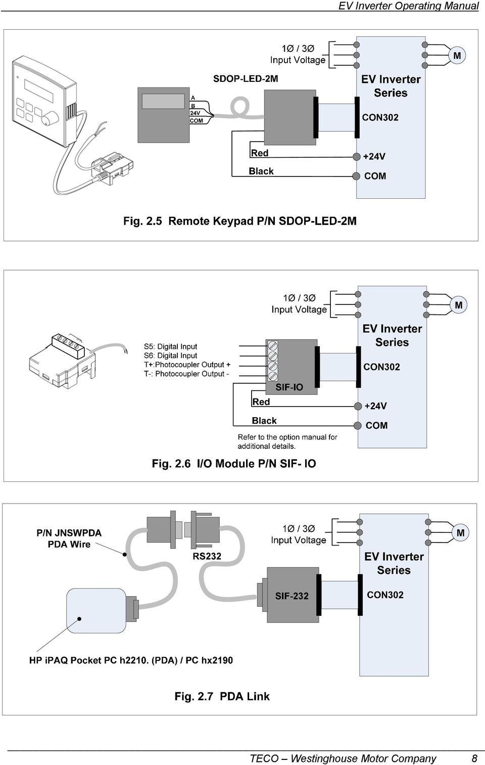
7 Section 2 - Option Modules The following Option Modules are available for the EV Inverter series. They are easily installed and are inserted into connector CON 302 by removing the front cover. Caution - When installing option modules, make sure that power has been removed from the inverter and that the charge indicator is extinguished before proceeding. The front cover is removed by using finger pressure to push in on the sides of the cover and lifting up. After the option module has been installed, replace the cover before powering-up the inverter. Do not operate the inverter with the cover removed. Option Part Number Description FIG. No. SIF RS485 Interface 2.2 SIF RS232 Interface 2.3 SIF - MP Copy Module 2.4 SDOP LED 2M Remote Keypad 2.5 SIF IO I/O Expansion 2.6 PDA Link SIF RS232 Interface JNSWPDA PDA Cable Interface 2.7 Option Cards Plug into Connector Con 302 (SIF-IO Module shown) Fig. 2.1 Option Card Installation and Wiring TECO Westinghouse Motor Company 6

8 TECO Westinghouse Motor Company 7

9 TECO Westinghouse Motor Company 8
10 Section 3 - Control Signal Terminal Block Description Terminal No. Terminal Designation Description 1 RA Multi function digital output NO contact rated 10A 2 RB Refer to parameter F21 ( ) for selecting output functions 3 24V 4 S1 5 S2 6 S3 7 S4 8 COM 9 10V 10 AIN / S7 11 COM 12 FM+ 20mA Max. - Provides the common point for the multi function digital inputs S1 S4 when SW1 is set to PNP (Source Mode). - Provides input power for the various option cards when required. Multi function digital input terminals Refer to parameters F11 F14 ( ,019) for selecting input functions Output common - Provides a common for both the 10V (terminal 9) and 24V (terminal 3) sources - Provides the common point for the multi function digital inputs S1 S4 when SW1 is set to NPN (Sink Mode). - Provides a common for various option cards 20mA Max. - Reference voltage supply for an external speed control potentiometer. Analog or digital - AIN Analog: When terminal 10 is used as an analog input refer to parameters F15 (017 & 018), F16 ( ), F17, F18, F19 ( ) and F20 ( ). - S7 Digital: When terminal 10 is used as a digital input, parameters described for multi function digital input terminals S1 S4 apply. NOTE : Logic level high; => +8V* logic level low level; =< 2V *Caution! Do not exceed 10V maximum. Output common - Same as terminal 8 Multi function analog output 0 +10VDC, Refer to parameter F26 ( ) for output functions. TECO Westinghouse Motor Company 9

11 Section 4 - Input Power Terminal Block Description L1(L) L2 L3(N) PE Fig. 4.1 Power Input Terminal Designations Terminal Designation L1(L) L2 L3(N) Main power input : (Single Phase) ( L) (N) (Three Phase) L1 L2 L3 Description *( VAC or VAC) *( VAC or VAC) * PE Earth Ground Caution - *Refer to the inverter nameplate for input voltage specifications Section 5 - Output Power (Motor and Brake) Terminal Block Description * Terminal Designation P N T1 T2 T3 PE DC Power and braking unit Description Inverter power output (Motor connections) *3Ø (Three Phase) 0 200Hz Max. Earth ground Caution - *Refer to the inverter nameplate for output voltage specifications TECO Westinghouse Motor Company 10
 * PE Earth Ground Caution - *Refer to the inverter nameplate for input voltage specifications Section 5 - Output Power (Motor and Brake) Terminal Block")
12 Section 6 - Peripheral Power Devices The following describes some of the precautions that should be followed when selecting peripheral power devices. Power Supply Induction Motor Molded Circuit Breaker or Fuse Magnetic Contactor AC Reactor Input Noise Filter EV Inverter Output Noise Filter Power supply: Make sure the correct voltage is applied to avoid damaging the inverter. Molded-case circuit breaker (MCCB) or fused disconnect A molded-case circuit breaker or fused disconnect must be installed between the AC source and the inverter that conforms to the rated voltage and current of the inverter to control the power and protect the inverter. (See section 7 for fuse ratings) Do not use the circuit breaker as the run/stop switch for the inverter. A suitable fuse should be installed with inverter rated voltage and current when a MCCB is not being used. (Please refer to Sec.7 for recommended current ratings) Ground fault detector / breaker: Install a ground fault breaker to prevent problems caused by current leakage and to protect personnel. Select current range up to 200mA, and action time up to 0.1 second to prevent high frequency failure. Magnetic contactor: Normal operations do not need a magnetic contactor. When performing functions such as external control and auto restart after power failure, or when using a brake controller, install a magnetic contactor. Do not use the magnetic contactor as the run/stop switch for the inverter. AC line reactor for power quality: When inverters are supplied by a high capacity (above 600KVA) power source, an AC reactor can be connected to improve the power factor. Input and output noise filter: A filter must be installed when there are inductive loads affecting the inverter. Inverter: Output terminals T1, T2, and T3 are connected to U, V, and W terminals of the motor. If the motor runs in reverse while the inverter is set to run forward, swap any two terminals connections for T1, T2, and T3. To avoid damaging the inverter, do not connect the input terminals T1, T2, and T3 to AC input power. Connect the ground terminal properly.( 230V series: Rg <100Ω; 460V series: Rg <10Ω.) TECO Westinghouse Motor Company 11
 or fused disconnect A molded-case circuit breaker or fused disconnect must be installed between the AC source and the inverter that conforms to the rated voltage")
13 Section 7 - Fuse Types and Ratings Inverter input fuses are provided for safely disconnecting the inverter from the input power in the event of a failure in the inverter s power circuitry. The inverter s electronic protection circuitry is designed to clear inverter output short circuits and ground faults without blowing the inverter input fuses. The table below shows the EV input fuse ratings; To protect the inverter most effectively, use fuses with current-limiting capabilities. RK5 and CC/T type fuse ratings for the EV AC Drive series JNEV- HP KW KVA 115V class (1Ø) 100% CONT Output AMPS Max.RK5 FUSE Rating(A) Max.CC or T FUSE Rating(A) 1P2-H P5-H H JNEV- HP KW KVA 230V class (1Ø) 100% CONT Output AMPS Max.RK5 FUSE Rating(A) Max.CC or T FUSE Rating(A) 2P2-H P5-H H H H V class (3Ø) 100% CONT Max.RK5 Max.CC or T JNEV- HP KW KVA Output AMPS (A) FUSE Rating(A) FUSE Rating(A) 2P2-H P5-H H H H V class (3Ø) 100% CONT Max.RK5 Max.CC or T JNEV- HP KW KVA Output AMPS (A) FUSE Rating(A) FUSE Rating(A) 401-H H H Note: Fuse ratings are based upon 300V fuses for 120V inverters, 300V fuses for 230V inverters, and 500V for 460V inverters. TECO Westinghouse Motor Company 12
 100% CONT Output AMPS Max.RK5 FUSE Rating(A) Max.CC or T FUSE Rating(A) 1P2-H1 0.25 0.2 0.53 1.")
14 Section 8 - Quick Start Guide This guide is a step by step procedure to assist in installing and operating the inverter with a motor to verify that they work properly. Starting, stopping, and motor speed will be initially controlled from the keypad. After the initial check has been completed, the inverter may then be configured for a particular application that may require external control or special systems programming. Step 1: Before starting the inverter Safety First! Please refer to Section 1 Safety precautions, before proceeding. Check inverter and motor nameplate to determine that they have the same HP and voltage ratings. (Ensure that full load amps of the motor does not exceed that of the inverter.) With power OFF, wire and verify that AC power is connected to L1(L), L2, and L3(N). CAUTION - For single phase power, apply only to terminals L1(L) and L3(N) Wire and verify that the motor leads are connected to T1, T2, and T3. When using a braking module, connect the terminal voltage of the braking unit to (P+ and N ) terminals on the inverter. Power Indicator Step 2: Apply power to the inverter Apply the appropriate AC power to the inverter and observe the keypad display. The 3 digit 7- segment display should show the input power voltage for 3-5 seconds and then show the frequency command value of 05.0 (factory default). At this point the display will be blinking. The Power ON Indicator LED should also be ON. Step 3: Check motor rotations without load On the keypad, press the RUN key. The display will be on steady and indicate 00.0 to 05.0, which is the value of the inverter output frequency applied to the motor. Verify the operation and direction of the motor. If the direction of the motor is incorrect, press the STOP Key, and turn OFF the AC power. Before proceeding any further verify that the Power Indicator LED on the inverter keypad is COMPLETELY OFF. Swap the leads connected to the inverter T1 and T2 terminals. Go to Steps 2 and 3 and recheck the motor direction. Press the STOP key. Step 4: Check motor full speeds at 50Hz/60Hz On the keypad, change the inverter output frequency with the, arrows, and then press the DATA/ENT key to store the new value. In this case set it to 60Hz. Press the RUN /STOP key, and observe the motor operation as it accelerates to full speed. Press the RUN/STOP key, and observe the motor operation as it decelerates to 0 speed. After satisfying the above, you can proceed with setting the application specific parameters and permanent installation. TECO Westinghouse Motor Company 13

15 Section 9 - Keypad Key Functions and Navigation The EV keypad, Fig. 9.1, provides all the necessary functions to allow full control of the EV inverter. The keypad has membrane type keys and a 7-segment 3-digit LED display. Also located on the keypad is a potentiometer that can be used to control inverter output frequency when selected as the control source. There is also an LED indicator which serves to show both power on as well as a DC bus charge indicator when power is removed. A remote keypad is available as an option, and is covered more in detail in the Option Modules (See section 2). Fig. 9.1 EV Keypad 9.1 Key Functions The keys are multifunctional, providing for both control of the inverter when keypad mode is selected (Default) and access in setting various parameters. The key functions are as follows. TECO Westinghouse Motor Company 14

16 9.2 Keypad Navigation When attempting to control and set various parameters for the inverter it would be useful for the user to become familiar with keypad navigation and to go through a few function changes before making the final settings Basic Keypad Control (Factory Default, F04=000 & F05=000) Fig In its basic form as received from the factory, the inverter output is controlled from the keypad. Please refer to the F and C parameter list (Sec. 10) to view the factory default settings for the various parameters. When the inverter is powered up, the display will be flashing and momentarily show the inverter input voltage. The display will then switch to a minimum output frequency of 05.0Hz. By pressing the RUN / STOP key the output is active (RUN) and the display is on solid. Using the UP / DOWN keys, the output frequency may be set in increments of 00.1Hz from 00.0 to 50.0/60.0Hz. This can be done when the inverter is in the RUN or STOP mode. When the RUN / STOP key is toggled to STOP, the set frequency is displayed and the display is again flashing. The Down key also functions to initiate a RESET after a Fault is cleared. 9.3 Local / Remote Function In Local mode: The RUN command is controlled by the RUN / STOP RUN STOP key. Frequency command -If C41= 000: The UP / DOWN keys control the output RESET frequency. -If C41= 001: The front panel potentiometer controls the output frequency. In Remote mode: The RUN command is controlled via the function set by (F04) The frequency command is set by the function set by (F05) To toggle between Local / Remote press the DATA ENT RESET keys simultaneously. TECO Westinghouse Motor Company 15

17 9.4 Setting Parameters F(Basic) and C(Advanced) Fig The basic parameters F can be accessed in two ways; via the keypad or through the MODBUS protocol using an optional communications module. Here we will describe keypad access. Before proceeding, refer to the F and C parameter lists (Sec. 10) and note that some parameters must be changed with the inverter in the STOP mode while others can be changed in either the RUN or STOP mode. Also, changing certain parameters may affect other functions and should be carefully considered before making those changes. To enter the F parameters, press the DSP / FUN key; the display should show F00. Using the Λ / V keys, select the parameter to set and then press the DATA / ENT key. The display should be showing the existing code or function for that parameter. Using the Λ / V keys, select the desired code or function and then press the DATA / ENT key to save; the display should momentarily flash End and return to the F menu. To enter the C (advanced) parameters select F51 and then Code = 001; C00 will be displayed. Using the same procedure in setting the F parameters scroll to the desired C parameter and select the code or function to be set and then press the DATA / ENT key to save. To return to the F parameter list press the DSP / FUN key twice and set F51 to Code = 000. After all parameter changes have been made, press the DSP / FUN key to return the display show the output frequency. Toggles display between the set output frequency and F parameters Returns to F menu parameters displayed Scroll from F00 to F54 Scroll to function or code Parameter function or value Set F51=000 To return to F parameters Returns to Advanced menu parameters displayed Scroll from C00 to C55 Scroll to function or code Parameter function or value TECO Westinghouse Motor Company 16

18 Section 10 - Parameters F (Basic) and C (Advanced) Function Tables Overview The EV Inverter Series is program capable to allow for a variety of application requirements. The parameters are split into two categories, F and C. The F parameters set the Basic functions of the inverter while the C parameters control the more Advanced functions. The parameters can be accessed and changed through the keypad. (Refer to Sec.9 for keypad functions and navigation). They may also be accessed and changed though MODBUS protocol in conjunction with an optional communications module (Refer to Sec. 2 for available communication options). When the inverter is shipped from the factory each parameter is set at a Factory Default value and is so specified in the Tables. Most parameters may not be changed when the inverter is in the RUN mode. Those parameters that can be are so noted (note 1) in the Remarks column. Table 10.1 F (Basic) Parameters F Parameter Code Range/ Function F00 Inverter horsepower capacity code Factory Default Remarks - Note 5 F01 Acceleration time 1 (sec.) Note 1 & 2 F02 Deceleration time 1 (sec.) Note 1 & 2 F03 F04 Motor rotation direction Run command source 000 Forward 001 Reverse 000 Keypad 001 External terminal 002 Communication control 000 UP/Down key on keypad 000 Note F05 Frequency command source 001 Potentiometer on keypad 002 AIN (input signal from TM2) Multi-function input terminal UP/DOWN function 004 RS-485 Communication frequency setting Forward / Stop Reverse / Stop External control operation F06 Run / Stop- 000 mode 001 Forward / Reverse wire Run / Stop F07 Frequency upper limit (Hz) / 60.0 Note 2 & 7 F08 Frequency lower limit (Hz) Note 2 TECO Westinghouse Motor Company 17
.")
19 F09 F10 F11 F12 F13 F14 F15 Stopping method Status display parameters Terminal S1 function Terminal S2 function Terminal S3 function Terminal S4 function AIN Can be set as an analog input (017 Factory default or 018) or as a digital input and becomes S7 000 Decelerate to stop 001 Coast to stop 000 Disable 001 Enable 000 Forward 001 Reverse 002 Preset speed command Preset speed command Preset speed command Jog frequency command 006 Emergency stop (E.S.) 007 Base block (b.b.) 008 Select 2 nd acceleration / deceleration time 009 Reset 010 Up command 011 Down command Note 1 S1 = 000 S2 = 001 S3 = 005 S4 = 006 AIN = 017 Note: Digital inputs S1 S4, *S5 and S6 and S7 can be programmed with Codes and 019 only. Codes 017 and 018 are reserved for when AIN is used as an analog input 012 Control signal switch 013 Communication control signal switch *Digital Inputs S5 & S6 are provided by an optional I/O Module SIF-IO. ( see Sec., Fig. 2.6) *F16 AIN signal select 014 Acceleration / deceleration prohibit 015 Master / Auxiliary speed source select 016 PID function disable 017 Analog signal input (terminal AIN) 018 PID feedback signal (terminal AIN) 019 DC Injection brake signal V (0-20mA) V( 4-20mA) *F17 AIN gain (%) *F18 AIN bias (%) *F19 AIN bias *F20 AIN slope direction 000 Positive 001 Negative 000 Positive 001 Negative Note 1 * Parameters F16 F20 are used when F15 is selected as an analog input 017 or 018 TECO Westinghouse Motor Company 18

20 F21 F22 F23 Multi-function output RY1 Preset output frequency target (Hz) Target frequency detection range (±Hz) 000 Run 001 Frequency reached (Set frequency ± F23) 002 Frequency is within the range set by (F22±F23) 003 Frequency detection (>F22) 004 Frequency detection (<F22) 005 Fault terminal 006 Auto reset and restart 007 Momentary power loss 008 Emergency stop (E.S.) 009 Base block (b.b.) 010 Motor overload protection 011 Inverter overload protection 012 Not used 013 Power on 014 Communication error 015 Output current detection(>f24) Note Note 1 F24 Output current target value (%) F25 F26 F27 F28 F29 Output current detection time(sec.) Multi-function analog output type selection (0-10VDC) Multi-function analog output gain (%) Preset frequency 1 (Main frequency setting) (Hz) Preset frequency 2 (Hz) Output frequency 001 Set frequency 002 Output voltage 003 DC voltage 004 Output current 005 PID feedback signal 000 Note Note Note 1& Note 1&2 F30 Preset frequency 3 (Hz) Note 1&2 F31 Preset frequency 4 (Hz) Note 1&2 F32 Preset frequency 5 (Hz) Note 1&2 F33 Preset frequency 6 (Hz) Note 1&2 F34 Preset frequency 7 (Hz) Note 1&2 F35 Preset frequency 8 (Hz) Note 1&2 F36 Jog frequency setting (Hz) Note 1&2 TECO Westinghouse Motor Company 19
 Multi-function analog output type selection (0-10VDC) Multi-function analog output gain (%) Preset frequency 1 (Main frequency setting) (Hz) Preset frequency 2 (Hz) - 00.0 25.5 00.")
21 F37 DC braking time (sec.) F38 DC braking start frequency (Hz) F39 DC braking level (voltage %) F40 Carrier frequency (khz) F41 Auto restart after power-loss 000 Enable 001 Disable F42 Auto-restart attempts Note 6 F43 Motor rated current - Note 4 F44 Motor rated voltage - Note 4 F45 Motor rated frequency - Note 4 F46 Motor rated power - Note 4 F47 Motor rated speed (*100RPM) *7 Note 4 F48 F49 F50 F51 F52 Torque boost gain (Vector mode) Slip compensation gain (Vector mode) Low frequency voltage compensation Advanced (C)parameter function display Factory default Disable 001 Enable Reset to factory default (50Hz) Reset to factory default (60Hz) F53 Software version - CPU version F54 Latest 3 fault records - F Parameter Notes: 1 - Can be changed during RUN mode. 2 - Frequency resolution is 1Hz for settings above 100Hz. 3 - Cannot be modified via RS485 communication. 4 - Remains unchanged after reset to factory default. F52 factory setting is 020(60HZ) and motor parameter value is 7.0. F52 factory setting is 010(50HZ) and motor parameter value is Please consult factory before making any parameter adjustments 6 - Changed in Software version 1.5 or later 000 Note 1 7 Default setting for North American units is to the right of the /; setting for all other units are to the left. 000 Notes 3 & 4 Notes 3 & 4 TECO Westinghouse Motor Company 20
22 Table 10.2 C (Advanced) Parameters (Set F51=001 to access) C Function Description Code Range / Function 000 Reverse enable C00 Reverse run 001 Reverse disable Factory default 000 Remarks C01 C02 C03 C04 C05 Acceleration stall-prevention Acceleration stall-prevention level (%) Deceleration stall-prevention Deceleration stall-prevention level (%) Run stall-prevention Acceleration stall prevention enable Acceleration stall prevention disable Deceleration stall prevention enable Deceleration stall prevention disable Run stall prevention enable Run stall prevention disable 000 C06 Run stall-prevention level (%) C07 C08 C09 Stall prevention foldback time during run Stall prevention deceleration time set (sec.) Direct start on power up Follow the deceleration time set in F02 Follow the deceleration time set in C Note Direct start enabled 001 Direct start disabled 001 C10 Reset mode 000 RUN instruction must be OFF before the reset command is available Whether RUN 001 instruction is OFF or ON, the reset command is always available C11 Acceleration time 2 (sec.) Notes 1&2 C12 Deceleration time 2 (sec.) Notes 1&2 000 TECO Westinghouse Motor Company 21
23 C13 Fan control Auto-run at or above set temperature Run whenever the inverter runs 002 Always running 003 Always stopped 001 This function only available for enclosure type IP20, For enclosure type IP65, fan will run while power is on. C14 Control mode 000 Vector control 001 V/f control 000 Note 4 C15 V/f Pattern setting /004 Note 6 &7 C16 V/f Base output voltage setting (VAC) - 198~265V / 380~530V 220/440 Note 7 C17 Max output frequency (Hz) /60.0 Note 7 C18 Output voltage ratio at max frequency (%) C19 Mid frequency(hz) /30.0 Note 7 C20 Output voltage ratio at mid frequency (%) C21 Min output frequency (Hz) /00.6 Note 7 C22 C23 C24 Output voltage ratio at Min frequency (%) Torque boost gain (V/f) (%) Slip compensation gain (V/f) (%) C25 Motor no load current (A) - C26 Electronic thermal relay protection for motor (OL1) Note Note Enable motor protection 001 Disable motor protection Varies with motor rating Note Note 8 C27 Skip frequency 1(Hz) Note 1&2 C28 Skip frequency 2(Hz) Note 1&2 C29 Skip frequency range (±Hz) Note 1 TECO Westinghouse Motor Company 22
24 000 PID Function disabled 001 PID Control, bias D control C30 PID operation mode 002 PID Control, feedback D control PID Control, bias D reverse characteristics control. PID Control, feedback D 004 reverse characteristics control. C31 PID Error gain Note 1 C32 P: Proportional gain Note 1 C33 I: Integral time (sec.) Note 1 C34 D: Differential time (sec.) Note 1 C35 PID Offset 000 Positive direction 001 Negative direction 000 Note 1 C36 PID Offset adjust (%) Note 1 C37 PID Update time (sec.) Note 1 C38 PID Sleep mode threshold (Hz) C39 PID Sleep delay time (sec.) UP/Down command is available. Set frequency is held when inverter stops. C40 Frequency Up/Down control using MFIT 001 UP/Down command is available. Set frequency resets to 0Hz when inverter stops UP/Down command is available. Set frequency is held when inverter stops. Up/Down is available when stopped. TECO Westinghouse Motor Company 23
25 C41 Local/Remote frequency control select (Run command by the Run/Stop key) UP/Down key on keypad sets frequency Potentiometer on the keypad set frequency Forward 001 Reverse 002 Preset speed command Preset speed command Preset speed command Jog frequency command 006 Emergency stop (E.S.) C42 C43 Terminal S5 function Terminal S6 function 007 Base block (b.b.) 008 Select 2 nd acceleration / deceleration time 009 Reset 010 Up command 011 Down command C44 C45 Note: Terminals S5 and S6 are provided by an SIF-IO option card. Multi-function input terminals S1-S6 signal scan time (msec 8) AIN signal scan time (msec x 8 ) 012 Control signal switch 013 Communication control signal switch 014 Acceleration / deceleration prohibit 015 Master / Auxiliary speed source select 016 PID Function disable 017 Analog signal input (terminal AIN) 018 PID Feedback signal (terminal AIN) 019 DC Injection brake signal Not used with S5 and S6 TECO Westinghouse Motor Company 24
26 000 Run 001 Frequency reached (Set frequency ± F23) 002 Frequency is within the range set by (F22±F23) C46 Multi-function output T+, T- (Photocoupler) Note: This function is provided by an SIF-IO option card 003 Frequency detection (>F22) 004 Frequency detection (<F22) 005 Fault terminal 006 Auto reset and restart 007 Momentary power loss 008 Emergency stop(e.s.) 009 Base block (b.b.) 010 Motor overload protection 011 Inverter overload protection 012 Not used 013 Power on 014 Communication error 015 Output current detection (>F24) Disable (no signal loss detection) Note 4 C47 Remote keypad control selection Note: The remote keypad is an option Enable. On signal loss stop according to F09 Enable. Runs at the last set frequency. On signal loss stop according to F04 setting or Stop key on keypad. 000 Stop inverter then connect remote keypad for proper operation C48 C49 C50 C51 C52 Copy module Note: This function is provided by the Copy Module option card Inverter communication address Note: SIF-232 or SIF-485 required Baud rate (bps) Note: SIF-232 or SIF-485 required Stop bit Note: SIF-232 or SIF-485 required Parity bit Note: SIF-232 or SIF-485 required 000 Copy module disable Copy to module from inverter Copy to inverter from module 003 Read / Write check 000 Note Notes 3& Stop bit Stop bits 000 No parity 001 Even parity 002 Odd parity 003 Notes 3&4 000 Notes 3&4 000 Notes 3&4 TECO Westinghouse Motor Company 25
27 C53 C54 Data bits Note: SIF-232 or SIF-485 required Communication error detection time (sec.) Note: SIF-232 or SIF-485 required Bits data Bits data (Only for MODBUS ASCII Mode) 000 Notes 3& Notes 3&5 Deceleration to stop. (Deceleration time = F02). C55 Communication error operation selection Note: SIF-232 or SIF-485 required 001 Coast to stop. 002 Deceleration to stop. Deceleration time = C12) 000 Notes 3&5 003 Continue operating. C Parameter Notes: 1 - Can be changed during RUN mode. 2 - Frequency resolution is 1Hz for settings above 100Hz. 3 - Cannot be modified via RS-485 communication. 4 - Does not change after reset to factory default. F52 factory setting is 020(60HZ) and motor parameter value is 7.0. F52 factory setting is 010(50HZ) and motor parameter value is Available in Software version 1.2 or later. 6 - Changed in Software version 1.7 or later 7 - Default setting for North American units is to the right of the /; setting for all other units are to the left. 8 - Please consult factory before making any parameter adjustments TECO Westinghouse Motor Company 26
28 Section 11 - Parameters F (Basic) and C (Advanced) Function Descriptions F (Basic) Parameter Function Descriptions F00 Inverter horsepower capacity F00 Inverter model F00 Inverter model 1P2 1P P5 1P JNEV P2 JNEV 2P P5 2P F01 Acceleration time 1 (sec) : F02 Deceleration time 1 (sec) : Formula for acceleration/deceleration time: Denominator is based on the setting of C14 a) Motor rated frequency (Sensorless vector control C14=000) b) Max output frequency (V/f mode C14=001) a) Vector Set frequency Set frequency Accel time = F01 Decel time = F02 F45 (rated frequency) F45 (rated frequency) b) V/F Set frequency Set frequency Accel time = F01 Decel time = F02 C17 (Max. output freq.) C17 (Max. output freq.) 000: Forward F03 Motor rotation direction 001: Reverse Parameter F04 must be set to 000 for this function to be effective. 000: Keypad F04 Run signal source 001: External terminal 002: Communication control 1. ) F04=000: inverter is controlled by the keypad. 2. ) F04=001: inverter is controlled by external signals via the I/O terminal, TM2. 3. ) F04=002: inverter is controlled by serial communications. F05 Frequency signal source 000: UP/Down key on keypad 001: Potentiometer on keypad 002:TM2 input signal (Terminal AIN) 003: Multi-function input terminal UP/DOWN function 004: Frequency set by communication method ( NOTE: When C47=1, the remote keypad has priority) TECO Westinghouse Motor Company 27
29 1.) F5=001: When any parameter F11- F15 is set to 015 and the multi-function input terminal is OFF, the frequency is set by the potentiometer on the keypad. If the multi-function input terminal is ON, the frequency is set by the analog signal (AIN) from TM2. 2.) F5=002: When any parameter F11 - F15 is set to 015 and the multi-function input terminal is OFF, the frequency is set by the analog signal (AIN) from TM2. If the multi-function input terminal ON, the frequency is set by the potentiometer on the keypad. 3.) F5=003: Up / Down terminal: Refer to the description of parameters F11- F15 (multi-function input terminal). 4.) Priority of frequency command; Jog> preset frequency > (keypad or TM2 Up / down or communication) F06 External control operation mode 000: Forward / Stop Reverse / Stop 001: Run / Stop - Forward / Reverse 002: 3-wire Run / Stop 1.) F06 is only available when F04 = 001 (TM2 terminal). 2.) When both forward and reverse commands are ON, this will result in a stopped mode. NOTE: In 3 wire control mode, terminals S1-S3 are dedicated, therefore parameters F11 - F13 are ineffective. TECO Westinghouse Motor Company 28
30 Fig. 11.1d Control Method Sequences NOTE: If C00=001, the reverse command is disabled. F07 Frequency upper limit (Hz) : F08 Frequency lower limit (Hz) : Output frequency (See note below) Fig Frequency Limits F07 (Frequency upper limit) F08 (Frequency lower limit) Commanded frequency NOTE: If F07 = 0Hz and frequency command = 0Hz, the inverter will zero-speed stop. If F08 > 0Hz and frequency command <F08, the inverter will run at the F08 set value. 000: Decelerate to stop F09 Stopping method 001: Free run ( Coast) to stop 1.) F09 = 000: after receiving a stop command, the motor will decelerate to stop at the rate set in F02, deceleration time 1. 2.) F09 = 001: after receiving a stop command, the motor will free-run (Coast) to stop. TECO Westinghouse Motor Company 29
31 F10 Status monitoring 000: Disable display 001: Enable F10 = 001: Display motor current, voltage, DC bus voltage, and PID feedback along with frequency. F10 = 000: Display frequency only. F11-15 Selectable Functions for input terminals ( S1-S4& AIN ) 000: Forward run 001: Reverse run 002: Preset speed command 1 003: Preset speed command 2 004: Preset speed command 3 005: Jog frequency command 006: External emergency stop (E.S.) 007: Base block (b.b.) 008: Switch to 2nd acceleration / deceleration time 009: Reset 010: Up command 011: Down command 012: Control signal switch 013: Communication mode. Disable / Enable. 014: Acceleration / deceleration prohibit 015: Master / Auxiliary speed switch 016: PID function disable 017: Analog frequency signal input ( terminal AIN) 018: PID feedback signal (terminal AIN) 019: DC Brake signal 1.) S1 - AIN on TM2 are the multi-function input terminals which can be set to the above 19 functions. 2.) F11 - F15 function descriptions: F11 - F15=000 / 001: Forward/ Reverse When the Forward command is ON, the inverter runs forward; when OFF the inverter stops. F11 is the factory default Forward command. When the Reverse command is ON, the inverter runs in reverse; when OFF the inverter stops. F12 is the factory default Reverse command. NOTE: If both forward and reverse command are ON at the same time the inverter will activate Stop mode. F11 - F15= : Preset speed commands 1-3 When the run signal is applied and any of the selected external multi-function input terminals are ON, the inverter will run at one of 8 preset speeds depending on the combined state of all the multi-function input terminals. The corresponding speeds are programmed by parameters F28 to F36 as shown in the table on the next page. F11 - F15=005: Jog frequency command When a run signal is applied and the selected external multi-function input terminal is configured for Jog speed and is active (On), the inverter will run at the frequency programmed in the F36 setting. (See table on next page) NOTE: Priority of the frequencies: Jog > Preset Speed TECO Westinghouse Motor Company 30
32 Preset Speed Command 3 Set value=004 Preset Speed Command 2 Set value=003 Preset Speed Command 1 Set value=002 Jog Frequency Command Set value=005 Output frequency set value X X X 1 F F F F F F F F F35 X = 1 or 0 F11 - F15=006: External Emergency Stop (E.S.) Upon receiving an external Emergency Stop signal the inverter will decelerate to a stop by the value set by C12, the 2 nd deceleration time setting regardless of the F09 deceleration setting and the display will flash E.S. The inverter will restart only when the Emergency Stop signal is removed and the start signal is removed and re-asserted (remote mode), or the Run key is pushed (keypad mode). Removing the Emergency Stop signal before the inverter has fully stopped will not cancel the Emergency Stop operation. The output relay can be set to Emergency Stop fault by setting F21=008. F11 - F15=007: Base Block (b.b.) The inverter will stop immediately (coast to stop) upon receiving the Base Block signal regardless of the setting of F09 and the display will flash b.b. The inverter will auto restart in a speed search mode when the Base Block signal is removed. F11 - F15=008: Switching to 2nd acceleration / deceleration time When the external terminal is ON the 2nd acceleration / deceleration time are in effect. (Refer to parameters C11, C12 for the time settings) F11=009: Reset command When the reset command is ON, the inverter will be disabled and all re-settable table faults will be cleared. NOTE: Do not use a maintained device on the Reset input. F11 - F15=010 / 011: Up / Down functions (Controlled by acceleration / deceleration times) Set F05=003 to enable the Up / Down function. Set C40=000, When the Up / Down terminal is ON, the inverter begins accelerating / decelerating to the set frequency and stops when the UP / DOWN signal is removed. The inverter continues to run at that frequency. Setting C40=002 will operate identically as C40 = 000 except that the reference frequency can now be modified with the Up / Down terminals when the inverter is stopped. The inverter will decelerate to stop or coast to stop when the Run command is OFF depending on the deceleration setting of F09. The frequency at which the inverter will re-start is stored in F28. NOTE: The Up / Down keys on the keypad are disabled for changing the frequency when F05=003, but the frequency can be modified by setting Parameter F28. Set C40=001, The inverter will accelerate from 0Hz (stop) upon receiving a run command. The Up / Down action is similar to the description above. When the run command is removed, the inverter will decelerate to a stop or coast to a stop depending on the deceleration setting of F09. The inverter will accelerate from 0Hz each time a run command is given. NOTE: The Up / Down commands are disabled if both Up and Down terminals are ON at the same time. TECO Westinghouse Motor Company 31
33 F11 - F15=012: Control signal switch External control terminal OFF: The operation and frequency signals are controlled by parameter settings in F04 / F05. External control terminal ON: The operation and frequency signals are controlled by the keypad. F11 - F15=013: Communication mode select. External control terminal OFF: The inverter is controlled by the master (Host Computer or PLC) for run / frequency signals and allows parameter modifications. The Keypad and TM2 run / frequency signals are disabled. The keypad is only available to display voltage / current / frequency and read parameters but cannot modify them. It is also available for emergency stop. External control terminal ON: The Host Computer or PLC can read and modify parameters, but the inverter can only be controlled from the keypad. (Not affected by settings of F04 & F05). F11 - F15=014: Acceleration / deceleration prohibit When the external control terminal is ON, the inverter will stop acceleration/ deceleration until the signal is removed. The operation is as follows: Fig Acceleration / Deceleration Prohibit F11 - F15=015: Master / Auxiliary speed switch 1) F05=001, when one of the parameters F11 - F15 is set to 015, and the multi-function input terminal is OFF and the frequency is set by the potentiometer on the Keypad (Master speed). When the multi-function input terminal is ON, the frequency is set by the analog signal at terminal AIN. 2.) F05=002, when one of the parameters F11 - F15 is set to 015, and multi-function input terminal is OFF, the frequency is set by the analog AIN. When the multi-function input terminal is ON, the frequency is set by the potentiometer on the Keypad (Auxiliary speed). F11 - F15=016: PID function disable When the input terminal is ON, PID operation and functions set by C30 - C39 are disabled. When the input terminal is OFF, PID operation and functions set by C30 - C39 are enabled. F15=017: Analog frequency signal input (Terminal AIN) A 0-10VDC or 4-20mA signal can be used as a frequency reference at terminal AIN as set by F16 and switch SW2 (select between 0-10Vdc or 0/4-20mA). F15=018: PID Feedback signal input (Terminal AIN) The PID feedback signal can be connected to the analog input terminal AIN 0-10VDC / 0-20mA or 2-10VDC / 4-20mA as set by F16 and switch, SW2 (select between 0-10VDC or 0/4-20mA). TECO Westinghouse Motor Company 32
34 F11 - F15=019: DC Injection brake signal The DC injection braking function time and start frequencies are set by parameters F37 and F38. When the TM2 DC injection brake signal is OFF, and the internal brake timer (set by F37) has not expired, the brake timer is reset to the value of F37. When the TM2 DC injection brake signal is ON, and the internal brake time F37 has not expired, DC injection braking is activated. F16 AIN Signal select 000: 0-10V / 0-20mA (Set SW2 to the correct signal : V / I) 001: 2-10V / 4-20mA (Set SW2 to the correct signal : V / I) F17 AIN gain F18 AIN bias (%) (%) F19 AIN bias F20 AIN signal slope direction 000: Positive 001: Negative 000: Positive 001: Negative C45 AIN signal scan time confirmation (msec 8): The AC drive processor reads A/D values every C45 x 8mS. The user can set the scan interval time to suppress any noise levels caused by the operating environment. Extend C45 to increase the filter time if noise is a problem, however the analog signal response will be slower. F19= 000: 0VDC (4mA) corresponds to lower frequency limit, 10VDC (20mA) corresponds to upper frequency limit. F19= 001: 10VDC (20mA) corresponds to lower frequency limit, 0VDC (4mA) corresponds to upper frequency limit. NOTE: Refer to the example tables and figures below for additional information Fig 11.4a setting: Fig 11.4b setting: F17 F18 F19 F20 F17 F18 F19 F20 A 100% 050% C 100% 050% B 100% 000% D 100% 000% Bias 100% 050% 000% 60Hz 30Hz 0Hz 0V (4mA) Hz A 5V B Upper frequency limit (F07=60.0) 10V (20mA) V Bias 100% 050% 0.00% 60Hz 30Hz 0Hz 0V (4mA) Hz D C 5V 10V (20mA) Upper frequency limit (F07=60.0) V Fig 11.4a Fig 11.4c setting: Fig 11.4b Fig 11.4d setting: TECO Westinghouse Motor Company 33
35 F17 F18 F19 F20 F17 F18 F19 F20 E 100% 020% F 100% 050% Hz Hz Bias -000% -020% 60Hz 30Hz 0Hz Upper frequency limit (F07=60.0) E V 2V 10V (7.2mA) (20mA) Bias -000% -050% 60Hz 30Hz 0Hz F 5V (12mA) Upper frequency limit (F07=60.0) 10V (20mA) V -100% -100% Fig 11.4c Fig 11.4d F21 Multi function output RY1 F22 Preset output frequency target F23 Target frequency detection range 000: Run 001: Frequency reached (Preset target frequency ± F23) 002: Frequency reached (Preset output frequency level (F22) ±F23) 003: Frequency detection (>F22) 004: Frequency detection (<F22) 005: Fault output 006: Auto restart 007: Momentary power loss 008: Emergency stop (E.S.) 009: Base block(b.b.) 010: Motor overload protection 011: Inverter overload protection 012: Not used 013: Power on 014: Communication error 015: Output current detection (>F24) Hz Hz TECO Westinghouse Motor Company 34
36 Run Command RUN STOP If Inverter is Stopped the Relay will not Operate Frequency Command Inverter Output Frequency Target frequency detection range F23) Frequency Command Relay Output Signal Target frequency detection range F23) Fig. 11.5a Multifunction Output F21 / C46 = 1 Frequency Reached (Setting Frequency +/- F23) Run RUN Command STOP Preset output Frequency target (F22) Inverter Output Frequency Preset output Frequency target (F22) Relay Output Signal Target frequency detection range (F23) Target frequency detection range (F23) If Inverter is Stopped or has no Reference Frequency the Relay will not Operate Fig. 11.5b Multi-function Output (F21 / C46 = 002) Preset output frequency (F22 ± F23) Reached. TECO Westinghouse Motor Company 35
VCM Installation and Operations Manual. Table of Contents
 Table of Contents VCM Installation and Operations Manual 1.0 Introduction... 1 2.0 Product Inspection... 2 2.1 Nameplate Layout... 2 3.0 Operating Precautions... 3 3.1 Before Power up... 3 3.2 During Power
Emotron VSA Variable Speed Drive
 Emotron VSA Variable Speed Drive Instruction manual English Quick Start Guide This guide is designed to assist in installing and running the variable speed drive to verify that the drive and motor are
GPD 506/P5 Start-up Procedure and Checklist
 GPD 506/P5 Start-up Procedure and Checklist Preparation for GPD506/P5 Drive Start-Up...2 HVAC Start-Up Procedure for GPD 506/P5 WITH Bypass Option:...4 HVAC Start-Up Procedure for GPD 506/P5 WITHOUT Bypass
A1000 Cheat Sheet (Open Loop Vector)
") A1000 Cheat Sheet (Open Loop Vector) The following procedure is a supplement to supplied with this equipment and will guide the user in properly wiring the A1000 and. It will also show the user how to
A1000 Cheat Sheet (Open Loop Vector) The following procedure is a supplement to supplied with this equipment and will guide the user in properly wiring the A1000 and. It will also show the user how to
SAFETY INSTRUCTIONS WARNING
 Important User Information Thank you for purchasing LS Variable Frequency Drives! SAFETY INSTRUCTIONS Always follow safety instructions to prevent accidents and potential hazards from occurring. In this
SAFETY INSTRUCTIONS WARNING
 Thank you for purchasing LG Variable Frequency Drives! SAFETY INSTRUCTIONS Always follow safety instructions to prevent accidents and potential hazards from occurring. In this manual, safety messages are
110V 0.2 0.75KW (0.2 1HP) 220V 0.2 2.2KW (0.2 3HP) 440V 0.75 2.2KW (1 3HP)
 220V 0.2 2.2KW (0.2 3HP) 440V 0.75 2.2KW (1 3HP)") Distributor This manual may be modified when necessary because of improvement of the product, modification, or changes in specifications, This manual is subject to change without notice. Quick Start Guide
Distributor This manual may be modified when necessary because of improvement of the product, modification, or changes in specifications, This manual is subject to change without notice. Quick Start Guide
NX Series Inverters. HVAC Pocket Programming Guide
 NX Series Inverters HVAC Pocket Programming Guide HVAC Pocket Programming Guide HVAC Pocket Programming Guide / Contents This guide provides a single reference document for the user of NXL HVAC (product
FlexPak 3000 Digital DC Drive Software Reference Manual Version 4.3
 FlexPak 3000 Digital DC Drive Software Reference Manual Version 4.3 Instruction Manual D2-3405-2 The information in this manual is subject to change without notice. Throughout this manual, the following
SAFETY INSTRUCTIONS. Always follow safety instructions to prevent accidents and potential hazards from occurring.
 Thank you for purchasing LS Variable Frequency Drives! SAFETY INSTRUCTIONS Always follow safety instructions to prevent accidents and potential hazards from occurring. In this manual, safety messages are
Instruction Manual Copy Adapter "CPAD-C1A" "CP Fuji Electric Systems Co., Ltd. INR-SI47-0886a-EU Rev 052010
 Instruction n Manual Copy Adapter "CPAD-C1A" Thank you for purchasing our Copy Adapter CPAD-C1A. This product is designed to copy function codes and their data, which are stored in the FRENIC-Mini series
Number 1 in efficiency
 PowerXL DE1 Variable Speed Starter www.eaton.eu/de1 Number 1 in efficiency The easiest way of variable motor speed NEW Variation DE11 The new device category! The PowerXL DE1 Variable Speed Starter Why
SAFETY INSTRUCTIONS. Always follow safety instructions to prevent accidents and potential hazards from occurring.
 Thank you for purchasing LS Variable Frequency Drives! SAFETY INSTRUCTIONS Always follow safety instructions to prevent accidents and potential hazards from occurring. In this manual, safety messages are
Remove the terminal cover to expose the motor and power terminals.
 Quick Start Guide This guide is to assist in installing and running the inverter to verify that the drive and motor are working properly. Starting, stopping and speed control will be from the keypad. If
MC Series Drives. Flexible, simple, rugged, robust! Phone: 800.894.0412 - Fax: 888.723.4773 - Web: www.actechdrives.com - Email: info@actechdrives.
 Drives Flexible, simple, rugged, robust! Our promise Commitment to Price Leadership Price leadership is serious business. It takes continuous life cycle management to make price leadership a sustainable
APPENDIX. SureSERVO QUICK START GUIDE. In This Appendix... Quick Start for SureServo Drives...A 2. Tuning Quick Start for SureServo Drives...
 SureSERVO QUICK START GUIDE APPENDIX BA In This Appendix... Quick Start for SureServo Drives.............A 2 Spin the Motor......................................A 2 Position Mode Quick Start (Pt & Pr)......................A
VS-606V7 Series Instruction Manual COMPACT GENERAL-PURPOSE INVERTER (VOLTAGE VECTOR CONTROL)
") VS-606V7 Series Instruction Manual COMPACT GENERAL-PURPOSE INVERTER (VOLTAGE VECTOR CONTROL) PREFACE YASKAWA s VS-606V7 is such a small and simple inverter; as easy as using a contactor. This instruction
VS-606V7 Series Instruction Manual COMPACT GENERAL-PURPOSE INVERTER (VOLTAGE VECTOR CONTROL) PREFACE YASKAWA s VS-606V7 is such a small and simple inverter; as easy as using a contactor. This instruction
ARCO Electric Products Installation and Maintenance Manual Low Voltage Automatic Power Factor Correction Capacitor Systems 2013
 ARCO Electric Products Installation and Maintenance Manual Low Voltage Automatic Power Factor Correction Capacitor Systems 2013 READ CAREFULLY These instructions are intended to cover good practices in
32VFD Variable Frequency Drives for Centrifugal Chillers
 32VFD 32VFD Variable Frequency Drives for Centrifugal Chillers ENERGY-SAVING CONTROL FOR CENTRIFUGAL CHILLERS Reduce energy consumption in your existing centrifugal chiller Your chiller was specified to
VARISPEED V7 IP65 Compact Sensorless Vector Inverter USER S MANUAL
 V7_IP65.qxd 15.02.2006 13:17 Uhr Seite 1 Manual No. I161E-EN-01 VARISPEED V7 IP65 Compact Sensorless Vector Inverter USER S MANUAL OMRON YASKAWA MOTION CONTROL B.V. Wegalaan 65 2132 JD Hoofddorp The Netherlands
Variable Speed AC Motor Drives SM-Basic Installation and Operation Manual
 ELECTRIC MOTORS, GEARMOTORS AND DRIVES Variable Speed AC Motor Drives SM-Basic Installation and Operation Manual We, EC Declaration of Conformity In accordance with EN45014:1998 Leeson Electric Corporation
Operational Overview and Controls Guide
 DOCUMENT: ECSEQ2-1 EFFECTIVE: 02/14/07 SUPERSEDES: 02/26/03 Operational Overview and Controls Guide Standard Two or Three Pump Type VFD Booster Controls 6700 Best Friend Road. Norcross, GA 30071. (770)
VLT 6000 HVAC. Contents
 Contents Introduction Safety...3 Safety Guidelines...3 Warnings Against Unintended Start...3 Introduction...4 About this manual...4 Assumptions...4 References...4 Trademarks...5 Programming the VLT 6000
Softstarters. Type PSTX Fieldbus communication, Built-in Modbus RTU. 1SFC132089M0201 April 2015 1SFC132089M0201 1
 Softstarters Type PSTX Fieldbus communication, Built-in Modbus RTU 1SFC132089M0201 April 2015 1SFC132089M0201 1 1 Modbus RTU The Modbus protocol is a fieldbus protocol that provides full control and status
SINUS M. USER MANUAL -Installation and Programming Instructions-
 15P0073B1 SINUS M VARIABLE FREQUENCY DRIVE USER MANUAL -Installation and Programming Instructions- Issued on 17/02/11 R.03.1 SW Ver. EU2.3 English This manual is integrant and essential to the product.
Application/Connection Examples
 This Quick Start Guide is designed to familiarize the user with the connection and configuration of the DTS-305 DIN rail mounted single / 3 phase power & energy meter with RS-485 or TCP communications.
MEMOBUS/Modbus Communications
 2 2.1 MEMOBUS/MODBUS CONFIGURATION............260 2.2 COMMUNICATION SPECIFICATIONS..............261 2.3 COMMUNICATION TERMINAL RESISTANCE........262 2.4 CONNECTING A PLC...........................263 2.5
Allen-Bradley/Rockwell
 MANUFACTURER DATA SHEET High Speed Counter Manufacturer: Allen-radley/Rockwell Model Number: 1746-HSCE See www.geomartin.com for additional PDF datasheets Martin Part Number: E-014901-03 VendorPartNumber:
1000 Hz High Frequency Custom Software
 YASKAWA AC Drive - V1000 Option 1000 Hz High Custom Software Supplement Software No. VSV91005X To properly use the product, read this manual thoroughly and retain for easy reference, inspection, and maintenance.
SJ200 Series Inverter Quick Reference Guide
 SJ2 Series Inverter Quick Reference Guide Single-phase Input 2V Class Three-phase Input 2V Class Three-phase Input 4V Class Hitachi Industrial Equipment Systems Co., Ltd. Manual No. NB6501XA March 24 Caution:
/ Instruction Manual. Analog Input/Output Interface Card "OPC-G1-AIO"
 / Instruction Manual Analog Input/Output Interface Card "OPC-G1-AIO" Fuji Electric Co., Ltd. INR-SI47-1288b-JE English Version Preface Thank you for purchasing our analog input/output interface card.
Manual No. YEG-TOE-S616-55.1-OY. VARISPEED F7 Vector Control Frequency Inverter USER S MANUAL
 Manual No. YEG-TOE-S616-55.1-OY VARISPEED F7 Control Frequency Inverter USER S MANUAL Table of Content Warnings... VII Safety Precautions and Instructions for Use... VIII EMC Compatibility... X Line Filters...
NC-12 Modbus Application
 NC-12 Modbus Application NC-12 1 Table of Contents 1 Table of Contents... 2 2 Glossary... 3 SCADA...3 3 NC-12 Modbus in general... 3 4 Entire system... 4 4.1 PFC to PC connection alternatives...4 4.1.1
VARIABLE FREQUENCY DRIVES Revised 4/30/2015 23 81 07-1 Mechanical Systems
 SECTION 23 81 07 - VARIABLE FREQUENCY DRIVES PART 1 - GENERAL 1.1 SUMMARY A. This section includes all variable frequency drives. All standard and optional features shall be included within the VFD panel
MC1000 Series Installation and Operation Manual
 MC1000 Series Installation and Operation Manual NOTE! The manual covers software version M108314 and above. Refer to parameter 63 for the software version of the drive you are working with. If you are
Easy to connect - Easy to configure Easy to install
 SIMPLE TO USE... CG Drive- SK is an easy drive - easy to connect, easy to configure and easy to install. Easy to connect - All connectors are generously sized and clearly labeled. Easy to configure - The
SX460. Generator Automatic Voltage Regulator Operation Manual
 SX460 Generator Automatic Voltage Regulator Operation Manual Self Excited Automatic Voltage Regulator Compatible with Newage SX460* * Use for reference purpose only and not a genuine Newage product. 1.
Specifying a Variable Frequency Drive s
 Specifying a Variable Frequency Drive s Put on by Bruce Reeves and Jeremy Gonzales Dykman Electrical Covering the Western US For all of your VFD and Soft Start and Motor Needs How To Specify a Variable
User s Manual Before using the inverter, you need to read and save the safety instructions.
 User s Manual Before using the inverter, you need to read and save the safety instructions. STI SERIES (STI200, STI300, STI500, STI700, STI1000) Power Frequency Pure Sine Wave Inverter The information
Operational Overview and Controls Guide. Two or Three Pump IronHeart Lite with Variable Frequency Drives
 DOCUMENT: ECSEQ6-0 EFFECTIVE: 09/23/10 SUPERSEDES: Operational Overview and Controls Guide Two or Three Pump IronHeart Lite with Variable Frequency Drives 6700 Best Friend Road. Norcross, GA 30071. (770)
Impulse G+/VG+ Series 3, 24 VDC Interface Card Terminal Designations
 Impulse G+/VG+ Series 3, 24 VDC Interface Card Terminal Designations Addendum to: IMPULSE G+ Series 3 Manual (140-10258) IMPULSE VG+ Series 3 Manual (140-10257) This addendum should be used when a 24VDC
1 Application Description... 3. 1.1 Objective... 3 1.2 Goals... 3
 Contents Moxa Technical Support Team support@moxa.com 1 Application Description... 3 1.1 Objective... 3 1.2 Goals... 3 2 System Topology... 3 3 Hardware and Software Requirements... 4 4 Configuration...
Whale 3. User Manual and Installation Guide. DC Servo drive. Contents. 1. Safety, policy and warranty. 1.1. Safety notes. 1.2. Policy. 1.3. Warranty.
 Whale 3 DC Servo drive User Manual and Installation Guide Contents 1. Safety, policy and warranty. 1.1. Safety notes. 1.2. Policy. 1.3. Warranty. 2. Electric specifications. 2.1.Operation ranges. 3. Connections
INSTALLATION & SERVICE MANUAL. Display Panel
 INSTALLATION & SERVICE MANUAL Display Panel The PowerLine EMS TM is a specialized power distribution and energy management system intended to be used in recreational vehicles. The Control Module is housed
MTE SERIES RLW. World REACTORS USER MANUAL PART NO. INSTR 030 REL. 090930. 2009 MTE Corporation
 MTE SERIES RLW World REACTORS USER MANUAL PART NO. INSTR 030 REL. 090930 2009 MTE Corporation IMPORTANT USER INFORMATION NOTICE MTE Series RLW reactors are components designed to improve the reliability
HITACHI INVERTER SJ/L100/300 SERIES PID CONTROL USERS GUIDE
 HITACHI INVERTER SJ/L1/3 SERIES PID CONTROL USERS GUIDE After reading this manual, keep it for future reference Hitachi America, Ltd. HAL1PID CONTENTS 1. OVERVIEW 3 2. PID CONTROL ON SJ1/L1 INVERTERS 3
ACH550 BCR/BDR/VCR/VDR E-Clipse Bypass Drives. User s Manual. ACH550 E-Clipse Bypass User s Manual 2-1
 ACH550 E-Clipse Bypass User s Manual 2-1 ACH550 BCR/BDR/VCR/VDR E-Clipse Bypass Drives 1 400 HP User s Manual ACH550-EB_UM (3AUA0000016461) Rev D EN EFFECTIVE: 2010-04-01 SUPERSEDES: ACH550-EB_UM (3AUA0000016461)
Modular I/O System Analog and Digital Interface Modules
 OPERATING INSTRUCTIONS Modular I/O System Analog and Digital Interface Modules Installation Operation Maintenance Document Information Document ID Title: Operating Instructions Modular I/O System Part
MSN 70. Streç Film & Alüminyum Folyo Sarým Makinesi. Kullanma Kýlavuzu. Mertsan. Makine San. Tic. Ltd.Þti.
 MSN 70 Streç Film & Alüminyum Folyo Sarým Makinesi Kullanma Kýlavuzu Mertsan Makine San. Tic. Ltd.Þti. Tel : + 90 212 550 42 62 Gsm : +90 542 432 17 03 Web : http://www.mertsanmakine.com e-mail : info@mertsanmakine.com
VARIABLE SPEED DRIVE UNIT INVERTER. VAT20 1ph 200V-240V system, 0.2-0.75kW 1ph/3ph 200/240V system, 1.5-2.2kW. 3ph 380/460V system, 0.75-2.
 GE Power Controls VARIABLE SPEED DRIVE UNIT INVERTER VAT20 1ph 200V-240V system, 0.2-0.75kW 1ph/3ph 200/240V system, 1.5-2.2kW 3ph 380/460V system, 0.75-2.2kW INSTRUCTION MANUAL ------------------------------------------------------------
Apéndice E Listado de constantes
 Listado de constantes Operation U1 Monitor U1--01 Frequency Ref Hz -- -- Q Q Q Q U1--02 Output freq Hz -- -- Q Q Q Q U1--03 Output current A -- -- Q Q Q Q U1--04 Control Method -- -- -- Q Q Q Q U1--05
Analog Servo Drive 25A8
 Description Power Range NOTE: This product has been replaced by the AxCent family of servo drives. Please visit our website at www.a-m-c.com or contact us for replacement model information and retrofit
LG Air Conditioning Multi F(DX) Fault Codes Sheet. Multi Split Units
 Fault Codes Sheet. Multi Split Units") Multi Split Units If there is a fault on any LG Multi unit, an Error mark is indicated on the display window of the indoor unit, wired-remote controller, and LED s of outdoor unit control board. A two
Multi Split Units If there is a fault on any LG Multi unit, an Error mark is indicated on the display window of the indoor unit, wired-remote controller, and LED s of outdoor unit control board. A two
AUTOMATIC TRANSFER SWITCH CONTROL UNIT OPERATOR S MANUAL
 ATS-220 AUTOMATIC TRANSFER SWITCH CONTROL UNIT OPERATOR S MANUAL For Use in 208 to 240 Volts Single and 3 Phase ATS Systems With 110Volt AC or DC Control Motors and selenoids 4501 NW 27 ave Miami FL 33142
Phone: 800.894.0412 - Fax: 888.723.4773 - Web: www.clrwtr.com - Email: info@clrwtr.com
 Product description Wide rated operational voltage 208 600 V AC Wide rated control supply voltage 100 250 V, 50/60 Hz Rated operational current 18 to 370 A Wide ambient temperature range, -25 to +60 ºC
Addendum to the Operating Instructions
 Drive Technology \ Drive Automation \ System Integration \ Services Addendum to the Operating Instructions MOVIMOT with AS-Interface and AC Motor DT/DV Unit Replacement MOVIMOT MM..C -> MM..D with MLK3A
Single Phase Soft Starter
 Single Phase Soft Starter Installation & Operating Manual 6/02 Table of Contents Section 1 General Information................................................... 1 1 General Description................................................
User's Guide. Integrating Sound Level Datalogger. Model 407780. Introduction
 User's Guide 99 Washington Street Melrose, MA 02176 Phone 781-665-1400 Toll Free 1-800-517-8431 Visit us at www.testequipmentdepot.com Back to the Extech 407780 Product Page Integrating Sound Level Datalogger
J1000. System configuration
 YASKAWA JZ J1000 The basic inverter V/f controlled inverter Good torque performance (150% / 3 Hz) Double rating ND 120%/1min and HD 150%/1 min Overload detection function (150% during 60s) thermal function
SECTION 26 29 23 VARIABLE FREQUENCY DRIVES
 SECTION 26 29 23 VARIABLE FREQUENCY DRIVES PART 1 GENERAL 1.01 SCOPE A. Furnish and install individual freestanding variable frequency AC drives (VFD) as shown on the Drawings and specified herein. 1.02
Install the DeviceNet Module using the following procedure:
 Installation INSTALLATION INSTRUCTIONS: MCD DEVICENET MODULE Order Code: 175G9002 1. Installation Install the DeviceNet Module using the following procedure: 1. Remove control power and mains supply from
TIG INVERTER INSTRUCTION MANUAL
 TIG INVERTER INSTRUCTION MANUAL Contents Warning General Description Block Diagram Main Parameters Circuit Diagram Installation and Operation Caution Maintenance Spare Parts List Troubleshooting 3 4 4
CAUTION OPC-LM1-IL. Option Card for Encoder of Line Driver Output. Instruction Manual
 Instruction Manual OPC-LM1-IL Option Card for Encoder of Line Driver Output CAUTION Deliver this instruction manual without fail to those who actually operate the equipment. Read this operation manual
2011 Industrial Catalog. DRIVES, PAC, PLCs. Industrial Catalog 2011. www.toshiba.com/ind
 www.toshiba.com/ind 2011 Toshiba International Corporation Rev. 110504 Industrial Catalog 2011 13131 W. Little York Road Houston, TX 77041 Tel: 713-466-0277 Fax: 713-466-8773 US: 800-231-1412 Canada: 800-872-2792
L5354 ControlNet Communications Interface
 L5354 ControlNet Communications Interface Technical Manual HA470733 Issue 2 Copyright SSD Drives Inc 2005 All rights strictly reserved. No part of this document may be stored in a retrieval system, or
MOVFR ELECTRICAL ADJUSTMENTS. G.A.L. MFG. CORP. NEW YORK CITY U.S.A. http://www.gal.com
 MOVFR ELECTRICAL ADJUSTMENTS G.A.L. MFG. CORP. NEW YORK CITY U.S.A. http://www.gal.com 1 ELECTRICAL ADJUSTMENTS ADJUSTING INSTRUCTIONS FOR THE G.A.L. VARIABLE FREQUENCY CLOSED LOOP DOOR OPERATOR TYPE MOVFR
CONSTRUCTION STANDARDS DIVISION 23 HEATING VENTILATING AND AIR CONDITIONING
 PART 1-GENERAL 1.01 DESCRIPTION A. This specification is to cover a complete Variable Frequency motor Drive (VFD) consisting of a pulse width modulated (PWM) inverter designed for use on a standard NEMA
Process modules Digital input PMI for 24 V DC inputs for 120 V AC inputs
 E031026 000823 Process modules Digital input PMI for inputs for 120 V AC inputs PMI Input E4, E5, GND L- PMI 120 V AC Input E4, E5, Common C E6, E7, GND L- E6, E7, Common C LEDs for the inputs operation
CAUTION OPC-LM1-ID. Option Card for Frequency Divider. Fuji Electric FA Components & Systems Co., Ltd. Instruction Manual
 Instruction Manual Option Card for Frequency Divider Deliver this instruction manual without fail to those who actually operate the equipment. Read this operation manual and understand the description
Speed Control Methods of Various Types of Speed Control Motors. Kazuya SHIRAHATA
 Speed Control Methods of Various Types of Speed Control Motors Kazuya SHIRAHATA Oriental Motor Co., Ltd. offers a wide variety of speed control motors. Our speed control motor packages include the motor,
*.ppt 11/2/2009 12:48 PM 1
 Digital Compressor Controller *.ppt 11/2/2009 12:48 PM 1 Copeland Scroll Digital Controller Simple Controller That Enables OEM s To Use Digital Scrolls Relieves OEM From Developing Special Controllers
Technical Manual. FAN COIL CONTROLLER COOLING or HEATING ANALOG or PWM Art. 119914 631001A
 COOLING or HEATING ANALOG or PWM Art. 119914 631001A TOTAL AUTOMATION GENERAL TRADING CO. LLC SUITE NO.506, LE SOLARIUM OFFICE TOWER, SILICON OASIS, DUBAI. UAE. Tel. +971 4 392 6860, Fax. +971 4 392 6850
TOSVERT VF-MB1. Functions for lift application
 TOSVERT VF-MB1 Functions for lift application The technical information in this manual is provided to explain the principal functions and applications of the product, but not to grant you a license to
KBIC Solid State SCR DC Motor Speed Controls See table 2 page 4 for KBIC models covered by this manual
 KBIC Solid State SCR DC Motor Speed Controls See table 2 page 4 for KBIC models covered by this manual Patented Ultra Fast CL Circuit Prevents Demagnetization in PM Motors Installation and Operating Instructions
HCS-3300/3302/3304 USB Remote Programmable Laboratory Grade Switching Mode Power Supply
 1. INTRODUCTION HCS-3300/3302/3304 USB Remote Programmable Laboratory Grade Switching Mode Power Supply User Manual This family of efficient, upgraded SMPS with small form factor, auto cross over CV CC,
Application Note AN-SERV-006
 THIS INFORMATION PROVIDED BY AUTOMATIONDIRECT.COM TECHNICAL SUPPORT IS SUPPLIED "AS IS", WITHOUT ANY GUARANTEE OF ANY KIND. These documents are provided by our technical support department to assist others.
Thyristor-controlled power supplies and battery chargers
 Thyristor-controlled power supplies and battery chargers Input voltage: 115 / 230 VAC, single phase, 50 / 60 Hz or 208 / 400 / 480 VAC, three phases, 50 / 60 Hz Output voltage: 12 / 24 / 48 / 60 / 72 /
User Manual. MODBUS-RTU Option Board for SV-iS5 Series. LG Industrial Systems
 User Manual MODBUS-RTU Option Board for SV-iS5 Series Read this manual carefully before using the MODBUS-RTU Option board and follow the instructions exactly. After reading this manual, keep it at handy
SAFETY INSTRUCTIONS. To prevent injury and property damage, follow these instructions during the installation and operation of the inverter.
 Thank you for purchasing LS Variable Frequency Drives! SAFETY INSTRUCTIONS To prevent injury and property damage, follow these instructions during the installation and operation of the inverter. Incorrect
Fan Coil EC Motor Control
 Fan Coil EC Motor Control G3 PWM BARD The Enviro-Tec Generation 3 PWM (G3 PWM) board provides a pulse-width modulated (PWM) signal to the EC motor to control fan speed. The board is factory programmed
Varispeed V7 INSTRUCTION MANUAL
 YASKAWA Varispeed V7 INSTRUCTION MANUAL COMPACT GENERAL-PURPOSE INVERTER (VOLTAGE VECTOR CONTROL) FOR DeviceNet COMMUNICATIONS Upon receipt of the product and prior to initial operation, read these instructions
Installation, Operation and Maintenance Manual
 Document 473681 Vari-Green Motor and Controls Installation, Operation and Maintenance Manual Please read and save these instructions for future reference. Read carefully before attempting to assemble,
Sierra Dual 24 Volt Brushless DC Motor Controller Product Specification
 Sierra Dual 24 Volt Brushless DC Motor Controller Product Specification Assembly 025A0215 600A0942 Rev. A May 14, 2012 025A0215 Brushless DC Motor Controller Page 1 Revision History ECN # Date Rev Description
GENERATOR START CONTROL MODULE - MINI (2 Wire to 3 Wire)
") FEATURES & APPLICATIONS Inexpensive 2 wire to 3 wire start controller for electric start high speed gas generators. Optimized for use with Outback Invertors. Supports three types of 3 wire generator control
FEATURES & APPLICATIONS Inexpensive 2 wire to 3 wire start controller for electric start high speed gas generators. Optimized for use with Outback Invertors. Supports three types of 3 wire generator control
Series Six Plus Programmable Controller
 Series Six Plus Programmable Controller Gl?K-0147B June 1989 Central Processor Unit 8-Slot Rack 1l-Slot Rack General Description The Central Processor Unit (CPU) for the Series Six Plus Programmable Logic
YASKAWA AC Drive A1000
 YASKAWA AC Drive A1000 Crane Software Application Manual Software No. VSA90507X Type: CIMR-AC Models: 200 V Class: 0.4 to 110 kw (1.2 to 160 kva) 400 V Class: 0.4 to 300 kw (1.4 to 460 kva) To properly
ABB general machinery drives. User s manual ACS355 drives
 ABB general machinery drives User s manual ACS355 drives List of related manuals Drive manuals and guides Code (English) ACS355 user s manual 3AUA0000066143 1) ACS355 drives with IP66/67 / UL Type 4x enclosure
Daker DK 1, 2, 3 kva. Manuel d installation Installation manual. Part. LE05334AC-07/13-01 GF
 Daker DK 1, 2, 3 kva Manuel d installation Installation manual Part. LE05334AC-07/13-01 GF Daker DK 1, 2, 3 kva Index 1 Introduction 24 2 Conditions of use 24 3 LCD Panel 25 4 Installation 28 5 UPS communicator
CPW Current Programmed Winder. Application Handbook. Copyright 2002 by Eurotherm Drives, Inc.
 CPW Current Programmed Winder Application Handbook Copyright 2002 by Eurotherm Drives, Inc. All rights strictly reserved. No part of this document may be stored in a retrieval system, or transmitted, in
Speed Control Relays SX2
 SX2 File 850 CONENS Description.....................................................Page General Information................................................ 2-3 SX2DV General Information...........................................
VS mini J7. USER S Manual. Compact General Purpose Inverter. VS mini J7
 Manual No. I63E-EN-01 Manual No. I63E-EN-01 VS mini J7 USER S MANUAL OMRON YASKAWA MOTION CONTROL B.V. Wegalaan 65 2132 JD Hoofddorp The Netherlands phone: + 31 (0) 23 568 74 00 fax: + 31 (0) 23 568 74
MODEL IFMA - DIN-RAIL FREQUENCY TO ANALOG CONVERTER
 Bulletin No. IFMA-E Drawing No. LP0340 Released 5/06 Tel +1 (717) 767-6511 Fax +1 (717) 764-0839 www.redlion.net MODEL IFMA - DIN-RAIL FREQUENCY TO ANALOG CONVERTER SIMPLE ON-LINE RANGE SETTING (Using
... Electronic Softstarter...
 . CT-START Electronic Softstarter. 6 A. to 900. A......... CT START CT-START is a multi-function electronic system with a microcontroller and thyristors, designed for use with all 3-phase squirrel cage
AutoRanging Digital MultiMeter
 Owner's Manual AutoRanging Digital MultiMeter Model No. 82139 CAUTION: Read, understand and follow Safety Rules and Operating Instructions in this manual before using this product. Safety Operation Maintenance
VARI-DRIVE NEMA1 / IP20 SCR Variable Speed DC Motor Controls
 TM TM INSTALLATION AND OPERATING INSTRUCTIONS VARI-DRIVE NEMA1 / IP20 SCR Variable Speed DC Motor Controls Model KBWM-120 rated 1/100-1/3 HP (90 Volts DC) @ 115 Volts AC, 50/60 Hz Model KBWM-240 rated
MicroTech II McQuay Maverick II Rooftop Unit Controller BACnet Communication Module (MS/TP)
") Installation and Maintenance Manual IM 852 Group: Controls Part Number: IM 852 Date: June 2007 Supercedes: New MicroTech II McQuay Maverick II Rooftop Unit Controller BACnet Communication Module (MS/TP)
Installation and Maintenance Manual IM 852 Group: Controls Part Number: IM 852 Date: June 2007 Supercedes: New MicroTech II McQuay Maverick II Rooftop Unit Controller BACnet Communication Module (MS/TP)
ACS800. Firmware Manual ACS800 Standard Control Program 7.x
 ACS800 Firmware Manual ACS800 Standard Control Program 7.x ACS800 Standard Control Program 7.x Firmware Manual 3AFE64527592 REV I EN EFFECTIVE: 18.05.2007 2007 ABB Oy. All Rights Reserved. 5 Table of
SmartVFD Frame 4 Wiring Diagrams and Dimensional Drawings
 Smart Frame Wiring Diagrams and Dimensional Drawings Smart Frame Size 60 Vac:.5-7.5 HP 08/0 Vac: 0.75- HP SPECIFICATION DATA CONTENTS Smart Frame Wiring Diagrams... Frame, Fused Disconnect Wiring Diagrams...
Smarthome SELECT Bluetooth Wireless Stereo Audio Receiver and Amplifier INTRODUCTION
 Smarthome SELECT Bluetooth Wireless Stereo Audio Receiver and Amplifier INTRODUCTION The Smarthome SELECT Bluetooth Wireless Stereo Audio Receiver and Amplifier is a multi-functional compact device. It
R22. K Control. Indoor Unit. Nomenclature. Compatibility PL H 3 G K H B. Unit style Heat Pump Horse Power
 R22. K Control. Indoor Unit. Nomenclature. PL H 3 G K H B Compatibility Unit style Heat Pump Horse Power Control Boost Heaters R22. K Control. Outdoor Unit. Nomenclature. PU H 3 Y K A Compatibility Outdoor