Table of Contents. Page
|
|
|
- Scot Miles
- 7 years ago
- Views:
Transcription
1 Table of Contents Title Overview Unpacking Inspection Safety Information Rules For Safe Operation International Electrical Symbols The Multimeter Structure Functional Buttons Display Symbols Measurement Operation A. DC Voltage Measurement B. AC Voltage Measurement C. DC Current Measurement D. AC Current Measurement E. Measuring Resistance F. Model : Frequency Measurement G. Model : Temperature Measurement H. Capacitance Measurement I. Measuring Diodes & Continuity Testing for Continuity Sleep Mode Turning on the Auto Display Backlight General Specifications Accuracy Specifications A. DC Voltage B. AC Voltage C. DC Current D. AC Current Page

2 Title E. Resistance Test F. Model : Frequency G. Model : Temperature H. Capacitance I. Diodes and Continuity Test Maintenance A. General Service B. Replacing the Battery C. Replacing the Fuses Page

3 Overview Warning To avoid electric shock or personal injury, read the "Safety Information" and "Rules for Safe Operation" carefully before using the Meter. Digital Multimeters Model and (hereafter referred to as the Meter ) are 3 1/2 digits with steady operations, fashionable structure and highly reliable hand-held measuring instrument. The Meter uses large scale of integrated circuit with double integrated A/D converter as its core and has full range overload protection. The Meter not only can measure AC/DC Voltage, AC/DC Current, Resistance, Capacitance, Temperature, Frequency, Diodes and Continuity, but also has Data Hold, Full Icon Display and Sleep Mode features. The Meter adopted advanced co-injection technique in order to provide sufficient insulation and anti-shaking. In addition, the Automatic Display Backlight feature enables user to work in a dim condition. 3

4 Unpacking Inspection Open the package case and take out the Meter. Check the following items carefully for missing or damaged parts: Item Description Qty English Operating Manual 1 piece Test Lead 1 pair Test Clip 1 pair Point Contact Temperature Probe 1 piece ( only) In the event you find items missing or damaged, please contact your dealer immediately. 4
 In the event you find items missing or damaged,")
5 Safety Information This Meter complies with the standards IEC61010: in pollution degree 2, overvoltage category (CAT. II 1000V, CAT. III 600V) and double insulation. CAT. II: Local level, appliance, PORTABLE EQUIPMENT etc., with smaller transient voltage overvoltages than CAT. III CAT. III: Distribution level, fixed installation, with smaller transient overvoltages than CAT. IV Use the Meter only as specified in this operating manual, otherwise the protection provided by the Meter may be impaired. In this manual, a Warning identifies conditions and actions that pose hazards to the user, or may damage the Meter or the equipment under test. A Note identifies the information that user should pay attention to. International electrical symbols used on the Meter and in this Operating Manual are explained on page 8. 5

6 Rules For Safe Operation (1) Warning To avoid possible electric shock or personal injury, and to avoid possible damage to the Meter or to the equipment under test, adhere to the following rules: Before using the Meter inspect the case. Do not use the Meter if it is damaged or the case (or part of the case) is removed. Look for cracks or missing plastic. Pay attention to the insulation around the connectors. Inspect the test leads for damaged insulation or exposed metal. Check the test leads for continuity. Replace damaged test leads with identical model number or electrical specifications before using the Meter. Do not apply more than the rated voltage, as marked on the Meter, between the terminals or between any terminal and ground. The rotary switch should be placed in the correct position and no changeover of range shall be made during measurement, to prevent damage of the Meter. When working at an effective voltage over 60V DC or 30V rms AC, special care should be taken for there is danger of electric shock. Use the proper terminals, function, and range for your measurements. Do not use or store the Meter in an environment of high temperature, humidity, explosive, flammable and strong magnetic field. The performance of the Meter may deteriorate after dampened. When using the test leads, keep your fingers behind the finger guards. 6

7 Rules For Safe Operation (2) Disconnect circuit power and discharge all highvoltage capacitors before testing resistance, continuity, diodes, capacitance or current. Before measuring current, check the Meter s fuses and turn off power to the circuit before connecting the Meter. Replace the battery as soon as the battery indicator appears. With a low battery, the Meter might produce false readings that can lead to electric shock and personal injury. Remove test leads, test clips and temperature probe from the Meter and turn the Meter power off before opening the Meter case. When servicing the Meter, use only the same model number or identical electrical specifications replacement parts. The internal circuit of the Meter shall not be altered at will to avoid damage of the Meter and any accident. Soft cloth and mild detergent should be used to clean the surface of the Meter when servicing. No abrasive and solvent should be used to prevent the surface of the Meter from corrosion, damage and accident. The Meter is suitable only for indoor use. Turn the Meter power off when it is not in use and take out the battery when not using for a long time. Periodically check the battery as it may leak after some time.if leakage is apparent,the battery should be immediately replaced to prevent damage. 7

8 International Electrical Symbols AC (Alternating Current). DC (Direct Current). AC or DC. Grounding. Double Insulated. Deficiency of Built-In Battery. Continuity Test. Diode. Capacitance Test. Fuse. Warning. Refer to the Operating Manual. Conforms to Standards of European Union. 8

9

10

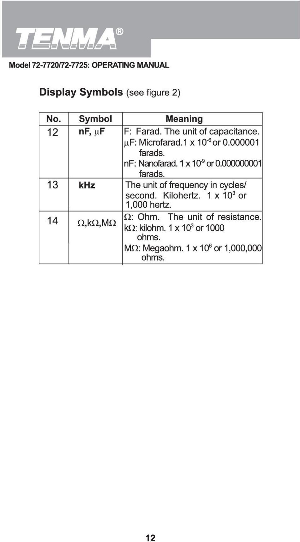
11
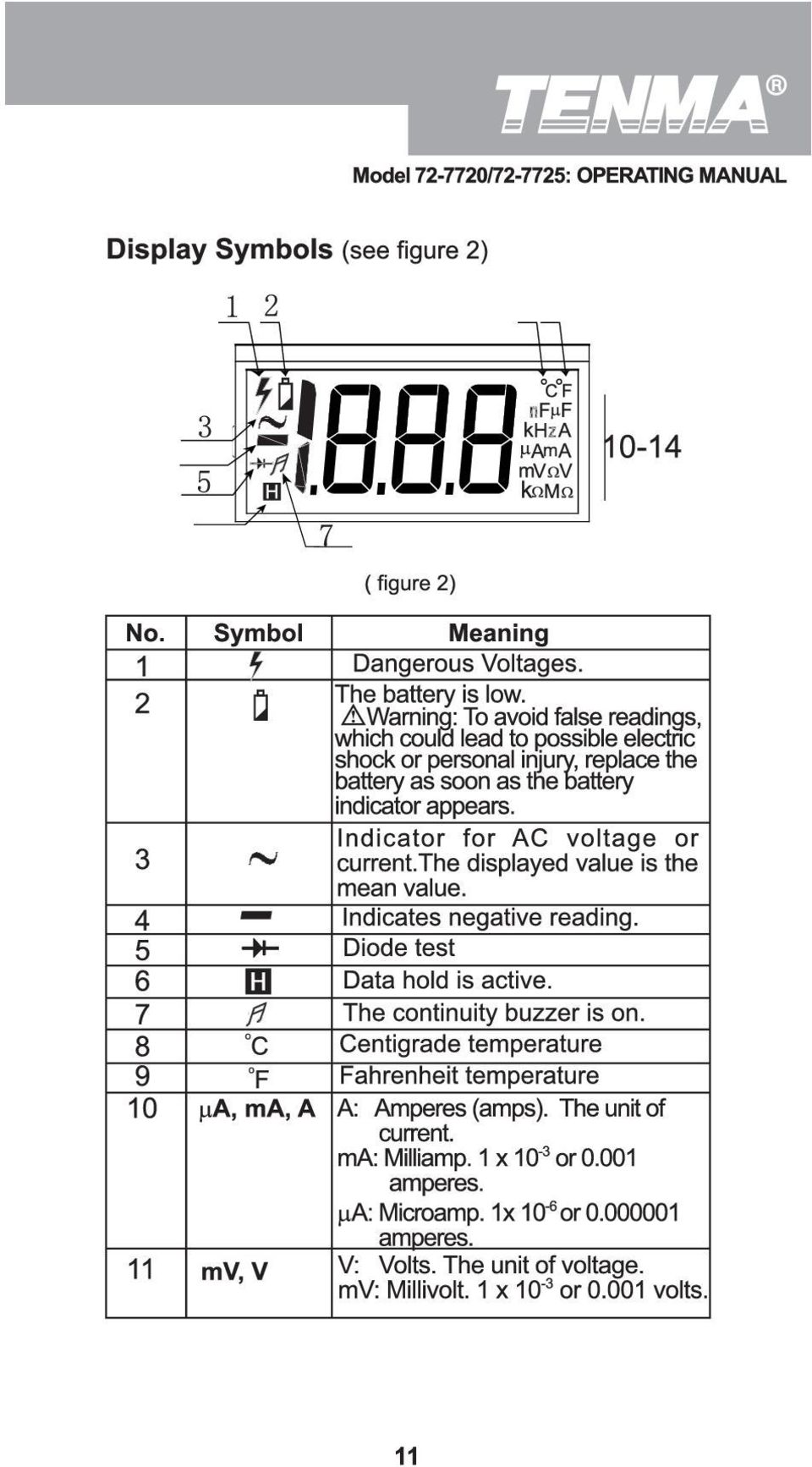
12
13

14

15

16

17 Measurement Operation(5) 2. Insert the red test lead into the µama ( Model ) or 20A terminal and the black test lead into the COM terminal. 3. Set the rotary switch to an appropriate measurement position in A range. 4. Break the current path to be tested. Connect the red test lead to the more positive side of the break and the black test lead to the more negative side of the break. 5. Turn on power to the circuit. The measured value shows on the display. Note If the value of current to be measured is unknown, use the maximum measurement position (20A) and 20A terminal, and reduce the range step by step until a satisfactory reading is obtained. When current measurement has been completed, disconnect the connection between the test leads and the circuit under test. D. AC Current Measurement (see figure 6) black red ( figure 6) 17

18 Measurement Operation(6) Warning Never attempt an in-circuit current measurement where the voltage between terminals and ground is greater than 60V. If the fuse burns out during measurement, the Meter may be damaged or the operator may be injured. Use proper terminals, function, and range for the measurement. When test leads are connected to the current terminals, do not place them in parallel across any circuit. Model : The AC current measurement has five measurement positions on the rotary switch: 200µA, 2mA, 20mA, 200mA and 20A. Model : The AC current measurement has three measurement positions on the rotary switch: 20mA, 200mA and 20A. To measure current, do the following: 1. Turn off power to the circuit.discharge all high-voltage capacitors. 2. Insert the red test lead into theµama ( Model ) or ma ( Model ) or 20A terminal and the black test lead into the COM terminal. 3. Set the rotary switch to an appropriate measurement position in A range. 4. Break the current path to be tested. Connect the red test lead to the more positive side of the break and the black test lead to the more negative side of the break. 5. Turn on power to the circuit. The measured value shows on the display. Note If the value of current to be measured is unknown, use the maximum measurement position (20A) and 20A terminal and reduce the range step by step until a satisfactory reading is obtained. When current measurement has been completed, disconnect the connection between the testing leads and the circuit under test. 18

19 Measurement Operation(7) E. Measuring Resistance (see figure 7) red black ( figure 7) Warning To avoid damage to the Meter or to the devices under test, disconnect circuit power and discharge all the high-voltage capacitors before measuring resistance. The resistance ranges are: Model : 200Ω, 2kΩ, 20kΩ, 200kΩ, 2MΩ, 20MΩand 200MΩ. Model : 200Ω, 2kΩ, 20kΩ, 200kΩ, 2MΩ and 200MΩ. To measure resistance, connect the Meter as follows: 1. Insert the red test lead into the VΩ terminal and the black test lead into the COM terminal. 2. Set the rotary switch to an appropriate measurement position inω range. 3. Connect the test leads across with the object being measured.the measured value shows on the display. Note The test leads can add 0.1Ωto 0.3Ω of error to the resistance measurement.to obtain precision readings in low-resistance, that is the range of 200Ω, shortcircuit the input terminals beforehand and record the reading obtained (called this reading as X). (X) is the additional resistance from the test lead. 19

20 Measurement Operation(8) For high resistance (>1MΩ), it is normal to take several seconds to obtain a stable reading. When there is no input, for example in open circuit condition, the Meter displays 1. When resistance measurement has been completed, disconnect the connection between the testing leads and the circuit under test. F. Model : Frequency Measurement (see figure 8) red black ( figure 8) Warning To avoid harm to you or damage to the Meter, do not attempt to measure voltages higher than 60V in DC or 30V rms in AC although readings may be obtained. When the frequency signal to be tested is higher than 30V rms, the Meter cannot guarantee accuracy of the measurement. The frequency measurement ranges are 2kHz and 20kHz. To measure frequency, connect the Meter as follows: 1. Insert the red test lead into the VΩ terminal and the black test lead into the COM terminal. 2. Set the rotary switch to an appropriate measurement position in khz range. 3. Connect the test leads across with the object being measured. The measured value shows on the display. 20
 red black ( figure 8) Warning To avoid harm to you or damage to the Meter, do not attempt to measure voltages higher than 60V in DC or 30V rms in AC")
21 Measurement Operation(9) Note When Hz measurement has been completed, disconnect the connection between the testing leads and the circuit under test. G. Model : Temperature Measurement (see figure 9) ( figure 9) Warning To avoid harm to you or damage to the Meter, do not attempt to measure voltages higher than 60V in DC or 30V rms in AC although readings may be obtained. The temperature measurement range is from -40 o C~ 1000 o C or -40 o F~1832 o F. To measure temperature, connect the Meter as follows: 1. Insert the red temperature probe into the V Ω terminal and the black temperature probe into the COM terminal. 2. Set the rotary switch to o C or o F. 3. Place the temperature probe to the object being measured. The measured value shows on the display. Note The Meter automatically displays the temperature value inside the Meter when there is no temperature probe connected. 21
22 Measurement Operation(10) The included temperature probe may only be used for measurment up to 250 o C For any mesaurement higher than that, the rod type temperature probe must be used. When temperature measeuremnet has been completed, disconnect the connection between the testing leads and te circuit under test. H.Capacitance Measurement (see figure 10) ( figure 10) Model :Capacitance measurement has four measurement positions on the rotary switch : 2nF, 20nF, 2µF and 100µF. Model : Capacitance measurement has four measurement positions on the rotary switch: 20nF, 200nF, 2µF and 100µF. To measure capacitance, connect the Meter as follows: 1. Insert the red test clip or red test lead into the VΩ terminal and the black test clip or black test lead into the µma ( Model: ) or ma ( Model: ) terminal. 2. Set the rotary switch to an appropriate measurement position in Fcx range. 3. Connect the test leads across with the object being measured. The measured value shows on the display. 22
23 Measurement Operation(11) Note When testing polarited capacitors, connect the red test lead to anode & black test lead to cathode If the capacitor is shorted or the capacitor value is overloaded, the LCD will display 1. To minimize the error, the test lead should be as short as possible. When the tested capacitor is greater than 30 µf, reading is for reference only. It is normal to take a while for zeroing when changing the measurement range. This process will not affect the accuracy of the final readings obtained. I. Measuring Diodes & Continuity Warning To avoid damage to the Meter or to the equipment under test, disconnect circuit power and discharge all high-voltage capacitors before measuring diodes and continuity. Testing Diodes Use the diode test to check diodes, transistors, and other semiconductor devices. The diode test sends a current through the semiconductor junction, and then measures the voltage drop across the junction. A good silicon junction drops between 0.5V and 0.8V. To test out a diode out of a circuit, connect the Meter as follows: 1. Insert the red test lead into the VΩ terminal and the black test lead into the COM terminal. 2. Set the rotary switch to. 3. For forward voltage drop readings on any semiconductor component, place the red test lead on the component s anode and place the black test lead on the component s cathode. The measured value shows on the display. 23
24 Measurement Operation(12) Note In a circuit, a good diode should still produce a forward voltage drop reading of 0.5V to 0.8V; however; the reverse voltage drop reading can vary depending on the resistance of other pathways between the probe tips. Connect the test leads to the proper terminals as said above to avoid error display. The LCD will display 1 indicating open-circuit for wrong connection. The unit of diode is Volt (V), displaying the positiveconnection voltage-drop value. When diode testing has been completed, disconnect the connection between the testing leads and the circuit under test. Testing for Continuity To test for continuity, connect the Meter as below: 1. Insert the red test lead into VΩ terminal and the black test lead into the COM terminal. 2. Set the rotary switch to. 3. Connect the test leads across with the object being measured. The buzzer sounds if the resistance of a circuit under test is less than 70Ω. The LCD displays the resistance value of a circuit under test. Note The LCD display 1 indicating the circuit being tested is open. When continuity testing has been completed, disconnect the connection between the testing leads and the circuit under test. 24
25 Sleep Mode Turning on the Auto Display Backlight The Meter has a built-in sensor. Therefore the Display Backlight turns on and off automatically depending on the brightness of the environment. 25
26 General Specifications Maximum voltage between any Terminals and Ground : 1000V rms. Fused Protection for ma Input Terminal : 0.5A, 250V fast type, 5x20mm. Fused Protection for 20A Input Terminal : Un-fused. Range : Manual ranging. Maximum Display : Display :1999. Mesaurement Speed : Updates 2~3 times/second. Temperature : Operating: 0 o C~40 o C (32 o F~104 o F); Storage : -10 o C~50 o C( 14 o F~122 o F). Relative Humidity : 0 o C~30 o C; 31 o C~40 o C. Altitude: Operating : 2000m; Storage : 10000m. Battery Type : 9V NEDA1604 or 6F22 or 006P. Low Battery : Display. Data Hold : Display Negative read : Display Overload : Display 1. Dimensions (HxWxL) : 165x80x38.3mm. Weight : Approx.275g (battery included). Safety/Compliances : IEC61010 CAT II 1000V overvoltage and double insulation standard. Certificate : 26
27 Accuracy Specifications(1) Accuracy: (a% reading + b digits),guarantee for 1 year. Operating temperature:23 o C 5 o C. Relative humidity:<75%. Temperature coefficient: 0.1 x (specified accuracy) / 1 o C. A. DC Voltage Range 200mV 2V 20V 200V 1000V Resolution 100µV 1mV 10mV 100mV 1V Accuracy (0.5%+1) (0.8%+2) Remark: Input impedance: 10MΩ Overload Protection 250VDCor ACrms. 1000V DC or 750V AC rms. B. AC Voltage Accuracy Range Resolution mV 100µV (1.2%+3) 2V 20V 200V 750V 1mV 10mV 100mV 1V (0.8%+3) (1.2%+3) Overload Protection 250V DC or AC rms 1000V DC or 750V AC rms. Remarks: Input impedance: 10MΩ. Frequency response: 40Hz~400Hz. Display effective value of sine wave (mean value response). 27
28 Accuracy Specifications(2) C. DC Current Range Resolution 20µA 2mA 20mA 200mA 20A 0.01µA 1µA 10µA 100µA 10mA Accuracy Overload Protection (0.8%+1) 0.5A. 250V fast type fuse, 5x20 (0.8%+1) mm (1.5%+1) (2%+5) Un-Fused Remarks: At 20A Range: For continuous measurement 10 seconds and interval not less than 15 minutes. Measurement voltage drop: Full range at 200mV. D. AC Current Range Resolution 200µA 2mA 20mA 200mA 20A 0.1µA 1µA 10µA 100µA 10mA Accuracy (1%+3) (1%+3) (1.8%+3) (3%+5) Overload Protection 0.5A. 250V fast type fuse, 5x20 mm Un-Fused Remarks: At 20A Range: For continuous measurement 10 seconds and interval not less than 15 minutes. Measurement voltage drop: Full range at 200mV. Frequency reaponse: 40Hz~400Hz Display effective value of sine wave (mean value response). 28
29 Accuracy Specifications(3) E. Resistance Test Range Resolution 200Ω 2kΩ 20kΩ 200kΩ 2MΩ 20MΩ 200MΩ 0.1Ω 1Ω 10Ω 100Ω 1kΩ 10kΩ 100kΩ Accuracy (0.8%+3) (0.8%+1) (1%+2) [5%(reading-10)+10] Overload Protection 250V DC or AC rms Remarks: Open circuit voltage: 700mV (At 200MΩ range, it is approx. 2.8V) At 200MΩ range, test lead is in short circuit, and it is normal to display 10 digits. During measurement, subtract the 10 digits from the reading. F. Model : Frequency Range Resolution Accuracy Overload Protection 2kHz 20kHz 1Hz 10Hz (2%+5) (1.5%+5) Remarks: Input Sensitivity: 200mV. 250V AC G. The Model : Temperature Range -40 o C~0 o C 0 o C~400 o C 400 o C~1000 o C -40 o F~32 o F 32 o F~752 o F 752 o F~1832 o F Resolution 1 o C 1 o F Accuracy (3%+3) (1%+3) 2.5% (3%+4) (1%+4) (1.5%+15) Overload Protection 250V AC 29
30 Accuracy Specifications(4) H. Capacitance Range Resolution 2nF 20nF 200nF 2µF 100µF Accuracy pF (4%+3) 10pF 0.1nF (4%+3) 1nF (4%+3) 0.1µF (5%+4) Overload Protection 250V AC Remarks:Testing signal:approx. 400Hz 40mV rms. When the tested capacitor is greater than 30 µf, reading is for reference only. I. Diodes and Continuity Test Range Resolution Input Protection Remark 1mV Open circuit voltage approx.2.8v 250V DC or AC 1Ω 30
31 Maintenance(1) This section provides basic maintenance information including battery and fuse replacement instruction. Warning Do not attempt to repair or service your Meter unless you are qualified to do so and have the relevant calibration, performance test, and service information. To avoid electrical shock or damage to the Meter, do not get water inside the case. A. General Service Periodically wipe the case with damp cloth and mild detergent. Do not use chemical solvent. To clean the terminals with cotton bar with detergent, as dirt or moisture in the terminals can affect readings. Turn the Meter OFF when it is not in use and take out the battery when not using for a long time. Do not store the Meter in place of humidity, high temperature, explosive, inflammable and strong magnetic field B. Replacing the Battery (see figure 11) (figure 11) 31
32 Maintenance(2) Warning To avoid false readings, which could lead to possible electric shock or personal injury,replace the battery as soon as the battery indicator To replace battery: appears. 1. Disconnect the connection between the test leads and the circuit under test, and move the test leads away from the input terminals of the Meter. 2. Turn the Meter OFF 3. Remove the rubber feet and screws from the battery compartment, and separate the battery compartment from the case bottom 4. Remove the battery from the battery compartment. 5. Replace the battery with a new 9V battery (NEDA 1604 or 6F22 or 006P). 6. Rejoin the battery compartment and the case bottom, and install the screw and rubber feet C. Replacing the Fuses Warning To avoid electrical shock, arc blast, personal injury or damage to the Meter, use specified fuses ONLY in accordance with the following procedure. To replace the Meter s fuse: 1. Disconnect the connection between the test leads and the circuit under test, and move the test leads away from the input terminals of the Meter. 2. Turn the Meter OFF. 3. Remove the rubber feet and screws from the case bottom, and separate the case bottom from the case top. 4. Remove the fuse by gently prying one end loose, and then take out the fuse from its bracket. 32
33 Model Model / : UT50A/B/C: OPERATING MANUAL Maintenance(3) 1. Install ONLY replacement fuses with the identical type and specification as follows and make sure the fuse is fixed firmly in the bracket. 0.5A. 250V fast type fuse, φ 5x20mm. 2. Rejoin the case bottom and the case top, and install the screw and rubber feet Replacement of fuses is seldom required. Burning of a fuse always results from the improper operation. ~ END ~ This operating manual is is subject to change without notice. 33
34 Tenma Test Equipment 405 S. Pioneer Blvd. Springboro,Ohio
Model UT33A: OPERATING MANUAL Table of Contents (1)
") Table of Contents (1) Title Overview Unpacking Inspection Safety Information Rules For Safe Operation International Electrical Symbols The Meter structure Functional Buttons LCD Display Measurement Operation
Table of Contents (1) Title Overview Unpacking Inspection Safety Information Rules For Safe Operation International Electrical Symbols The Meter structure Functional Buttons LCD Display Measurement Operation
Model UT201/202: OPERATING MANUAL. Table of Contents
 Table of Contents Title Overview Unpacking Inspection Safety Information Rules For Safe Operation International Electrical Symbols The Meter Structure Rotary Switch Functional Buttons The Effectiveness
Model UT33B/C/D: OPERATING MANUAL Table of Contents (1)
") Table of Contents (1) Title Overview Unpacking Inspection Safety Information Rules For Safe Operation International Electrical Symbols The Meter structure Functional Buttons Measurement Operation A. DC
Table of Contents (1) Title Overview Unpacking Inspection Safety Information Rules For Safe Operation International Electrical Symbols The Meter structure Functional Buttons Measurement Operation A. DC
UT202A Operating Manual. Contents
 Title Contents Page Overview Unpacking Inspection Safety Information Rules for Safe Operation International Electrical Symbols The Meter Structure Functional Buttons and auto power off Display Symbols
Model UT58A/B/C: OPERATING MANUAL
 Table of Contents Title Page Overview Unpacking Inspection Safety Information Rules For Safe Operation International Electrical Symbols The Meter Structure Rotary Switch Functional Buttons Display Symbols
Model UT60A: OPERATING MANUAL. Table of Contents. Page 3 4 5 6 8 9 10 11 14 17 17 17 19 19
 Table of Contents Title Overview Unpacking Inspection Safety Information Rules For Safe Operation International Electrical Symbols The Meter Structure Rotary Switch Functional Buttons Display Symbols Measurement
72-7730 72-7732 Intelligent Digital Multimeters
 72-7730 72-7732 Intelligent Digital Multimeters Model 72-7730/72-7732 OPERATING MANUAL TABLE OF CONTENTS CHAPTER TITLE PAGE 1. Before You Start Overview Inspection Safety Information Rules For Safe Operation
Model UT61A/61B/61C/61D/61E: OPERATING MANUAL. Table of Contents
 P/N:110401103671 Table of Contents Title Overview Unpacking Inspection Safety Information Rules For Safe Operation International Electrical Symbols The Meter Structure Rotary Switch Functional Buttons
User's Guide. True RMS Industrial Multimeter
 User's Guide 97650 True RMS Industrial Multimeter Ω C ã F ã 10A V µ 10A V ã ã ma A Introduction This meter measures AC/DC Voltage, AC/DC Current, Resistance, Capacitance, Frequency (electrical & electronic),
AutoRanging Digital MultiMeter
 Owner's Manual AutoRanging Digital MultiMeter Model No. 82139 CAUTION: Read, understand and follow Safety Rules and Operating Instructions in this manual before using this product. Safety Operation Maintenance
Auto-ranging Digital Multimeter 52-0052-2 INSTRUCTION MANUAL
 Auto-ranging Digital Multimeter 52-0052-2 INSTRUCTION MANUAL WARNING: READ AND UNDERSTAND THIS MANUAL BEFORE USING YOUR MULTIMETER. FAILURE TO UNDERSTAND AND COMPLY WITH WARNINGS AND OPERATING INSTRUCTIONS
Model UT71A/B OPERATING MANUAL
 Model UT71A/B OPERATING MANUAL CHAPTER TITLE PAGE 1. 2. Before You Start Overview Unpacking Inspection Safety Information Rules For Safe Operation International Electrical Symbols Getting Acquainted Turning
Manual Ranging MultiMeter
 Owner s Manual Manual Ranging MultiMeter Model 82345 CAUTION: Read, understand and follow Safety Rules and Operating Instructions in this manual before using this product.! Safety! Operation! Maintenance!
User Guide. Model 380260 Insulation Tester / Megohmmeter
 User Guide Model 380260 Insulation Tester / Megohmmeter Introduction Congratulations on your purchase of Extech s Insulation Tester/Megohmmeter. The Model 380260 provides three test ranges plus continuity
Model UT713 OPERATING MANUAL
 Model UT713 OPERATING MANUAL TABLE OF CONTENTS TITLE PAGE Introduction Unpacking Inspection Safety Information Turning the Calibrator On Simulating a Thermocouple Measuring a Thermocouple Simulating TC
10 Multimeter. Users Manual
 10 Multimeter Users Manual 1991-2001 Fluke Corporation, All rights reserved. Printed in USA All product names are trademarks of their respective companies. 10 MULTIMETER m m Mk SELECT RANGE OFF VDC VAC
IDEAL INDUSTRIES, INC. TECHNICAL MANUAL MODELS: 61-763 61-765
 IDEAL INDUSTRIES, INC. TECHNICAL MANUAL MODELS: 61-763 61-765 The Service Information provides the following information: Precautions and safety information Specifications Performance test procedure Calibration
i410/i1010 AC/DC Current Clamp
 /i1010 AC/DC Current Clamp Instruction Sheet Safety Information XW Read First: Safety Information To ensure safe operation and service of the current clamp, follow these instructions: Read all operating
7 FUNCTION DIGITAL MULTIMETER
 7 FUNCTION DIGITAL MULTIMETER 90899 OPERATING INSTRUCTIONS 3491 Mission Oaks Blvd., Camarillo, CA 93011 Visit our Web site at http://www.harborfreight.com Copyright 2004 by Harbor Freight Tools. All rights
DIGITAL MULTIMETER OPERATION MANUAL ITEM 98674 DIGITAL MULTIMETER CONTENTS
 CONTENTS ITEM 98674 OPERATION MANUAL CONTENTS 1. SAFETY INFORMATION 1 1.1 PRELIMINARY 1 1.2 DOS AND DON TS 2 1.3 SYMBOLS 3 1.4 MAINTENANCE 4 2. DESCRIPTION 6 2.1 NAMES OF PARTS 7 2.2 SWITCH, BUTTONS AND
HVAC Clamp Meter. Users Manual
 902 HVAC Clamp Meter Users Manual PN 2547887 May 2006 Rev. 1, 3/07 2006-2007 Fluke Corporation. All rights reserved. Printed in China. All product names are trademarks of their respective companies. LIMITED
1587/1577. Insulation Multimeters. Technical Data. Two powerful tools in one.
 1587/1577 Insulation Multimeters Technical Data Two powerful tools in one. The Fluke 1587 and 1577 Insulation Multimeters combine a digital insulation tester with a full-featured, true-rms digital multimeter
How To Use A Cdm250 Digital Multimeter
 User Manual CDM250 Digital Multimeter 070-6736-03 Copyright Tektronix, Inc. 1987. All rights reserved. Tektronix products are covered by U.S. and foreign patents, issued and pending. Information in this
Seven function digital multimeter
 Seven function digital multimeter 98025 Set up And Operating Instructions Distributed exclusively by Harbor Freight Tools. 3491 Mission Oaks Blvd., Camarillo, CA 93011 Visit our website at: http://www.harborfreight.com
User Guide. www.burntec.com. 4 wire Earth Resistance Tester Model GRT300
 User Guide 4 wire Earth Resistance Tester Model GRT300 Introduction Congratulations on your purchase of Extech s 4 Wire Earth Resistance Tester. The Model GRT300 has been designed and tested according
Owner s Manual & Safety Instructions
 Owner s Manual & Safety Instructions Save This Manual Keep this manual for the safety warnings and precautions, assembly, operating, inspection, maintenance and cleaning procedures. Write the product s
EPM3. Phase Sequence and Motor Rotation Tester. Users Manual
 EPM3 Phase Sequence and Motor Rotation Tester Users Manual 1 L1 L2 L3 2 3 A B C CAT 600V 3-PHASE TESTER 5 TEST M1 M2 BATT M3 EPM3 MOTOR ROTATION TESTER EPM3 MOTOR ROTATION DETERMINED WHILE FACING MOTOR
Instruction Manual. 2in1 LAN Tester & Multimeter. Model: LA-1011
 Instruction Manual 2in1 LAN Tester & Multimeter Model: LA-1011 1 Contents Introduction... Features... Safety Precautions.. Meter Description... Electrical Specification... Operation.. AutoRanging Multimeter.
The table below lists the symbols used on the Clamp and/or in this manual. Important Information. See manual.
 i800 AC Current Clamp Instruction Sheet Introduction The i800 AC Current Clamp, the Clamp, has been designed for use with multimeters, recorders, power analyzers, safety testers, etc., for accurate non-intrusive
Model 77 Series IV Digital Multimeter
 Model 77 Series IV Digital Multimeter Introduction XWWarning To avoid electric shock or injury, do not perform the performance tests or calibration adjustment procedures unless qualified to do so. The
Instruction Manual IDM 71/72/73 Digital Multimeter EN FR IT DE
 Instruction Manual IDM 71/72/73 Digital Multimeter EN FR IT DE Warning...................................... Caution.............................................. Safety Alert Symbol : READ and UNDERSTAND
AVO410. Digital multimeter Digitale Multimeter Multimèter numérique Multímetro digitales Digitale multimeter
 mm AVO410 Digital multimeter Digitale Multimeter Multimèter numérique Multímetro digitales Digitale multimeter User manual Bedienungsanleitung Manuel utilisateur Guía del usuario Gebruikershandleiding
Instructions A622 100 Amp AC/DC Current Probe 070-8883-03
 Instructions A622 100 Amp AC/DC Current Probe 070-8883-03 Revision A www.tektronix.com 070888303 Copyright Tektronix, Inc. All rights reserved. Tektronix products are covered by U.S. and foreign patents,
MEGGER 210170 Insulation & Low Resistance Tester
 MEGGER 210170 Insulation & Low Resistance Tester User Guide SAFETY WARNINGS Safety Warnings and Precautions must be read and understood before the instrument is used. They must be observed during use.
Ground Resistance Clamp On Tester
 USER MANUAL Ground Resistance Clamp On Tester MODEL 382357 Introduction Congratulations on your purchase of Extech s 382357 Ground Resistance Tester. This Clamp on device allows the user to measure ground
323/324/325. Calibration Manual. Clamp Meter
 323/324/325 Clamp Meter Calibration Manual February 2013 2012 Fluke Corporation. All rights reserved. Specifications are subject to change without notice. All product names are trademarks of their respective
1587/1577. Insulation Multimeters. Users Manual
 1587/1577 Insulation Multimeters Users Manual PN 2401027 April 2005 2005 Fluke Corporation. All rights reserved. Printed in USA All product names are trademarks of their respective companies. LIMITED WARRANTY
Multimeter with Temperature
 16 Multimeter with Temperature P Read First: Safety Information Instruction Sheet To ensure that the meter is used safely, follow these instructions: Do not use the meter if the meter or test leads appear
Agilent U1230 Series Handheld Digital Multimeters (DMMs)
") Agilent U1230 Series Handheld Digital Multimeters (DMMs) Data Sheet Retool your expectations with the new Agilent U1230 Series Handheld DMMsthe first to combine a built-in LED flashlight, both audible
Agilent U1230 Series Handheld Digital Multimeters (DMMs) Data Sheet Retool your expectations with the new Agilent U1230 Series Handheld DMMsthe first to combine a built-in LED flashlight, both audible
Owner s Manual & Safety Instructions
 Owner s Manual & Safety Instructions Save This Manual Keep this manual for the safety warnings and precautions, assembly, operating, inspection, maintenance and cleaning procedures. Write the product s
Table of Contents. The Basics of Electricity 2. Using a Digital Multimeter 4. Testing Voltage 8. Testing Current 10. Testing Resistance 12
 Table of Contents The Basics of Electricity 2 Using a Digital Multimeter 4 IDEAL Digital Multimeters An Introduction The Basics of Digital Multimeters is designed to give you a fundamental knowledge of
115C and 117C. True-rms Multimeters. Users Manual
 115C and 117C True-rms Multimeters Users Manual PN 2538695 July 2006, Rev. 1, 2/07 2006, 2007 Fluke Corporation, All rights reserved. Printed in China All product names are trademarks of their respective
Achat 115MA full-range speaker. user manual
 Achat 115MA full-range speaker user manual Musikhaus Thomann Thomann GmbH Hans-Thomann-Straße 1 96138 Burgebrach Germany Telephone: +49 (0) 9546 9223-0 E-mail: info@thomann.de Internet: www.thomann.de
User s manual FLIR VP50/VP52 Non-contact AC voltage detector
 User s manual FLIR VP50/VP52 Non-contact AC voltage detector User s manual FLIR VP50/VP52 #T559851; r. AD/ 9134/9134; en-us Table of contents 1 Disclaimers... 1 1.1 Copyright... 1 1.2 Quality assurance...
1. SAFETY INFORMATION
 RS-232 Sound Level Meter 72-860A INSTRUCTION MANUAL www.tenma.com 1. SAFETY INFORMATION Read the following safety information carefully before attempting to operate or service the meter. Use the meter
INTRODUCTION SAFETY PRECAUTIONS/
 Title Page No. INTRODUCTION..................................1 SAFTY PRCAUTIONS/WARNINGS.................1 SPCIFICATIONS................................3 CONTROLS AND INDICATORS......................6
User s Manual Before using the inverter, you need to read and save the safety instructions.
 User s Manual Before using the inverter, you need to read and save the safety instructions. STI SERIES (STI200, STI300, STI500, STI700, STI1000) Power Frequency Pure Sine Wave Inverter The information
TIG INVERTER INSTRUCTION MANUAL
 TIG INVERTER INSTRUCTION MANUAL Contents Warning General Description Block Diagram Main Parameters Circuit Diagram Installation and Operation Caution Maintenance Spare Parts List Troubleshooting 3 4 4
RS DIGITAL THERMOMETER
 RS DIGITAL THERMOMETER 1319A INSTRUCTION MANUAL C F MX MN AVG TITLE TABLE OF CONTENTS PAGE 1. INTRODUCTION... 1 2. SPECIFICATIONS... 1 3. NAME OF PARTS AND POSITIONS... 3 4. OPERATION INSTRUCTIONS... 5
Dual Display Digital Multimeter
 Dual Display Digital Multimeter GDM-8246 GW INSTEK PART NO. 82DM-82460MG1 This manual contains proprietary information, which is protected by copyrights. All rights are reserved. No part of this manual
162 CB CABLE TRACER. Filter Probe & Tone Generator INSTRUCTION MANUAL
 162 CB CABLE TRACER Filter Probe & Tone Generator INSTRUCTION MANUAL INDEX PAGE 1. INTRODUCTION... 1 2. FILTER PROBE... 1-3 3. TONE GENERATOR... 3-6 4. SPECIFICATION... 7-8 5. MAINTENANCE... 8 1. INTRODUCTION
Model 1756 Test Lead Kit
 Keithley Instruments 28775 Aurora Road Cleveland, Ohio 44139 1-888-KEITHLEY http://www.keithley.com Model 1756 Test Lead Kit Gerneral Purpose Test Lead Information Description These test leads allow you
T+ and T+ PRO Electrical Tester
 T+ and T+ PRO Electrical Tester Instruction Sheet Introduction The Fluke T+ and T+ PRO Electrical Testers (the Tester ) have the following features: AC and dc voltage measurement, 12 V to 600 V, with or
Ground Resistance Clamp-On Tester
 User s Manual Ground Resistance Clamp-On Tester MODEL 382357 Warranty EXTECH INSTRUMENTS CORPORATION (a FLIR company) warrants the basic instrument to be free of defects in parts and workmanship for one
ABCs of DMMs Multimeter features and functions explained Application Note
 ABCs of DMMs Multimeter features and functions explained Application Note Digital multimeters offer a wide selection of features. Choosing the right meter for the job can be challenging unless you know
Table of Contents. Page No.
 Table of Contents Title Page No. INTRODUCTION... 2 SAFETY PRECAUTIONS/S... 2 SPECIFICATIONS... 3 CONTROLS AND INDICATORS... 8 TESTING PROCEDURES... 10 AUXILIARY FUNCTIONS... 17 BATTERY AND FUSE REPLACEMENT...
Microwave Meter. Instruction Manual
 Microwave Meter 840046 Instruction Manual Microwave Meter 840046 Copyright 2009 by Sper Scientific ALL RIGHTS RESERVED Printed in the USA The contents of this manual may not be reproduced or transmitted
Integrating Sound Level Meter and Datalogger
 USER GUIDE Integrating Sound Level Meter and Datalogger Model 407780A Introduction Thank you for selecting the Extech Instruments Model 407780A. This device is shipped fully tested and calibrated and,
ECEN 1400, Introduction to Analog and Digital Electronics
 ECEN 1400, Introduction to Analog and Digital Electronics Lab 4: Power supply 1 INTRODUCTION This lab will span two lab periods. In this lab, you will create the power supply that transforms the AC wall
AMP-210 AMP-210-EUR AMP-220 AMP-220-EUR AMP-310 AMP-310-EUR AMP-320 AMP-320-EUR. 600A AC TRMS Clamp Multimeter. 600A AC / DC TRMS Clamp Multimeter
 AMP-210 AMP-210-EUR 600A AC TRMS Clamp Multimeter AMP-220 AMP-220-EUR 600A AC / DC TRMS Clamp Multimeter AMP-310 AMP-310-EUR 600A AC TRMS Clamp Multimeter AMP-320 AMP-320-EUR 600A AC / DC TRMS Clamp Multimeter
Example of use: Fuse for a solenoid valve. If the fuse is defective, no information is sent to the electronic component.
 Overview Switch and button modules The dimensions of the switch and button modules are adapted to the electronic components in the integral housing. The modules are equipped with the universal clip-on
INSTRUCTION MANUAL PLEASE READ ALL THE INSTRUCTIONS COMPLETELY BEFORE USE AND SAVE THIS MANUAL FOR FUTURE REFERENCE
 INSTRUCTION MANUAL PLEASE READ ALL THE INSTRUCTIONS COMPLETELY BEFORE USE Ver. 2.0 AND SAVE THIS MANUAL FOR FUTURE REFERENCE Table of Contents Unpacking... 3 About the CCRadio-EP... 4 Quick Start Guide...
Building the HVPS High Voltage Power Supply
 Introduction Building the HVPS High Voltage Power Supply Voltages higher than the LVPS provides kilovolts are needed in later experiments to get strong electric fields and to generate microwaves. The high-voltage
Hygro-Thermometer + InfraRed Thermometer Model RH101
 User's Guide Hygro-Thermometer + InfraRed Thermometer Model RH101 Introduction Congratulations on your purchase of the Extech Hygro-Thermometer plus InfraRed Thermometer. This device measures relative
Lab E1: Introduction to Circuits
 E1.1 Lab E1: Introduction to Circuits The purpose of the this lab is to introduce you to some basic instrumentation used in electrical circuits. You will learn to use a DC power supply, a digital multimeter
User's Guide. Digital Psychrometer. Model RH390. F C WBT Dew Point MAX MIN
 User's Guide Digital Psychrometer Model RH390 MAX MIN F C WBT Dew Point Introduction Congratulations on your purchase of the Extech RH390 Digital Psychrometer. This device measures Humidity, Air Temperature,
INSTRUCTION MANUAL IPM 3600 3 Phase Power Analyser EN FR IT DE ES
 INSTRUCTION MANUAL IPM 3600 3 Phase Power Analyser EN FR IT DE ES CONTENTS / EN CONTENTS Title Page I. SAFETY INFORMATION...1 II. INTRODUCTION...3 III. SPECIFICATIONS...4 3-1 Environmental Conditions...4
12 Volt 30 Amp Digital Solar Charge Controller
 12 Volt 30 Amp Digital Solar Charge Controller User s Manual WARNING Read carefully and understand all INSTRUCTIONS before operating. Failure to follow the safety rules and other basic safety precautions
HOW TO USE MULTIMETER. COMPILE BY: Dzulautotech
 HOW TO USE MULTIMETER COMPILE BY: Dzulautotech 1. GENERAL Electricity is absolutely necessary for an automobile. It is indispensable when the engine is started, the air fuel mixture is ignited and exploded,
8001782 Owner s Manual
 8001782 Digital Infrared Thermometer Owner s Manual Introduction This instrument is a portable, easy to use compact-size digital thermometer with laser sighting designed for one hand operation. The meter
RS Stock No. 724-4207 Instruction Manual RS-1340 Hot Wire Anemometer
 RS Stock No. 724-4207 Instruction Manual RS-1340 Hot Wire Anemometer EN FR IT DE ES CONTENTS / EN Title CONTENTS Page 1. SAFETY INFORMATION...1 2. INTRODUCTION...2 3. SPECIFICATIONS...3 4. PARTS & CONTROLS...4
Table of Contents. Title
 Table of Contents Title Page No. INTRODUCTION... 2 SAFETY PRECAUTIONS/WARNINGS... 2 SPECIFICATIONS... 3 CONTROLS AND INDICATORS... 8 TESTING PROCEDURES... 10 AUXILIARY FUNCTIONS... 17 BATTERY AND FUSE
Essential Electrical Concepts
 Essential Electrical Concepts Introduction Modern vehicles incorporate many electrical and electronic components and systems: Audio Lights Navigation Engine control Transmission control Braking and traction
5000V Graphical Megohmmeter Model 5070
 5000V Graphical Megohmmeter Model 5070 The Model 5070, the latest design in 5000V Megohmmeters, is the most innovative product in its class on the market today. The features and functions incorporated
Loop Calibration and Maintenance
 Loop Calibration and Maintenance Application Note Introduction Process instrumentation requires periodic calibration and maintenance to ensure that it is operating correctly. This application note contains
Kit 106. 50 Watt Audio Amplifier
 Kit 106 50 Watt Audio Amplifier T his kit is based on an amazing IC amplifier module from ST Electronics, the TDA7294 It is intended for use as a high quality audio class AB amplifier in hi-fi applications
Milwaukee USER MANUAL. Milwaukee. Smart DO Meter PORTABLE DISSOLVED OXYGEN METER MODEL: SM600. Authorized Dealer: ISMIL600 11/01
 Milwaukee Milwaukee USER MANUAL PORTABLE DISSOLVED OXYGEN METER MODEL: SM600 Smart DO Meter Authorized Dealer: ISMIL600 11/01 PROBE PREPARATION: The meter is supplied with a 9V battery. Slide off the battery
VOLTAGE/CURRENT CALIBRATOR ISO-TECH ILC-421
 VOLTAGE/CURRENT CALIBRATOR ISO-TECH ILC-421 TABLE OF CONTENTS 1. FEATURES... 1 2. SPECIFICATIONS... 1 2-1 General Specifications...1 2-2 Electrical Specifications... 2 3. FRONT PANEL DESCRIPTION... 4 3-1
MIT510/2, MIT520/2 and MIT1020/2
 99 Washington Street Melrose, MA 02176 Phone 781-665-1400 Toll Free 1-800-517-8431 Visit us at www.testequipmentdepot.com MIT510/2, MIT520/2 and MIT1020/2 Line supply or battery operated Digital/analog
DUAL%CHANNEL BROADBAND%LINEAR%AMPLIFIER Model&A800D
 ELECTRONICS AB DUAL%CHANNEL BROADBAND%LINEAR%AMPLIFIER Model&A800D & HIGH&VOLTAGE& FIXED&GAIN& BROADBAND & 800Vpp&60mA& 100x& DC&to&ca&200&kHz & LOW&OUTPUT&IMPEDANCE& HIGH&SLEW&RATE &
Multifunction Process Calibrator
 725 Multifunction Process Calibrator Product Overview PN 1549644 English January 2000 Rev.2, 8/05 2000-2005 Fluke Corporation. All rights reserved. Printed in USA All product names are trademarks of their
Thermistor Thermometer MODEL NO. 93210-00
 Thermistor Thermometer MODEL NO. 93210-00 Cole-Parmer Instrument Co. 625 East Bunker Court Vernon Hills, Illinois U.S.A. 60061-1844 (847) 549-7600 (847) 247-2929 (Fax) 800-323-4340 www.coleparmer.com e-mail:
Getting started with
 PART NO. CMA113 MADE IN CHINA 1. Measuring CAT II 2. Max. voltage 250V ~ 3. Max. current 71 Amp Getting started with Electricity consumption monitoring single phase for homes and some smaller light commercial
Multimeter. Users Manual. Mode d'emploi. Bedienungs-Handbuch. Manuale d'uso. Manual de Uso. For IEC 61010 CAT III Meters Only
 Users Manual Mode d'emploi 27 Multimeter Bedienungs-Handbuch Manuale d'uso Manual de Uso For IEC 61010 CAT III Meters Only October 1998 Rev.2, 12/03 1998-2003 Fluke Corporation. All rights reserved. Printed
www.elektroexpressz.hu
 www.elektroexpressz.hu 2013 1 UT10 SERIES / UT20 SERIES Modern Pocket - Size Digital Multimeters Pocket-Size Digital Multimeters UNI-T UT10A UT10A DC Voltage 400mV/4V/40V/300 ±(0.8%+1) AC Voltage 4V/40V/300V
Fluke 3000 FC Series Test Tools Technical Data
 Fluke 3000 FC Series Test Tools Technical Data Now compatible with Fluke Connect Mobile App Start building tomorrow s test tool system today with the Fluke 3000 FC Digital Multimeter. The new Fluke Connect
ADM1TE 5/30A DIN rail single phase two wire energy meter
 ADMTE 5/30A DIN rail single phase two wire energy meter. Safety instruction.2 Foreword.3 Performance criteria.4 Specifications.5 Basic errors.6 Description.7 Dimensions.8 Installation.9 Operating.0 Troubleshooting.
Mini Power Bank and Charger
 Mini Power Bank and Charger Owner s Manual Please read before using this equipment. Your charger is ETL listed to UL standards and meets all applicable FCC standards. WARNING: To reduce the risk of fire
DC POWER SUPPLY ALIMENTATION C.C.
 DC POWER SUPPLY ALIMENTATION C.C. ISO-TECH IPS 303A 201-3424 ISO-TECH IPS 601A 201-3446 82IP-303A0ME E1 SAFETY TERMS AND SYMBOLS These terms may appear in this manual or on the product: WARNING. Warning
Milwaukee USER MANUAL
 Milwaukee USER MANUAL PORTABLE DISSOLVED OXYGEN METER MODEL: MW600 Smart DO Meter PROBE PREPARATION: The meter is supplied with a 9V battery. Slide off the battery compartment cover on the back of the
Users Manual. ProcessMeter
 787 ProcessMeter Users Manual April 1997, Rev.3, 12/01 1997, 1898, 2000, 2001 Fluke Corporation, All rights reserved. Printed in U.S.A. All product names are trademarks of their respective companies. LIMITED
INSTRUCTION MANUAL. NC-500 NETcat Pro Wiring Tester
 INSTRUCTION MANUAL English...1 16 Français...17 32 Español...33 48 Deutsch...49 64 NC-500 NETcat Pro Wiring Tester Read and understand all of the instructions and safety information in this manual before
1. Scope This specification is applied to ICR18650. 2. Product Specification Table 1 No. Item Rated Performance Remark
 1. Scope This specification is applied to ICR18650. 2. Product Specification Table 1 No. Item Rated Performance Remark 1 Rated Capacity Typical Minimum 2 Nominal Voltage 3.7V 3 Voltage at end of Discharge
OPERATION MANUAL. Pen type, separate electrode SOIL PH METER Model : PH-220S
 Pen type, separate electrode SOIL PH METER Model : PH-220S Your purchase of this SOIL PH METER marks a step forward for you into the field of precision measurement. Although this METER is a complex and
RADIANT PLASMA 4700 Plasma Spark Generator
 RADIANT PLASMA 4700 Plasma Spark Generator Installation Guide / User Manual A S P A R K O F F R E S H A I R Aquapulser.com Contents 1 Introduction 2 1.1 About the Product....................................
Transistor Amplifiers
 Physics 3330 Experiment #7 Fall 1999 Transistor Amplifiers Purpose The aim of this experiment is to develop a bipolar transistor amplifier with a voltage gain of minus 25. The amplifier must accept input
PR-D9W. GB Version 1
 PR-D9W Version 1 Table of contents Important safety instructions... 2-3 Introduction... 4 Controls... 5-8 Using your weather alert radio for the first time... 9 Operating your radio Search tuning AM/FM...
Agilent U1270 Series Handheld Digital Multimeters
 Agilent U1270 Series Handheld Digital Multimeters Be Ready for Winter Data Sheet NEW Features OLED display with 2000:1 contrast ratio and 160 degrees viewing angle 3,4 30,000-count resolution Measure up
What is a multimeter?
 What is a multimeter? A multimeter is a devise used to measure voltage, resistance and current in electronics & electrical equipment It is also used to test continuity between to 2 points to verify if
Load Cell Troubleshooting
 VPG TRANSDUCERS Load Cells and Weigh Modules Technical Note VPGT-08 Scope Load cells are designed to sense force or weight under a wide range of adverse conditions; they are not only the most essential