Chapter 2 P-H Diagram Refrigeration Cycle Analysis & Refrigerant Flow Diagram
|
|
|
- Gabriel Damian Johnston
- 7 years ago
- Views:
Transcription
1 Chapter 2 P-H Diagram Refrigeration Cycle Analysis & Refrigerant Flow Diagram Copy Right By: Thomas T.S. Wan 温 到 祥 著 Sept. 3, 2008 All rights reserved Industrial refrigeration system design starts from P-H Diagram Refrigeration Cycle Analysis and Refrigerant Flow Diagram: (1) P-H Diagram Refrigeration Cycle Analysis. P-H Diagram is to analysis the feasibility of the refrigeration cycle, to calculate the thermodynamic properties of the refrigeration system. Use the P-H Diagram analysis, all the refrigerant flow rates and operating conditions at the design point for the system can be clearly determined. (2) Refrigerant Flow Diagram. Refrigerant Flow Diagram is show the equipment used for the system, to determine the refrigerant piping between the components; also to determine the pipe sizes, insulation requirement, to determine the pressure drops, suction superheat and etc. The Refrigerant Flow Diagram can be very simple and it also can be expanded to P&ID (Process and Instrumentation Diagram) if required. The Refrigerant Flow Diagram is to be read in conjunction with the P-H Diagram to get the entire picture of the system. P-H Diagram Analysis. FIG. 2-1 shows a typical P-H (Pressure-Enthalpy) diagram for R-22. FIG. 2-2 shows the idea refrigeration cycle imposed on the P-H diagram. FIG. 2-3 is the image of the refrigeration cycle taken out from FIG. 2-2, but only showing the related data for this idea refrigeration cycle. The vertical Pressure Axis and the horizontal Enthalpy Axis are omitted. The pressures and enthalpy data related to the cycle are shown on the P-H diagram. Evaporator - Line A-B-C is the evaporative temperature line. The Enthalpy point B to Enthalpy point C represents the NRE for the system. Compressor - The Compression line is C-D, it is a line of constant Entropy. The Head of Compression is H D H C (Btu/Lb.). Compression Head (or Adiabatic Head) is also
 Refrigerant Flow Diagram.")
2 expressed in Feet, that is (H D H C ) x 778. For actual compression, the compression no longer follows adiabatic line and it follows polytropic function as indicated by the line C-D in FIG Condensing - The Condenser (Heat rejection) line is D-E or D -E for actual case. Total heat rejection from the condenser is the sum of heat absorbed from the
 line is D-E or D -E for actual case.")
3 - 14 -

4 evaporator plus the power input into the system. Expansion - The line representing the expansion is E-B. The operating conditions for the refrigeration system (at no loses) read from the P-H Diagram FIG. 2-3 are as the following: Condensing Temperature (CT): 110 Evaporative Temperature (ET): 10 Condensing Pressure: Psia Evaporative Pressure: Psia

5 Compressor Suction Temperature: 10 Compressor Suction Pressure: Psia Compressor Discharge Pressure: Pisa Compressor Suction Enthalpy: Btu/Lb. Compressor Discharge Enthalpy: Btu/Lb. Refrigerant Liquid Enthalpy: Btu/Lb. Compressor Suction Entropy: For more accurate calculation, it is suggested that all the data are to be taken out from the Refrigerant Property Table or from a Computer Software. Expansion (Throttling Process) and Flash Gas: From FIG. 2-3, when the refrigerant liquid leaves the condenser at point E ; it is a high pressure and high temperature liquid. Through the expansion valve, the liquid is throttling down to point B. Under this constant enthalpy process, portion of the liquid is evaporated to cool the liquid down to the temperature at the evaporative pressure line A-C. The percent of the Flash Gas is calculated as the following: H B H A Percent of Flash Gas = x 100 H C H A Net Refrigerant Effect: The remainder amount of the liquid excluding the Flash Gas in the evaporator is the useful effective liquid for refrigeration; the enthalpies difference between C-B is the Net Refrigerating Effect (NRE) as shown in the FIG Therefore: NRE = Enthalpy at point C Enthalpy at point B = H C H B (Btu/Lb.) The enthalpy of H B is the same as the enthalpy of H E because adiabatic process of Throttling, Therefore: NRE = H C H E (Btu/Lb.) Refrigerant Flow Determination: Refrigeration Ton (TR) is the unit of heat absorbed from evaporator, which is to absorb 12,000 Btu/Hr (or 200 Btu/Min) from the product or the process. The amount of refrigerant flow required to absorb one TR through the evaporator is determined as the following: 200 Flow = x TR NRE
 and Flash Gas: From FIG. 2-3, when the refrigerant liquid leaves the condenser at point E ; it is a high pressure and high temperature liquid.")
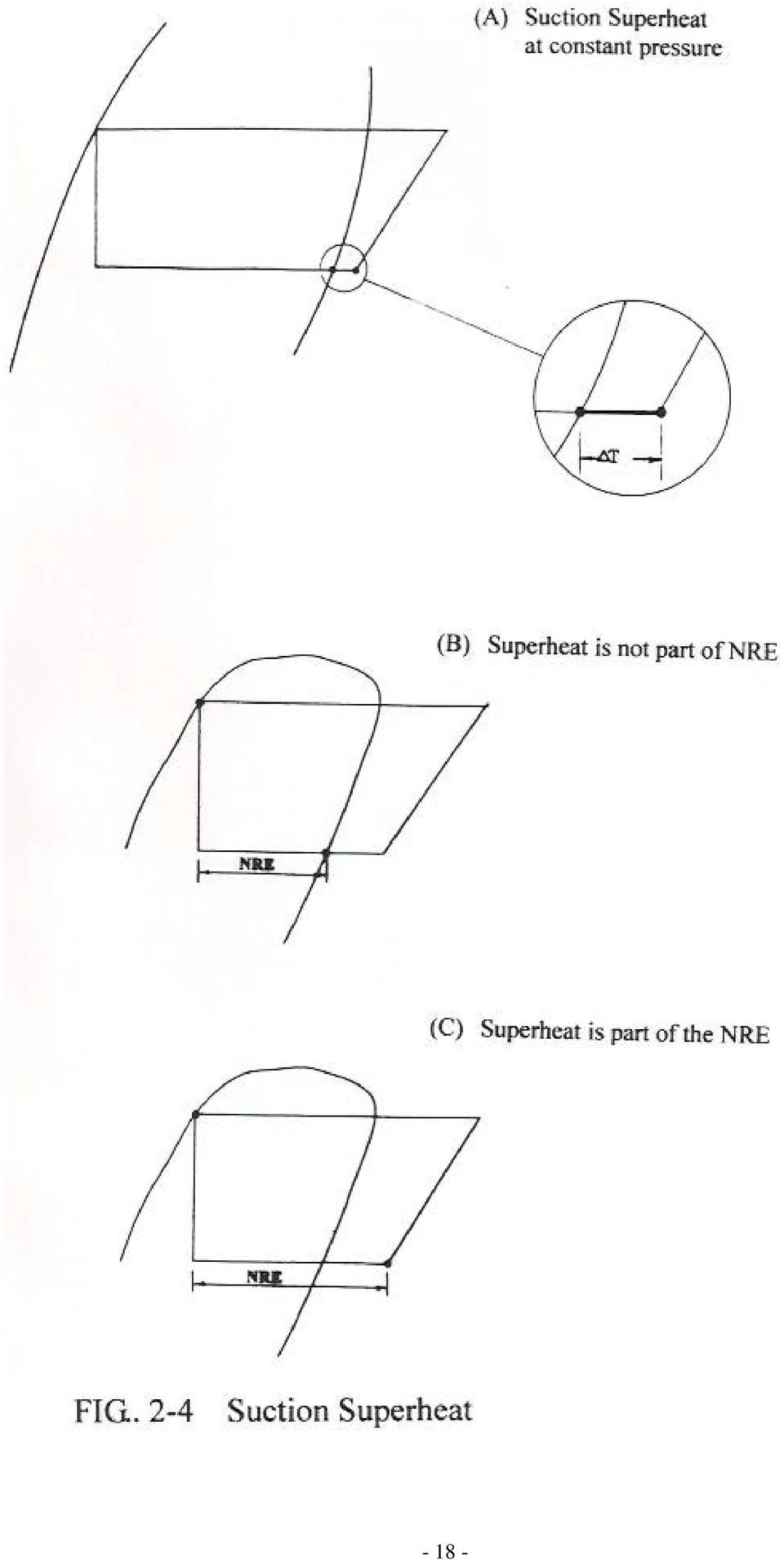
6 Where: Flow: Refrigerant Flow, Lbs/Min. 200: Heat removal, Btu/Min. NRE: Net Refrigeration Effect, Btu/Lb. TR: Tons of Refrigeration. NRE = H C H E, Therefore: 200 Flow = H C H E - x TR Suction Gas Superheat: In the real world, the suction gas at the inlet of the compressor is always superheated. The possible sources of superheat are the heat gain from inside of the heat exchanger, suction piping, suction and liquid heat exchanger if used, and compressor casing. Superheat increases the Entropy of suction gas and increases the compression head for the compressor. The suction superheat is represented by the horizontal constant pressure line on the P-H diagram in FIG Usually, the suction superheat is not considered as part of the NRE, unless the heat exchanger is purposely designed for it as shown in the case (C) of FIG Too much suction superheat is not desirable for the refrigeration system due to following reasons: (1) Higher suction entropy, higher power consumption for the compressor. (2) Increases the suction gas volume, increases the compressor size. (3) Higher compressor discharge temperature. Some of the systems, the suction superheat is extremely high due to the special design of the process heat exchanger. If it is the case, it might be justify by quenching the suction gas with refrigerant liquid

7 - 18 -
8 Suction Pressure Drop: Suction pressure drop is represented by the vertical line as shown in the P-H diagram of FIG Suction pressure drop must be allowed for compressor selection. Pressure drop from the evaporator to the compressor suction exists because of the following: (A) The suction pipe line pressure drops including valves, fittings and suction trap. (B) Suction valve, strainer and check valve for the compressor. (C) Suction gas acceleration. (D) Evaporator pressure drop. Too much suction pressure drop allowance would increase the size of the compressor and increase the design HP. But, too small suction pressure drop would increase the size of the suction piping, fittings and insulation. Therefore, the design allowance for the suction pressure drop should be economically balanced out with the cost for the piping, valves sizes and insulation. It is important that the suction pressure drop allowance should be expressed in terms of pressure in Psi, not the equivalent of saturated temperature of or C. The value of aδp for 2~3 is much smaller at lower ET than at higher ET. Suction Penalties: Suction penalty is the combination of suction superheat and suction pressure drop as shown in FIG Therefore, the suction penalty is not a horizontal, nor a vertical line. The correct expression shall be a slope as shown in the P-H Diagram. Discharge Penalty: Compressor discharge pressure is to be higher than the condensing pressure to overcome the pressure resistances in the discharge line. This pressure difference (ΔP) is shown in the P-H Diagram of FIG Too much discharge pressure drop allowed would increase the power consumption of the compressor. But, too small pressure drop allowance might increase the size of discharge piping and fittings. In any case, the discharge penalty should be allowed for the compressor selection for the proper function of the refrigeration system. For screw compressor application, theδp is usually larger than the reciprocating and centrifugal compressors. TheΔP for air cooled or evaporative condenser is larger than the water cooled condenser. Effect of Compressor Suction and Discharge Penalties: FIG. 2-8 shows the P-H Diagram for the refrigeration system with the suction and discharge penalties. The compression head which is with penalties (shown in dotted line) is larger than the one without penalties

9 - 20 -

10 - 21 -

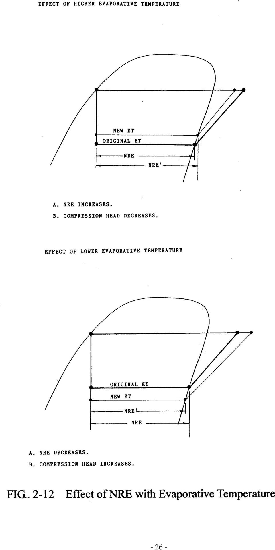
11 FIG. 2-9 shows the Typical P-H Diagram for a Screw System with liquid subcooling economizer; the diagram shows the suction and the discharge penalties which are usually encountered by screw compressor in a refrigeration system. Both discharge and suction penalties must be included for system design. It exists in the real world. The refrigeration capacity of the system would be under design as much as 10 to 15%, if the compressor is only rated for saturated CT and saturated ET without penalties. Liquid Subcooling: FIG (A) shows the Liquid Subcooling on the P-H diagram. If a smaller degree of liquid Subcooling is required by the application, it could be obtained by using cooling water. However, for larger degree of subcooling, it is necessary to include a liquid subcooler. Liquid Subcooling is one the methods to increase the NRE as shown in the FIG (B). Also, it is used to ensure the liquid supplied to the evaporator is free of flash gas as required by the application, particularly where the liquid line of the installation is with vertical lift. The relationships Between CT, ET and NRE: The P-H Diagram of FIG shows the cases of: 1.0 NRE decreases and compression head increases when the CT is higher. 2.0 The NRE increases and compression head decreases when the CT is lower. The P-H Diagram of FIG shows the cases of: 1.0 NRE increases and compression head decreases when the ET is higher. 2.0 The NRE getting smaller and compression head increase at lower ET. The NRE is changing all the times during system operation even at the full load condition. Flash Intercooling (Auto-Refrigeration): The flash intercooling is also a throttling process. A saturated liquid is flashed from a higher pressure at point E (FIG. 2-13) through a constant enthalpy process, down to a lower saturated temperature point B. Portion of the liquid is evaporated to cool the remainder liquid; this flash intercooling function is also called auto-refrigeration. The percent of the Flash Gas is calculated as the following: H B H A Percent of Flash Gas = x 100 H C H A Take an example for the case of flash intercooing shown in the P-H diagram of FIG. 2-13, the refrigerant is R-22, the enthalpy for each point is shown, if a flow of
 shows the Liquid Subcooling on the P-H diagram. If a smaller degree of liquid Subcooling is required by the application, it could be obtained by using cooling water.")
12 - 23 -

13 - 24 -

14 - 25 -

15 - 26 -
16 Lbs/Min liquid at 105 is throttling through a float valve down to a pressure of 10 saturated level; the gas and liquid flow at the 10 interstage level are as the following: Flash Gas Flow = x = Lbs/Min Liquid Flow at 10 = = Lbs/Min Power Consumption Calculation: For power consumption calculation, the enthalpy point for compressor suction and

17 discharge should include the penalties. Therefore, the compression head shall be H 2 and H 1 instead of H 2 and H 1 as shown in FIG The compression head shall be in Ft. instead of Btu/Lb for power consumption calculation: Head = (H 2 H 1 ) x 778 = Ft. Flow x Head Compressor HP = x E ff Where: Flow: Refrigerant Flow, Lbs/Min. Head: Compression Head, Ft. Compressor Overall Efficiency E ff Refrigerant Flow Diagram The main purpose of having Refrigerant Flow Diagram is to show: (a) Refrigerant flows and the operating conditions for the system. (b) The piping connections between main components for the refrigeration system. (c) Type of compressor, condenser, evaporator and etc. are used for the system. (d) Valves and other accessories for the system. (e) Other important associate components such as suction trap, oil separator and etc. for the proper function of the system. The Refrigerant Flow Diagram can be very simple just to show the main piping arrangement between the major components or could be complicated as P&ID. FIG shows a simple Refrigerant Flow Diagram and the correspondent P-H Diagram for the system. The P-H Diagram is showing part of the operating conditions for the refrigeration cycle. The Refrigerant Flow Diagram shown in FIG is a simple diagram and yet it conveys the messages of the following: A. It is a brine chilling refrigeration system. B. The compressor is a screw and it is completed with oil separator. C. Compressor is with suction stop valve, strainer and check valve. D. Discharge check and stop valve are used. E. It is with a water cooled, horizontal shell-and-tube condenser. F. The condenser is with a Marine Water Box. G. DX type brine chiller is used with expansion valve, solenoid valve, strainer and check valve. H. High pressure receiver with full length sight glass. I. Receiver equalizer
 Refrigerant flows and the operating conditions for the system.")
18 J. System drier-filter and liquid sightglass. K. Charging, purge valves and pressure relief valves

19 - 30 -
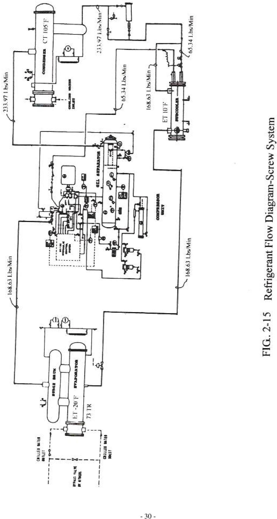
20 Summary of P-H Analysis and Refrigerant Flow Diagram The FIG is the typical Refrigerant Flow Diagram. FIG is the typical P-H Diagram for a refrigeration system. The Refrigerant Flow Diagram shows that the refrigeration system is a screw brine chilling with water cooled condenser, liquid subcooling economizer and the evaporator is a shell-and-tube flooded design with surge drum; water cooled oil cooling system is also shown for the screw compressor. For practical use purpose, the P-H Diagram and the Refrigerant Flow Diagram shown in FIG and FIG are well enough for system design application

Open Cycle Refrigeration System
 Chapter 9 Open Cycle Refrigeration System Copy Right By: Thomas T.S. Wan 温 到 祥 著 Sept. 3, 2008 All rights reserved An open cycle refrigeration system is that the system is without a traditional evaporator.
UNIT 2 REFRIGERATION CYCLE
 UNIT 2 REFRIGERATION CYCLE Refrigeration Cycle Structure 2. Introduction Objectives 2.2 Vapour Compression Cycle 2.2. Simple Vapour Compression Refrigeration Cycle 2.2.2 Theoretical Vapour Compression
HVAC and REFRIGERATION
 This is a preview. Some pages have been omitted. PE principles and practice prracticce of engineering mechanical: HVAC and REFRIGERATION sample questions + solutions Copyright 2011 by NCEES. All rights
How To Design A Refrigeration System
 AIRAH Refrigeration (in HVAC) Back to Basics For the First Time Terms of Reference What this session is NOT about Detailed Refrigeration Design Detailed analysis of various Refrigants properties Comparison
UNDERSTANDING REFRIGERANT TABLES
 Refrigeration Service Engineers Society 1666 Rand Road Des Plaines, Illinois 60016 UNDERSTANDING REFRIGERANT TABLES INTRODUCTION A Mollier diagram is a graphical representation of the properties of a refrigerant,
Lesson. 11 Vapour Compression Refrigeration Systems: Performance Aspects And Cycle Modifications. Version 1 ME, IIT Kharagpur 1
 Lesson Vapour Compression Refrigeration Systems: Performance Aspects And Cycle Modifications Version ME, IIT Kharagpur The objectives of this lecture are to discuss. Performance aspects of SSS cycle and
COMMERCIAL HVAC EQUIPMENT. Condensers and Cooling Towers
 COMMERCIAL HVAC EQUIPMENT Condensers and Cooling Towers Technical Development Programs (TDP) are modules of technical training on HVAC theory, system design, equipment selection and application topics.
REFRIGERATION (& HEAT PUMPS)
") REFRIGERATION (& HEAT PUMPS) Refrigeration is the 'artificial' extraction of heat from a substance in order to lower its temperature to below that of its surroundings Primarily, heat is extracted from
REFRIGERATION (& HEAT PUMPS) Refrigeration is the 'artificial' extraction of heat from a substance in order to lower its temperature to below that of its surroundings Primarily, heat is extracted from
Characteristics of Evaporators
 Characteristics of Evaporators Roger D. Holder, CM, MSME 10-28-2003 Heat or Energy In this paper, we will discuss the characteristics of an evaporator coil. The variance of the operational condenses of
It will be available soon as an 8.5 X 11 paperback. For easier navigation through the e book, use the table of contents.
 The System Evaluation Manual and Chiller Evaluation Manual have been revised and combined into this new book; the Air Conditioning and Refrigeration System Evaluation Guide. It will be available soon as
Chapter 3.4: HVAC & Refrigeration System
 Chapter 3.4: HVAC & Refrigeration System Part I: Objective type questions and answers 1. One ton of refrigeration (TR) is equal to. a) Kcal/h b) 3.51 kw c) 120oo BTU/h d) all 2. The driving force for refrigeration
ASHRAE Boston Chapter Meeting Designing AC Refrigeration Systems Lessons Learned February 11, 2014
 ASHRAE Boston Chapter Meeting Designing AC Refrigeration Systems Lessons Learned February 11, 2014 Explanation of the refrigeration cycle. Compressors. Benefits and operating characteristics. -Reciprocating
Fundamentals of Mechanical Refrigeration Systems
 PDHonline Course M244 (4 PDH) Fundamentals of Mechanical Refrigeration Systems Instructor: A. Bhatia, B.E. 2012 PDH Online PDH Center 5272 Meadow Estates Drive Fairfax, VA 22030-6658 Phone & Fax: 703-988-0088
COMMERCIAL HVAC CHILLER EQUIPMENT. Air-Cooled Chillers
 COMMERCIAL HVAC CHILLER EQUIPMENT Air-Cooled Chillers Technical Development Programs (TDP) are modules of technical training on HVAC theory, system design, equipment selection and application topics. They
Refrigeration Basics 101. By: Eric Nelson
 Refrigeration Basics 101 By: Eric Nelson Basics Refrigeration is the removal of heat from a material or space, so that it s temperature is lower than that of it s surroundings. When refrigerant absorbs
How To Calculate The Performance Of A Refrigerator And Heat Pump
 THERMODYNAMICS TUTORIAL 5 HEAT PUMPS AND REFRIGERATION On completion of this tutorial you should be able to do the following. Discuss the merits of different refrigerants. Use thermodynamic tables for
AIR CONDITIONING TECHNOLOGY
 AIR CONDITIONING TECHNOLOGY PART 9 Water Cooled Condensers & Cooling Towers IN LAST month s article we looked at how Air Cooled Condensers are used to transfer the total heat of rejection from the air
A/C refrigerant system, overview
 Page 1 of 19 87-18 A/C refrigerant system, overview A/C refrigerant system, identification Typical A/C refrigerant system with expansion valve and receiver drier 1 - Evaporator 2 - Expansion valve 3 -
Low GWP Replacements for R404A in Commercial Refrigeration Applications
 Low GWP Replacements for R404A in Commercial Refrigeration Applications Samuel YANA MOTTA, Mark SPATZ Honeywell International, 20 Peabody Street, Buffalo, NY 14210, Samuel.YanaMotta@honeywell.com Abstract
Data Realty Colocation Data Center Ignition Park, South Bend, IN. Owner: Data Realty Engineer: ESD Architect: BSA LifeStructures
 Data Realty Colocation Data Center Ignition Park, South Bend, IN Owner: Data Realty Engineer: ESD Architect: BSA LifeStructures Project Overview Data Realty is a data center service provider for middle
Troubleshooting an Air Conditioning system. R D Holder Eng. Roger D Holder MSME
 Troubleshooting an Air Conditioning system R D Holder Eng. Roger D Holder MSME Troubleshooting of an air conditioning system is a step by step procedure. I have found that a 4 step procedure is the best
2004 Standard For Performance Rating Of Positive Displacement Refrigerant Compressors And Compressor Units
 2004 Standard For Performance Rating Of Positive Displacement Refrigerant Compressors And Compressor Units ANSI/AHRI Standard 540 (formerly ARI Standard 540) IMPORTANT SAFETY RECOMMENDATIONS ARI does not
Ground-breaking conversion of critical Data Room WaterChiller from R22 to R422D / MO29
 Ground-breaking conversion of critical Data Room WaterChiller from R22 to R422D / MO29 A refrigerant retrofit project, involving the conversion of a large Data Room cooling system from R22 to R422D (DuPont
PERFORMANCE ANALYSIS OF VAPOUR COMPRESSION REFRIGERATION SYSTEM WITH R404A, R407C AND R410A
 Int. J. Mech. Eng. & Rob. Res. 213 Jyoti Soni and R C Gupta, 213 Research Paper ISSN 2278 149 www.ijmerr.com Vol. 2, No. 1, January 213 213 IJMERR. All Rights Reserved PERFORMANCE ANALYSIS OF VAPOUR COMPRESSION
COURSE TITLE : REFRIGERATION AND AIR CONDITIONING COURSE CODE : 4029 COURSECATEGORY : A PERIODS/WEEK : 5 PERIODS/SEMESTER : 90 CREDITS : 4 OBJECTIVES
 COURSE TITLE : REFRIGERATION AND AIR CONDITIONING COURSE CODE : 4029 COURSECATEGORY : A PERIODS/WEEK : 5 PERIODS/SEMESTER : 90 CREDITS : 4 TIME SCHEDULE MODULE TOPICS PERIODS 1 Introduction 22 Principles
DESIGN STANDARDS SECTION 23 60 00
 PART 1 - GENERAL 1.01 Work included: A. Piping, tubing and fittings. B. Piping specialties. C. Special duty valves. D. Refrigerants. E. Chillers. F. Refrigerant monitors. 1.02 General requirements: A.
Engineering Recommendation on: Accumulators Revised 6-17-99 Issued January 10, 1979 Page 1 of 7
 Issued January 10, 1979 Page 1 of 7 Accumulators have long been recognized by the industry as an effective means of maintaining good system balance by storing excess refrigerant as the condenser or evaporator
SECTION 5 COMMERCIAL REFRIGERATION UNIT 22 CONDENSERS
 SECTION 5 COMMERCIAL REFRIGERATION UNIT 22 CONDENSERS UNIT OBJECTIVES After studying this unit, the reader should be able to explain the purpose of the condenser in a refrigeration system. describe differences
POLICY BULLETIN Tecumseh Compressor Company Compressor Group
 to Bulk Milk Coolers and Other System Page 1 of 5 Overall reliability can be enhanced if there exists a complete understanding of the features, system design, installation requirements, processing, charging
High Pressure Ammonia Systems New Opportunities
 Purdue University Purdue e-pubs International Refrigeration and Air Conditioning Conference School of Mechanical Engineering 2010 High Pressure Ammonia Systems New Opportunities Andy Pearson Star Refrigeration
Table V. Troubleshooting Checklist for Refrigeration Systems. Air or non-condensable gas in system. Inlet water warm.
 Table V Troubleshooting Checklist for Refrigeration Systems TROUBLE POSSIBLE CAUSE CORRECTIVE MEASURE High condensing pressure. Low condensing pressure. Air or non-condensable gas in system. Inlet water
Troubleshooting HVAC/R systems using refrigerant superheat and subcooling
 Troubleshooting HVAC/R systems using refrigerant superheat and subcooling Application Note Troubleshooting and servicing refrigeration and air conditioning systems can be a challenging process for both
Commercial CO2 Refrigeration Systems. Guide for Subcritical and Transcritical CO2 Applications
 Commercial CO2 Refrigeration Systems Guide for Subcritical and Transcritical CO2 Applications 2 Contents Chapter 1. Introduction 4 Chapter 2. CO 2 Basics and Considerations as a Refrigerant 5 Section 1.
8. Refrigeration. 4. Liquid. Refrigerant. 4. Liquid Refrigerant. Figure 8.1 Refrigeration system layout (single stage)
") 2. Vapor 8. Refrigeration 4. Liquid 3. Condenser 5. Receiver 4. Liquid 1. Compressor 6. Throttling Device 12. Electricity 2. Vapor 8. Recirculator 4. Liquid 7. Liquid/Vapor 7. Liquid/Vapor 10. Warm Air
2. Vapor 8. Refrigeration 4. Liquid 3. Condenser 5. Receiver 4. Liquid 1. Compressor 6. Throttling Device 12. Electricity 2. Vapor 8. Recirculator 4. Liquid 7. Liquid/Vapor 7. Liquid/Vapor 10. Warm Air
Heat Recovery In Retail Refrigeration
 This article was published in ASHRAE Journal, February 2010. Copyright 2010 American Society of Heating, Refrigerating and Air-Conditioning Engineers, Inc. Posted at www.ashrae.org. This article may not
SPLIT SYSTEMS A PRIMER. By: Thomas Legutko and Michael Taylor Carrier Corporation Syracuse, New York
 SPLIT SYSTEMS A PRIMER By: Thomas Legutko and Michael Taylor Carrier Corporation Syracuse, New York September 2000 TABLE OF CONTENTS INTRODUCTION...2 SPLIT SYSTEM BASICS...3 Evaporator...3 Compressor...4
CONTAMINANT REMOVAL FROM CENTRIFUGAL SYSTEMS
 CONTAMINANT REMOVAL FROM CENTRIFUGAL SYSTEMS BULLETIN 240-10-3 June 2004 Supersedes June 1983 Many centrifugal systems get little maintenance. As a result they operate with the refrigerant highly contaminated
Increasing the evaporation temperature with the help of an internal heat exchanger
 Increasing the evaporation temperature with the help of an internal heat exchanger A. TAMBOVTSEV (a), H. QUACK (b) (a,b) Technische Universität Dresden, D-01062, Dresden, Germany (a) Fax: (+49351) 463-37247,
Geothermal Alliance of Illinois. TXVs Theory and Fundamentals John Haug Senior Application Engineer Emerson Climate Technologies - Flow Controls
 Geothermal Alliance of Illinois TXVs Theory and Fundamentals John Haug Senior Application Engineer Emerson Climate Technologies - Flow Controls Thermal Expansion Valve Topics Anatomy Operation Terms &
Thermal Coupling Of Cooling and Heating Systems
 This article was published in ASHRAE Journal, February 2011. Copyright 2011 American Society of Heating, Refrigerating and Air-Conditioning Engineers, Inc. Posted at www.ashrae.org. This article may not
Why and How we Use Capacity Control
 Why and How we Use Capacity Control On refrigeration and air conditioning applications where the load may vary over a wide range, due to lighting, occupancy, product loading, ambient weather variations,
Skills Canada National Competition Instructions and Competition Details 38 Refrigeration and Air Conditioning / Post - Secondary May 27-30, 2015 -
 Skills Canada National Competition Instructions and Competition Details / Post - Secondary May 27-30, 2015 - Saskatoon 1. Test Project Details This project is designed to test the range of skills used
Indoor coil is too warm in cooling mode or too cold in heating mode. Reversing valve or coil thermistor is faulty
 Codes Room Air Conditioner range: Indoor unit alarm s If timer lamp flashes for 1 second on, 1 second off, this indicates pre heating on the coil during heating mode and is not an error. If timer lamp
Central Air Conditioning Plants
 Central Air Conditioning Plants In our department, these plants (Air cooled or water cooled) are commonly available above 10 TR up to 100 TR. These types of plants are more suitable for large installations
DEVELOPMENT OF A TWIN SCREW EXPRESSOR AS A THROTTLE VALVE REPLACEMENT FOR WATER-COOLED CHILLERS
 DEVELOPMENT OF A TWIN SCREW EXPRESSOR AS A THROTTLE VALVE REPLACEMENT FOR WATER-COOLED CHILLERS J J Brasz, Carrier Corporation, Syracuse, NY, 13221, USA joost.j.brasz@carrier.utc.com I K Smith and N Stosic
TEST REPORT #31. System Drop-in Test of Refrigerant R-32 in Split Air-conditioning System
 Air-Conditioning, Heating, and Refrigeration Institute (AHRI) Low-GWP Alternative Refrigerants Evaluation Program (Low-GWP AREP) TEST REPORT #31 System Drop-in Test of Refrigerant R-32 in Split Air-conditioning
C H A P T E R T W O. Fundamentals of Steam Power
 35 C H A P T E R T W O Fundamentals of Steam Power 2.1 Introduction Much of the electricity used in the United States is produced in steam power plants. Despite efforts to develop alternative energy converters,
Guidelines of how to instrument, measure and evaluate refrigeration systems in supermarkets PAU GIMÉNEZ GAVARRELL
 Guidelines of how to instrument, measure and evaluate refrigeration systems in supermarkets PAU GIMÉNEZ GAVARRELL Master of Science Thesis Stockholm, Sweden 2011 What is not measured does not exist; What
AIR CONDITION & REFRIGERATION INSTALLATION & REPAIR
 AIR CONDITION & REFRIGERATION INSTALLATION & REPAIR SERVICE CAPACITY (Value) : Rs. 15,40,000/- MONTH AND YEAR : July, 2014 OF PREPARATION PREPARED BY : Sh. Sunil Arora Investigator (Mechanical) 1. INTRODUCTION
Energy Efficiency Best Practice Guide Industrial Refrigeration
 3 Energy Efficiency Best Practice Guide Contents 1 Introduction 4 2 The business benefits of efficient refrigeration 5 3 What is your opportunity? 6 4 Solution 1 Improve the efficiency of your existing
Any Service Technician Can Fix It A Good Service Technician Can Figure Out What s Wrong With It.
 I Dave s Statement If the thermostat calls for cooling, and the furnace fan is running properly, and the coil airflow is adequate, and the condenser fan is running properly, and the condenser airflow is
C H A P T E R 8 REFRIGERATION AND AIR CONDITIONING
 282 C H A P T E R 8 REFRIGERATION AND AIR CONDITIONING 8.1 Introduction Up to this point we have considered fossil-fueled heat engines that are currently in use. These devices have provided society's answers
MODELLING AND OPTIMIZATION OF DIRECT EXPANSION AIR CONDITIONING SYSTEM FOR COMMERCIAL BUILDING ENERGY SAVING
 MODELLING AND OPTIMIZATION OF DIRECT EXPANSION AIR CONDITIONING SYSTEM FOR COMMERCIAL BUILDING ENERGY SAVING V. Vakiloroaya*, J.G. Zhu, and Q.P. Ha School of Electrical, Mechanical and Mechatronic Systems,
Optimization of Industrial Refrigeration Plants: Including a Case Study at Stonyfield Farm Yogurt
 Optimization of Industrial Refrigeration Plants: Including a Case Study at Stonyfield Farm Yogurt Mark D Antonio, Satyen Moray, Brian McCowan and Gary Epstein, Energy & Resource Solutions, Inc. Lisa Drake,
System Trouble Shooting Fault Location REFRIGERATION AND AIR CONDITIONING. Fitters notes
 System Trouble Shooting Fault Location REFRIGERATION AND AIR CONDITIONING Fitters notes Contents Page Faults on refrigeration systems, general...3 Fault location without the use of instruments...3 Categorisation...3
FUNDAMENTALS OF ENGINEERING THERMODYNAMICS
 FUNDAMENTALS OF ENGINEERING THERMODYNAMICS System: Quantity of matter (constant mass) or region in space (constant volume) chosen for study. Closed system: Can exchange energy but not mass; mass is constant
ICE THERMAL STORAGE IN AIR CONDITIONING APPLICATION FUNDAMENTALS
 ICE THERMAL STORAGE IN AIR CONDITIONING APPLICATION FUNDAMENTALS By: T. S. Wan Date: April 19, 1994 (1st draft 3/7/86) Copyright 1994 by T. S. Wan (All rights reserved) ABSTRACT: The technology of energy
Scroll Compressor Development for Air-Source Heat Pump Water Heater Applications
 Purdue University Purdue e-pubs International Refrigeration and Air Conditioning Conference School of Mechanical Engineering 2008 Scroll Compressor Development for Air-Source Heat Pump Water Heater Applications
Air Conditioning 101. STN Presentation AC101
 Air Conditioning 101 What is Refrigeration? Refrigeration is Cooling by the Removal of Heat Heat is Measured In BTU s A BTU is a British Thermal Unit It is the Amount of Heat to Raise One Pound of Water,
STEAM HEATING SYSTEM TROUBLESHOOTING GUIDE
 Page 1 of 9 PURPOSE Steam is the most commonly used heating medium for maintaining process temperatures. Compared to other heating media, steam contains a significant amount of heat energy, and this heat
SIMULATION OF THERMODYNAMIC ANALYSIS OF CASCADE REFRIGERATION SYSTEM WITH ALTERNATIVE REFRIGERANTS
 INTERNATIONAL JOURNAL OF MECHANICAL ENGINEERING AND TECHNOLOGY (IJMET) International Journal of Mechanical Engineering and Technology (IJMET), ISSN 0976 6340(Print), ISSN 0976 6340 (Print) ISSN 0976 6359
RS-52 (R428A) RS-52: PHYSICAL PROPERTIES RS-52 R502 Molecular weight 107.5 111.6 Temperature glide o C 0.5 0.2 Boiling point (1 atm)
 RS-52: PHYSICAL PROPERTIES RS-52 R502 Molecular weight 107.5 111.6 Temperature glide o C 0.5 0.2 Boiling point (1 atm)") RS-52 (R428A) COMPOSITION % HFC 125 77.5 HFC 143a 20.0 R600a 1.9 R290 0.6 HCFC replacement Temperature glide R22, 502 & interim blends Approximately 0.8 o C Drop-in or long term Both Lubricant MO/AB/POE
RS-52 (R428A) COMPOSITION % HFC 125 77.5 HFC 143a 20.0 R600a 1.9 R290 0.6 HCFC replacement Temperature glide R22, 502 & interim blends Approximately 0.8 o C Drop-in or long term Both Lubricant MO/AB/POE
MAC-120HE-01 Air-Cooled Chiller
 MAC-120HE-01 Air-Cooled Chiller 10 Ton / 120,000 BTUH Air-Cooled Chiller 208/230-1-50/60 1 HVAC Guide Specifications Air-Cooled Liquid Chiller Nominal Size: 10 Tons Multiaqua Model Number: MAC-120HE-01
MUELLER FALLING FILM CHILLERS
 MUELLER FALLING FILM CHILLERS MUELLER FALLING FILM CHILLERS ARE DESIGNED TO COOL ANY FLUID TO WITHIN 2 F OF ITS FREEZE POINT. The primary application for Mueller s falling film chiller is to cool food-grade
Analytical Study of Vapour Compression Refrigeration System Using Diffuser and Subcooling
 IOSR Journal of Mechanical and Civil Engineering (IOSR-JMCE) e-issn: 2278-1684,p-ISSN: 2320-334X, Volume 11, Issue 3 Ver. VII (May- Jun. 2014), PP 92-97 Analytical Study of Vapour Compression Refrigeration
DRAFT. Appendix C.2 - Air Conditioning Thermodynamics 1
 Appendix C.2 - Air Conditioning Thermodynamics 1 To aid in discussing the alternative technologies, it is helpful to have a basic description of how air conditioning systems work. Heat normally flows from
Refrigeration and air-conditioning. Alfa Laval s offering at a glance
 Refrigeration and air-conditioning Alfa Laval s offering at a glance At Alfa Laval green is cool Alfa Laval products are also installed on oil platforms, in power plants, onboard ships, in the mechanical
Mohan Chandrasekharan #1
 International Journal of Students Research in Technology & Management Exergy Analysis of Vapor Compression Refrigeration System Using R12 and R134a as Refrigerants Mohan Chandrasekharan #1 # Department
GOOD PRACTICE GUIDE 280. Energy efficient refrigeration technology the fundamentals ARCHIVED DOCUMENT BEST PRACTICE PROGRAMME
 GOOD PRACTICE GUIDE 280 Energy efficient refrigeration technology the fundamentals GOOD PRACTICE GUIDE 280 BEST PRACTICE PROGRAMME ENERGY EFFICIENT REFRIGERATION TECHNOLOGY THE FUNDAMENTALS Prepared for
Rotary Twin Screw Compressors
 www.howden.com Rotary Twin Screw Compressors For industrial refrigeration, gas processing and other industries 1 HOWDEN COMPRESSORS WORLD PIONEERS OF ROTARY TWIN SCREW COMPRESSORS HOWDEN MANUFACTURES OIL
Rusty Walker, Corporate Trainer Hill PHOENIX
 Refrigeration 101 Rusty Walker, Corporate Trainer Hill PHOENIX Compressor Basic Refrigeration Cycle Evaporator Condenser / Receiver Expansion Device Vapor Compression Cycle Cooling by the removal of heat
INSTALLATION INSTRUCTIONS HOT GAS BYPASS SYSTEM DESIGN MANUAL
 INSTALLATION INSTRUCTIONS HOT GAS BYPASS SYSTEM DESIGN MANUAL MODELS: WA/WL44H WA/WLH WA/WL70*H NOTE: Electrical data presented in this manual supersedes any other data f the above listed models. Bard
Commercial refrigeration has been in the environmental. Refrigerant. as a. Basics Considerations PART 1:
 PART 1: CO 2 Commercial refrigeration has been in the environmental spotlight for more than a decade, especially as leakage studies have revealed the true effects of hydrofluorocarbon (HFC) emissions.
How To Clean Water From An Ammonia Refrigeration System
 Water Contamination and Water Removal in Industrial Ammonia Refrigeration Systems By Ray Ficker, PE Effects of Water Contamination Water contamination in an industrial ammonia refrigeration system can
Steam System Efficiency. Bill Lumsden Leidos Engineering
 Steam System Efficiency Bill Lumsden Leidos Engineering Steam System Efficiency Steam System Efficiency Key Take-aways: Review of the properties of ice, water, and steam Learn the basics of steam trap
MAINTENANCE INSTRUCTIONS. Thermia Robust heat pump
 MAINTENANCE INSTRUCTIONS Thermia Robust heat pump 9 6 8 0-5 4 7 4 5 0 0 1 R e v. 3 Table of contents 1 Important information.................. 2 1.1 Product description....................... 2 1.2 General................................
Tube Size and Component Selection
 Application Guide Tube Size and Component Selection for RAUC Split Systems (20 120 Tons) September 2001 SS-APG001-EN Preface This application guide provides refrigerant piping guidelines for Trane Model
PG Student (Heat Power Engg.), Mechanical Engineering Department Jabalpur Engineering College, India. Jabalpur Engineering College, India.
, Mechanical Engineering Department Jabalpur Engineering College, India. Jabalpur Engineering College, India.") International Journal of Emerging Trends in Engineering and Development Issue 3, Vol. (January 23) EFFECT OF SUB COOLING AND SUPERHEATING ON VAPOUR COMPRESSION REFRIGERATION SYSTEMS USING 22 ALTERNATIVE
International Journal of Emerging Trends in Engineering and Development Issue 3, Vol. (January 23) EFFECT OF SUB COOLING AND SUPERHEATING ON VAPOUR COMPRESSION REFRIGERATION SYSTEMS USING 22 ALTERNATIVE
Energy Efficient Ammonia Heat Pump. Energy and Climate Refrigeration and Heat Pump Technology
 Energy and Climate Refrigeration and Heat Pump Technology Energy Efficient Ammonia Heat Pump PSO no. 342-059 Claus Madsen Bastiaan Pijnenburg Henning Schumann Grindorf Rolf Christensen Bjarne D. Rasmussen
Total Heat Versus Sensible Heat Evaporator Selection Methods & Application
 Total Heat Versus Sensible Heat Evaporator Selection Methods & Application Scope The purpose of this paper is to provide specifying engineers, purchasers and users of evaporators in industrial refrigeration
HVAC Made Easy - Selection Tips for Chiller Compressors
 PDHonline Course M119 (2 PDH) HVAC Made Easy - Selection Tips for Chiller Compressors Instructor: A. Bhatia, B.E. 2012 PDH Online PDH Center 5272 Meadow Estates Drive Fairfax, VA 22030-6658 Phone & Fax:
Environmental and Safety Impacts of HFC Emission Reduction Options for Air Conditioning and Heat Pump Systems
 Environmental and Safety Impacts of HFC Emission Reduction Options for Air Conditioning and Heat Pump Systems William M. Corcoran, George Rusch, Mark W. Spatz, and Tim Vink AlliedSignal, Inc. ABSTRACT
OUR PRODUCTS TRH-TRS-TRM-TRV. LIQUID RING VACUUM PUMPS AND COMPRESSORS Capacity up to 2100 ACFM Vacuum to 29 Hg. Our Other Products.
 Our Other Products OUR PRODUCTS Liquid Ring & Rotary Vane Vacuum Pumps and Systems Liquid Ring Vacuum Pumps: 3 CFM to,000 CFM Liquid Ring Compressors up to 1 psig Heat Transfer Pumps for hot thermal oils
REFRIGERANT REFERENCE GUIDE
 REFRIGERANT REFERENCE GUIDE WORLWIDE REFRIGERANT SUPPLIER 2004 FOURTH EDITION 2004 DISCLAIMER This publication is designed to provide accurate and authoritative information. It is not to be construed as
Efficiency of Hydrogen Liquefaction Plants
 Efficiency of Hydrogen Liquefaction Plants Takashi FUKANO**, Urs FITZI*, Karl LÖHLEIN*, Isabelle VINAGE* * Linde Kryotechnik AG, CH-8422 Pfungen, Switzerland ** Nippon Sanso Corporation, JP-210-0861 Kawasaki-City,
Low Temperature Refrigeration
 ASHRAE JOURNAL The following article was published in ASHRAE Journal, January 2000. Copyright 2000 American Society of Heating, Refrigerating and Air-Conditioning Engineers, Inc. It is presented for educational
OPTIMIZING CONDENSER WATER FLOW RATES. W. A. Liegois, P.E. Stanley Consultants, Inc. Muscatine, Iowa
 OPTIMIZING CONDENSER WATER FLOW RATES W. A. Liegois, P.E. Stanley Consultants, Inc. Muscatine, Iowa T.A. Brown, P.E. Thermal Energy Corporation Houston, Texas ABSTRACT Most chillers are designed for a
Split units TH with hermetic compressors
 Split units TH with compressors Refrigeration units in split variant. Available with screw or solder terminal. Condensing unit with sound insulated weatherproof housing for outdoor installation. Split
Xcel Business Customers: Program and Rebate Summary
 Xcel Business Customers: Program and Rebate Summary Rebates for New Energy-Efficient Equipment Xcel offers prescriptive rebates to its business customers. What s a prescriptive rebate? It simply means
Thermodynamics - Example Problems Problems and Solutions
 Thermodynamics - Example Problems Problems and Solutions 1 Examining a Power Plant Consider a power plant. At point 1 the working gas has a temperature of T = 25 C. The pressure is 1bar and the mass flow
Boiler Calculations. Helsinki University of Technology Department of Mechanical Engineering. Sebastian Teir, Antto Kulla
 Helsinki University of Technology Department of Mechanical Engineering Energy Engineering and Environmental Protection Publications Steam Boiler Technology ebook Espoo 2002 Boiler Calculations Sebastian
Condensers & Evaporator Chapter 5
 Condensers & Evaporator Chapter 5 This raises the condenser temperature and the corresponding pressure thereby reducing the COP. Page 134 of 263 Condensers & Evaporator Chapter 5 OBJECTIVE QUESTIONS (GATE,
Technical Training Associates Presents. Commercial Refrigeration Equipment Servicing Part 1
 Technical Training Associates Presents Commercial Refrigeration Equipment Servicing Part 1 By Jim Johnson A Practical Approach To The Fundamentals Of Walk-Ins, Reach-In and, Display Cases: Restaurant,
No. Name Description Main input Data Main Output Data. cooling duty, process in/out temperature, inlet air temperature
 1 AIRCOOLER Air cooler preliminary sizing cooling duty, process in/out temperature, inlet air temperature No of fans, Air cooler Dimension, bare area, no of rows, Fan Diameter, fan power 2 BLOW DOWN FACILITATOR
POSSIBILITY FOR MECHANICAL VAPOR RE-COMPRESSRION FOR STEAM BASED DRYING PROCESSES
 POSSIBILITY FOR MECHANICAL VAPOR RE-COMPRESSRION FOR STEAM BASED DRYING PROCESSES M. Bantle 1, I. Tolstorebrov, T. M. Eikevik 2 1 Department of Energy Efficiency, SINTEF Energy Research, Trondheim, Norway,
IDEA Presentation SMALL CAMPUS CHILLED WATER PLANT OPTIMIZATION.
 IDEA Presentation SMALL CAMPUS CHILLED WATER PLANT OPTIMIZATION. Pre-Project Details Hawaiian Community College Campus consisting of 16 individual buildings totaling 308,000 sq.ft of conditioned space.
TRAINING, EXAMINATION AND CERTIFICATION
 TECHNICAL STANDARDS & SAFETY AUTHORITY TRAINING, EXAMINATION AND CERTIFICATION REFRIGERATION OPERATOR CLASS B CERTIFICATION & EXAMINATION GUIDE REVISED EDITION 2 CERTIFICATIONS PERSUANT TO THE OPERATING
QUESTIONS THERMODYNAMICS PRACTICE PROBLEMS FOR NON-TECHNICAL MAJORS. Thermodynamic Properties
 QUESTIONS THERMODYNAMICS PRACTICE PROBLEMS FOR NON-TECHNICAL MAJORS Thermodynamic Properties 1. If an object has a weight of 10 lbf on the moon, what would the same object weigh on Jupiter? ft ft -ft g
NSN 4120-01-21 4-3692
 *TM 9-4120-388-14 TECHNICAL MANUAL Operator s, Unit, Direct Support, And General Support Maintenance Manual AIR CONDITIONER, VERTICAL, COMPACT, 18,000 BTU/HR 208 VOLT, 3 PHASE, 50/60 HERTZ NSN 4120-01-21
Refrigeration & Air-conditioning Technician
 Refrigeration & Air-conditioning Technician A competent Refrigeration & Air-conditioning Technician is expected to: 1. Make use of best practice principles based on theory and experience gained throughout