ŠKODA Fabia OWNER'S MANUAL
|
|
|
- Lester Henry
- 7 years ago
- Views:
Transcription
1 ŠKODA Fabia OWNER'S MANUAL

2 Introduction You have opted for a Škoda - our sincere thanks for your confidence in us. Your new Škoda offers you a vehicle featuring the most modern engineering and a wide range of equipment which you will undoubtedly wish to use to the full during your daily motoring. That is why, we recommend that you read this Owner's Manual attentively to enable you to become familiar with your car and all that it offers as quickly as possible. Please do not hesitate to contact your specialist garage or importer should you have any further questions or any problems regarding your vehicle which may arise. He will be ready at any time to receive your questions, suggestions and criticisms. National legal provisions, which deviate from the information contained in these operating instructions, take precedence over the information contained in the operating instructions. We wish you much pleasure with your Škoda and pleasant motoring at all times. Your Škoda Auto

3 2 Introduction On-board literature The on-board literature for your vehicle consists of this Owner's Manual as well as a Service schedule and a Help on the road. There can also be other additional operating manuals and instructions on-board (e. g. an operating manual for the radio) depending on the vehicle model and equipment. If one of the publications listed above is missing, please contact a specialist garage immediately, where one will be glad to assist you in such matters. One should note that the details given in the vehicle's technical documentation always take precedence over those in the Owner's Manual. Owner's Manual This Owner's manual describes all the possible equipment versions without identifying it a special equipment, model variant or marketdependent equipment. Consequently, this vehicle does not need to contain all of the equipment components described in this Owner's manual. You can find the scope of equipment for your vehicle from the sales documentation you were given when purchasing the car. More information is available from your Škoda dealer. The illustrations can differ in minor details from your vehicle; they are only intended for general information. In addition to information regarding all the controls and equipment, the Owner's Manual also contains important information regarding care and operation for your safety and also to retain the value of your vehicle. To provide you with valuable tips and aids. You will learn how you can operate your vehicle safely, economically and in an environmentally conscious way. The other chapters of the Owner's Manual are also important, however, for proper treatment of your car - in addition to regular care and maintenance - helps to retain its value and in many cases is also one of the conditions for possible warranty claims. The Service schedule contains: Vehicle data; Service intervals; Overview of the service work; Service proof; Confirmation of mobility warranty (only valid in certain countries); important information on the warranty. The confirmations of the carried out service work are one of the conditions for possible warranty claims. Please always present the Service schedule when you take your car to a specialist garage. If the Service schedule is missing or worn, please contact the specialist garage where your car is serviced regularly. You will receive a duplicate, in which the previously carried out service work are confirmed. Help on the road Contains the most important telephone numbers in individual countries as well as the addresses and telephone numbers of Škoda importers. For safety reasons, please also pay attention to the information on accessories, modifications and replacement of parts page 174.

4 Contents 3 Contents Layout of this Owner's Manual (explanations) Using the system Cockpit General view Quick Reference Guide Basic functions and important information..... Instruments and warning lights Overview of the instrument cluster Engine revolutions counter Speedometer Coolant temperature gauge Fuel gauge Counter for distance driven Service Reminder Digital clock Gearshift indicator for changing gears Multi-functional indicator (onboard computer).. MAXI DOT display (information display) Auto Check Control Warning lights Unlocking and locking Vehicle keys Locking/Unlocking Child safety lock Central locking system Remote control Anti-theft alarm system Interior monitor and towing protection monitoring Electrical power windows Electric sliding/tilting roof Lights and Visibility Lights Interior lighting Visibility Windshield wiper and wash system Rear-view mirror Seats and Stowage Front seats Head restraints Heating the front seats Rear seats Pedals luggage compartment Variable loading floor in the luggage compartment (Combi) Luggage net partition (Combi) Bicycle holder in the luggage compartment.... Roof rack Front cup holder Rear cup holder Parking ticket holder Ashtray Cigarette lighters and power sockets Storage compartments Heating and air conditioning system Introduction Air outlet vents Heating Air conditioning system (manual temperature control) Climatronic (automatic air conditioning) Starting-off and Driving Setting steering wheel position Ignition lock Starting the engine Switching off the engine Shifting (manual gearbox) Handbrake Parking aid Cruise control system (CCS) START-STOP Automatic gearbox Automatic gearbox Communication Multifunction steering wheel Universal telephone preinstallation GSM II..... Voice control Music playback via Bluetooth Inputs AUX-IN and MDI Safety Passive Safety Basic information Correct seated position Seat belts Why seat belts? The physical principle of a frontal collision..... Important safety information regarding the use of seat belts How are seat belts correctly fastened? Belt tensioner Airbag system Description of the airbag system Front airbags Side airbags Head airbags Deactivating airbags Using the system Safety Driving Tips General Maintenance Breakdown assistance Technical data
.")
5 4 Contents Transporting children safely What you should know about transporting children! Child seat Attaching a child seat using the ISOFIX system Attaching child seat using the Top Tether system Driving Tips Intelligent Technology Electronic stability programme (ESP) Brakes Brake booster Antilock brake system (ABS) Brake Assist Uphill Start Assist Electrohydraulic power steering Tyre pressure monitoring system Diesel particle filter (diesel engine) Driving and the Environment The first kilometres - and then afterwards Catalytic converter Driving in an economical and environmentally conscious manner Environmental compatibility Motoring abroad Avoiding damage to your vehicle Driving through bodies of water on roads Towing a trailer Towing a trailer Fuel Petrol Diesel Refuelling Inspecting and Replenishing Engine compartment Engine oil Cooling system Brake fluid Battery Windshield washer system Wheels and Tyres Wheels Accessories, changes and replacement of parts General Breakdown assistance Identification details Fuel consumption according to the ECE standards and EU guidelines Dimensions Engine oil specifications Engine 1.2 l/44 kw - EU Engine 1.2 l/51 kw - EU5/EU2 DDK Engine 1.2 l/63 kw TSI - EU Engine 1.2 l/77 kw TSI - EU Engine 1.4 l/63 kw - EU Engine 1.6 l/77 kw - EU4, EU2 DDK Engine 1.4 l/132 kw TSI - EU Engine 1.2 l/55 kw TDI CR DPF - EU Engine 1.6 l/55 kw TDI CR - EU Engine 1.6 l/66 kw TDI CR - EU Engine 1.6 l/77 kw TDI CR - EU Index General Maintenance Breakdown assistance First-aid box and warning triangle Fire extinguisher Vehicle tool kit Spare wheel Changing a wheel Tyre repair kit Jump-starting the vehicle Fuses and light bulbs Electric fuses Bulbs Taking care of your vehicle and cleaning the vehicle General Care of the exterior of vehicle Care of the interior of vehicle Technical data Technical Data General information Used abbreviations Performances Weight

6 Using the system Safety Driving Tips General Maintenance Breakdown assistance Technical data Contents 5

7 6 Layout of this Owner's Manual (explanations) Layout of this Owner's Manual (explanations) The Owner's Manual has been systematically designed, in order to make it easy for you to find and absorb the information you require. Chapters, table of contents and subject index The text of the Owner's manual is divided into relatively short sections which are combined into easy-to-read chapters. The chapter you are reading at any particular moment is highlighted at the bottom right of the page. The Table of contents is arranged according to the chapters and the detailed Subject index at the end of the Owner's Manual helps you to rapidly find the information you are looking for. Sections The majority of Sections apply to all models. Since there is a wide range of different equipment and options available it is clearly unavoidable, despite dividing the contents into sections, that mention may be made of equipment which is not fitted to your vehicle. Brief information and instructions Each section has a Heading. This is followed by Brief information (in large italic lettering), which tells you the subject which is dealt with in this section. Most of the illustrations are accompanied by an Instruction (in relatively large letters) which explains to you in a straightforward way the action you have to take. Work steps which have to be carried out are illustrated with a hyphen. Direction indications All direction indications such as left, right, front, rear relate to the direction of travel of the vehicle. Explanation of symbols End of a section. The section is continued on the next page. s All four kinds of notes, which are used in the text, are always stated at the end of the respective section. The most important notes are marked with the heading. These notes draw your attention to a serious risk of accident or injury. While reading the text you will frequently encounter a double arrow followed by a small warning symbol. This symbol is intended to draw your attention to a note at the end of the section to which you must pay careful attention. Caution A Caution note draws your attention to the possibility of damage to your vehicle (e. g. damage to gearbox), or points out general risks of an accident. For the sake of the environment An Environmental note draws your attention to environmental protection aspects. This is where you will, for example, find tips aimed at reducing your fuel consumption. A normal draws your attention in a general way to important information.

8 7 Using the system Using the system Safety Driving Tips General Maintenance Breakdown assistance Technical data

9 8 Cockpit Fig. 1 Cockpit
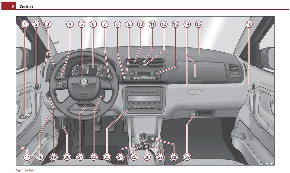
10 Cockpit 9 Cockpit General view This overview will help you to quickly familiarise yourself with the displays and the control elements. A1 A2 A3 A4 A5 A6 A7 A8 A9 A10 A11 A12 A13 A14 A15 A16 A17 A18 Power windows Electric exterior mirror adjustment Air outlet vents Lever for the multi-functional switch: Turn signal light, headlight and parking light, headlight flasher Speed regulating system Steering wheel: with horn with driver airbag with controls for radio, radio navigation system and phone... Instrument cluster: Instruments and indicator lights Lever for the multi-functional switch: Multi-functional indicator Windshield wiper and wash system Switch for rear window heater TCS switch Air outlet vents Switch for hazard warning lights Indicator light for a switched off front seat passenger airbag.... Depending on equipment fitted: Operating controls for the heating Operating controls for the air conditioning system Operating controls for Climatronic Storage compartments on the front passenger side Front passenger airbag Switch passenger airbag deactivation Switch depending on equipment fitted: Release for luggage compartment door Interior monitor Fuse box in the dash panel A19 A20 A21 A22 A23 A24 A25 A26 A27 A28 A29 Light switch and headlamp beam adjustment Release lever engine compartment lid Lever for adjusting the steering wheel Ignition lock Depending on equipment fitted: Radio Radio navigation system Rocker switch for the heating on the driver's seat Central locking switch Depending on equipment fitted: Gearshift lever (manual gearbox) Selector lever (automatic gearbox) Rocker switch for the heating on the driver's seat Depending on equipment fitted: Ashtrays Storage compartment MDI , Cars with factory-fitted radio or navigation system are supplied with separate instructions for operating such equipment. The arrangement of the controls and switches and the location of some items on right-hand drive models may differ from that shown in page 8, fig. 1. The symbols on the controls and switches are the same as for left-hand drive models. Using the system Safety Driving Tips General Maintenance Breakdown assistance Technical data

11 10 Quick Reference Guide Quick Reference Guide Basic functions and important information Setting steering wheel position Introduction The chapter of the brief instruction is used as a quick reference of the most important operating elements of the vehicle. It is necessary to observe all the information which is contained in the following chapters of the Owner's Manual. Unlocking and locking car Fig. 3 Adjustable steering wheel: Lever on the steering column/the correct distance of the driver from the steering wheel Fig. 2 Remote control key A1 Unlocking the vehicle A2 Unlocking the boot lid A3 Locking the vehicle A4 Folding out/folding up of the key Further information page 39, Unlocking and locking the vehicle. You can set the height and the forward/back position of the steering wheel to the desired position. Pull the lever below the steering wheel down fig. 3 - left. Set the steering wheel to the desired position (concerning height and forward/back position). Push the lever upwards as far as the stop. You can set the height and the forward/back position of the steering wheel to the desired position. Further information page 86, Setting steering wheel position. Adjust the steering wheel so that the distance between the steering wheel and your chest is at least 25 cm fig. 3 - right. Not maintaining this minimum distance will mean that the airbag system will not be able to properly protect you - hazard! You must not adjust the steering wheel when the vehicle is moving! For safety reasons the lever must always be firmly pushed up to avoid the steering wheel altering its position unintentionally when driving - risk of accident!

12 Quick Reference Guide 11 Seat belt height adjuster A1 Adjusting a seat in a forward/back direction A2 Adjusting height of seat A3 Adjust the angle of the seat backrest Further information page 56, Adjusting the front seats - Variant 1 and page 57, Adjusting the front seats - Variant 2. Only adjust the driver seat when the vehicle is stationary - risk of injury! Fig. 4 Front seat: Seat belt height adjuster Electric exterior mirror adjustment To adjust the belt height press the height adjuster and move it up or down fig. 4. Then pull firmly on the belt to ensure that the seat belt height adjuster has correctly locked in place. Further information page 115, Seat belt height adjuster on the front seats. Adjust the height of the belt in such a way that the shoulder part of the belt is positioned approximately across the middle of your shoulder - on no account across your neck! Adjusting the front seats Fig. 6 Inner part of door: Rotary knob Heating of the external mirror Adjusting the left-hand exterior mirror Adjusting the right-hand exterior mirror Switching off operating control Further information page 55. Fig. 5 Controls at seat: Version 1/version 2 Using the system Safety Driving Tips General Maintenance Breakdown assistance Technical data

13 12 Quick Reference Guide Switching lights on and off A Turn signal light right AB Turn signal light left AC Switching over between low beam and main beam lights AD Headlight flasher Further information page 49, The turn signal and main beam lever. Windscreen wiper lever Fig. 7 Dash panel: Light switch Switching off all lights Switching on side lights Switching on the low beam and main beam Fig. 9 Windscreen wiper lever Fog lights A Intermittent switch Rear fog light A0 A1 Wipers off Intermittent wipe Further information page 45, Switching lights on and off. A2 A3 Slow wipe Fast wipe Turn signal and main beam lever A4 A5 one time wipe Automatic wipe/wash Rear window wiper A6 Intermittent wipe - every 6 seconds A7 Automatic wipe/wash Further information page 52, Windshield wiper. Fig. 8 Turn signal and main beam lever

14 Quick Reference Guide 13 Power windows Fig. 10 Buttons on the driver's door A Button for the power window in the driver's door AB Button for the power window in the front passenger's door AC Button for the power window at the rear right door AD Button for the power window at the rear left door AS Safety switch Further information page 41, Buttons for electrical power windows. Hold the fuel tank cap of the fuel filler tube with one hand and unlock it by turning with the vehicle key to the left. Unscrew the fuel filler cap anti-clockwise and place the fuel filler cap from above on the fuel filler flap fig right. Closing fuel filler cap Screw on the cap by turning it to the right until it is heard to lock. Hold the fuel filler cap on the fuel filler tube with one hand and lock it by turning the vehicle key to the right and withdraw the key. Press the fuel tank flap closed. Further information page 156, Refuelling. Bonnet remote release Refuelling Fig. 12 Release lever engine compartment lid Pull the unlocking lever below the dash panel on the left-hand side fig. 12. Further information page 158, Bonnet remote release. Fig. 11 Right rear side of the vehicle: Fuel filler flap/fuel filler flap with cap unscrewed Opening the fuel filler cap Open the fuel filler flap with the hand fig left. Using the system Safety Driving Tips General Maintenance Breakdown assistance Technical data

15 14 Quick Reference Guide Opening the bonnet Fig. 13 Radiator grille: Locking lever/securing the bonnet with the bonnet support Pull on the locking lever fig left, the bonnet is then unlocked. Take the bonnet support out of its holder and set it in the opening designed for it fig right. Further information page 158, Opening and closing the bonnet.. Inspecting the engine oil level Fig. 14 Dipstick Aa Engine oil must not be refilled. Ab Engine oil can be refilled. Ac Engine oil must be refilled. Further information page 160, Check engine oil level.

16 Instruments and warning lights 15 Instruments and warning lights Overview of the instrument cluster Fig. 15 Instrument cluster A1 A2 A3 A4 A5 Engine revolutions counter page 15 Display with counter for distance driven page 16 with Service Interval Display page 17 with digital clock page 18 with Multi-functional display page 18 with Information display page 22 Speedometer page 16 Coolant temperature gauge page 16 Button for display mode: Set hours/minutes Activating/deactivating the second speed in mph or km/h Service interval - Display of the remaining number of days, kilometres or miles to the next Inspection Service / Reset 1) 1) Valid for countries where the values are indicated in British measuring units. A6 A7 Button for: Reset trip counter for distance driven Resetting Service Interval Display Set hours/minutes Activate/deactivate display mode Fuel gauge page 16 Engine revolutions counter The red zone of the rev counter scale A1 fig. 15 indicates the range in which the engine control unit begins to limit the engine speed. The engine control unit restricts the engine speed to a steady limit value. Shift into the next higher gear or select the selector lever position D of the automatic gearbox before reaching the red zone of the rev counter scale. Avoid high engine speeds during the driving time and before the engine has been warmed up to operating temperature page 140. Using the system Safety Driving Tips General Maintenance Breakdown assistance Technical data
 1) Valid for countries where the values are indicated in")
17 16 Instruments and warning lights For the sake of the environment Shifting to a higher gear in good time helps to reduce the fuel consumption, minimises operating noise levels, protects the environment and contributes to a longer life and reliability of the engine. Speedometer Warning against excessive speeds An acoustic warning signal will sound when the vehicle speed exceeds 120 kilometres per hour. The acoustic warning signal will switch off again when the vehicle speed goes below this speed limit. Coolant temperature gauge The coolant temperature gauge A4 page 15, fig. 15 operates only when the ignition is switched on. In order to avoid any damage to the engine, please follow the following notes regarding the temperature ranges: Cold range If the pointer is in the left-hand area of the scale it means that the engine has not yet reached its operating temperature. Avoid running at high engine speeds, at full throttle and at severe engine loads. The operating range The engine has reached its operating temperature as soon as the pointer moves into the mid-range of the scale. The pointer may also move further to the right at high engine loads and high outside temperatures. This is not critical provided the warning symbol in the instrument cluster does not flash. If the symbol in the instrument cluster flashes it means that either the coolant temperature is too high or the coolant level is too low. Please refer to the following guidelines page 28, Coolant temperature/coolant quantity. Pay attention to the warning notes page 158, Working in the engine compartment before opening the bonnet and inspecting the coolant level. Caution Additional headlights and other attached components in front of the fresh air inlet impair the cooling efficiency of the coolant. There is then a risk of the engine overheating at high outside temperatures and high engine loads! Fuel gauge The fuel gauge A7 page 15, fig. 15 only operates when the ignition is switched on. The fuel tank has a capacity of about 45 litres. The warning symbol in the instrument cluster lights up when the pointer reaches the reserve marking. There are now about 7 litres of fuel remaining in the tank. This symbol is a reminder for you, that you must refuel. The following is displayed in the information display: Please refuel. An audible signal sounds as an additional warning signal. On some vehicles, the fuel gauge is shown in the display of the instrument cluster. Caution Never run the fuel tank completely empty! An irregular supply of fuel can lead to irregular engine running. Unburnt fuel may get into the exhaust system and damage the catalytic converter. Counter for distance driven The counter for the distance driven is located in the bottom area of the display. The distance which you have driven with your vehicle is shown in kilometres (km). In some countries the measuring unit mile is used. Reset button If you hold the reset button A6 page 15, fig. 15 pressed for about 1 second, the trip counter is set back to zero. Trip counter for distance driven The trip counter indicates the distance which you have driven since this counter was last reset - in steps of 100 metres or 1/10 of a mile.

18 Instruments and warning lights 17 Counter for distance driven The counter for distance driven indicates the total distance in kilometers or miles which the vehicle has been driven. Fault display If there is a fault in the instrument cluster Error will appear as a permanent text in the display. Have the fault rectified as soon as possible by a specialist workshop. Never seek to adjust the trip counter for distance driven while driving for safety reasons! If vehicles which are fitted with the information display the display of the second speed is activated in mph or km/h, this driving speed is indicated instead of the counter for the total distance driven. Service Reminder Fig. 16 Service Interval Display: Depending on the equipment installed in the vehicle, the text can differ on the display. Service Interval Display Before the next service interval a key symbol and the remaining kilometres are indicated after switching on the ignition fig. 16. At the same time, a display appears regarding the remaining days until the next service interval. The following is displayed in the information display: Service in... km or... days. The kilometre indicator or the days indicator reduces in steps of 100 km. or days until the service due date is reached. A flashing key symbol appears in the display for 20 seconds as soon as the due date for the service is reached, as well as the following text Service. The following is displayed in the information display: Service now! Display regarding the distance and days until the following service interval You can use the button A5 to display the remaining distance driven and the days until the next service interval page 15. A key symbol and a display regarding the remaining kilometers appear for 10 second in the display. At the same time, a display appears regarding the remaining days until the next service interval. In vehicles with an information display, call this display in the Settings page 24 menu. The following will be displayed in the information display for 10 seconds: Service in... km or... days. Resetting Service Interval Display It is only possible to reset the Service Interval Display, if a service message or at least a pre-warning is shown on the display of the instrument cluster. We recommend having this resetting performed by a specialist garage. The specialist garage: resets the memory of the display after the appropriate inspection; makes an entry in the Service Schedule; affix the sticker with the entry of the following service interval to the side of the dash panel on the driver's side. Reset the service interval displays by using the reset button A6 page 15 on the trip counter. In vehicles with an information display, call this display in the Settings page 24 menu. Using the system Safety Driving Tips General Maintenance Breakdown assistance Technical data

19 18 Instruments and warning lights Caution We recommend that you do not reset the Service Interval Display yourself otherwise this can result in the service interval display being incorrectly set, which may also result in problems with operation of your vehicle. Never reset the display between service intervals otherwise this may result in incorrect readouts. information is retained in the Service Interval Display also after the battery of the vehicle is disconnected. If the instrument cluster is exchanged after a repair, the correct values must be entered in the counter for the Service Interval Display. This work is carried out by a specialist garage. After resetting the display with flexible service intervals (QG1), the data displayed are the same as for a car with fixed service intervals (QG2). We therefore recommend having the Service Interval Display reset only by an authorised Škoda Service Partner who is familiar with the procedure for resetting the display with a vehicle system tester. Please refer to the brochure Service schedule for extensive information about the service intervals. Digital clock The time is set with the buttons A5 and A6 page 15, fig. 15. Select the display which you wish to change with the button A5 and carry out the change with the button A6. In vehicles which are fitted out with the information display, it is possible to set the time in the menu Time page 24. The clock should not be adjusted while driving for safety reasons but only when the vehicle is stationary! Gearshift indicator for changing gears An information for the engaged gear A fig. 17 is shown in the display of the instrument cluster. In order to minimise the fuel consumption, a recommendation for shifting into another gear is indicated in the display. If the control unit recognises that it is appropriate to change the gear, an arrow AB is shown in the display. The arrow points up or down, depending on whether it is recommended to shift into a higher or lower gear. At the same time, the recommended gear is indicated instead of the currently engaged gear A. Multi-functional indicator (onboard computer) Introduction Fig. 17 Shift recommendation for changing gears The multi-functional indicator appears in the display page 19, fig. 18 or in the information display page 22 depending on the equipment fitted to your vehicle. The multi-functional indicator offers you a range of useful information. The outside temperature page 20 Driving time page 20 Current fuel consumption page 20 Average fuel consumption page 20

20 Instruments and warning lights 19 Range page 20 Distance driven page 21 Average speed page 21 Current speed page 21 oil temperature page 21 Warning against excessive speeds page 21 In vehicles which are fitted out with an information display, it is possible to switch off the display of some information. In certain national versions the displays appear in the Imperial system of measures. If the display of the second speed is activated in mph, the current speed is not indicated in km/h on the display. Memory Single-trip memory (memory 1) The single-trip memory collates the driving information from the moment the ignition is switched on until it is switched off. New data will also flow into the calculation of the current driving information if the trip is continued within 2 hours after switching off the ignition. If the trip is interrupted for more than 2 hours, the memory is automatically erased. Total-trip memory (memory 2) The total distance driven memory gathers data from any number of individual journeys up to a total of 19 hours and 59 minutes driving or kilometres driven. 99 hours and 59 minutes driving time or km distance driven in vehicles with an information display. The memory is deleted when either of these limits is reached and the calculation starts from anew. The total-trip memory will not, contrary to the single-trip memory, be deleted after a period of interruption of driving of 2 hours. All information in the memory 1 and 2 is erased if the battery of the vehicle is disconnected. Using the system Fig. 18 Multi-functional indicator The multi-functional indicator is equipped with two automatic memories. The selected memory is displayed in the middle of the display field fig. 18. The data of the single-trip memory (memory 1) is shown if a 1 appears in the display. A 2 shown in the display means that data relates to the total distance memory (memory 2). Switching over the memory takes place with the button AB fig. 19 on the windshield wiper lever. Fig. 19 Multi-functional indicator: Control elements The rocker switch A and the button AB are located on the windshield wiper lever fig. 19. Selecting the memory Short-term pressing of the button AB on the windshield wiper lever allows to select the desired memory. Using the system Safety Driving Tips General Maintenance Breakdown assistance Technical data
 The single-trip memory collates the driving information from the moment the ignition is switched on until it is switched off.")
21 20 Instruments and warning lights Selecting the functions Press the top or bottom rocker switch A for longer than 0.5 seconds. In this way, call up in sequence the individual functions of the multi-functional indicator. Setting function to zero Select the memory you want. Press button AB for more than 1 second. The following readouts of the selected memory will be set to zero by button AB : average fuel consumption; distance driven; average speed; Driving time. You can only operate the multi-functional indicator when the ignition is switched on. After the ignition is switched on, the function displayed is the one which you last selected before switching off the ignition. Outside temperature The outside temperature appears in the display when the ignition is switched on. If the outside temperature drops below +4 C, a snow flake symbol (warning signal for ice on the road) appears in front of the temperature indicator and flashes for 10 seconds, then remains displayed together with the outside temperature. At the same time an audible signal sounds. After pressing the rocker switch A on the windshield wiper lever page 19, fig. 19, the function which was shown last is indicated. Do not only rely upon the information given on the outside temperature display that there is no ice on the road. Please note that black ice may also be present on the road surface even at temperatures around +4 C - warning, drive with care! Driving time The driving time which has elapsed since the memory was last erased, appears in the display page 19. If you wish to calculate the driving time from a particular time of day you must first erase the memory at this moment in time by pressing the button AB page 19, fig. 19. The maximum distance indicated in both memories is 19 hours and 59 minutes. 99 hours and 59 minutes in vehicles with an information display. The indicator is set back to null if this period is exceeded. Current fuel consumption The current fuel consumption level is shown in the display in litres/100 km. This information can help you to adapt your style of driving to the fuel consumption you wish to achieve. The display appears in litres/hour if the vehicle is stationary or driving at a low speed. The indicated value will be updated every 0,5 seconds while you are driving. Average fuel consumption The average fuel consumption since the memory was last erased is shown in the display in litres/100 km page 19. This information can help you to adapt your style of driving to the fuel consumption you wish to achieve. If you wish to determine the average fuel consumption over a certain period of time, you must erase the memory at the start of the new measurement using the button AB on the windshield wiper lever page 19, fig. 19. A zero appears in the display for approx. the first 300 m you drive after erasing the memory. The indicated value will be updated every 5 seconds while you are driving. The amount of fuel consumed will not be indicated. Range The estimated range in kilometres is shown on the display. It indicates the distance you can still drive with your vehicle based on the present level of fuel in the tank for the same style of driving.
22 Instruments and warning lights 21 The readout is shown in steps of 10 km. After lighting up of the indicator light for the fuel reserve the display is shown in steps of 5 km. The fuel consumption for the last 50 km is taken as a basis for calculating the range. If you drive in a more economical manner from this moment on, the range will be increased accordingly. If the memory is set to zero (after disconnecting the battery), the fuel consumption of 10 ltr./100 km is calculated for the range; afterwards the value is adapted accordingly to the style of driving. Distance driven The distance driven since the memory was last erased appears in the display page 19. If you wish to calculate the distance driven as of a particular time, you must erase the memory at this moment in time by pressing the button AB on the windshield wiper lever page 19, fig. 19. The maximum distance indicated in both memories is km or in vehicles with information display, it is km. The indicator is set back to null if this period is exceeded. Average speed The average speed since the memory was last erased is shown in the display in km/hour page 19. If you wish to determine the average speed over a certain period of time, you must erase the memory at the start of the new measurement by pressing the button AB on the windshield wiper lever page 19, fig. 19. A zero appears in the display for the first 100 m you drive after erasing the memory. The indicated value will be updated every 5 seconds while you are driving. Current speed The current speed which is identical to the display of the speedometer, is indicated on the display A3 page 15, fig. 15. oil temperature If the oil temperature is lower than 50 C or if a fault in the system for checking the oil temperature is present, three lines are displayed instead of the oil temperature. Warning against excessive speeds This function enables you to set a speed limit and will notify you when this speed limit is exceeded. Set the speed limit when the vehicle is stationary With switch A page 19, fig. 19, choose the menu point Warning against excessive speeds. Press the button AB to active the ability to set the speed limit (value flashes). Use the button A to adjust the required speed limit, e.g. to 50 km/h. Confirm the speed limit that was set with button AB, or wait approx. 5 seconds until the setting is saved automatically (the value stops flashing). This is how you can set the speed limit in 5 km/h intervals. Set the speed limit when the vehicle is moving With switch A, choose the menu point Warning against excessive speeds. You can drive at the desired speed, e.g. 50 km/h. Press button AB to accept the current speed as the speed limit (the value flashes). If you wish to change the speed limit that was set, it is changed in 5 km/h intervals (e.g. the accepted speed of 47 km/h increases to 50 km/h or decreases to 45 km/h). Confirm the speed limit that was set by pressing button AB again, or wait approx. 5 seconds until the setting is saved automatically (the value stops flashing). Changing or removing the speed limit With switch A, choose the menu point Warning against excessive speeds. Remove the speed limit with button AB. Pressing the button AB again activates the change mode for the speed limit. If you go faster than the speed limit that was set, you will be notified with an acoustic warning. A Warning against excessive speeds appears together with the set limit on the display. The set speed limit remains stored even after switching off the ignition. Using the system Safety Driving Tips General Maintenance Breakdown assistance Technical data
23 22 Instruments and warning lights Pay attention primarily to the traffic situation! As the driver you are fully responsible for road safety. Main menu MAXI DOT display (information display) Introduction The information display provides you with information in a convenient way concerning the current operating state of your vehicle. The information system also provides you with data (depending on the equipment installed in the vehicle) relating to the radio, mobile phone, multi-functional indicator, radio navigation system, the unit connected to the MDI input and the automatic gearbox. Certain functions and operating conditions are always being checked on the vehicle when the ignition is switched on and also while driving. Functional faults, if required repair work and other information are indicated by red symbols page 23 and yellow symbols page 23. Lighting up of certain symbols is combined with an acoustic warning signal. Information and texts giving warnings are also shown in the display page 25. The following information can be shown in the display (depending on the equipment installed on the vehicle): Main menu page 22 Door, luggage compartment door and bonnet ajar warning page 23 Service Interval Display page 17 Selector lever position for an automatic gearbox page 96 You can activate the Main menu by pressing the rocker switch A fig. 20 for more than 1 second. You can select individual menu points by means of the rocker switch A. When the pushbutton AB is briefly pressed, the information you have selected is displayed. You can select the following information (depending on the equipment installed on the vehicle): MFD page 18 Audio Navigation Phone page 102 Fig. 20 Information display: Control elements Vehicle status page 23 Settings page 24 The menu point Audio is only then displayed when the factory-fitted car radio is switched on. The menu point Navigation is only then displayed when the factory-fitted radio navigation system is switched on. If warning messages are shown in the information display page 23, these messages can be confirmed with the button AB on the windshield wiper lever in order to call up the main menu.
24 Instruments and warning lights 23 If you do not activate the information display at that moment, the menu shifts to one level higher every 10 seconds. The operation of the factory-fitted radio or the navigation system is described in separate operating instructions to be found in the on-board literature. Door, luggage compartment door and bonnet ajar warning The door, luggage compartment and bonnet ajar warning lights up if at least one door, the luggage compartment or bonnet are not closed. The symbol indicates which door is still open or whether the luggage compartment door or bonnet is not closed. The symbol goes out as soon as the doors, luggage compartment door and bonnet are completely closed. A warning signal sounds if the car is driven at a speed of more than 6km/hour and if the engine or the luggage compartment door is open. Auto Check Control Car state The Auto Check Control carries out a check of certain functions and vehicle components. The check is performed constantly when the ignition is switched on, both when the vehicle is stationary, as well as when driving. Some operational faults, urgent repairs, service work or other information appear in the display of the instrument cluster. The displays are shown with a red or yellow light symbol depending on the priority of the message. The red symbols indicate danger (priority 1) while the yellow symbols indicate a warning (priortity 2). Information for the driver may also appear in addition to the symbols page 25. There is at least one error message when the term Vehicle status is displayed in the menu. After selecting this menu the first of the error messages is displayed. Several error messages are shown on the display under the message e.g. 1/3. This indicates that the first of a total of three error messages is displayed. The respective messages are displayed one after the other in an interval of 5 seconds. Check as soon as possible the displayed error messages. As long as the operational faults are not rectified, the symbols are always indicated again. After the first display, the symbols are indicated without information for the driver. If a fault occurs, a warning signal will also sound in addition to the symbol and text in the display: Priority 1 - three warning signals Priority 2 - one warning signal Red symbols A red symbol signals danger. Bring the vehicle to a stop. Switch the engine off. Investigate the function indicated. Obtain professional assistance. Meaning of the red symbols: Engine oil pressure too low page 28 Three successive warning signals will sound if a red symbol appears. Yellow symbols A yellow symbol signals a warning. Check the relevant function as soon as possible. The meaning of the yellow symbols: Overheated clutches of the automatic gearbox DSG Check engine oil level, engine oil sensor faulty page 95 page 28 One warning signal will sound if a yellow symbol appears. If several operational faults of priority 2 exist, the symbols appear one after the other and are each illuminated for about 5 seconds. Using the system Safety Driving Tips General Maintenance Breakdown assistance Technical data
25 24 Instruments and warning lights Set-up You can change certain settings by means of the information display. The current setting is shown on the information display in the respective menu at the top below the line. You can select the following information (depending on the equipment installed on the vehicle): Language MFD Data Time Winter tyres Units Alternative speed displayed Service Interval Factory Setting Back After selecting the menu point Back you will reach one level higher in the menu. Second speed Here you can switch on the display of the second speed in mph or in km/h 2). Service Here you can have the kilometers still to be driven and the days until the following service interval shown and the Service Interval Display reset. Factory Setting After selecting the menu Factory setting the factory setting of the information display is restored. Language Here you can set in which language the warning and information texts should be displayed. Displays of the MFA Here you can switch off or on certain displays of the multi-functional indicator. Time Here you can set the time, the time format (12 or 24 hour indicator) and the time change summer/winter time. Winter tyres Here you can set at which speed a warning signal should sound. This function is used for e.g winter tyres with the permissible maximum speed less than the maximum speed of the vehicle. When exceeding the speed, the following is displayed on the information display: Snow tyres max. speed... km/h Measures Here you can set the units for temperature, consumption and distance driven. 2) Valid for countries where the values are indicated in British measuring units.
SIMPLY CLEVER. ŠKODA Fabia OWNER'S MANUAL
 SIMPLY CLEVER ŠKODA Fabia OWNER'S MANUAL Introduction You have opted for a ŠKODA our sincere thanks for your confidence in us. Your new ŠKODA offers you a vehicle featuring the most modern engineering
SIMPLY CLEVER. ŠKODA Yeti OWNER'S MANUAL
 SIMPLY CLEVER ŠKODA Yeti OWNER'S MANUAL Introduction You have opted for a ŠKODA our sincere thanks for your confidence in us. Your new ŠKODA offers you a vehicle featuring the most modern engineering
SIMPLY CLEVER. ŠKODA Octavia OWNER'S MANUAL
 SIMPLY CLEVER ŠKODA Octavia OWNER'S MANUAL Introduction You have opted for a ŠKODA our sincere thanks for your confidence in us. Your new ŠKODA offers you a vehicle featuring the most modern engineering
ŠkodaOctavia Tour OWNER S MANUAL SIMPLY CLEVER
 ŠkodaOctavia Tour OWNER S MANUAL SIMPLY CLEVER Introduction You have opted for a Škoda - our sincere thanks for your confidence in us. Your new Škoda offers you a vehicle featuring the most modern engineering
SIMPLY CLEVER. ŠKODA Citigo OWNER'S MANUAL
 SIMPLY CLEVER ŠKODA Citigo OWNER'S MANUAL Preface You have opted for a ŠKODA our sincere thanks for your confidence in us. Your new ŠKODA offers you a vehicle featuring the most modern engineering and
ŠkodaOctavia OWNER S MANUAL SIMPLY CLEVER
 ŠkodaOctavia OWNER S MANUAL SIMPLY CLEVER Introduction You have opted for a Škoda - our sincere thanks for your confidence in us. Your new Škoda offers you a vehicle featuring the most modern engineering
SIMPLY CLEVER. ŠKODA Octavia Owner's Manual
 SIMPLY CLEVER ŠKODA Octavia Owner's Manual Preface You have opted for a ŠKODA our sincere thanks for your confidence in us. Your new ŠKODA offers you a vehicle featuring the most modern engineering and
SIMPLY CLEVER. ŠKODA Fabia Owner's Manual
 SIMPLY CLEVER ŠKODA Fabia Owner's Manual Preface You have opted for a ŠKODA our sincere thanks for your confidence in us. Your new ŠKODA offers you a vehicle featuring the most modern engineering and a
ŠkodaFabia ŠkodaRoomster SUPPLEMENT TO THE OWNER'S MANUAL
 ŠkodaFabia ŠkodaRoomster SUPPLEMENT TO THE OWNER'S MANUAL Technical Changes 11/2010 SIMPLY CLEVER Introduction 1 Introduction This supplement to the FABIA Owner's manual Edition 05.10 and the ROOMSTER
Audi A3 Audi A3 Sportback Quick reference guide
 Audi A Audi A Sportback Quick reference guide Dear Audi Driver, This quick reference guide gives you a brief introduction to the main features and controls of your vehicle. However, it cannot replace the
2009 QUICK REFERENCE GUIDE GET INFORMED. ROLL.
 xb 2009 QUICK REFERENCE GUIDE GET INFORMED. ROLL. 2009 Scion xb This Quick Reference Guide is a summary of basic vehicle operations. It contains brief descriptions of fundamental operations so you can
Scion xb. Pocket Reference Guide. <http://www.scion.com/>, Contact
 EMAIL US , Contact 2006 CHAT On weekdays you can chat with a Scion Customer Advocate. , Have a Question? or Contact CALL US For the Scion Customer Experience
Table of Contents. Introducing AYGO. Accessing your vehicle 2 3. Lights 9. Wipers 10. Electric windows 4. Gear change 11
 AYGO Brief Guide Table of Contents Accessing your vehicle 2 3 Electric windows 4 Steering wheel (Vehicles with an adjustable type) 4 Seat and seat belt adjustment 5 Instrument Panel overview 6 Instrument
ŠkodaOctavia SUPPLEMENT TO THE OWNER'S MANUAL
 SIMPLY CLEVER ŠkodaOctavia SUPPLEMENT TO THE OWNER'S MANUAL Technical Changes 11/2009 Introduction 1 Introduction Electronic stability programme (ESP)* This supplement replaces the Owner's manual Edition
ŠkodaOctavia SUPPLEMENT TO THE OWNER'S MANUAL
 SIMPLY CLEVER ŠkodaOctavia SUPPLEMENT TO THE OWNER'S MANUAL Technical Changes 11/2010 Introduction 1 Introduction Seat heaters* This supplement replaces the Owner's manual OCTAVIA Edition 05.10 referred
SIMPLY CLEVER. ŠKODA Citigo Owner's Manual
 SIMPLY CLEVER ŠKODA Citigo Owner's Manual Layout of this Owner's Manual (explanations) This Owner's Manual has been systematically designed to make it easy for you to search for and obtain the information
QUICK GUIDE WEB EDITION WELCOME TO YOUR NEW VOLVO! VOLVO C30
 VOLVO C30 QUICK GUIDE WEB EDITION WELCOME TO YOUR NEW VOLVO! Getting to know your new car is an exciting experience. Look through this Quick Guide in order to quickly and easily learn some of the most
xd 2010 QUICK REFERENCE GUIDE GET INFORMED. ROLL.
 xd 2010 QUICK REFERENCE GUIDE GET INFORMED. ROLL. 2010 Scion xd This Quick Reference Guide is a summary of basic vehicle operations. It contains brief descriptions of fundamental operations so you can
Multi-information Display (see MID )
") Driving Position Memory (see Seats ) Power Mirrors (see Mirrors ) Indicators/Gauges (see Instrument Panel ) Multi-information Display (see MID ) HomeLink (see HomeLink ) Navigation System (see Navigation
Driving Position Memory (see Seats ) Power Mirrors (see Mirrors ) Indicators/Gauges (see Instrument Panel ) Multi-information Display (see MID ) HomeLink (see HomeLink ) Navigation System (see Navigation
How you can contribute to a cleaner environment
 How you can contribute to a cleaner environment The fuel consumption of your Škoda - and thus the level of pollutants contained in the exhaust - is also determined by how you drive. The noise level and
ŠkodaOctavia Supplement - for vehicles with LPG drive
 SIMPLY CLEVER ŠkodaOctavia Supplement - for vehicles with LPG drive 01/2011 Supplement - for vehicles with LPG drive (natural gas) 1 Supplement - for vehicles with LPG drive (natural gas) This supplement
2015 Scion tc Quick Reference Guide
 2015 Scion tc Quick Reference Guide 2015 Scion tc This Quick Reference Guide is a summary of basic vehicle operations. It contains brief descriptions of fundamental operations so you can locate and use
Owner s Manual. Operation, Safety and Maintenance TS 1515-A-08 MOVANO. Copyright by Vauxhall Motors Ltd., England.
 Owner s Manual MOVANO Operation, Safety and Maintenance Reproduction or translation, in whole or in par ts, is not permitted without prior written consent from Vauxhall Motors Ltd. All rights as understood
4008 FEATURES AND SPECIFICATIONS
 ACTIVE BODYSTYLE 5 door compact SUV SAFETY Driver and front passenger airbags Front side airbags Full length curtain airbags Driver knee airbag ABS with Electronic Brake Force Distribution (EBFD) Emergency
Operating Instructions Display, graphic. Numeric language
 Operating Instructions Display, graphic Numeric language Contents Numeric language, general... 1 Numeric language, general... 1 Display control stalk... 1 Text strings... 1 Stop message... 2 Change language...
Workshop Repair Manual
 Workshop Repair Manual N.T. 2863A All types Basic manual: M.R. 302 - M.R. 307 - M.R. 311 - M.R. 312 M.R. 291 - M.R. 293 77 11 196 407 OCTOBER 1997 Edition Anglaise "The repair methods given by the manufacturer
2015 Scion xb Quick Reference Guide
 2015 Scion xb Quick Reference Guide 2015 Scion xb This Quick Reference Guide is a summary of basic vehicle operations. It contains brief descriptions of fundamental operations so you can locate and use
A name a commitment! These are the criteria which have characterized the development of dependable everyday cars up to the present time.
 A name a commitment! Automobile development has been a ŠKODA commitment since 1905. Even in those days, the trade press wrote enthusiastically above the Laurin & Klement Model A: Solidly built, dependable
Practical accident assistance
 Practical accident assistance A guideline for Mercedes-Benz customers Please note: Changes may have been made to the products since this brochure went to press (12/2009). This brochure has been compiled
Ell STEERING COLUMN CONTROLS STEERING COLUMN CONTROLS
 STEERING COLUMN CONTROLS Ignition Switch........ 2-1 LightinglTurn Signal Control Lever... 2-5 Windshield Wiper and Washer Lever... 2-6 Rear Window Wiper/Washer Switch (if equipped)... 2-8 Tilt Steering
STEERING COLUMN CONTROLS
 STEERING COLUMN CONTROLS Ignition Switch... 2-1 Lighting/Turn Signal Control Lever... 2-5 Windshield Wiper and Washer Lever... 2-6 Rear Window WiperlWasher Switch (if equipped)... 2-8 Tilt Steering Lock
INSTRUMENT PANEL. 1995 Volvo 850 DESCRIPTION & OPERATION. 1995-96 ACCESSORIES & EQUIPMENT Volvo Instrument Panels
 INSTRUMENT PANEL 1995 Volvo 850 1995-96 ACCESSORIES & EQUIPMENT Volvo Instrument Panels 850 WARNING: When working around steering column and before performing repairs, disconnect and shield battery ground
Transporter Fitting Locations No. 804 / 1
 Page 1 of 10 Transporter Fitting Locations No. 804 / 1 Pin connector assigment of selected connections Overview: 1 - Ignition/starter switch -D- On steering column Connector assigment chapter 2 - Onboard
2014 Scion xd Quick Reference Guide
 2014 Scion xd Quick Reference Guide 2014 INDEX Scion xd OVERVIEW Engine maintenance 7 This Quick Reference Guide is a summary of basic vehicle operations. It contains brief descriptions of fundamental
XC60. Quick GUIDE Web Edition
 XC60 Quick GUIDE Web Edition WELCOME TO THE GLOBAL FAMILY OF VOLVO OWNERS! This Quick Guide provides a brief overview of the most common features and functions in your Volvo. The Owner s Manual and the
Exterior features. Rear parking sensors. Personalisation kits. puncture repair kit. Guide-me-home lighting
 Exterior features Personalisation kits These self-adhesive decals form part of a range of kits, very different one from another, which allow you to create a unique and attractive exterior for your vehicle.
Vehicle electrics in Polo Model Year 2002
 Service. Self-Study Programme 265 Vehicle electrics in Polo Model Year 2002 265_061 The range of electrical systems in new vehicles is expanding increasingly as a result of the ever more effective safety
The rear lights with the traditional C-shaped illumination will catch your eye.
 SIMPLY CLEVER The New ŠKODA Octavia Combi The feeling of being amazed is as rare as it is joyful. To keep being surprised by things we don t have to change everything. Sometimes it s enough just to change
WHY CHOOSING GENUINE PARTS
 F I A T 5 0 0 L O W N E R H A N D B O O K WHY CHOOSING GENUINE PARTS We really know your car because we invented, designed and built it: we really know every single detail. At Fiat Service authorised workshops
the alarm B If the vehicle is out of range when the button is pressed, the most recently stored status information will be shown.
 REMOTE KEY WITH PCC* personal car communicator Locks the doors and trunk and arms the alarm A. PCC* 1 Green light: vehicle is locked. 2 Yellow light: vehicle is unlocked. 3 Red light: alarm has been triggered.
Wiring diagrams 14 1. Component key for wiring diagrams 1 to 29 Note: Not all the items listed will be fitted to all models
 Wiring diagrams 14 1 Component key for wiring diagrams 1 to 29 Note: Not all the items listed will be fitted to all models No Description 00200 Alternator with built-in regulator 00500 Battery 01001 Starter
Owner s Handbook Right hand drive diesel models
 Owner s Handbook Right hand drive diesel models At the time this publication went to print, the illustrations and information provided were representative of manufacture. While retaining the basic features
Quick GUIDE Web Edition
 S60 Quick GUIDE Web Edition WELCOME TO THE GLOBAL FAMILY OF VOLVO OWNERS! Getting to know your new vehicle is an exciting experience. This Quick Guide provides a brief overview of the most common features
2. READY TO SET OFF 18-42. 3. EASE OF USE and COMFORT 43-84 1. FAMILIARISATION 4-17 4. SAFETY 85-102. Contents
 WELCOME Please note the following point: the fitting of electrical equipment or accessories which are not recommended by PEUGEOT may result in a failure of your vehicle's electronic system. Please note
SECTION 1-5 OPERATION OF INSTRUMENTS AND CONTROLS 06.0.711. Lights, Wipers and Defogger
 OPERATION OF INSTRUMENTS AND CONTROLS Lights, Wipers and Defogger SECTION 1-5 Headlights and turn signals................................... 76 Emergency flashers..........................................
The Touareg Electrical System
 Service. Self-Study Programme 298 The Touareg Electrical System Design and Function Vehicles with off-road capability are no longer just utility vehicles for a limited group of people. At all levels in
Keys... 2-2 Master, submaster and valet key... 2-2 Key number... 2-2. Door locks... 2-3 Power door locking switches... 2-5
 Doors and locks Keys........................................................................... 2-2 Master, submaster and valet key..................................... 2-2 Key number...............................................................
Mercedes-Benz Vito. Specifications
 Mercedes-Benz Vito Specifications Mercedes-Benz Technical Data Panel Van Specification Body Style Rated output (kw @ rpm) Max torque (Nm @ rpm) Injection Fuel consumption 1 (litres/100km) Front axle load
SECTION 2 3 OPERATION OF INSTRUMENTS AND CONTROLS. Lights, Wipers and Defogger
 OPERATION OF INSTRUMENTS AND CONTROLS Lights, Wipers and Defogger SECTION 2 3 Headlights and turn signals................................... 92 Emergency flashers..........................................
The Crafter Electrical system
 Service Training Self-study Programme 370 Commercial Vehicles The Crafter Electrical system Design and function Innovations in automotive engineering are also taking place in the commercial vehicle segment.
ARTICLE BEGINNING * PLEASE READ THIS FIRST * MODEL IDENTIFICATION VIN LOCATION VIN CODE ID EXPLANATION
 Article Text ARTICLE BEGINNING 1993-96 MAINTENANCE Volkswagen Maintenance Information Golf III, GTI (1995-96), Jetta III Cabrio (1995-96) * PLEASE READ THIS FIRST * NOTE: For scheduled maintenance intervals
FORD FOCUS Owner's Manual
 FORD FOCUS Owner's Manual The information contained in this publication was correct at the time of going to print. In the interest of continuous development, we reserve the right to change specifications,
OPEL ASTRA. Owner's Manual
 OPEL ASTRA Owner's Manual Contents Introduction... 2 In brief... 6 Keys, doors and windows... 20 Seats, restraints... 47 Storage... 67 Instruments and controls... 86 Lighting... 117 Climate control...
New Caddy Panel Van. Commercial Vehicles
 New Commercial Vehicles Specifications Engine Cylinders 4 4 4 4 4 Capacity (cm 3 ) 1598 1968 1968 1968 1968 utput (kw @ r/min) 81 @ 5800 81 @ 4200 81 @ 4200 81 @ 4200 103 @ 4200 Torque (Nm @ r/min) 155
Polo Sedan Specifications. 75812-MY15 Polo Sedan Spec Leaflet 210x297 V3.indd 1
 Polo Sedan Specifications 75812-MY15 Polo Sedan Spec Leaflet 210x297 V3.indd 1 1.4 Trendline 1.4 Comfortline 1.6 Trendline Engine Cylinders 4 4 4 4 4 4 Capacity (cm 3 ) 1,398 1,398 1,598 1,598 1,598 1,598
OPEL CORSA UTILITY BASE
 OPEL CORSA UTILITY BASE Exterior features 1.4i 1.7DTi 1.8i Bumpers (front & rear) - black Chrome grill Mud flaps Dual manual remote side mirrors - black Lockable fuel cap Pick-up box protective mouldings
Exterior FAMILIARISATION
 5 Exterior FAMILIARISATION 1 Exterior 6 Key - Remote control Complete unlocking of the vehicle. Complete locking of the vehicle. Key : chapter identification : page identification Sliding side door 2a
VAUXHALL Insignia. Owner s Manual Model Year 2009.5 Edition: January 2009 TS 1674-B-09
 VAUXHALL Insignia VAUXHALL Insignia 0-1 Owner s Manual Model Year 2009.5 Edition: January 2009 TS 1674-B-09 Contents Introduction... 2 In brief... 6 Keys, doors and windows... 19 Seats, restraints... 39
Grand Prix 7Jx17 alloy 225/45 R17. Porto 7½Jx17 alloy 225/45 R17. Toronto 6½Jx16 alloy 205/55 R16. Sedona 6½Jx16 alloy 205/55 R16
 1.6 Guarantees Trunk sill protection, plastic X X X X X X X X X 3-year / 120 000 km warranty X X X X X X X X X Volkswagen AutoMotion Plan : 5yr / 60 000 km X X X X X X X X X 15 000 km service intervals
2017 Audi Maintenance Schedule - All Models
 2017 Audi Maintenance Schedule - All Models MY 2017 Maintenance Intervals - USA Service Intervals If you are not sure when you should bring your Audi in for service or which services are to be performed
FORD B-MAX Owner's Manual
 FORD B-MAX Owner's Manual The information contained in this publication was correct at the time of going to print. In the interest of continuous development, we reserve the right to change specifications,
OWNER S MANUAL. Permolock C3. Docking system for Power wheelchair in vehicle
 OWNER S MANUAL US Permolock C3 Docking system for Power wheelchair in vehicle How to contact Permobil Head Office of the Permobil group Permolock C3 Docking system for electric wheelchair in vehicle Produced
Adaptive cruise control (ACC)
") Adaptive cruise control (ACC) PRINCIPLE OF OPERATION The Adaptive Cruise Control (ACC) system is designed to assist the driver in maintaining a gap from the vehicle ahead, or maintaining a set road speed,
Adaptive cruise control (ACC) PRINCIPLE OF OPERATION The Adaptive Cruise Control (ACC) system is designed to assist the driver in maintaining a gap from the vehicle ahead, or maintaining a set road speed,
5 Mechanisms and accessories
 5 Mechanisms and accessories 51A SIDE OPENING ELEMENT MECHANISMS 52A NON-SIDE OPENING ELEMENT MECHANISMS 54A WINDOWS 55A EXTERIOR PROTECTION 56A EXTERIOR EQUIPMENT 57A INTERIOR EQUIPMENT X79 NOVEMBER 2009
Getting to Know Your 2004 VIBE
 Congratulations on your purchase of a Pontiac Vibe. Please read this information and your Owner Manual to ensure an outstanding ownership experience. Note that your vehicle may not include all features
Touareg Component Locations No. 802 / 1
 Touareg Component Locations No. 802 / 1 1 Fuses 1.1 Fuses 1.1.1 Overview of Fuses 1 - Fuses (SB) on fuse panel B on left instrument panel Location page 3 Fuse Arrangements, from November 2006 page 4 2
The new ŠKODA Octavia Price and Equipment Overview
 The new ŠKODA Octavia Price and Equipment Overview Octavia Sedan Engine Transmission Power Torque MLP # / Driveaway^ MLP # / Driveaway^ MLP # / Driveaway^ MLP # / Driveaway^ 103TSI 6-sp Manual 103kW@5000
Quick Guide WELCOME TO YOUR NEW VOLVO! VOLVO XC90 WEB EDITION
 VOLVO XC90 Quick Guide WEB EDITION WELCOME TO YOUR NEW VOLVO! Getting to know your car is an exciting experience. fter looking through this Quick Guide you'll like your new Volvo even more. You can find
using the Remote Touch unit and push knob to select. STEP 5 Select category and push knob to select. Scroll to specific customization setting.
 Lexus Personalized Settings Your vehicle includes a variety of electronic features that can be programmed to your preferences. Programming of these features is performed once at no charge by your Lexus
SIMPLY CLEVER ŠkodaOctavia Scout 4x4 PRESS RELEASE - MARCH 2011
 PRESS RELEASE - MARCH 2011 PHOTOGRAPHIC PORTFOLIO Scout 001 Scout 002 Scout 003 Scout 004 Scout Premium 005 Scout Premium 006 Scout Premium 007 Scout Premium 008 Scout Premium 009 Scout Premium 010 Scout
The Touran Electrical system
 Service. Self-study programme 307 The Touran Electrical system Design and function The networking technology, used until now only in luxury class vehicles, will be a feature in compact vans, such as the
CAR DAILY VEHICLE PRE CHECKS INFORMATION. Page 1 of 6
 Page 1 of 6 CAR DAILY VEHICLE PRE CHECKS INFORMATION There are approximately 2.5 million vehicles in national fleet in Ireland. As vehicles age they are subject to wear and tear and unless attended to
Headlight switch. The daytime running. lights) turn on.
 turn on.") Headlight switch The headlights can be operated manually or automatically. U.S.A. Canada The daytime running lights turn on The side marker, parking (vehicles with halogen headlights), daytime running
Headlight switch The headlights can be operated manually or automatically. U.S.A. Canada The daytime running lights turn on The side marker, parking (vehicles with halogen headlights), daytime running
G-100/200 Operation & Installation
 G-100/200 Operation & Installation 2 Contents 7 Installation 15 Getting Started 16 GPS Mode Setup 18 Wheel Sensor Mode Setup 20 Fuel Calibration 23 Basic Operation 24 Telemetery Screen 27 Entering a Distance
CLK Cabriolet Operator s Manual
 CLK Cabriolet Operator s Manual CLK 320 CLK 430 Our company and staff congratulate you on the purchase of your new Mercedes-Benz. Your selection of our product is a demonstration of your trust in our company
Introduction. In this Self-study Programme we will explain to you the design and function of the CAN data bus. SSP 186/01
 Introduction The requirements relating to driving safety, driving comfort, exhaust emissions and fuel economy are are becoming ever more stringent. This entails more intensive information exchange between
ŠkodaAuto CAR RADIO BEAT SIMPLY CLEVER
 ŠkodaAuto CAR RADIO BEAT SIMPLY CLEVER Contents 1 Contents Radio....................................... Radio - Overview............................. Important information........................ Anti-theft
CLK Cabriolet Operator s Manual CLK 320 CLK 430
 CLK Cabriolet Operator s Manual CLK 320 CLK 430 Our company and staff congratulate you on the purchase of your new Mercedes-Benz. Your selection of our product is a demonstration of your trust in our company
Subaru Reference. This reference contains the following information: connector pinouts. connector pinouts
 Subject: Source: 1993 2010 Impreza, WRX, and Sti and 2002 07 Outback Sport ABS wiring diagrams, harness routing, and connector locations and pinouts Subaru service manuals This reference contains the following
ELECTRICAL WIRING (R.H. DRIVE VEHICLES)
") C-1 ELECTRICAL WIRING (R.H. DRIVE VEHICLES) CONTENTS GENERAL.......................... 3 WIRING HARNESS CONFIGURATION DIAGRAMS......................... 4 ENGINE COMPARTMENT................ 4 DASH PANEL...........................
C-1 ELECTRICAL WIRING (R.H. DRIVE VEHICLES) CONTENTS GENERAL.......................... 3 WIRING HARNESS CONFIGURATION DIAGRAMS......................... 4 ENGINE COMPARTMENT................ 4 DASH PANEL...........................
A/C-HEATER SYSTEM - AUTOMATIC
 A/C-HEATER SYSTEM - AUTOMATIC 1995 Volvo 850 1995-96 Auto. A/C-Heater Systems Volvo 850 * PLEASE READ THIS FIRST * WARNING: To avoid injury from accidental air bag deployment, read and carefully follow
USER MANUAL OPERATION AND USE OF CAR WITH. Diego G3 / NEVO SEQUENTIAL GAS INJECTION SYSTEM
 USER MANUAL OPERATION AND USE OF CAR WITH Diego G3 / NEVO SEQUENTIAL GAS INJECTION SYSTEM Page 2 z 7 Table of contents 1. STARTING THE ENGINE... 3 2. CONTROL PANEL... 3 2.1 Indication of the current level
G PART NUMBER OF CONNECTORS
 A 1 A/C Ambient Temp. Sensor 90980 11070 Buckle SW RH (w/ Power Seat) A/C Condenser Fan Motor (1G FE) 90980 10928 B 9 Buckle SW RH (w/o Power Seat) 90980 11212 A 2 A/C Condenser Fan Motor (2JZ GE) 90980
Owner s Handbook. Manual del Propietario Manuel du Proprietaire Betriebsanleitung
 Owner s Handbook Manual del Propietario Manuel du Proprietaire Betriebsanleitung Name/Nom/Nombre VIN/NIV S C R Address/Adresse/Dirección DEALER/REVENDEUR/HÄNDLER/CONCESIONARIO Tel/Tél Date of delivery/date
Octavia (1U) 17-Dashboard up to 00 identification Octavia (1U) 17-Dashboard up to 00 07 - Coding Octavia (1U) 17-Dashboard up to 00 10 - Adaptation
 17-Dashboard up to 00 identification Octavia (1U) 17-Dashboard up to 00 07 - Coding Octavia (1U) 17-Dashboard up to 00 10 - Adaptation") Octavia (1U) 17-Dashboard up to 00 identification Octavia (1U) 17-Dashboard up to 00 07 - Coding Octavia (1U) 17-Dashboard up to 00 10 - Adaptation Octavia (1U) 17-Dashboard from 01 identification Octavia
Octavia (1U) 17-Dashboard up to 00 identification Octavia (1U) 17-Dashboard up to 00 07 - Coding Octavia (1U) 17-Dashboard up to 00 10 - Adaptation Octavia (1U) 17-Dashboard from 01 identification Octavia
TOYOTA ELECTRONIC TRANSMISSION CHECKS & DIAGNOSIS
 Checks and Adjustments The transmission requires regular maintenance intervals if it is to continue to operate without failure. As we discussed in previous sections, transmission fluid loses certain properties
FORD ECOSPORT Owner's Manual
 FORD ECOSPORT Owner's Manual The information contained in this publication was correct at the time of going to print. In the interest of continuous development, we reserve the right to change specifications,
INSTRUMENTS and CONTROLS
 INSTRUMENTS and CONTROLS PETROL - DIESEL MANUAL GEARBOX INSTRUMENT PANELS Screen 1 Panel grouping together the vehicle operation indication dials and warning lamps. Dials 1. Rev counter. Indicates the
Porsche Service. Cayenne (from MY 2008 for the following countries:
 Porsche Service Cayenne (from MY 2008 for the following countries: Abu Dhabi, Bahrain, Dubai, Jordan, Qatar, Kuwait, Lebanon, Oman, Saudi Arabia, Syria) Porsche Cayenne Maintaining driving pleasure No
MODIFICATION OF YOUR VEHICLE
 FOREWORD Your INFINITI represents a new way of thinking about car design. It integrates advanced engineering and superior craftsmanship with a simple, refined aesthetic sensitivity associated with traditional
ENGLISH OWNER HANDBOOK. Alfa Services
 Cop Alfa Giulietta GB:Alfa 159 cop. LUM GB 15-09-2011 15:08 Pagina 1 ENGLISH OWNER HANDBOOK Alfa Services WHY CHOOSING GENUINE PARTS We really know your car because we invented, designed and built it:
Viano 2012 Model Year Specification & Manufacturer s Recommended List Price. 29 August, 2012
 Viano 2012 Model Year Specification & Manufacturer s Recommended List Price 29 August, 2012 The Viano on-road IMAGE Model Technical data Transmission Fuel data Key Highlights Viano 3.0 CDI 2,987cc, 6-cylinder,
ŠKODA Fabia - Pricelist
 Price Incl. 19% VAT ŠKODA Fabia - Pricelist Engine versions Fabia Air Pollution Regulation Combined Consumption CO2 emissions Price Incl. 19% VAT Engine 1.2 HTP / 70Bhp Active EU5 5.5 l/100 km 128 g/km
VOLVO OWNERS MANUAL V50
 VOLVO OWNERS MANUAL V50 WEB EDITION 2006 Dear Volvo owner We hope you will enjoy many years of driving pleasure in your Volvo. The car has been designed for the safety and comfort of you and your passengers.
2006 Volkswagen Maintenance Schedule by Miles/Kilometers
 2.0 Liter Engine: Engine: Change engine oil and oil filter Engine: Check for leaks Service interval display: Reset (Where applicable) Exhaust system: Check for damage & leaks Battery: Check Door check
BODY ELECTRICAL TOYOTA ELECTRICAL WIRING DIAGRAM WORKBOOK. ASSIGNMENT Version 1.8 WORKSHEETS. http://www.autoshop101.com
 BODY ELECTRICAL ASSIGNMENT Version 1.8 WORKSHEETS TOYOTA ELECTRICAL WIRING DIAGRAM WORKBOOK http://www.autoshop101.com Developed by Kevin R. Sullivan All Rights Reserved TOYOTA Table of Contents Wiring
Interior - Lights and Switches
 Interior - Lights and Switches Стр. 1 из 3 96-1 Interior - Lights and Switches Footwell Lights Footwell lights: Left Footwell Light W9 Right Footwell Light W10 Note: The front foot well lights are located
Electronically Controlled Air Suspension (ECAS) for Trucks
 for Trucks") $2.50 Electronically Controlled Air Suspension (ECAS) for Trucks Maintenance Manual No. 36 Issued 7-99 ECAS System for 6 x 2 and 6 x 4 Vehicles with Rear Air Suspensions Service Notes Service Notes This
$2.50 Electronically Controlled Air Suspension (ECAS) for Trucks Maintenance Manual No. 36 Issued 7-99 ECAS System for 6 x 2 and 6 x 4 Vehicles with Rear Air Suspensions Service Notes Service Notes This
Electronic Manual Gearbox
 Service. Self-Study Programme 221 Electronic Manual Gearbox Design and Function Taking the Lupo as the basis, Volkswagen has developed the world's first 3 L car that will also go into volume production.
MULTIPLEXED BSI OPERATING PRINCIPLE FOR THE XSARA PICASSO AND XSARA CITROËN UK LTD 221 BATH ROAD SLOUGH SL1 4BA
 CITROËN TECHNICAL TRAINING MULTIPLEXED BSI OPERATING PRINCIPLE FOR THE XSARA PICASSO AND XSARA CITROËN UK LTD 221 BATH ROAD SLOUGH SL1 4BA DEALER PERSONNEL DEVELOPMENT AND TRAINING CITROËN UK LTD. Reproduction