Meritor Rear Axle Seals
|
|
|
- Jocelyn Cameron
- 7 years ago
- Views:
Transcription
1 System: Axles, Driven Bulletin #: 22-4 Date: March 9, 2005 Meritor Rear Axle Seals Accompanying this bulletin is information on the new Multiple Lip Seals used in the Meritor rear drive axles. Please utilize this information when replacing seals in the Meritor rear ends. The required tools for this procedure will be shipped as received. Keep in mind that the warranty coverage on these seals is 3 years or 350,000 miles, whichever occurs first. If you have any questions, feel free to contact me at Location # 24. Thank you, Walter Kirkland Jr. Tallahassee Maintenance Department Attachments: Attachment 1: Meritor Technical Bulletin # TP-0446 Attachment 2: Meritor Product Information Letter # 430 Attachment 3: Meritor General Parts Bulletin # GP-999 C:\Documents and Settings\Administrator\Local Settings\Temporary Internet Files\Content.IE5\O7VN6GL9\22-04[1].doc

2 TP-0446 Issued Technical Bulletin Installing a Multiple-Lip Seal (MLS) onto Meritor 14X/16X/18X Single and 14X/16X/18X/38X Tandem Drive Axles Does Not Apply to Meritor Front Drive Steer Axles, Transfer Cases or Other Drive Axles Not Listed in This Publication. TP-0446 Issued 1 Technical XX-05Bulletin Table A: Driver and Sleeve Part Numbers Axle Model and Position Seal Service Part Number Previous Seal Part Number Seal Drivers Sleeve Drivers 14X/16X/18X/38X Forward-Rear Unit Input (FUI) A1-1205X2728 A-1205R T1 2728T2 14X/16X Forward-Rear Unit Output (FUO) A1-1205Y2729 A-1205P T1 2729T2 14X Rear-Rear Unit Input (RUI) A1-1205Z2730 A-1205N T Not Required Sleeve is unitized 16X/18X Rear-Rear Unit Input (RUI) A1-1205A2731 A-1205Q T Not Required Sleeve is unitized Forward input and output seals must be serviced with the seal and sleeve. The service part number provides both when required. Check your application carefully before installing the multiple-lip seal. How to Obtain Additional Maintenance and Service Information Refer to technical bulletin TP-0531, Multiple-Lip Seal Installation, for instructions on CD. Also, refer to technical bulletin TP-0534; Maintenance Manual 5A, Single-Reduction Differential Carriers; Maintenance Manual 5E, Tandem Axle Forward Carriers and Single Axle Carriers, Including Double-Reduction Carriers; or Maintenance Manual 5L, Single-Reduction Forward Differential Carriers on Tandem and Tridem Axles. To obtain these publications, call ArvinMeritor s Customer Service Center at , or visit the Tech Library on our website at arvinmeritor.com. Special Tools There are six new installation drivers required for replacement of the multiple-lip axle yoke seals. Figure 1. A sleeve driver and seal driver for the forward-rear input A sleeve driver and seal driver for the forward-rear output Two model specific seal drivers for the rear-rear input To obtain these sleeves, seals and drivers, call ArvinMeritor s Commercial Vehicle Aftermarket at Figure 1 Important Information This technical bulletin provides the recommended procedure for installing Meritor multiple-lip seals (MLS) on Meritor 14X/16X/18X single and 14X/16X/18X/38X tandem drive axles. These instructions do not apply to front drive steer axles, transfer cases or other drive axles not listed in this publication. The new Meritor multiple-lip seals feature a separable sleeve installed onto the yokes at the tandem forward-rear input and forward-rear output positions. No sleeve is used on the rear-rear input. Figure T1 2729T2 2730T 2728T1 2728T2 2731T a Installation of the new seals requires a set of four seal drivers and two sleeve drivers. Refer to Table A for part numbers.
 A1-1205X2728 A-1205R2592 2728T1 2728T2 14X/16X Forward-Rear Unit Output (FUO) A1-1205Y2729 A-1205P2590 2729T1 2729T2 14X Rear-Rear Unit Input (RUI) A1-1205Z2730")
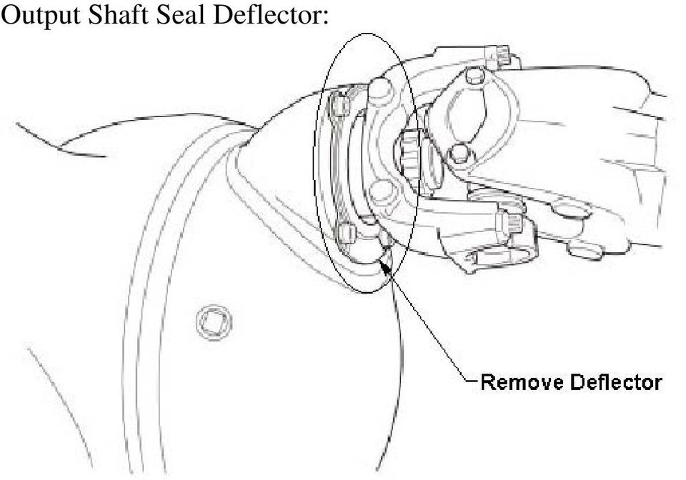
3 Removal WARNING To prevent serious eye injury, always wear safe eye protection when you perform vehicle maintenance or service. Park the vehicle on a level surface. Block the wheels to prevent the vehicle from moving. Support the vehicle with safety stands. Do not work under a vehicle supported only by jacks. Jacks can slip and fall over. Serious personal injury and damage to components can result. CAUTION On a rear-rear input, if you partially or fully install a yoke and then remove it for any reason, remove, discard and replace the seal with a new seal. If a seal or sleeve is removed after partial or full installation, discard the seal or sleeve and replace it with a new seal or sleeve. Damage to components can result. 1. Wear safe eye protection. 2. Park the vehicle on a level surface. Set the parking brake. Block the wheels to prevent the vehicle from moving. 3. Use a jack to raise the vehicle so that the wheels to be serviced are off the ground. Support the vehicle with safety stands. 4. Disconnect the drive shafts. 5. Attach a flange bar or place a yoke bar over the input or output yoke to hold the yoke or flange while you remove the nut. Always use a flange or yoke bar during removal and installation of the flange yoke nut to prevent damage to the gearing. Figure 2. Figure 2 WARNING Use a puller tool to remove the yoke or flange from the shaft. Do not use a hammer or mallet, which can damage components and cause vibration in the driveline. If this occurs, the driveline can separate from the vehicle during operation. Serious personal injury and damage to components can result. 6. Remove the yoke nut and washer. Use a puller tool to remove the yoke or flange from the shaft. Do not use a hammer or mallet, which can damage components. Figure 3. Figure 3 Figure 3 YOKE PULLER a CAUTION On axles that have the bolt-on deflector on the forward-rear output shaft bearing cage, the deflector must be removed and discarded. The new forward output sleeve will not assemble correctly to the new output seal with the bolt-on deflector in place. Remove the deflector from the output shaft bearing cage and reassemble the output cage hex-head capscrews and washers according to the appropriate maintenance manual instructions. Damage to components can result. 7. Carefully remove the pinion seal from the yoke or carrier. Do not damage the seal bore when you remove the seal. Do not allow dirt or grease to contaminate the seal bore or adjacent bearings. 8. If a seal sleeve is installed onto a yoke, remove the sleeve using a bearing puller. Do not reuse the seal sleeves. Figure 2 YOKE BAR b 9. Inspect the yoke seal area for damage that could cause lubricant leaks after you install the seal. Use emery paper or an equivalent product to remove scratches, nicks or burrs only. TP-0446 Issued (16579/24240) Page 2 Copyright ArvinMeritor, Inc., 2005 Printed in the USA

4 Installation WARNING Solvent cleaners can be flammable, poisonous and cause burns. Examples of solvent cleaners are carbon tetrachloride, and emulsion-type and petroleum-base cleaners. Read the manufacturer s instructions before using a solvent cleaner, then carefully follow the instructions. Also follow the procedures below. Wear safe eye protection. Wear clothing that protects your skin. Work in a well-ventilated area. Do not use gasoline, or solvents that contain gasoline. Gasoline can explode. You must use hot solution tanks or alkaline solutions correctly. Read the manufacturer s instructions before using hot solution tanks and alkaline solutions. Then carefully follow the instructions. 1. Clean the ground and polished surface of the yoke journal using a clean shop towel and a safe cleaning solvent. Do not use abrasive cleaners, towels or scrubbers to clean the yoke or flange surface. Do not use gasoline. 2. Inspect the yoke seal area for damage that could cause lubricant leaks after you install the seal. Use emery paper or an equivalent product to remove scratches, nicks or burrs only. 3. Install the deflector, if equipped, onto the yoke. You must install the deflector before you install the sleeve into the yoke. Figure 4. Figure 4 YOKE DEFLECTOR, IF EQUIPPED SLEEVE DRIVER a WARNING Observe all warnings and cautions provided by the press manufacturer to avoid damage to components and serious personal injury. Do not hit steel parts with a steel hammer. Pieces of a part can break off. Serious personal injury and damage to components can result. 4. Apply a light coat of axle oil to the yoke seal journal. Position the sleeve into the forward-rear axle output yoke sleeve driver. Do not touch the greased areas of the sleeve. The sleeve must be kept clean prior to assembly into the seal. Use an arbor press and the appropriate driver to install the sleeve into the yoke. Verify that the sleeve is fully-seated in the yoke to prevent damage to components. Figure 5. The yoke must be fully pressed into the sleeve driver until the end of the yoke bottoms out in the sleeve driver. This will correctly position the sleeve on the yoke. When correctly seated, the forward-rear output sleeve is positioned inch ± inch (5 mm ± 0.75 mm) from the end of the yoke. Figure 6. If you do not have a press: Position the yoke on a five-inch (127 mm) spacer on a workbench. Use a dead-blow hammer and the appropriate driver to install the sleeve into the yoke. Figure Apply a light coat of axle oil to the yoke seal journal. Position the sleeve into the forward-rear axle input yoke sleeve driver. Do not touch the greased areas of the sleeve. The sleeve must be kept clean prior to assembly into the seal. Use an arbor press and the appropriate driver to install the sleeve into the yoke. Verify that the sleeve is fully-seated in the yoke. Figure 8. The yoke must be fully pressed into the sleeve driver until the end of the yoke bottoms out in the sleeve driver. This will correctly position the sleeve on the yoke. When correctly seated, the forward-rear input sleeve is positioned inch ± inch (0.75 mm ± 0.75 mm) from the end of the yoke. Figure 6. If you do not have a press: Position the yoke on a five-inch (127 mm) spacer on a workbench. Use a dead-blow hammer and the appropriate driver to install the sleeve into the yoke. Figure 7. Figure 4 TP-0446 (16579/24240) Issued Printed in the USA Copyright ArvinMeritor, Inc., 2005 Page 3

5 Figure 5 Figure 8 FORWARD-REAR OUTPUT WITHOUT DEFLECTOR FORWARD-REAR INPUT WITH DEFLECTOR SLEEVE SLEEVE a a Figure 5 Figure 8 Figure 6 YOKE CAUTION Hold the sleeve and seal only on the outer diameter. Do not touch the greased inner diameter of the seal and the greased area of the sleeve. This can contaminate the seal and cause a leak between the shaft and the seal. Damage to components can result. SLEEVE End of the yoke must bottom out in the sleeve driver. DRIVER 6. Install the forward-rear axle input seal. Hold the sleeve and seal only on the outer diameter. Position the seal into the seal driver and align it with the forward-rear axle input bearing cage. Do not touch the lips in the inner diameter of the seal. Use a dead-blow hammer and the appropriate driver to install the seal into the bearing cage. Figure 9. FORWARD-REAR OUTPUT: 0.200" ± 0.030" (5 MM ± 0.75 MM) FORWARD-REAR INPUT: 0.030" ± 0.030" (0.75 MM ± 0.75 MM) Figure 9 FORWARD-REAR INPUT Figure a Figure a Figure 9 5" (127 MM) SPACER a Figure 7 TP-0446 Issued (16579/24240) Page 4 Copyright ArvinMeritor, Inc., 2005 Printed in the USA

6 CAUTION On axles that have the bolt-on deflector on the forward-rear output shaft bearing cage, the deflector must be removed and discarded. The new forward output sleeve will not assemble correctly to the new output seal with the bolt-on deflector in place. Remove the deflector from the output shaft bearing cage and reassemble the output cage hex-head capscrews and washers according to the appropriate maintenance manual instructions. Damage to components can result. Figure 11 REAR-REAR INPUT 7. Install the forward-rear axle output seal. Hold the sleeve and seal only on the outer diameter. Position the seal onto the seal driver and align it with the forward-rear axle output shaft. Do not touch the lips in the inner diameter of the seal. Use a dead-blow hammer and the appropriate driver to install the seal onto the output shaft. Figure 10. Figure 10 FORWARD-REAR OUTPUT Figure a 9. Use a feeler gauge to check the seal gap at all three axle positions. The seal is correctly installed if the gap is less than inch (0.127 mm) around the circumference of the seal flange. Figure 12. If the gap is more than inch (0.127 mm): Use a dead-blow hammer and the appropriate driver to completely install the seal. Figure a Figure Install the rear-rear axle input seal. Hold the seal only on the outer diameter. Position the seal into the seal driver and align it with the rear-rear axle input bearing cage. Use a dead-blow hammer and the appropriate driver to install the seal into the bearing cage. Figure 11. Figure a 10. Apply a light coat of axle oil to the yoke seal journal. Install the yokes and connect the drive shafts. Refer to the manuals specified in this bulletin for the correct procedures. TP-0446 (16579/24240) Issued Printed in the USA Copyright ArvinMeritor, Inc., 2005 Page 5

7 Meritor Heavy Vehicle Systems, LLC 2135 West Maple Road Troy, MI USA arvinmeritor.com Information contained in this publication was in effect at the time the publication was approved for printing and is subject to change without notice or liability. Meritor Heavy Vehicle Systems, LLC, reserves the right to revise the information presented or discontinue the production of parts described at any time. Copyright 2005 TP-0446 ArvinMeritor, Inc. Issued All Rights Reserved Printed in the USA (16579/24240)

8 PRODUCT INFORMATION LETTER ArvinMeritor, Inc West Maple Road Troy, MI PRODUCT INFORMATION LETTER #430 DATE: FEBRUARY 2005 SUBJECT: MULTIPLE LIP SEAL (MLS) MODELS: 14X/16X/18X SINGLE AND 14X/16X/18X/38X TANDEM DRIVE AXLES. Dear Customer, PRODUCT INFORMATION LETTER In the interest of continuous product improvement ArvinMeritor is pleased to announce the implementation of a newly designed multiple lip seal for our highest volume axle products. The new seal assembly, which is made using premium materials, improves oil containment, contaminant exclusion, while generally increasing seal effectiveness. The axle models affected include the RT-xx-14X, RT-xx-16X, RT-xx-18X and RT-xx-38X forward unit input (FUI) and the RT-xx-14X and RT-xx-16X forward unit output (FUO) seal positions. Also affected are the RT/RS-xx-14X, RT/RS-xx-16X and RT/RS-xx-18X rear unit input (RUI) seal positions. The FUI and FUO positions are soft unitized designs with two piece construction. These seals incorporate a seal sleeve, which is pre-installed on the yokes before yoke installation to the axle. The RUI seals are fully unitized with seal sleeves integral to the seal assembly. These new seals are an exclusive ArvinMeritor design to be used only with Meritor branded axles. The seals will be introduced into production as a running change beginning on March 7, PRODUCT INFORMATION LETTER Axle Model and Position MLS Part Number and Driver Information: Seal Service Part No. Previous Seal Part No. Seal Drivers Sleeve Drivers 14X/16X/18X/38X Forward-Rear Input (FUI) A1-1205X2728 A-1205R T1 2728T2 14X/16X Forward-Rear Output (FUO) 14X Rear-Rear Input (RUI) 16X/18X Rear-Rear Input (RUI) A1-1205Y2729 A-1205P T1 2729T2 A1-1205Z2730 A-1205N T1 Not Required Seal is unitized A1-1205A2731 A-1205Q T1 Not Required Seal is unitized PRODUCT INFORMATION LETTER

9 The new seals will require new seal and sleeve installation tools. For recommended installation instructions, please see Technical Bulletin TP ArvinMeritor recommends the use of specific seal and sleeve drivers to ensure proper positioning. A CD (TP-0531) has been developed which shows the correct methods used for seal installation and replacement. Replacement seals as well as seal and sleeve driver kits are available through ArvinMeritor Commercial Vehicle Aftermarket at The current bolt-on deflector (3264-J-1466) that is used on the RT-xx-14X and the RT-xx-16X forward unit output position is incompatible with the new seal design and will be discontinued with the implementation of the new seal. The seal sleeve that is assembled to the yoke also acts as a deflector with the new seal. If you have any questions, please contact your ArvinMeritor account representative. J. L. Malkowski J. L. Malkowski Director - Product Management CVS Axles

10 Fully Unitized one piece design: Seal with seal sleeve design soft unitized : Installation tools:

11 Forward Unit Input Seal Position: Forward Unit Output Seal Position: Rear Unit Input Seal Position:

12 Output Shaft Seal Deflector:
13 February 21, 2005 GP 999 GENERAL PARTS BULLETIN Subject: Meritor Multiple Lip Oil Seals (MLS) ArvinMeritor Commercial Vehicle Systems has issued Product Information Letter # 430 (see attached) announcing the release of a new pinion seal design for specific Meritor axles. This new seal is called the Meritor Multiple Lip Seal (MLS). The carriers affected include RT-xx-14X, RT-xx-16X, RT-xx-18X and RT-xx-38X forward unit input (FUI) and the RT-xx-14X and RT-xx-16X forward unit output (FUO) seal positions. Also affected are the RT/RS-xx-14X, RT/RS-xx16X and RT/RS-xx-18X rear unit input (RUI) seal positions. Certain applications (non-mls), such as transfer cases, front drive steer axles, cranes, lift truck and all AxleTech (off-highway) applications will continue to utilize the current seal design. Be sure to check your application before installing the new Meritor Multiple Lip Seal. Reference Technical Bulletin TP-0446 for installation instructions (see attached). ArvinMeritor Commercial Vehicle Aftermarket (CVA) has released four new service part numbers for the MLS seals, six new part numbers for the required installation tools, and a new KIT part number containing all six tools. Two of the new seals are a unitized one piece design and two are a two piece seal and sleeve design. DO NOT ATTEMPT TO INSTALL THE NEW SEALS OR SLEEVES WITHOUT THE NEW SEAL AND SLEEVE DRIVER TOOLS. CVA has also released four new part numbers to service non-mls applications. The vast majority of demand will be for the new MLS seals. Demand for non-mls applications should be less than 1% of that for MLS applications. Current seal driver tools will continue to be offered for non-mls applications.
 seal positions.")
14 Table 1: Multiple Lip Seal (MSL) part numbers ALL applications but those listed in table 2 below. Axle Model and Position Current Seal Design Part Number New Seal / Sleeve Service Part Number Seal Driver Tool Part Number Sleeve Driver Tool Part Number RT14X/16X/18X/38X Forward-Rear Input (FUI) A 1205R2592 A1 1205X2728 RT14X/16X Forward- Rear Output (FUO) A 1205P2590 A1 1205Y2729 RT/RS14X Rear-Rear Input (RUI) RT/RS16X/18X Rear- Rear Input (RUI) A 1205N2588 A 1205Q2591 A1 1205Z2730 A1 1205A T1 Included in KIT T1 Included in KIT T1 Included in KIT T1 Included in KIT T2 Included in KIT T2 Included in KIT4463 Not required One Piece Design Not required One Piece Design New and Remanufactured Carriers: All new and remanufactured carriers for the affected models will be shipped with the new MLS seal installed and the yoke sleeve attached loose. For non-mls applications, the seal must be replaced with the appropriate current design seal. Availability: As CVA inventory is depleted on the current seal part numbers, these will be superceded to the new MLS seal part numbers (Table 1). At that time, orders on hand will be switched to the new MLS part numbers.

Procedures and Intervals to Inspect the Wheel Ends and Tighten the Spindle Nuts on Meritor TL Series Trailer Axles with Unitized Wheel Ends
 Technical Bulletin Revised 1 Technical 02-11 Bulletin Revised 02-11 Procedures and Intervals to Inspect the Wheel Ends and Tighten the Spindle Nuts on Meritor TL Series Trailer Axles with Unitized Wheel
DiscPlus DX195 and DX225 Air Disc Brakes
 Revised 11-04 Technical Bulletin Revised 1 Technical 11-04 Bulletin DiscPlus DX195 and DX225 Air Disc Brakes Inspection, Installation and Diagnostics Air Disc Brake Inspection Intervals and Procedures
Planetary Drive Axles
 Issued 07-00 $2.50 Planetary Drive Axles Maintenance Manual 9H PRLC 124 W2H PRLC 144 W2H Models PRLC 124 W2H PRLC 144 W2H Service Notes Service This Notes maintenance manual describes the correct service
System Saver 318 Air Compressor for Mack E-Tech and ASET Engines
 Maintenance Manual 31 System Saver 318 Air Compressor for Mack E-Tech and ASET Engines Revised 08-05 NON-THROUGH DRIVE THROUGH DRIVE Service Notes About This Manual This manual provides service and repair
ARVINMERITOR UNITIZED FRONT WHEEL HUB INSPECTION AND MAINTENANCE
 SERVICE BULLETIN (Also applies to Mack Trucks Australia) NUMBER: SB-423-002 DATE: 8/23/02 MODEL: All with FF981 Front Axle ARVINMERITOR UNITIZED FRONT WHEEL HUB INSPECTION AND MAINTENANCE The ArvinMeritor
AXLE SHAFTS - FRONT. 1998 Pontiac Bonneville MODEL IDENTIFICATION DESCRIPTION & OPERATION TROUBLE SHOOTING REMOVAL & INSTALLATION
 AXLE SHAFTS - FRONT 1998 Pontiac Bonneville 1998-99 DRIVE AXLES FWD Axle Shafts - Cars - "C", "G" & "H" Bodies GM Aurora, Bonneville, Eighty Eight, LeSabre, LSS, Park Avenue, Regency, Riviera MODEL IDENTIFICATION
DO NOT attempt to repair hub and wheel bearing assembly.
 Page 1 of 6 HUB & WHEEL BEARINGS (WITH PULSE VACUUM HUBLOCK) DO NOT attempt to repair hub and wheel bearing assembly. Removal DO NOT remove hub lock assembly by prying on hub lock legs. This can crack
Meritor WABCO Hydraulic Power Brake (HPB) System Bleeding Procedures
 System Bleeding Procedures") Issued 03-10 Technical Bulletin Meritor WABCO Hydraulic Power Brake (HPB) System Bleeding Procedures Issued 1 Technical 03-10 Bulletin Hazard Alert Messages Read and observe all Warning and Caution hazard
Issued 03-10 Technical Bulletin Meritor WABCO Hydraulic Power Brake (HPB) System Bleeding Procedures Issued 1 Technical 03-10 Bulletin Hazard Alert Messages Read and observe all Warning and Caution hazard
Spicer Axles & Brakes ABIB-0302
 Information Bulletin Bulletin Type: Parts / Service Information Topic: Dana LMS Hub Assembly Procedure Steer and Drive Axles Spicer Axles & Brakes ABIB-0302 Note: Bulletin ABIB-0302 replaces the original
1.8 CRANKSHAFT OIL SEALS
 SERIES 60 SERVICE MANUAL 1.8 CRANKSHAFT OIL SEALS An oil seal is fitted between each end of the crankshaft and the bores of the flywheel housing and gear case cover to retain the lubricating oil in the
DANA 30 MANUAL HUB CONVERSION KIT
 DANA 30 MANUAL HUB CONVERSION KIT 12194 PLEASE READ AND UNDERSTAND ALL INSTRUCTIONS BEFORE YOU BEGIN Your safety and the safety of other motorists is very important. Your Jeep is an off road capable vehicle
INTRODUCTION KINGPIN REPLACEMENT
 KINGPIN REPLACEMENT Author: Randy Baumann All information, illustrations and specifications are based on the best information available at the time of publication. The author cannot guarantee the accuracy
ReadyLift (Part# 66-5075) Strut Extension, Installation Instructions Toyota Tundra New Body Style 2WD & 4WD
 Strut Extension, Installation Instructions Toyota Tundra New Body Style 2WD & 4WD") SAFETY WARNING: recommends this system be installed by a professional technician. In addition to these instructions, professional knowledge of disassembly/ reassembly procedures and post installation checks
SAFETY WARNING: recommends this system be installed by a professional technician. In addition to these instructions, professional knowledge of disassembly/ reassembly procedures and post installation checks
Slack Adjuster. Table of Contents
 Slack Adjuster Table of Contents Sub-Headings Safety 3 Warnings 3 s 3 s 3 Automatic Slack Adjuster Service 3 PayMaster Automatic Slack Adjuster 3 How the Automatic Slack Adjuster Works 3 Pressed-In, Sealed
Rebuild Instructions for 70001 and 70010 Transmission
 Rebuild Instructions for 70001 and 70010 Transmission Brinn, Incorporated 1615 Tech Drive Bay City, MI 48706 Telephone 989.686.8920 Fax 989.686.6520 www.brinninc.com Notice Read all instructions before
TECHNICAL BULLETIN. Meritor WABCO Cab Leveling Valves and Chassis Leveling Valves. How the Cab Leveling and Chassis Leveling Valves Work
 Revised 02-00 TECHNICAL BULLETIN Meritor WABCO Cab Leveling Valves and Chassis Leveling Valves This technical bulletin covers both cab and chassis leveling valves manufactured by Meritor WABCO. While the
Char-Lynn Hydraulic Motor. Repair Information. 10 000 Series. October, 1997
 Char-Lynn Hydraulic Motor October, 1997 Repair Information Geroler Motor Two Speed 001 27 Retainer inside bore of valve plate bearingless motors only 4 15 16 3 6 35 Parts Drawing 25 2 2 1 19 17 36 40 47
Section 6 Brake Drum Failure Analysis. Brake Drum Wear Conditions. What is Normal Wear? What is Deep or Excessive Wear? WARNING. Deep, Uniform Wear
 Section Brake Drum 6 Failure Analysis WARNING To prevent serious eye injury, always wear safe eye protection when you perform vehicle maintenance or service. Figure 6.1 ASBESTOS AND NON-ASBESTOS FIBERS
Thank You For Choosing. INSTALLATION INSTRUCTIONS Portal Gear Hubs Polaris RZR XP 900 Crew. (Right) (Left)
 (Left)") 740B Clifty Drive Madison, Indiana 47250 812-574-7777 INSTALLATION INSTRUCTIONS Portal Gear Hubs Polaris RZR XP 900 Crew A Item Description Qty A Rotor 4 B Gear Box, L 2 C Gear Box, R 2 D Gasket 4 E Cap
740B Clifty Drive Madison, Indiana 47250 812-574-7777 INSTALLATION INSTRUCTIONS Portal Gear Hubs Polaris RZR XP 900 Crew A Item Description Qty A Rotor 4 B Gear Box, L 2 C Gear Box, R 2 D Gasket 4 E Cap
Drive shaft, servicing
 Volkswagen Passat B6 - Drive shaft, servicing Стр. 1 из 41 40-7 Drive shaft, servicing Drive shafts, overview I - Assembly overview: Drive axle with CV joint VL100 40-7, Drive axle with CV joint VL100,
FJ2. 2 Ton Trolley Floor Jack Assembly & Operating Instructions
 FJ2 2 Ton Trolley Floor Jack Assembly & Operating Instructions READ ALL INSTRUCTIONS AND WARNINGS BEFORE USING THIS PRODUCT. This manual provides important information on proper operation & maintenance.
DIFFERENTIAL AND DRIVELINE
 PL DIFFERENTIAL AND DRIVELINE 3-1 DIFFERENTIAL AND DRIVELINE TABLE OF CONTENTS page DESCRIPTION AND OPERATION FRONT DRIVESHAFTS...1 DIAGNOSIS AND TESTING DRIVESHAFT DIAGNOSIS....2 REMOVAL AND INSTALLATION
Tool And Material Checklist
 HOW - TO CV JOINTS CV JOINTS Tool And Material Checklist Screwdriver Metal Shears Breaker Bar or Torque Wrench Assorted Wrenches Wire Evaporating Spray Solvent Pusher Tool Vise Snap Ring or Duckbill Pliers
»Product» Safety Warning
 C1200 Installation Instructions 2007-2016 Chevy/GM 1500 2/4wd 2" Strut Spacer Lift Read and understand all instructions and warnings prior to installation of product and operation of vehicle. Zone Offroad
READ AND UNDERSTAND ALL INSTRUCTIONS AND WARNINGS PRIOR TO INSTALLATION OF SYSTEM AND OPERATION OF VEHICLE.
 491 W. Garfield Ave., Coldwater, MI 49036 Phone: 517-279-2135 Web/live chat: www.bds-suspension.com E-mail: tech-bds@sporttruckusainc.com Product: GM Leaf Spring READ AND UNDERSTAND ALL INSTRUCTIONS AND
Thank You For Choosing. INSTALLATION INSTRUCTIONS Portal Gear Hubs Polaris RZR 800. (installation performed on 60 Model) (Right) (Left)
 (Right) (Left)") 740B Clifty Drive Madison, Indiana 47250 812-574-7777 INSTALLATION INSTRUCTIONS Portal Gear Hubs Polaris RZR 800 A (installation performed on 60 Model) Item Description Qty A Rotor 4 B Gear Box, L 2 C
740B Clifty Drive Madison, Indiana 47250 812-574-7777 INSTALLATION INSTRUCTIONS Portal Gear Hubs Polaris RZR 800 A (installation performed on 60 Model) Item Description Qty A Rotor 4 B Gear Box, L 2 C
Round Housing with Side Ports
 Power Steering Steering Control Unit (SCU) Parts and Repair Information 5 Series Steering Control Units 001 Square Housing with Side Ports Round Housing with Side Ports T E L RP Round Housing with End
This is the civilian transfer case with the cooling loop only found in the driven gear half of the front case.
 INTRODUCTION The Transfer case used in the AMG Hummer is a New Venture Gear, model 242. This case has been in use for the H-1/Hummer since the early 1990 s. There have been modifications to the internal
TRANS-05, Torque Tube Removal, Rebuilding, and Installation
 TRANS-05, Torque Tube Removal, Rebuilding, and Installation Tools Metric Wrench Set Metric Socket Set Jack Stands (6 minimum) Floor Jack 8mm Cheesehead socket (also referred to as 12 point internal socket
Single Reduction Differential Carrier 17X
 Maintenance manual no. MM-0700EN Single Reduction Differential Carrier 17X Issue: February 2007 Issue 02/2002 Contents pg. 06 Section 1: Introduction pg. 7 Specification & Data pg. 8 Exploded View pg.
Installation manual. 1.75 front leveling kit. 2011 Dodge Durango 2011-2014 Jeep Grand Cherokee. Part # 42006. Part # 42006
 Installation manual 1.75 front leveling kit 2011 Dodge Durango 2011-2014 Jeep Grand Cherokee Part # 42006 sj02282011rev.01 Part # 42006 2011-2014 Dodge Durango 2011 Jeep Grand Cherokee 1.75 front leveling
This instruction is valid for all ACD pump models shown on page 2
 Screw pumps ACD Maintenance and Service Instruction This instruction is valid for all ACD pump models shown on page 2 Contents Page List of components 2 Exploded view/ordering code 3 Service intervals
TECHNICAL SERVICE MANUAL
 TECHNICAL SERVICE MANUAL HEAVY-DUTY PUMPS SERIES 4195 AND 495 SIZES GG - AL SECTION TSM 144 PAGE 1 of 10 ISSUE D CONTENTS Introduction....................... 1 Safety Information.................... 2
AXLE SHAFTS - FRONT. 1993 Toyota Celica DESCRIPTION REMOVAL, DISASSEMBLY, REASSEMBLY & INSTALLATION. 1993 DRIVE AXLES Toyota FWD Axle Shafts
 AXLE SHAFTS - FRONT 1993 Toyota Celica 1993 DRIVE AXLES Toyota FWD Axle Shafts Toyota; Celica DESCRIPTION Axle shafts transfer power from transaxle to driving wheels. All axle shafts consist of a shaft
Planetary Axle Wheel Ends
 Issued 7-99 $2.50 Planetary Axle Wheel Ends Covered Planetary Spider Design Maintenance Manual No. 9E Rigid Axle Tandem and Tridem Axles Steering Axle PRLC 1925 PRC 4805 SPRC 1926 EPRC 4806 PSC 1875 PRLC
Volkswagen Jetta, Golf, GTI 1999, 2000 Brake System 47 Brakes - Hydraulic Components (Page GR-47)
") 47 Brakes - Hydraulic Components (Page GR-47) FS III front brake calipers, servicing Front brake caliper piston, removing and installing FN 3 front brake calipers, servicing Front caliper piston, removing
47 Brakes - Hydraulic Components (Page GR-47) FS III front brake calipers, servicing Front brake caliper piston, removing and installing FN 3 front brake calipers, servicing Front caliper piston, removing
B Cylinder Head Capscrew - Torque Plus Angle (T594)
") Topic No. Rev. Level Topic Date Group No. 98T2-13 01-Sep-1998 02 Expiration Date (U.S. and Canada): Expiration Date (International): Engine Family Fuel System Plant From Build Date 4B, B3.9 All Default
Topic No. Rev. Level Topic Date Group No. 98T2-13 01-Sep-1998 02 Expiration Date (U.S. and Canada): Expiration Date (International): Engine Family Fuel System Plant From Build Date 4B, B3.9 All Default
PEDAL CAR - GO CART ASSEMBLY & OPERATING INSTRUCTIONS
 PEDAL CAR - GO CART 42822 ASSEMBLY & OPERATING INSTRUCTIONS 3491 Mission Oaks Blvd., Camarillo, CA 93011 Visit our Web site at: http://www.harborfreight.com Copyright 2000 by Harbor Freight Tools. All
INSTRUCTIONS. FLHR/C/S (Road King) FRONT END LOWERING KIT 1WARNING -J03242 REV. 10-19-04. General. Removal (Left and Right Forks) Kit Number 54614-05
 FRONT END LOWERING KIT 1WARNING -J03242 REV. 10-19-04. General. Removal (Left and Right Forks) Kit Number 54614-05") INSTRUCTIONS -J04 REV. 0-9-04 General FLHR/C/S (Road King) FRONT END LOWERING KIT This kit is designed for installation on 00 and later FLHR/C/S Model Motorcycles. Road King models use the conventional
INSTRUCTIONS -J04 REV. 0-9-04 General FLHR/C/S (Road King) FRONT END LOWERING KIT This kit is designed for installation on 00 and later FLHR/C/S Model Motorcycles. Road King models use the conventional
ADVANCE ADAPTERS INC. Fixed Yoke kit (S.Y.E. Kit)
") ADVANCE ADAPTERS INC. Fixed Yoke kit (S.Y.E. Kit) Instruction Sheet P/N: 50-7905 & 50-7906 KIT CONSISTS OF: No. Qty Part No. Description 1. 1 51-7906 TAILHOUSING, DIECAST 2. 1 52-7905 SHAFT, MAIN OUTPUT
ADVANCE ADAPTERS INC. Fixed Yoke kit (S.Y.E. Kit) Instruction Sheet P/N: 50-7905 & 50-7906 KIT CONSISTS OF: No. Qty Part No. Description 1. 1 51-7906 TAILHOUSING, DIECAST 2. 1 52-7905 SHAFT, MAIN OUTPUT
TITAN 13 x 2 ½ BRAKES
 INSTALLATION INSTRUCTION AND SERVICE MANUAL Actuator/Trailer Dealer - Please provide these instructions to the consumer. Consumer - Read and follow these instructions. Keep them with the trailer for future
The Crankshaft Oil Seal Section has been added to the DD15 Workshop Manual. The sections that are found in the Engine Chapter are now renumbered.
 NUMBER: 08 DD15-5 S.M. REF.: 1.11 ENGINE: DD15 DATE: July 2008 SUBJECT: CRANKSHAFT OIL SEAL SECTION PUBLICATION: DDC-SVC-MAN-0002 The Crankshaft Oil Seal Section has been added to the DD15 Workshop Manual.
WARNING TO END USER, INSTALLER AND SELLER OF THIS PART!
 WARNING TO END USER, INSTALLER AND SELLER OF THIS PART! By installing this part you are accepting full responsibility and liability for proper wheel and tire fitment after installation. It is the installer
ARTICLE BEGINNING APPLICATION IDENTIFICATION DESCRIPTION LUBRICATION & ADJUSTMENT TROUBLE SHOOTING. MANUAL TRANSMISSIONS Saab 5-Speed Transaxle
 Article Text ARTICLE BEGINNING MANUAL TRANSMISSIONS Saab 5-Speed Transaxle APPLICATION TRANSMISSION APPLICATION ÄÄÄÄÄÄÄÄÄÄÄÄÄÄÄÄÄÄÄÄÄÄÄÄÄÄÄÄÄÄÄÄÄÄÄÄÄÄÄÄÄÄÄÄÄÄÄÄÄÄÄÄÄÄÄÄÄÄÄÄ Vehicle Application Transmission
Spicer Single Drive Axles. Service Manual. AXSM0055 April 2011. S110 Series S130 Series
 Spicer Single Drive Axles Service Manual AXSM0055 April 20 S0 Series S30 Series General Information General Information The description and specifications contained in this service publication are current
AKRAPOVIC SLIP-ON EXHAUST SYSTEM for the HONDA CB1000R
 Installation instructions: *502131* AKRAPOVIC SLIP-ON EXHAUST SYSTEM for the HONDA CB1000R Congratulations on purchasing an Akrapovic exhaust system. Please read these installation instructions carefully.
Char-Lynn Spool Valve Hydraulic Motors. Repair Information. W Series Geroler Motors
 Char-Lynn Spool Valve Hydraulic Motors Repair Information W Series Geroler Motors with Parking Brake 004 Nut Key Ring, Retaining Bearing Ring, Retaining Ring, Retaining Washer (Thick), Pressure Washer,
2011-14 F250 6 RADIUS ARM KIT
 92154000 Thank you for choosing Rough Country for your suspension needs. 2011-14 F250 6 RADIUS ARM KIT Rough Country recommends a certified technician installs this system. In addition to these instructions,
Installation Instructions Avalanche XUV Cap IMPORTANT! IMPORTANT!
 Installation Instructions Avalanche XUV Cap IMPORTANT! Read all instructions carefully before commencing any work. Always wear safety equipment. Some installation steps will require two or more installers.
TURN TABLES 1.5 TON CAPACITY / 2 PC. Model 45742
 TURN TABLES 1.5 TON CAPACITY / 2 PC. Model 45742 OPERATING INFORMATION 3491 Mission Oaks Blvd., Camarillo, CA 93011 Visit our Web site at http://www.harborfreight.com Copyright 2001 by Harbor Freight Tools.
Unit: mm(in) Item Standard value Service limit Axle shaft run out - 0.2(0.008)
 Item Standard value Service limit Axle shaft run out - 0.2(0.008)") Rear Wheel/Brake/Suspension 13. Rear Wheel/Brake/Suspension Service Information 13-1 Troubleshooting 13-2 Rear Wheel 13-3 Rear Cushion 13-4 Rear Swing Arm 13-7 Service Information General Safety If the
Rear Wheel/Brake/Suspension 13. Rear Wheel/Brake/Suspension Service Information 13-1 Troubleshooting 13-2 Rear Wheel 13-3 Rear Cushion 13-4 Rear Swing Arm 13-7 Service Information General Safety If the
SERVICE BULLETIN No.1065A
 SERVICE BULLETIN No.1065A Circulate to listed addressees COACH MODEL BULLETIN TYPE MANUAL & SECTION PARTS BOOK REVISION : T2145 and C2045 : Product Improvement : Maintenance Manual: Chapter 4: Axles, wheels
STEERING SYSTEM - POWER
 STEERING SYSTEM - POWER 1990 Nissan 240SX 1990 STEERING Nissan - Power Rack & Pinion Axxess, Maxima, Pulsar NX, Sentra, Stanza, 240SX, 300ZX DESCRIPTION The power steering system consists of a rack and
Tri-Homo Style Operation and Maintenance Instructions
 Tri-Homo Style Operation and Maintenance Instructions One Research Drive Stratford, CT 06615 (203) 375-0063 www.sonicmixing.com 1 Installation and Start-up Do not perform following adjustments without
AUTOMOTIVE CORPORATION TC-270 TRANSFER CASE SERVICE MANUAL
 AUTOMOTIVE CORPORATION TC-270 TRANSFER CASE SERVICE MANUAL Fabco Automotive Corporation, Livermore, CA Ph: (925) 454-9500 1-(800) 967-8838 FAX (925) 454-9501 www.fabcoautomotive.com TABLE OF CONTENTS SECTION
Diesel Care & Performance Inc Care is at the center of everything we do
 Service and Repair REMOVAL WARNING: RED-STRIPED WIRE HARNESS CARRIES 115V DC. SEVERE ELECTRICAL SHOCK MAY BE RECEIVED. DO NOT PIERCE. CAUTION: Do not pierce engine electrical wires or damage to the harness
SCION tc 2005 - DASH APPLIQUE Preparation
 Preparation Part Number: PTS10-21051 Kit Contents Item # Quantity Reqd. Description 1 1 HVAC Center Vent Trim 2 1 Radio Cover Assy (2 pieces) 3 1 HVAC Control Panel (3 pieces) 4 1 Shift Surround 5 1 Driver
Planetary Rigid and Steering Axle Wheel Ends
 Issued 12-00 $2.50 Planetary Rigid and Steering Axle Wheel Ends Cantilever-Mounted Planetary Pinion Shaft Design Maintenance Manual 9C Rigid Axle Models Steering Axle Models 134 204 515 165 354 164 205
160, 161 and 164 Series Drive axle parts
 160, 161 and 164 Series Drive axle parts PB-9250 Revised 09-10 FIGURE 1 FORWARD CARRIERS OF TANDEM AXLES (USE WITH CHART 1) Circled numbers are diff. lock parts or parts that change when diff. lock is
92-00 Civic/ 94-01 Integra/ 93-97 Del Sol/ 92-95 CRX Rear Kit Part No. 75540
 92-00 Civic/ 94-01 Integra/ 93-97 Del Sol/ 92-95 CRX Rear Kit Part No. 75540 www.airliftperformance.com MN-514 (06409) NPR 4762 Please read these instructions completely before proceeding with installation
Title: Best Practices Removal and Installation of Wheel Assembly (Tire Mounted to Rim Assembly) From Container Chassis
 From Container Chassis") INSTITUTE OF INTERNATIONAL CONTAINER LESSORS IICL Chassis Technical Bulletin CTB 021, February 12, 2015 Title: Best Practices Removal and Installation of Wheel Assembly (Tire Mounted to Rim Assembly) From
INSTITUTE OF INTERNATIONAL CONTAINER LESSORS IICL Chassis Technical Bulletin CTB 021, February 12, 2015 Title: Best Practices Removal and Installation of Wheel Assembly (Tire Mounted to Rim Assembly) From
Fuel Injection Pump, Rotary (005-014)
") Fuel Injection Pump, Rotary View Related Topic Page 1 of 30 Fuel Injection Pump, Rotary (005-014) Table of Contents Summary General Information Preparatory Steps Remove Front Gear Train Rear Gear Train
Fuel Injection Pump, Rotary View Related Topic Page 1 of 30 Fuel Injection Pump, Rotary (005-014) Table of Contents Summary General Information Preparatory Steps Remove Front Gear Train Rear Gear Train
2014-2015 GM 1500 Pick-Up 4WD 4" Suspension Lift Installation Instructions
 2014-2015 GM 1500 Pick-Up 4WD 4" Suspension Lift Installation Instructions www.skyjacker.com Required Tool List: * Safety Glasses * Metric / Standard Wrenches & Sockets * Allen Wrenches * Floor Jack *
2007 Hummer H3. 2007 BRAKES Disc Brakes - H3. Fastener Tightening Specifications Specification Application
 2007 BRAKES Disc Brakes - H3 SPECIFICATIONS FASTENER TIGHTENING SPECIFICATIONS Fastener Tightening Specifications Specification Application Metric English Backing Plate Bolts 135 N.m 100 lb ft Brake Hose
SUBJECT: Special Offset Ball Joint - Allows Adjustment To Caster And Camber Angles
 NUMBER: 02-001-02 GROUP: Suspension DATE: Jun. 10, 2002 This bulletin is supplied as technical information only and is not an authorization for repair. No part of this publication may be reproduced, stored
TUTORIAL. REbUILdING. REAR CALIpER O-RING CONVERSION CORVETTE 1965-82. Part #: HT-2
 Part #: HT-2 1965-82 CORVETTE O-RING CONVERSION REAR CALIpER REbUILdING TUTORIAL Choosing a Brake Caliper Rebuild Kit Standard Lip Seals vs. O-Ring Seals Lip seal design seals are used on 1965-1982 Corvette
EZ-Steer Assisted Steering System Installation Instructions Platform Kit P/N 53059-21
 EZ-Steer Assisted Steering System Installation Instructions Platform Kit P/N 53059-21 Case IH MXU 100 Pro MXU 110 Pro MXU 115 Pro MXU 125 Pro MXU 135 Pro MXU 100 X Line MXU 110 X Line MXU 115 X Line MXU
18 0, 185, 18 6 a n d 3 8 0 S e r i e s
 18 0, 185, 18 6 a n d 3 8 0 S e r i e s Drive Axle Parts FOR Single Axles and Tandem Axles PB-9108 Revised 10/08 HOW TO USE THIS CATALOG There are 11 basic carriers covered in this catalog: 3200-C-1381
Ford F-250 / 350 2-1/2 Coil Kit. Ford F-250, F350 2011-2015. Part#: 013255
 Part#: 013255 Ford F-250 / 350 2-1/2 Coil Kit Ford F-250, F350 2011-2015 Rev.040815 491 W. Garfield Ave., Coldwater, MI 49036. Phone: 517-279-2135 Web/live chat: www.bds-suspension.com. E-mail: tech@bds-suspension.com
Rating when used as a weight carrying hitch without spring bars:
 BOLT-TOGETHER WEIGHT DISTRIBUTING HITCH SYSTEM Rating when used as a weight distributing hitch with spring bars: Part Number 48051 4805 48053 48054 Max Tongue Weight 550 Ibs. 750 Ibs. 1000 Ibs. 1400 lbs.
SVE BULLETIN. 2016 E-Series Wheelbase Modification Driveline Noise Reduction
 Q-238 SVE BULLETIN SPECIAL VEHICLE ENGINEERING BODY BUILDERS ADVISORY SERVICE E-Mail via Website: www.fleet.ford.com/truckbbas (click "Contact Us") Toll-free: (877) 840-4338 QVM Bulletin: Q-238 Date: 03
TJ Quick Disconnect Instructions
 1 TJ Quick Disconnect Instructions www.teraflex.com Kit #17012 Kit #17092 Kit #17010 Kit #17090 Important Notes: Prior to beginning this or any installation read these instructions to familiarize yourself
Table of Contents. Overview 1. Pump Disassembly 2. Control Disassembly / Reassembly 7. Pump Reassembly 13. Adjustment Procedures DR Control 19
 Table of Contents Overview 1 Pump Disassembly 2 Control Disassembly / Reassembly 7 Pump Reassembly 13 Adjustment Procedures DR Control 19 Adjustment Procedures DRG Control 20 Adjustment Procedures DFR
Dana Spicer. Service Manual. Single Speed Axle. 70HD*276*80*286 April 2001
 Service Manual Single Speed Axle Dana Spicer AXSM-0053 70HD*276*80*286 April 2001 For the most current information visit the Roadranger Website at www.roadranger.com INDEX SECTION 1 GENERAL INFORMATION
TUTORIAL. REbUILdING. front CALIpER O-RING CONVERSION CORVETTE 1965-82. Part #: HT-1
 Part #: HT-1 1965-82 CORVETTE O-RING CONVERSION front CALIpER REbUILdING TUTORIAL Choosing a Brake Caliper Rebuild Kit Standard Lip Seals vs. O-Ring Seals Lip seal design seals are used on 1965-1982 Corvette
Maintenance and Service Instruction
 Screw pumps E4 Maintenance and Service Instruction E4 1 IMO AB This instruction is valid for all E4 pump models shown on page 2 Contents Page List of components 2 Exploded view/ordering code 3 Service
PROPELLER SHAFT AND REAR AXLE
 PROPELLER SHAFT AND REAR AXLE 7-1 GENERAL DESCRIPTION The standard differential carrier assembly used on 1963, 60 and 62 series Cadillac cars is shown in Fig. 7-1. A controlled type differential is available
NORSOK Compact Flange Installation and Assembly Procedure
 NORSOK Compact Flange Installation and Assembly Procedure Hytorc Norway www.hytorc.no P.Nødland. Page 2 INTRODUCTION Scope The following main operations are covered in this section: Assembly/disassembly
Installation, Operating and Maintenance Instructions for AEON Metal Seated Gate Valve (MSGV) Water
 Water") 1 Foreword 1.1 Thank you for choosing one of the range of AEON's BS standard valves. For safety purposes, the user shall read this instruction to fully understand the operation of the product. 2 AEON Design
1 Foreword 1.1 Thank you for choosing one of the range of AEON's BS standard valves. For safety purposes, the user shall read this instruction to fully understand the operation of the product. 2 AEON Design
BRAKE DRUM AND ROTOR SERVICE INFORMATION
 SERVICE INFORMATION To achieve maximum drum life and optimum performance, proper brake maintenance and brake balance are essential. Consult your truck or trailer manufacturer s maintenance manual for proper
OWNER S MANUAL Table Tennis Table Patent Pending
 OWNER S MANUAL Table Tennis Table Patent Pending Be sure to write your model number and serial number here for future reference. You can find these numbers printed on the bottom of the table. MODEL # T8179
M-4209-8.8 8.8 Ring and Pinion Installation INSTRUCTION SHEET
 Please contact the Techline for the most current instruction information (800) FORD788!!! PLEASE READ ALL OF THE FOLLOWING INSTRUCTIONS CAREFULLY PRIOR TO INSTALLATION. AT ANY TIME YOU DO NOT UNDERSTAND
EZ-Steer Assisted Steering System
 EZ-Steer Assisted Steering System Installation Instructions Platform Kit P/N 53059-21 Case IH Puma 165 Puma 180 Puma 195 Puma 210 New Holland T7030 T7040 T7050 T7060 Revision A June 2007 Part Number 53345-21-EU2
SELF-STEERING AXLE TABLE OF CONTENTS
 SELF-STEERING AXLE TABLE OF CONTENTS Section 1 - Introduction Section 2 - Pre-Installation Check List Section 3 - Ride Height Adjustments Section 4 - Suspension Mount Section 5 - Axle Mount Section 6 -
INTENSE Street/Strip Shift Pak for 4T65E and 4T65E-HD Transaxles SAC 9.6.05 Visit us at www.intense-racing.com!
 INTENSE Street/Strip Shift Pak for 4T65E and 4T65E-HD Transaxles SAC 9.6.05 Visit us at www.intense-racing.com! Applications: 1998-current Grand Prix GT 1998-current Monte Carlo 1998-current other applications
Portable Grinder. Given a properly adjusted portable grinder, instruction and demonstration of use, each student will be able to:
 Portable Grinder I. Competencies Given a properly adjusted portable grinder, instruction and demonstration of use, each student will be able to: A. Identify the major parts of the portable grinder. B.
2006 HEADSHOK Service Video #1
 LEFTY SPEED DLR DAMPING CARTRIDGE This document explains how to properly remove, disassemble, inspect, reassemble and reinstall the Lefty Speed DLR2 damping cartridge. It is a document to be used in conjunction
ROTARY TUMBLER INSTRUCTIONS AND PARTS LIST
 ROTARY TUMBLER INSTRUCTIONS AND PARTS LIST Model 3-1.5B Model 45C Model 33B LORTONE 12130 Cyrus Way Mukilteo, WA 98275 (425) 493-1600 SETTING UP YOUR MACHINE For 45C Unit Only (33B & 3-1.5B already assembled)
INGROUND, ROPED, AND HOLELESS JACK SEAL REPLACEMENT
 D. L. Martin Company INGROUND, ROPED, AND HOLELESS JACK SEAL REPLACEMENT TYPICAL HYDRAULIC JACK HEAD ASSEMBLY 1 TOOLS REQUIRED: 1) Container to hold hydraulic fluid. 2) Clean rags and protective covers
Fire Pump Applications
 Fire Pump Applications Installation & Maintenance Manual Universal Joint Driveshafts www.cumminsfirepower.com Table of Contents Section 1 General 1.1 Introduction 1.2 Safety Precautions 1.3 Warranty Statement
This kit may void factory warranty please check with manufacturer.
 Mfg Company TM Thank you for purchasing a Sinister Manufacturing Company EGR delete kit. Precision manufactured using aircraft quality 304 stainless steel and billet aluminum; this EGR kit is designed
Spicer Tandem Drive Axles. More time on the road. Service Manual AXSM0057. January 2009. D170 Series D190 Series D590 Series
 Spicer Tandem Drive Axles More time on the road Service Manual AXSM0057 January 009 D70 Series D90 Series D590 Series This page intentionally left blank. General Information General Inspection The description
6-Speed Synchromesh Transmission Service Manual. (FS-6406 Series)
") 6-Speed Synchromesh Transmission Service Manual (FS-6406 Series) Issue 01/2003 Eaton 6-Speed Synchromesh Transmission Truck Components Operations Europe PO Box 11 Worsley Manchester M28 5GJ England Service
6-Speed Synchromesh Transmission Service Manual (FS-6406 Series) Issue 01/2003 Eaton 6-Speed Synchromesh Transmission Truck Components Operations Europe PO Box 11 Worsley Manchester M28 5GJ England Service
MUSTANG II IFS COMPLETE PARTS PACKAGE
 MUSTANG II IFS COMPLETE PARTS PACKAGE Your Southern Rods & Parts Mustang II IFS Parts Package contains the following items: 1 pr) Upper Control Arms (2023) 1) Upper Arm Bolt Kit (MP-001-A) 1 pr) Lower
Owner s Manual. Models: 2S5P & 3S5P OPERATION AND MAINTENANCE OF SELF-PRIMING CENTRIFUGAL TRASH PUMPS PEDESTAL DRIVE
 Owner s Manual Models: 2S5P & 3S5P OPERATION AND MAINTENANCE OF SELF-PRIMING CENTRIFUGAL TRASH PUMPS PEDESTAL DRIVE WARNING!! Installation & Operating Instructions Self-Priming Centrifugal Pump DO NOT
2100 AD 015 0009 Mirror Elevator Ball Nut Replacement Procedure
 2100 AD 015 0009 Mirror Elevator Ball Nut Replacement Procedure Derek Guenther 1/28/2015 Rev. Purpose The purpose of this document is to describe the procedure necessary to replace one of the ball nuts
ROTARY TUMBLER INSTRUCTIONS AND PARTS LIST
 ROTARY TUMBLER INSTRUCTIONS AND PARTS LIST Model QT66 Model QT12 Model QT6 LORTONE 12130 Cyrus Way Mukilteo, WA 98275 (425) 493-1600 SETTING UP YOUR MACHINE Install The Barrel Guide: Using the machine
15GAL STEEL OIL DRAIN WITH 110V PUMP
 15GAL STEEL OIL DRAIN WITH 110V PUMP OWNER S MANUAL WARNING: Read carefully and understand all ASSEMBLY AND OPERATION INSTRUCTIONS before operating. Failure to follow the safety rules and other basic safety
INSTALLATION & OPERATING INSTRUCTIONS
 INSTALLATION & OPERATING INSTRUCTIONS WARNING RISK OF ELECTRIC SHOCK. CONNECT ONLY TO A CIRCUIT PROTECTED BY A GROUND-FAULT CIRCUIT-INTERRUPTER. THE UNIT SHOULD BE INSTALLED BY A QUALIFIED SERVICE REPRESENTATIVE.