Installation instructions
|
|
|
- Nelson Cain
- 7 years ago
- Views:
Transcription
1 Installation instructions Akrapovič Exhaust System: Slip-On for the Audi R8 Coupe 5.2 FSI Quattro Audi R8 Spyder 5.2 FSI Quattro Audi R8 FL Coupe 5.2 FSI Quattro Audi R8 FL Spyder 5.2 FSI Quattro

2

3 Installation instructions Akrapovič Exhaust System: Slip-On for the Audi R8 Coupe 5.2 FSI Quattro Audi R8 Spyder 5.2 FSI Quattro Audi R8 FL Coupe 5.2 FSI Quattro Audi R8 FL Spyder 5.2 FSI Quattro

4 Congratulations on purchasing an Akrapovič exhaust system. Please read the entire installation manual prior to undertaking any activities related to installation of your new Akrapovič exhaust system. In case you do not fully understand the manual or any of its parts, please contact your authorized dealer! This product should be installed by someone with sufficient knowledge of exhaust systems and their installation, and appropriate hand or power tools. If you are not qualified for this work, please utilize a certified mechanic for installation. By installing Your Akrapovič exhaust system, you indicate that you have read the installation manual in its entirety and you agree with the terms stated herein. It is your responsibility to follow all installation instruction guidelines supplied with the Akrapovič exhaust system and undertake all necessary safety precautions. Akrapovič d.d. assumes no responsibility for damages occurring from misuse, abuse, improper installation, improper operation, lack of responsible care, or all previously stated reasons resulting from incompatibility with other manufacturer s products and/or systems. IMPORTANT INFORMATION Exclusion of Certain Liability 1. The manufacturer, importer or dealer shall not be liable for any incidental damage including personal injury or any other damages caused by improper installation or operation of the Akrapovič exhaust system. When installing the Akrapovič exhaust system be careful that the exhaust system does not touch other parts sensitive to high temperature. 2. Akrapovič makes no representation or warranties with regard to damage caused by the improper installation, use and maintenance of the Akrapovič exhaust system. The warranty is limited to defects recognized by our technical department and due to normal use, and excludes items subject to normal wear (gaskets and damping wool). The guarantee is void in case of accident, modification, improper or competition use. 3. Do not attempt to install the Akrapovič exhaust system on a vehicle model for which it was not made or tested by Akrapovič. 4. When the exhaust system gets very hot during operation, be careful not to burn yourself on the exhaust system or parts which are in direct contact with it, even when the engine is not running. Also protect other people, especially children, from the injuries mentioned above. 4

5 1. In some cases Akrapovič exhaust system kits contain chemical products (ceramic anti-seizing grease; bolt sealant). Handle with care, do not inhale or swallow. Avoid excessive contact with skin, eyes or mucous membranes. Keep out of reach of children. 2. Technical specifications of Akrapovič exhaust systems and related products are subject to change without notice. 3. Before removing the original exhaust system from your vehicle, please compare the parts you received with the list of materials provided in the installation manual in order to assure that you have all the parts necessary for the installation of your new Akrapovič exhaust system. 4. Although this manual consists of instructions for installation in written form, as well as photographs and pictures representing individual steps of the installation, please note that the photographs and pictures are symbolic and are intended for representation of general overview only. The photographs and pictures contained herein should serve as a guideline only and actual installation of the exhaust system may not correspond with the photographs and pictures entirely. 5. The process of uninstalling the original exhaust system may vary depending on the existing exhaust system. Please follow the original exhaust system manufacturer s instructions for uninstalling the original exhaust system. Trademarks The Akrapovič trademark, including corporate logos and emblems, are subject to copyright as well as trademark rights of Akrapovič, its licensors or third persons authorizing Akrapovič to use them. Akrapovič website Information about Akrapovič exhaust systems and related products is available on the Akrapovič website at: Copyright No part of the Akrapovič exhaust system or its documentation may be reproduced or distributed in any form or by any means without the prior written authorization of the Akrapovič company. Akrapovič, d.d. All rights reserved. 5

6 Symbols The following symbols are used throughout these installation instructions: TOOLS REQUIRED TIGHTENING TORQUE INSTALLATION TIP CAUTION OR WARNING USE BOLT SEALANT; Apply 3 to 4 small drops of bolt sealant onto the cleaned and degreased threads before tightening the bolts. WARNING! Avoid contact with skin, eyes and mucous membranes. Do not inhale fumes. Keep out of the reach of children. USE ANTI-SEIZE LEAD-FREE COPPER PASTE (black tube); Provides trouble-free and long-lasting protection against seizing, corrosion and rusting of bolts, threaded ends, nuts, joints, etc. Also protects against vibration, wear and impact. WARNING! Avoid eye contact. Avoid excessive skin contact. Keep out of reach of children. USE ANTI-SEIZING GREASE (white tube); Prevents seizing, corrosion and excessive wear between the titanium components of your exhaust system. WARNING! Avoid eye contact. Avoid excessive skin contact. Keep out of reach of children. 6
; Provides trouble-free and long-lasting protection against seizing, corrosion and rusting of bolts, threaded ends, nuts, joints, etc.")
7 Bi-hex 17 socket T-handle swivelling 10mm wrench T-handle swivelling 13mm wrench T-handle swivelling TX E10 wrench Combination 10mm wrench Combination 16mm wrench Torx 25 wrench Torx 27 wrench Torx 30 wrench Cross head screwdriver Cutting nippers Heat Gun BEFORE INSTALLING, CHECK SCHEMATIC OF THE EXHAUST SYSTEM! THE LATEST VERSION OF THE PARTS LIST AND SCHEMATIC DRAWINGS OF THE PRODUCTS ARE AVAILABLE ON OUR WEB PAGE. IF ANY ITEMS IN THE AKRAPOVIČ EXHAUST SYSTEM PACKAGE ARE MISSING, PLEASE CONTACT YOUR AUTHORIZED DEALER. KEEP THE SCHEMATIC FOR FUTURE REFERENCE. THESE INSTALLATION INSTRUCTIONS MUST BE READ CAREFULLY IN ORDER TO ENSURE PROPER INSTALLATION AND OPERATION OF THE AKRAPOVIČ EXHAUST SYSTEM. THE EXHAUST SYSTEM CAN BE EXTREMELY HOT. ALLOW THE EXHAUST AND ENGINE TO COOL DOWN BEFORE BEGINNING INSTALLATION. WE ADVISE YOU TO LEAVE INSTALLATION TO A QUALIFIED SERVICEMAN. IMPROPER INSTALLATION MAY RESULT IN A SHORTER LIFETIME OF THE EXHAUST SYSTEM AND/OR DAMAGE TO THE VEHICLE. THIS MANUAL IS SPECIFIC TO THE AUDI R8 SPYDER. THERE MAY BE SOME DIFFERENCES IN INSTALLATION PROCEDURES FOR OTHER R8 MODELS. WHEN INSTALLING AKRAPOVIČ S AFTERMARKET OPTIONAL DOWN PIPES WITHOUT CATALYTIC CONVERTERS, WHICH ARE DEVELOPED FOR USE ON CLOSED TRACKS ONLY, REMAPPING OF THE ECU IS MANDATORY. THE AKRAPOVIČ COMPANY TAKES NO RESPONSIBILITY FOR ECU REMAPPING OR ANY POTENTIAL ISSUES RELATED TO THE USE OF AKRAPOVIČ DOWN PIPES. AT EACH ENGINE START, THE EXUP VALVE MAY VIBRATE FOR A FEW SECONDS UNTIL THE VACUUM SYSTEM REACHES OPERATING PRESSURE. 7

8 REMOVAL OF STOCK EXHAUST SYSTEM: Put the vehicle onto a car lift. WARNING: ensure that the car is lifted safely and properly in order to avoid the risk of vehicle damage, injury, or even death! 1. Unscrew and remove rear wheels and wheel arch panels on both sides of the vehicle (Figure 1, 2, 3). Figure 1 8

9 WARNING: make sure, not to injure yourself or damage any part of the vehicle during this process! Figure 2 9

10 Figure 3 10

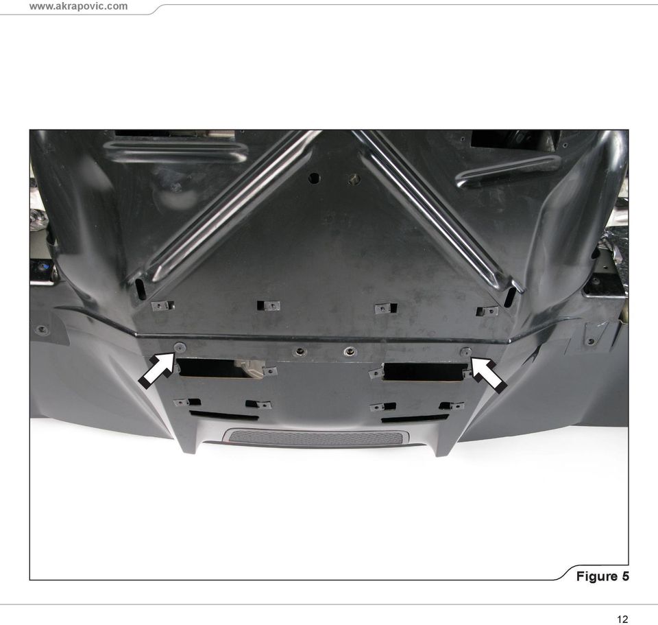
11 2. Unscrew the marked bolts and remove the diffuser off the vehicle (Figure 4, 5). WARNING: make sure, not to injure yourself or damage any part of the vehicle during this process! Figure 4 11

12 Figure 5 12
13 3. Unscrew the marked bolts on both sides of the vehicle and carefully remove the wheel arch panels heat shields (Figure 6). WARNING: make sure, not to injure yourself or damage any part of the vehicle during this process! Figure 6 13

14 4. Disconnect the marked electrical connector on the left side of the vehicle (Figure 7). WARNING: make sure, not to damage the connector or any other part of the vehicle during this process! Figure 7 14

15 5. Unscrew the marked bolts on both sides of the vehicle (Figure 8). Figure 8 15
.")
16 6. Undo and disconnect the number plate s lights and unscrew marked bolts (Figure 9). WARNING: make sure, not to damage any part of the vehicle during this process! Figure 9 16

17 7. Unscrew the marked bolts (Figure 10). Figure 10 17
. Figure")
18 8. Unscrew the marked bolts on both sides of the vehicle (Figure 11). Figure 11 18
.")
19 9. Unscrew the marked nuts on both sides of the pop-up spoiler and remove the spoiler off the vehicle (Figure 12). WARNING: make sure, not to damage any part of the vehicle during this process! Figure 12 19

20 10. Unscrew the marked bolts on both and nuts sides of the vehicle (Figure 13). Figure 13 20
.")
21 11. Disconnect the marked electrical connector on the right side of the vehicle (Figure 14). WARNING: make sure, not to damage the connector or any other part of the vehicle during this process! Figure 14 21
22 12. Disconnect the marked electrical connectors and carefully remove the tail trim off the vehicle (Figure 15). WARNING: make sure, not to damage the connectors, tail trim or any other part of the vehicle during this process! Figure 15 22
23 13. Disconnect the marked electrical connector and carefully remove the bumper trim panel off the vehicle (Figure 16). WARNING: make sure, not to damage the connector, bumper trim panel or any other part of the vehicle during this process! Figure 16 23
24 14. Cut the marked tie wraps and disconnect the marked electrical connectors and remove the wiring harness out of the bumper carrier (Figure 17, 18). WARNING: make sure, not to damage the wiring harness, connectors or any other part of the vehicle during this process! Figure 17 24
25 Figure 18 25
26 15. Pull the vacuum tubes off both exhaust valves actuators (Figure 19). Unscrew the marked nuts and bolts on both sides of the vehicle and remove bumper carrier (Figure 19, 20). WARNING: make sure, not to damage any part of the vehicle during this process! Figure 19 26
27 Figure 20 27
28 16. Disconnect the tail lights electrical connectors, unscrew the marked nuts and bolts on both sides of the vehicle and remove the tail lights off the vehicle (Figure 21, 22, 23). WARNING: make sure, not to damage the connectors, tail lights or any other part of the vehicle during this process! Figure 21 28
29 Figure 22 29
30 Figure 23 30
31 17. Unscrew the marked nuts and bolts on both sides of the vehicle and carefully remove the tail lights heat shields (Figure 24, 25). Figure 24 31
32 Figure 25 32
33 18. Unscrew the marked heat shield s bolts on both sides of the vehicle (Figure 26). Figure 26 33
34 19. For easier dismounting of upper muffler s bolts, unscrew the marked nuts on both sides of the vehicle and partially remove both air blowers (Figure 27). Figure 27 34
35 20. Unscrew the muffler s connection clamps on both sides of the engine (Figure 28). Figure 28 35
36 21. For R8 FL model only: carefully dismount both air boxes and unscrew the muffler s connection clamps on both sides of the engine (Figure 29, 30). Figure 29 36
37 Figure 30 37
38 22. Unscrew the marked bolts on both sides of the muffler and carefully remove the muffler off the vehicle (Figure 31). WARNING: make sure, not to damage any part of the vehicle during this process! Figure 31 38
39 23. Unscrew the marked bolts and carefully remove the front part of the muffler s heat shield (Figure 32). WARNING: make sure, not to damage the heat shield during this process! Figure 32 39
40 24. Undo the marked spring clip and remove the spring and washer on both sides of the muffler, than carefully remove the rear part of the muffler s heat shield (Figure 33). WARNING: make sure, not to damage the heat shield during this process! Figure 33 40
41 25. Carefully pull the vacuum rubber tubes with heat protection off the metal vacuum tubes on both sides of the vehicle (Figure 34). WARNING: make sure, not to damage the tubes heat protection during this process! Figure 34 41
42 26. Carefully remove the heat protection off the rubber vacuum tubes (Figure 35). WARNING: make sure, not to damage the tubes heat protection during this process! Figure 35 42
43 27. For R8 model only: Unscrew and remove both tail pipes off the bumper trim panel (Figure 36). WARNING: make sure, not to damage the bumper trim panel during this process! Figure 36 43
44 28. For R8 FL model only: unscrew and remove both tail pipes off the bumper trim panel (Figure 37, 38). WARNING: make sure, not to damage the bumper trim panel during this process! Figure 37 44
45 Figure 38 45
46 INSTALLATION OF THE AKRAPOVIČ EXHAUST SYSTEM: 1. Assemble the stock heat protection, tape clamps and rubber vacuum tubes, as shown (Figure 39). CAUTION: do not tighten the clamps yet! Figure 39 46
47 2. Mount the rear part of the stock muffler s heat shield onto the Akrapovič muffler, using stock washers, springs and spring clips (Figure 40). WARNING: make sure, not to damage the muffler or heat shield during this process! Figure 40 47
48 3. Attach the rubber vacuum tubes from Akrapovič installation kit onto the both exhaust valve actuators and tighten the clamps (Figure 41). WARNING: make sure, not to damage the tube s heat protection during this process! 2Nm 1.4ftlb Figure 41 48
49 4. Mount the front part of the stock muffler s heat shield onto the Akrapovič muffler, using stock bolts (Figure 42). CAUTION: make sure, that vacuum tubes are not bent or obstruct in any way! WARNING: make sure, not to damage the heat shields during this process! 3.9Nm 2.9ftlb Figure 42 49
50 5. For R8 FL model only: use bolts from Akrapovič installation kit in the marked positions (Figure 43). BOLT FROM AKR INSTALLATION KIT! BOLT FROM AKR. INSTALLATION KIT! Figure 43 50
51 6. Carefully attach the assembled muffler onto the chassis, using stock bolts, washers and distance bushes (Figure 44). WARNING: make sure, not to damage any part of the vehicle during this process! CAUTION: adjust the original muffler s brackets if needed! 34Nm 25ftlb 34Nm 25ftlb Figure 44 51
52 7. Tighten the stock muffler s connection clamps on both sides of the engine (Figure 45). CAUTION: make sure, that muffler s inlet flanges are correctly assembled onto the original flanges, before tightening the connection clamps! 9.8Nm 7ftlb Figure 45 52
53 8. Direct the vacuum tubes as shown, shorten the left vacuum tube to appropriate length and connect the Akrapovič vacuum tubes to the stock metal vacuum tubes on both sides of the vehicle (Figure 46, 47). WARNING: direct the vacuum tubes in such a way, that they don t touch any hot or moving parts! CAUTION: make sure, that vacuum tubes are not bent or obstruct in any way! Figure 46 53
54 Figure 47 54
55 9. For R8 model only: attach the Akrapovič Tail Pipes onto the bumper trim panel, using stock bolts. Place the washers from installation kit under the Tail Pipe s brackets (if necessary), to level them in respect to each other (Figure 48, 49). WARNING: make sure, not to damage the bumper trim panel or any other part of the vehicle during this process! Figure 48 55
56 4.9Nm 3.6ftlb Figure 49 56
57 10. For R8 FL model only: align both Akrapovič Tail Pipes in respect to the trim panel and each other. Attach the Tail Pipes using stock bolts (Figure 50). WARNING: make sure, not to damage the bumper trim panel or any other part of the vehicle during this process! 4.9Nm 3.6ftlb Figure 50 57
58 11. Replace all dismounted heat shields, bumper carrier, tail lights, tail trim, pop up spoiler, bumper trim panel, wheel arch panels, rear wheels and diffuser in the reverse order from the order in which they were removed. Check vehicle manufacturer manual for tightening torques. CAUTION: make sure, that you connect all disconnected electrical connectors! CAUTION: replace all clipped stock wiring harness tie wraps with tie wraps from installation kit! 58
59 12. For optional wireless kit only: locate the electromagnetic valve under the right wheel arch panel. Cut the wiring harness tie wrap, unscrew the valve s bracket, remove the vacuum tubes off the valve and disconnect the wiring harness-connector (Figure 51). WARNING: make sure, not to damage any part of the vehicle during this process! Figure 51 59
60 13. For optional wireless kit only: connect the Akrapovič wiring harness (female connector) to the stock electromagnetic valve (Figure 52). CAUTION: in case of broken supplied fuse, use only automotive 2A mini-blade fuse! Figure 52 60
61 14. For optional wireless kit only: connect the Akrapovič wiring harness (male connector) to the stock wiring harness (female connector), correctly couple the vacuum tubes onto the electromagnetic valve, tighten the ground connector (black thin wire) together with valve s bracket onto the chassis and secure the wiring harness, using 250mm tie wrap from installation kit (Figure 53). WARNING: make sure, not to damage the wiring harness during this process! 4.9Nm 3.6ftlb Figure 53 61
62 15. For optional wireless kit only: direct the Akrapovič wiring harness into the engine compartment and connect it to the transmitter (Figure 54). WARNING: make sure, not to damage the wiring harness or transmitter during this process! Figure 54 62
63 16. For optional wireless kit only: pull the heat shrinkable insulation over the connector and carefully heat it, using heat gun (Figure 55). WARNING: make sure, not to damage the wiring harness or transmitter during this process! Figure 55 63
64 17. For optional wireless kit only: attach the transmitter onto the chassis, using 360mm tie wrap from installation kit (Figure 56). WARNING: make sure, not to damage the wiring harness or transmitter during this process! Figure 56 64
65 CAUTION: secure all vacuum tubing connections, using clamps from Akrapovič installation kit! Install the clamps with corresponding tube clamp pliers (Figure 57). Figure 57 65
66 Final installation: WARNING: check vehicle manufacturer manual for tightening torques (for dismounted stock parts)! WARNING: make sure all the nuts and bolts are sufficiently tightened. In case the exhaust system touches the cowling or other parts, repeat the adjustment of the exhaust system or contact your authorized dealer. MAINTENANCE OF THE AKRAPOVIČ EXHAUST SYSTEM: 1. Clean the titanium exhaust components with a multi-purpose spray lubricant (WD-40 or equivalent), carbon fiber exhaust components with soft and dry cloth and stainless steel components with soft cloth sprayed with contact cleaner, then wipe with soft and dry cloth. A change in the color of the exhaust system is normal due to high temperatures. 2. Periodically make sure all the bolts and springs are sufficiently tight. WARNING: clean all exhaust components before the first start of the engine or the stains will burn onto the surfaces! IT IS NORMAL FOR WHITE SMOKE TO COME OUT OF THE MUFFLER AT FIRST OPERATION. DO NOT STAND BEHIND THE MUFFLER AT FIRST OPERATION. DO NOT USE AUTOMOTIVE WHEEL CLEANERS OR ANY CLEANING PRODUCTS WHICH CONTAIN ACIDIC ADDITIVES TO CLEAN THE AKRAPOVIČ EXHAUST SYSTEMS. 66
67 WARNING Please note that certain aftermarket exhaust systems may not comply with applicable California laws and regulations, and may therefore be prohibited for use on California highways or roads, or on roads or vehicles otherwise subject to emissions control requirements. Akrapovič exhaust systems for automobiles and motorcycles mounted downstream of the catalytic converter (also known as cat-back systems ) are considered replacement parts in California by the California Air Resources Board (CARB), and do not require an exemption or executive order from CARB to be sold in California. However, California prohibits the use of any aftermarket exhaust system that modifies, removes or replaces original equipment catalysts, unless CARB has issued an Executive Order as to such part or system. Further, Akrapovič parts or exhaust systems used or intended for use on racing vehicles (i.e. a competition vehicle used exclusively for competition on closed-course circuits) do not require an exemption or Executive Order from CARB to be sold in California. However, such parts are prohibited from use on California public highways or roads, even if occasionally used off-road. 67
68 *503175*
AKRAPOVIC SLIP-ON EXHAUST SYSTEM for the HONDA CB1000R
 Installation instructions: *502131* AKRAPOVIC SLIP-ON EXHAUST SYSTEM for the HONDA CB1000R Congratulations on purchasing an Akrapovic exhaust system. Please read these installation instructions carefully.
Installation Guide 2010 BMW S1000RR Full Exhaust System
 Installation Guide 2010 BMW S1000RR Full Exhaust System!! THIS PRODUCT IS DESIGNED FOR USE IN CLOSED COURSE RACING AND IS NOT INTENDED FOR HIGHWAY USE!! Congratulations on the purchase of your new TaylorMade
system in the world. your vehicle. We pride feedback Sincerely, President
 Thank you for purchasing a CORSA Performance exhaust system, the best premium exhaust system in the world. If this is your first CORSA Performance exhaust system, I would like to welcomee you to the CORSA
This kit may void factory warranty please check with manufacturer.
 Mfg Company TM Thank you for purchasing a Sinister Manufacturing Company EGR delete kit. Precision manufactured using aircraft quality 304 stainless steel and billet aluminum; this EGR kit is designed
This kit may void factory warranty please check with manufacturer.
 Thank you for purchasing a Sinister Manufacturing Company EGR delete kit. Precision manufactured using the highest grade 304 stainless steel and 6061 billet aluminum; this EGR kit is designed to endure
DYNA RIDER FOOTBOARD KIT
 -J0 REV. 0-0-0 DYNA RIDER FOOTBOARD KIT GENERAL Kit Number 000 Models For model fitment information, see the P&A Retail Catalog or the Parts and Accessories section of www.harley-davidson.com (English
LG G5 Chassis Brace Gen 5 Camaro THE MOST POWERFUL HEADERS ON THE PLANET Brought to you by LG Motorsports 972-429-1963
 LG G5 Chassis Brace Gen 5 Camaro THE MOST POWERFUL HEADERS ON THE PLANET Brought to you by LG Motorsports 972-429-1963 Thank you for purchasing LG Motorsports products for your Gen 5 Camaro. Parts Inventory:
INSTALLATION INSTRUCTIONS: HARLEY-DAVIDSON DYNA HI-OUTPUT GRENADES 2-INTO-2 PART# 16899/16896/46896/46899
 INSTALLATION INSTRUCTIONS: HARLEY-DAVIDSON DYNA HI-OUTPUT GRENADES 2-INTO-2 PART# 16899/16896/46896/46899 Congratulations, you have purchased the finest exhaust system available for your motorcycle. Your
CorkSport Mazdaspeed 6 Rear Sway Bar 2006-2007 Mazdaspeed 6
 CorkSport Mazdaspeed 6 Rear Sway Bar 2006-2007 Mazdaspeed 6 Pre-Installation Notes: The CorkSport Rear Sway Bar is a great addition to improving the handling performance to the Mazdaspeed 6. It will minimize
COOLING SYSTEM Section Page
 5 COOLING SYSTEM Section Page 5.1 COOLANT PRE-HEATER... 5-3 5.2 COOLANT PUMP NON-EGR ENGINE... 5-7 5.3 COOLANT PUMP EGR ENGINE... 5-13 5.4 FRONT CONNECTOR HOUSING NON-EGR ENGINE... 5-17 5.5 FRONT CONNECTOR
INSTALLATION INSTRUCTIONS FOR 2006-2009 VW MK5
 CI100018 INSTALLATION INSTRUCTIONS FOR 2006-2009 VW MK5 Rabbit, Jetta 2.5L These instructions are applicable to vehicles equipped with either manual or automatic transmissions Thank you for choosing to
TJ Quick Disconnect Instructions
 1 TJ Quick Disconnect Instructions www.teraflex.com Kit #17012 Kit #17092 Kit #17010 Kit #17090 Important Notes: Prior to beginning this or any installation read these instructions to familiarize yourself
INSTALLATION INSTRUCTIONS. 6111 Air Spring Kit 2011+ Ford F250/F-350 Single Wheel 2WD 2011+ Ford F350 Dually 2WD IMPORTANT NOTES
 INSTALLATION INSTRUCTIONS 6111 Air Spring Kit 2011+ Ford F250/F-350 Single Wheel 2WD 2011+ Ford F350 Dually 2WD Thank you for purchasing a quality Hellwig Product. PLEASE READ THIS INSTRUCTION SHEET COMPLETELY
INSTALLATION INSTRUCTIONS BL-8704
 INSTALLATION INSTRUCTIONS BL-8704 EXPOSED BLACK LEVER THERMOSTATIC MIXING VALVE WITH RISER KIT, HANDSET, LEVER DIVERTER, 8 ROSE AND ADJUSTABLE RISER PIPE BRACKET. Dimensions in Inches (& Millimetres) 1
Installation Instructions 4508 4508S
 SYMPHONY Spread Lavatory Faucet with Speed Connect Drain Congratulations on purchasing your American Standard faucet with Speed Connect drain, a feature found only on American Standard faucets. Speed Connect
INSTALLATION INSTRUCTIONS. 6108 Air Spring Kit 2011+ Ford F250 Single Wheel 4WD 2011+ Ford F350 Dually 4WD (2011 F350 Single Wheel 4WD use p/n 6113)
") INSTALLATION INSTRUCTIONS 6108 Air Spring Kit 2011+ Ford F250 Single Wheel 4WD 2011+ Ford F350 Dually 4WD (2011 F350 Single Wheel 4WD use p/n 6113) Thank you for purchasing a quality Hellwig Product. PLEASE
INSTALLATION INSTRUCTIONS 6108 Air Spring Kit 2011+ Ford F250 Single Wheel 4WD 2011+ Ford F350 Dually 4WD (2011 F350 Single Wheel 4WD use p/n 6113) Thank you for purchasing a quality Hellwig Product. PLEASE
Installation Instructions Avalanche XUV Cap IMPORTANT! IMPORTANT!
 Installation Instructions Avalanche XUV Cap IMPORTANT! Read all instructions carefully before commencing any work. Always wear safety equipment. Some installation steps will require two or more installers.
INSTALLATION INSTRUCTIONS MK-8704
 INSTALLATION INSTRUCTIONS MK-8704 EXPOSED MACKINTOSH THERMOSTATIC MIXING VALVE WITH RISER KIT, HANDSET, LEVER DIVERTER, 8 ROSE AND ADJUSTABLE RISER PIPE BRACKET. Dimensions in Inches (& Millimetres) 1
Table of Contents WARNING SYMBOLS AND DEFINITIONS
 Table of Contents SAFETY INSTALLATION OPERATION MAINTENANCE Safety... 2 Specifications... 4 Installation... 5 Operation... 8 WARNING SYMBOLS AND DEFINITIONS Maintenance... 9 Parts List and Assembly Diagram...
2012-15 Porsche 991S SwitchPath TM Exhaust INSTALLATION GUIDE
 PERFORMANCE ENGINEERING FOR EUROPEAN AUTOS INSTALLATION GUIDE 2012-15 Porsche 991S SwitchPath TM Exhaust Congratulations on your purchase of the AWE Tuning SwitchPath TM Exhaust for the 2012-15 Porsche
FRONT BUMPER INSTALLATION INSTRUCTIONS 2007-2011 DODGE / MERCEDES SPRINTER
 Aluminess Products Inc 9402 Wheatlands Ct. #A Santee, CA 92071 619-449-9930 FRONT BUMPER INSTALLATION INSTRUCTIONS 2007-2011 DODGE / MERCEDES SPRINTER Please read before beginning Stainless steel hardware
Front axle components, overview
 just a test. Front axle components, overview 40-1 General Information Load bearing components and parts of the suspension must not be welded or straightened. Vehicles without drive axle must not be moved,
Thank You For Choosing. INSTALLATION INSTRUCTIONS Portal Gear Hubs Polaris RZR 800. (installation performed on 60 Model) (Right) (Left)
 (Right) (Left)") 740B Clifty Drive Madison, Indiana 47250 812-574-7777 INSTALLATION INSTRUCTIONS Portal Gear Hubs Polaris RZR 800 A (installation performed on 60 Model) Item Description Qty A Rotor 4 B Gear Box, L 2 C
740B Clifty Drive Madison, Indiana 47250 812-574-7777 INSTALLATION INSTRUCTIONS Portal Gear Hubs Polaris RZR 800 A (installation performed on 60 Model) Item Description Qty A Rotor 4 B Gear Box, L 2 C
Installation Instructions
 520 Installation Instructions Thank you very much for purchasing PIAA product. Please read this entire manual before installation and use of this product. For Installers Please give this Installation Manual
Cooling system components
 Page 1 / 33 19-1 Cooling system components Caution! When doing any repair work, especially in the engine compartment, pay attention to the following due to clearance issues: Route lines of all types (e.g.
SALEEN SPEEDLAB SERIES VI STANDARD SC UPGRADE KIT
 SALEEN SPEEDLAB SERIES VI STANDARD SC UPGRADE KIT INSTALLATION MANUAL: 2005 MUSTANG 4.6 3V MANUAL P/N: 10-8002-C14338C SUPERCHARGER KIT P/N: 10-1607-B14083* Saleen Performance, Inc. 1225 East Maple Rd.,
5800 Temperature Sensor Cable Assembly
 5800 Temperature Sensor Cable Assembly Removal and Replacement Instruction Sheet #60-4702-070 Revision D, January 14, 2013 Overview The 5800 has two refrigeration temperature sensors, one attached to the
WARNING TO END USER, INSTALLER AND SELLER OF THIS PART!
 WARNING TO END USER, INSTALLER AND SELLER OF THIS PART! By installing this part you are accepting full responsibility and liability for proper wheel and tire fitment after installation. It is the installer
BUILT-IN DISHWASHER INSTALLATION INSTRUCTIONS
 BUILT-IN DISHWASHER INSTALLATION INSTRUCTIONS PLEASE READ COMPLETE INSTRUCTIONS BEFORE YOU BEGIN LEAVE INSTALLATION INSTRUCTIONS AND USER'S GUIDE WITH OWNER ALL ELECTRIC WIRING AND PLUMBING MUST BE DONE
Equipped with AEM Dryflow Filter No Oil Required! INSTALLATION INSTRUCTIONS PART NUMBER 21-754DS. 2012-2015 BMW 335i 3.0L
 Equipped with AEM Dryflow Filter No Oil Required! INSTALLATION INSTRUCTIONS PART NUMBER 21-754DS 2012-2015 BMW 335i 3.0L 1 ITEM NO. PART NUMBER DESCRIPTION QTY. 1 21-2057DK AIR FILTER 1 2 9-0442 TUBE;
Solstice/Sky Water Pump Replacement
 Solstice/Sky Water Pump Replacement The water pump on the Solstice/Sky is starting to need replacement on some vehicles. This guide will help in replacing the water pump while the engine is still in the
AWE Tuning Air/Air Intercooler Kit for 2000-04 Audi 2.7T
 AWE Tuning Air/Air Intercooler Kit for 2000-04 Audi 2.7T Congratulations on your purchase of the AWE Tuning Intercoolers for your 2.7T Audi. Hundreds of hours of design and operational testing were spent
- power windows - alarm system - electric door mirror control - door warning light - central locking - seat memory
 Door Wiring Harness Plug Connections Binder -, Electrics Vehicle Type: (86) Model Year: 7 (V) Concern: Door wiring harness plug connections X11 / X12. Information: The rubber boot for the door connector
Installation manual. 1.75 front leveling kit. 2011 Dodge Durango 2011-2014 Jeep Grand Cherokee. Part # 42006. Part # 42006
 Installation manual 1.75 front leveling kit 2011 Dodge Durango 2011-2014 Jeep Grand Cherokee Part # 42006 sj02282011rev.01 Part # 42006 2011-2014 Dodge Durango 2011 Jeep Grand Cherokee 1.75 front leveling
2015+ VW GOLF R SwitchPath and Track Edition Exhaust INSTALLATION GUIDE
 PERFORMANCE ENGINEERING FOR EUROPEAN AUTOS INSTALLATION GUIDE 05+ VW GOLF R SwitchPath and Track Edition Exhaust Congratulations on your purchase of the AWE Tuning SwitchPath and Track Edition Exhausts
BILLET HEADLAMP SHELL
 -J008 REV. 007-07- BILLET HEADLAMP SHELL GENERAL Kit Number 770-0 Models For model fitment information, please see the P&A Retail Catalog or the Parts and Accessories section of www.harleydavidson.com
15GAL STEEL OIL DRAIN WITH 110V PUMP
 15GAL STEEL OIL DRAIN WITH 110V PUMP OWNER S MANUAL WARNING: Read carefully and understand all ASSEMBLY AND OPERATION INSTRUCTIONS before operating. Failure to follow the safety rules and other basic safety
AIR-SUSPENSION. Art. nr.: L.L200.07.C.M. Auxiliary Air Suspension. Designed for: Mitsubishi L200. From: 2007& UP RDW 71/320-0569
 AIR-SUSPENSION Dunlop Systems and Components Het Wegdam 22 7496 CA Hengevelde The Netherlands Tel.: +31-547-333065 Fax: +31-547-333068 Website: www.dunlopsystems.com Art. nr.: L.L200.07.C.M Designed for:
Instruction Manual. Please read the manual carefully before installing and using this product. This product is for off road use only.
 Instruction Manual Please read the manual carefully before installing and using this product. This product is for off road use only. PARTS 1. LIST BLOW OFF VALVE 1 5. GASKET 1 2. VACUUM HOSE 4.5φ 1 6.
Thank You For Choosing. INSTALLATION INSTRUCTIONS Portal Gear Hubs Polaris RZR XP 900 Crew. (Right) (Left)
 (Left)") 740B Clifty Drive Madison, Indiana 47250 812-574-7777 INSTALLATION INSTRUCTIONS Portal Gear Hubs Polaris RZR XP 900 Crew A Item Description Qty A Rotor 4 B Gear Box, L 2 C Gear Box, R 2 D Gasket 4 E Cap
740B Clifty Drive Madison, Indiana 47250 812-574-7777 INSTALLATION INSTRUCTIONS Portal Gear Hubs Polaris RZR XP 900 Crew A Item Description Qty A Rotor 4 B Gear Box, L 2 C Gear Box, R 2 D Gasket 4 E Cap
!"#$%&'()*#%+!,-./ 011-2,.%34$5')4564%7"&8*# 9%8:;<%0<17%&=&2$'#)=
*#%+!,-./ 011-2,.%34$5')4564%7&8*# 9%8:;<%0<17%&=&2$'#)=") !"#$%&'()*#%+!,-./ 011-2,.%34$5')4564%7"&8*# 9%8:;
!"#$%&'()*#%+!,-./ 011-2,.%34$5')4564%7"&8*# 9%8:;
INSTALLATION INSTRUCTIONS PART NUMBER:
 Equipped with AEM Dryflow Filter No Oil Required! INSTALLATION INSTRUCTIONS PART NUMBER: 21-475B (Blue Finish) 21-475C (Gun Metal Grey Finish) 21-475P (Vacuum Metalized Chrome-VMC) 21-475R (Red Finish)
INSTALL/REMOVAL INSTRUCTIONS: WINDOW REGULATOR
 REMOVAL/INSTALL OF WINDOW REGULATOR (741-306) Honda Accord 2003 07 General Tech Tips: Use painter s tape rather than duct tape to secure window. It will not damage paint or leave sticky residue. A plastic
Front brakes (FN- 3), servicing
, servicing") j a t Front brakes (FN- 3), servicing 46-1 Front brakes, servicing Note: Install complete repair kit. After replacing brake pads and before moving vehicle, depress brake pedal several times firmly to properly
j a t Front brakes (FN- 3), servicing 46-1 Front brakes, servicing Note: Install complete repair kit. After replacing brake pads and before moving vehicle, depress brake pedal several times firmly to properly
Drive shaft, servicing
 Volkswagen Passat B6 - Drive shaft, servicing Стр. 1 из 41 40-7 Drive shaft, servicing Drive shafts, overview I - Assembly overview: Drive axle with CV joint VL100 40-7, Drive axle with CV joint VL100,
SCION FR-S 2013 - PERFORMANCE AIR INTAKE Preparation 2.0L F-4
 Preparation 2.0L F-4 Part Number: PTR03-18130 Please see Page 12 for important Care and Maintenance information! Kit Contents Item # Qty. Service Part # Description 1 1 PTR03-18130-AC TRD Air Box Base
2011-14 F250 6 RADIUS ARM KIT
 92154000 Thank you for choosing Rough Country for your suspension needs. 2011-14 F250 6 RADIUS ARM KIT Rough Country recommends a certified technician installs this system. In addition to these instructions,
TOLL FREE: (866) 591-7792. E-Mail: techmail@vigoindustries.com. www.vigoindustries.com VANITY SPECIFICATIONS. VANITY COMPONENTS Model VG09042K1
 591-7792. E-Mail: techmail@vigoindustries.com. www.vigoindustries.com VANITY SPECIFICATIONS. VANITY COMPONENTS Model VG09042K1") VANITY SPECIFICATIONS VANITY COMPONENTS Model VG09042K1 MODEL VG09042K1 FEATURES Freestanding cabinet Soft closing sliding cabinet drawer hardware White, single hole ceramic sink Cabinet ships assembled
VANITY SPECIFICATIONS VANITY COMPONENTS Model VG09042K1 MODEL VG09042K1 FEATURES Freestanding cabinet Soft closing sliding cabinet drawer hardware White, single hole ceramic sink Cabinet ships assembled
Cooling system components, removing and installing
 Engine BHW Cooling system components, removing and installing Page 1 / 24 19-1 Cooling system components, removing and installing Warning! When doing any repair work, especially in the engine compartment,
Owner s Manual Read and keep this manual. Patents World Wide
 Owner s Manual Read and keep this manual. Patents World Wide S & S Industries, Inc., Sarasota, FL, USA www.trail-gator.com Copyright 2008 All Rights Reserved The following manual is provided to assist
OVEN PARTS For Models:GSC308PJB05, GSC308PJQ05, GSC308PJT05, GSC308PJS05 (Black) (White) (Biscuit) (Black Stainless)
 (White) (Biscuit) (Black Stainless)") OVEN PARTS 30" BUILT IN ELECTRIC COMBO SENSOR/SC (GOLD LINE) 3 05 Litho In U.S.A. (cre) 1 Part No. Rev.A OVEN PARTS 1 Literature Parts 4455994 Installation Instructions Use & Care Guide 8300346 Microwave
OVEN PARTS 30" BUILT IN ELECTRIC COMBO SENSOR/SC (GOLD LINE) 3 05 Litho In U.S.A. (cre) 1 Part No. Rev.A OVEN PARTS 1 Literature Parts 4455994 Installation Instructions Use & Care Guide 8300346 Microwave
Installation Instructions 6028.801
 DAZZLE Installation Instructions 08.80 Spread Lavatory Faucet with Speed Connect Drain* Congratulations on purchasing your American Standard faucet with Speed Connect drain, a feature found only on American
INSTALL/REMOVAL INSTRUCTIONS: WINDOW LIFT MOTOR
 REMOVAL/INSTALL OF WINDOW LIFT MOTOR (742-273) Ford Expedition 1997 2002, Lincoln Navigator 1998 2002, Ford F-150 Super Crew Cab 2001 General Tech Tips: Use painter s tape rather than duct tape to secure
Volkswagen Jetta, Golf, GTI 1999, 2000 Brake System 47 Brakes - Hydraulic Components (Page GR-47)
") 47 Brakes - Hydraulic Components (Page GR-47) FS III front brake calipers, servicing Front brake caliper piston, removing and installing FN 3 front brake calipers, servicing Front caliper piston, removing
47 Brakes - Hydraulic Components (Page GR-47) FS III front brake calipers, servicing Front brake caliper piston, removing and installing FN 3 front brake calipers, servicing Front caliper piston, removing
SCION tc 2005-2008 COIL OVER SUSPENSION Preparation
 SCION tc 2005-2008 COIL OVER SUSPENSION Preparation Part Number: PTR11-21070 NOTE: Part number of this accessory may not be the same as the part number shown. Kit Contents: Item # Quantity Reqd. Description
INSTRUCTIONS. FLHR/C/S (Road King) FRONT END LOWERING KIT 1WARNING -J03242 REV. 10-19-04. General. Removal (Left and Right Forks) Kit Number 54614-05
 FRONT END LOWERING KIT 1WARNING -J03242 REV. 10-19-04. General. Removal (Left and Right Forks) Kit Number 54614-05") INSTRUCTIONS -J04 REV. 0-9-04 General FLHR/C/S (Road King) FRONT END LOWERING KIT This kit is designed for installation on 00 and later FLHR/C/S Model Motorcycles. Road King models use the conventional
INSTRUCTIONS -J04 REV. 0-9-04 General FLHR/C/S (Road King) FRONT END LOWERING KIT This kit is designed for installation on 00 and later FLHR/C/S Model Motorcycles. Road King models use the conventional
Slide the new steering column shaft through the steering column from the driver compartment.
 Slide the new steering column shaft through the steering column from the driver compartment. Push the column shaft through the steering column until the machined end is out past the column lower bushing.
Depending on which elastic support you have you can secure the V2 power unit to the following seat bracket tubes: EXTERNAL DIAMETER 27.
 ASSEMBLY 1 - EPS V2 POWER UNIT (SOLUTION 5) 1.1 - POSITIONING INSIDE THE SEAT TUBE WITH ELASTIC SUPPORT IN THE SEAT BRACKET TUBE Depending on which elastic support you have you can secure the V2 power
TABLE OF CONTENTS. Section 1 - Assembling your new pit bike.
 Orion Pit Bike Sales Owners Manual (All information and content is the property of Orion Pit Bike Sales. Any attempt to copy or resell is a direct violation of our copyright. All violators will be prosecuted)
CONGRATULATIONS! TABLE OF CONTENTS. 1 Safety Warnings 2 About Your Wheels 3 Setting Up Your Wheels 7 Care and Cleaning 8 Warranty
 WHEEL MANUAL CONGRATULATIONS! Congratulations on your purchase of Oval Concepts Wheels. Developed to perform at a high level, it is important that you follow the operation and maintenance instructions
http://waterheatertimer.org/troubleshoot-rheem-tankless-water-heater.html
 http://waterheatertimer.org/troubleshoot-rheem-tankless-water-heater.html TECHNICAL SERVICE DEPARTMENT Removal, Cleaning, & Reinstallation of the Burner Assembly For models 74 & GT199 Required tools -
REMOVAL AND INSTALLATION
 303-01C-1 REMOVAL AND INSTALLATION Engine Body On Special Tool(s) Adapter For 303-D043 303-D043-02 or equivalent Special Tool(s) 303-01C-1 Turbocharger Lifting Bracket 303-1266 Wrench, Fan Clutch Nut 303-214
2005-2007 Ford Focus Front Brake Rotors
 2005-2007 Ford Focus Front Brake Rotors Replacement Replacing the rotors in 2005-2007 Ford Focus models with rear drum brakes. Written By: David Hodson INTRODUCTION The steps in this guide are used to
Installation Instructions GOOSENECK MOUNTING KIT Chevrolet/GMC 1500/2500/3500 All except 4-door Crew-Cab
 GOOSENECK MOUNTING KIT Equipment Required: Fastener Kit: F Wrenches: 3/4, 7/8, 15/16 Drill Bits: 1/4 Other Tools: Drill WARNING: Under no circumstances do we recommend exceeding the towing vehicle manufacturers
Cooling system components, removing and installing
 Volkswagen Touareg 3.2 - Cooling system components, removing and installing Page 1 / 24 19-1 Cooling system components, removing and installing Warning! Hot steam may escape when opening expansion tank.
Little British Car Co.
 Little British Car Co. 29311 Aranel, Farmington Hills, MI 48334-2815, USA Tel: 248 489 0022 or 800 637 9640 Fax: 248 489 9665 On the web at: www.lbcarco.com E-mail: LBCarco@LBCarCo.com MGB Tube Rear Shock
STEADYfast Stabilizer Installation Notes Fifth Wheel and Travel Trailers 11/23/13
 STEADYfast Stabilizer Installation Notes Fifth Wheel and Travel Trailers 11/23/13 (See Supplemental Instructions for trailers with heavy duty round footplates and/or Power Leveling Systems) PHONE SUPPORT
VW GOLF Mk4 TDI FRONT MOUNTING INTERCOOLER INSTALLATION INSTRUCTIONS
 VW GOLF Mk4 TDI FRONT MOUNTING INTERCOOLER INSTALLATION INSTRUCTIONS Tools required: 10mm/13mm socket and 3/8 drive ratchet with extension Torx T20/25/30 screwdrivers or bits Phillips head screwdriver,
INSIDE ENGINE COMPARTMENT TOYOTA AIR CONDITIONING ENGLISH EUROPE,GENERAL,AUSTRALIA
 INSIDE ENGINE COMPARTMENT TOYOTA AIR CONDITIONING ENGLISH EUROPE,GENERAL,AUSTRALIA INTRODUCTION IMPORTANT NOTICE This manual has been designed for technicians who are qualified and educated in the proper
Service Manual Supplement
 Volvo Trucks North America, Inc. Greensboro, NC USA This Service Bulletin is a supplement to Service Manual, Group, Anti-lock Brake System (ABS), Bendix, VNL, VNM publication number PV /. Service Manual
Installation instruction do88 Intercooler for Volvo S40 / V50 / C30
 Installation instruction do88 Intercooler for Volvo S40 / V50 / C30 This instruction shows how to replace the OEM intercooler with our performance intercooler. 2. 3. 1. 4. 5. Part number: ICM-170 6. At
tire inflator with pressure gauge
 tire inflator with pressure gauge Model 95583 Assembly And Operation Instructions Due to continuing improvements, actual product may differ slightly from the product described herein. 3491 Mission Oaks
INSTALLATION INSTRUCTIONS
 INSTALLATION INSTRUCTIONS Electric Vacuum Pump Kit 28146 Thank you for choosing STAINLESS STEEL BRAKES CORPORATION for your braking needs. Pleases take the time to read and carefully follow these instructions
16 April 2012 1032011-F 1994-2002 Dodge Adjustable Track bar with Relocation Bracket 1
 16 April 2012 1032011-F 1994-2002 Dodge Adjustable Track bar with Relocation Bracket 1 BD Adjustable Track Bar w/bracket Dodge 2500-3500 4WD Models 1994-2002 Dodge 1500 4WD Model 1994-2001 P/N# 1032011-F
M-9424-463V Intake Manifold INSTALLATION INSTRUCTIONS
 Please visit www.fordracingparts.com for the most current instruction information!!! PLEASE READ ALL OF THE FOLLOWING INSTRUCTIONS CAREFULLY PRIOR TO INSTALLATION. AT ANY TIME YOU DO NOT UNDERSTAND THE
Step 1. Item 6. Item 1
 Voltage Regulators QD3/T350 Motor Replacement Kit Kit Number 57A63675100B Service Information S225-50-35 Contents General..................................... 1 Parts Supplied...............................
ALL WEATHER W-SERIES QUARTZ TUBE ELECTRIC INFRARED RADIANT HEATER INSTALLATION USE & CARE MANUAL
 ALL WEATHER W-SERIES QUARTZ TUBE ELECTRIC INFRARED RADIANT HEATER TABLE OF CONTENTS: INSTALLATION USE & CARE MANUAL IMPORTANT INFORMATION Assembly Instructions 2 Wiring Instructions 2 Outdoor Installation
Multiport Spill Containment with Defender Spill Containers
 Multiport Spill Containment with Defender Spill Containers Retrofit Installation Guide Overview Franklin Fueling Systems 3760 Marsh Rd. Madison, WI 53718 USA Tel: +1 608 838 8786 800 225 9787 Fax: +1 608
FRONT TURN SIGNAL RELOCATION KIT
 -J0 REV. 00-0-0 FRONT TURN SIGNAL RELOCATION KIT GENERAL Kit Number -0 Models This kit fits 00 and later Dyna model motorcycles (except FXDSE), relocating the front turn signal from the handlebars to the
FOR ANY QUESTIONS, PLEASE CALL US @ 727.347.9915 M-F 8:00a.m.-8:00p.m. EST. REAR BRAKES 1 AEROSPACE COMPONENTS 727.347.9915
 REAR BRAKES 1 AEROSPACE COMPONENTS 727.347.9915 REAR BRAKES Before getting started, remove all stock braking components. Pre-assembly of parts: Clean the bolts and the threads in the hat with acetone.
Owners & Installation Manual for the Sheridan, Mountainair, Pine Valley and Old Forge Ceiling Fan Family
 Owners & Installation Manual for the Sheridan, Mountainair, Pine Valley and Old Forge Ceiling Fan Family Part of the Kiva Lighting Family Custom Lighting and Fans Since 1992 1312 12th St NW Albuquerque,
XL PREMIUM OIL COOLER KIT
 -J05 REV. 0-0-0 XL PREMIUM OIL COOLER KIT GENERAL Kit Number 0008 Models For model fitment information, see the P&A Retail Catalog or the Parts and Accessories section of www.harley-davidson.com (English
VW Caddy W21-760-3503 INSTALLATION INSTRUCTIONS
 Unit 626 Kilshane Avenue, North West Business Park, Ballycoolin, Dublin 15, Ireland Telephone: +353 1 8612 632, Fax: +353 1 8612 647, email: sales@driveriteltd.com www.driveriteltd.com VW Caddy W21-760-3503
DANGER DANGER. General Information. Safety Is Your Responsibility. Ordering Parts. Contact Information
 Safety Safety Is Your Responsibility DANGER To avoid personal injury or death, carefully read and understand all instructions pertaining to the Anthony Liftgates product. Do not attempt to install, operate,
OWNER S MANUAL DRAINVAC ATOMIK PRINTED APRIL 4-2011
 OWNER S MANUAL th DRAINVAC ATOMIK PRINTED APRIL 4-2011 INTRODUCTION We take this opportunity to express our gratitude and extend our congratulations for your decision to purchase a Drainvac product. A
Volkswagen Jetta, Golf, GTI 1999, 2000 Brake System 46 Brakes - Mechanical Components (Page GR-46)
") 46 Brakes - Mechanical Components (Page GR-46) Front brakes Brake pads, removing and installing Brake pads, removing and installing FN 3 brake caliper, servicing FS III brake caliper, servicing Rear wheel
46 Brakes - Mechanical Components (Page GR-46) Front brakes Brake pads, removing and installing Brake pads, removing and installing FN 3 brake caliper, servicing FS III brake caliper, servicing Rear wheel
Katana Supercharger Installation Instructions Rev. E Page 1 of 23
 Katana Supercharger Installation Instructions Rev. E Page 1 of 23 READ FITTING INSTRUCTIONS IN FULL BEFORE INSTALLATION This article is sold without warranty expressed or implied. No warranty or representation
TOYOTA TUNDRA 2015 Billet Grille w/led DRL
 TOYOTA TUNDRA 2015 Billet Grille w/led DRL Part Number: 00016-34088 Accessory Code: BG3000 Conflicts Models 1794 and Platinum Kit Contents Item # Quantity Reqd. Description 1 2 LED DRL 2 1 Driver Box 3
Figure 2 The fan and shroud also needs to be removed for access to the four a/c compressor bolts and removal of the compressor from the top.
 Here are some pictures to show what s required when replacing the A/C compressor, expansion valve and receiver/drier on a 2001 Volvo V70. Even if you don t replace these A/C parts these pictures can help
Heater Replacement Procedure
 Heater Replacement Procedure Oil Diffusion Pump Model ULK-10A ULK-14A Components Division, ULVAC, Inc. http://www.ulvac.co.jp/ Preface We thank you very much for purchasing our product. This manual describes
with installation dynafact boost GAUGE this manual is for use with systems 64050-64054
 owners manual with installation instructions dynafact boost GAUGE this manual is for use with systems 64050-64054 GENERAL INSTALLATION PRACTICES This manual is an installation guide for all 1. Banks DynaFact
Volkswagen B3 Passat Manual Transmission 02A 34 Manual Transmission - Controls, Assembly (Page GR-34) 02A 5-speed. Gearshift cable/lever installing
 02A 5-speed. Gearshift cable/lever installing") 34 Manual Transmission - Controls, Assembly (Page GR-34) 02A 5-speed Gearshift cable/lever installing Gearshift housing repairing Gearshift lever repairing lever/relay lever, installing Gearshift mechanism
34 Manual Transmission - Controls, Assembly (Page GR-34) 02A 5-speed Gearshift cable/lever installing Gearshift housing repairing Gearshift lever repairing lever/relay lever, installing Gearshift mechanism
Assembly overview - fuel tank
 Assembly overview - fuel tank vw-wi://rl/n.en-gb.k02589829.wi::33090894.xml?xsl=3 Page 1 of 2 Assembly overview - fuel tank 1 - Fuel tank 2 - Sleeve When removing, support using engine and gearbox jack
BILLET HEADLAMP WITH SHORT/TALL MOUNTS
 -J099 REV. 00-0- BILLET HEADLAMP WITH SHORT/TALL MOUNTS GENERAL Kit Number 9-0, 9-0 Models Kit 9-0 is a -/ inch headlamp and kit 9-0 is a -/ inch headlamp. Both kits will fit the models listed in Table.
Tablet 30W Tablet 92W
 Tablet 30W Tablet 92W Owner s Manual 1 CONTENTS TABLE OF CONTENTS Important Safety Instructions 3-4 Parts Exploded View & Identification Tablet 30 5 Tablet 92 6 Introduction Tablet 30 7-8 Tablet 92 9-10
Trillium 40 Axis Spring Tensioner Wire Replacement Instructions
 Trillium 40 Axis Spring Tensioner Wire Replacement Instructions 1 Overview The objective is to replace the broken axis spring tensioner wire. This requires the following tasks: 1. Remove the seismometer
Owner s Guide and Installation Manual. Vancouver Model Name. 21321, 21328 Model No. English Español
 For Your Records and Warranty Assistance For reference, also attach your receipt or a copy of your receipt to the manual. Vancouver Model Name 21321, 21328 Model No. Type A Models Owner s Guide and Installation
UNIVERSAL LUMBAR INSTALLATION INSTRUCTIONS
 UNIVERSAL LUMBAR INSTALLATION INSTRUCTIONS CONTENTS Parts List... 2 Parts Diagram... 2 Helpful Hints... 3 Installation... 4 Operation and Troubleshooting Guide... 6 Warranty Information... 8 Form #3132,
"Engineered to Ride, Built to Last "
 Congratulations on your purchase of an Arnott air suspension product. We at Arnott Incorporated are proud to offer a high quality product at the industry s most competitive pricing. Thank you for your