Broadband Terminated Vee Beam Wire Antenna
|
|
|
- Melvin Whitehead
- 7 years ago
- Views:
Transcription
1 Broadband Terminated Vee Beam Wire Antenna TEN-TEC Model 3402 and or MHz. THROW AWAY YOUR ANTENNA TUNER! Models 3402 and 3403 are broadband terminated vee beam wire antennas. These broadband HF antennas are small size and offer continuous coverage from 1.8 to 54 MHz ( 200ft) or 3.5 to 54 MHz ( 100ft) with VSWR of below 2:1 up to 30 MHz and below 2.5:1 from 30 to 54 MHz (typical VSWR on HF frequencies is 1.4:1). Well-suited to the amateur who has a small lot and needs a broadband antenna for full frequency coverage! In the vee-beam configuration, the antenna is unidirectional and offers significant gain at higher frequencies. In the broadside/end-fire configuration (installed similar to a traditional inverted-v dipole) the antenna is bi-directional or multi-directional, depending on frequency of operation. Broadband vee-beam offers a number of advantages over a typical flat-top multiband dipole or windom. First, continuous frequency coverage presents a low VSWR to your transceiver. This multiband wire dipole antennas does not require the use of an antenna tuner on one or more HF bands. MARS operators do not need to employ another antenna for ham bands vs. MARS coverage; the vee-beam will cover both. Third, because the antenna does not require a traditional flat-top dipole or inverted-v style installation, a more limited space can be utilized for installation of the antenna in the vee-beam configuration. The 200ft model covers MHz and is 100 ft. per side. Model 100ft model covers MHz and is only 50ft. per side! All the user needs to add is rope for support, a coax feedline, and either two ground rods or two radials depending on the desired installation configuration. From NNN0EPY/WB8MWG: Several years ago,i was looking to a good all band Antenna that I could add to my collection of wires in the backyard. I run a NDN/RDN Pactor BBS on and 7.9 MHz. Three HF radios operating 24/7 Pactor running 50 watts each on home made double bazooka dipoles. So, whatever antenna I add must get along with the others that I have on site. When talking with Bo NNN0ZLS about my situation, he recommended the Ten-Tec Antennas that he was running at two locations.

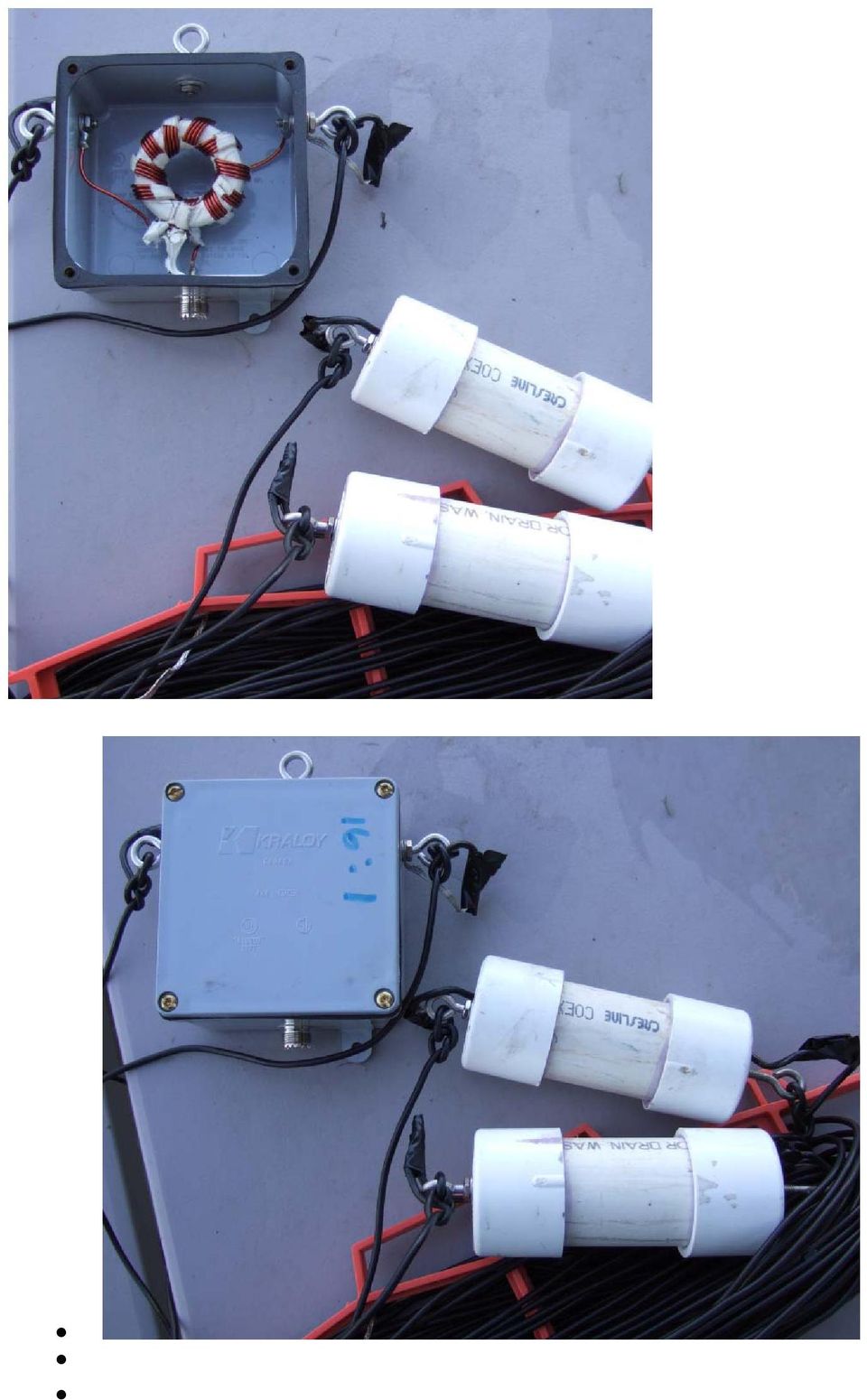
2 Bo said I use my 200 foot version more in NVIS mode at home. I run it as my ALE antenna from 2 to 27 MHz with no tuner. The center height is about 20 feet while the ends are at 8 feet or less running to ground rods. This pseudo-nvis arrangement allows good all-around coverage on the lower frequencies while the higher frequencies approach 1/4 wavelength over ground. I also use the 3.5 to 30 MHz version as my antenna for the 5 MHz ADN message switch. I run this one with a center height of 30 feet with the ends at 6-8 feet with ground rods. With no tuner, it does not require fussing with an antenna tuner as rain, snow and ice hit the antenna. I did some research and found one on Ebay and bought it. I installed it in an inverted Vee configuration off the side of a 60 ft tower on the opposite side of the three antennas for the BBS, in a 45 degree spread, terminating into, two ten ft poles mounted 87 ft from the base of the tower. At the base of the 10 ft poles are two 8 ft ground rods for each pole. How does it work? Super! NO Tuner and in the Winter when the band goes long we are still on the air. 160 meter SSB is great also. It will work from 1.8 thru 54 MHz. I get very little to no intermod with the other radios. I do have BPF filters cut for each frequency installed in the coaxial lines of each BBS antenna. I wanted another TEN-TEC 3402, and found out that TEN-TEC no longer sells or manufactures these units. So, I did some testing with the one I owned and found the Balun is 16:1 and the termination resistors are approximately 400 Ohms. I found the 16:1 balun at Wireman I bought one ready made and one in kit form. 830 CQ Toroidal, full power, 1-28 MHz, 1:1 to 16:1 ratios, voltage type. Kit contains 20 ft 200 deg. C enameled soft copper wire, T iron powder core, 3 ft fiberglass tape, instructions, reference. $14.50 Kit or $38 Assembled It was easier for me to look at one ready made unit and copy it than read the instructions. I also took some pictures for future use. Before doing this report, I called TEN-TEC and received their Blessing.

3 They asked that I send them a copy of this report. The TEN-TEC Company people are super to work with. I have a copy of the TEN-TEC pdf instructions that came with my unit that I will pass along. Technical specifications: Input power rating: 250 watts ICAS, 100 watts continuous duty. This depends on the wattage of the resistors. Feed point impedance: 50 ohms nominal Feed point VSWR: model 200, less than 2:1typical MHz, 2.5: MHz. Model 100 less than 2:1 typical MHz, 2.5: MHz. Transformer impedances: 50 ohms feed point, 800 ohms antenna. 16:1 Balun, these can be made or purchased from The wireman Termination impedance: 400 ohms typical These I scrounged at a Ham swap. 380 ohms to 420 ohms NON-INDUCTIVE will work. I mounted them in a short 1 1/2 PVC 6 long with end cap. Also Stainless Steel eyebolts ( Menards). Drill two holes in the end caps, one center for I bolts, one offset for wire. On the Termination Resistors, solder a short insulated wire on each end about 6 long. Install the eye bolts in the center hole of the end caps. Use extra nuts and washers to secure. Install the resistor in the PVC and feed a wire out the offset hole, glue the ends caps. You now have a very weather proof unit. I mounted the 16:1 Balun in a weather proof 4x4 electrical box, again Menards.

4 Element length: 100 ft, model ft, model Wire type: 14 AWG 7/22 stranded copper-clad steel. 200ft/3402 model : The Balun is centered, 90 ft to Term Resistor,10 ft to ground rod on each leg. 100ft/3403 model : The Balun is centered,40 ft to Term Resistor, 10ft to ground rod on each leg. PARTS NEEDED FT WIRE :1 BALUN (WIREMAN 830) TO 420 OHM NON-INDUCTIVE RESISTORS END CAPS 1 1/2 PVC ½ PVC plastic (MENARDS) STAINLESS STEEL EYEBOLTS (project pro # ) MENARDS WATER PROOF ELECTRICAL BOX FROM MENARDS, 4X4 WITH COVER.THE TOP AND SIDES WILL HAVE EYEBOLTS, BOTTOM WILL HAVE COAXIAL SO259 jack, see pix.
 6. 7 - STAINLESS STEEL EYEBOLTS (project pro #226-5018) MENARDS. 7. 1 - WATER PROOF ELECTRICAL BOX FROM MENARDS, 4X4 WITH COVER.")
5
6 1. Introduction Ten-Tec Model 3402 and 3403 Broadband Antennas Installation and Operation Manual PN The Ten-Tec Model 3402 Broadband Terminated Vee Beam Antenna offers continuous coverage between 1.8 and 30 MHz with a maximum VSWR of 2:1 typically 1.4:1 or less. The Model 3403 is a shorter version of the antenna that covers 3.5 to 30 MHz with a maximum VSWR of 2:1 typically 1.4:1 or less. For both models, VHF coverage is also provided for with a maximum VSWR of 2.5:1 from 30 to 54 MHz. The antennas handle 100 W in continuous-duty operation and 250 W intermittent commercial and amateur service (ICAS). It may be installed in several different configurations, offering a flexible approach to broadband frequency coverage. The antennas are delivered fully assembled. No tuning or adjustment is required. In the vee-beam configuration, the antenna is unidirectional and offers significant gain at the higher frequencies. In the broadside/endfire configuration, the antenna is bidirectional or multi-directional, depending on frequency of operation. Typical radiation patterns are presented in Section 3. Refer to Fig 1-1. Models 3402 and 3403 may be installed using a single mast. The antenna consists of a 50-to-800 ohm broadband transformer, two 100-foot radiating elements (50-foot elements for Model 3403), two terminations and two wire segments for connection to ground. 1
.")
7 Fig 1-1: Model 3402 typical installation. A. Brief Theory of Operation Models 3402 and 3403 are nonresonant, travelling-wave antennas. That means that at any one position along a radiating element, values of current and voltage are not fixed, as they are in a standing-wave antenna, such as a resonant dipole. The antenna exploits a property of endfed wires one wavelength and longer: they exhibit gain at some angle to the axis of the wire and on each side of the wire, both fore and aft. A long wire thus has four major lobes in its radiation pattern and two or more minor lobes. See Fig 1-2. When an endfed wire is many wavelengths long, the directions of maximum radiation approach the axis of the wire. Fig 1-2. End-fed long-wire radiation pattern. When two long wires form a vee and are fed in balanced fashion at the apex, pairs of major radiation lobes tend to reinforce, producing a single major lobe in each direction along a line bisecting the vee. See Fig 1-3. Placing terminations to ground at the free end of each wire eliminates reflected waves from those ends, making the antenna broadband. Radiated energy comes only from the waves that travel from the feed point to the terminations. The terminations therefore also make the antenna unidirectional. See Fig

8 Fig 1-3. Unterminated, vee beam radiation pattern. Fig 1-4. Terminated vee-beam radiation pattern. 3

9 The angle between the radiating elements is called the apex angle. The optimum apex angle depends on frequency. Apex angle may be optimized for a single frequency or a compromise reached for a group of very different frequencies. Takeoff angle is the angle with respect to ground (altitude) at which maximum radiation occurs. With this and most other antennas, takeoff angle depends on installation height above ground. When the Model 3402 is installed 0.5 wavelengths above ground in the vee-beam configuration, the takeoff angle is roughly 25 degrees. See Fig 1-5. Fig 1-5. Typical elevation pattern at 1/2l above ground. At one wavelength above ground, takeoff is about 15 degrees. See Fig 1-6. At greater heights, the major lobe breaks into two or more lobes as takeoff angle continues to decrease. That is generally not desirable. Consider the distance of the stations with which you wish to communicate and the optimum takeoff angle for that distance. Lower takeoff angles are generally better for longer distances. Fig 1-6. Typical elevation pattern at 1 l above ground. 4

10 The terminated vee beam exhibits gain over a dipole at frequencies where its elements are one wavelength or greater and when installed at one wavelength above ground. Fig 1-7 shows approximate gain figures assuming a one-wavelength height. Fig 1-7: Approximate gain vs. length B. Additional Materials You Will Need Most configurations employ two copper ground rods for the two ground connections. Alternate configurations employ one or more ground radials. You will have to obtain either the ground rods or at least 180 (90' for 3403) of 14 AWG (or larger) stranded copper wire to use as radials. You will also need a mast or vertical support of some kind. 30 feet should be considered a minimum height for the feed point. 60 feet is better because it will get you 3-4 db more gain on the higher frequencies. 2. Technical Specifications Input power rating: 100 W continuous duty; 250 W ICAS Feed point impedance: 50 ohms nominal Feed point VSWR: less than 2:1 typical MHz, model 3402; MHz, model Less than 2.5: MHz, both models. Feed point connector: SO-239 Transformer impedances: 50 ohms feed point, 800 ohms antenna Termination impedance: 400 ohms typical 5
 of 14 AWG (or larger) stranded copper wire to use as radials. You will also need a mast or vertical support of some kind.")
11 Element length: 100 ft (50 ft 3403) Wire type: 14 AWG 7/22 stranded copper-clad steel (Specifications are subject to change without notice) 3. Preparations for Installation Prior to installing the antenna, you must select a configuration and decide on a grounding method. A. Choosing a Configuration The two basic configurations are the vee-beam configuration and the broadside/endfire configuration. The vee-beam configuration provides gain over much of the HF range in a single direction. See Table 3-1. The broadside/endfire configuration has a radiation pattern that is much like that of a dipole in the lower part of the HF range. See Fig 3-1. (Plane of wire is vertical in the figure.) Fig 3-1. Typical broadside radiation pattern at lower frequencies. Toward the high end of the antenna s range, the pattern becomes increasingly endfire, developing multiple lobes. See Fig

12 Fig 3-2. Typical endfire radiation pattern at higher frequencies. If you choose the vee-beam configuration, you must select an apex angle the angle between the radiating elements. The apex angle may be optimized for forward gain at a single frequency according to Fig 3-3a for the 3402 and Fig 3-3b for the To optimize gain over a range of frequencies, select a frequency midway between the extremes and use that as your index in the figures. The footprint, or acreage, needed for any particular vee-beam configuration may be calculated once the apex angle is known. Refer to Fig 3-4. Dimension A is the distance between the feed point (mast) and the terminations on an axis at right angles to dimension B. Dimension A also depends on the difference in heights of the feed point and the terminations. Dimension B is the distance between the terminations. 7

13 Fig 3-3a: Optimal apex angle vs. frequency,

14 Fig 3-3b: Optimal apex angle vs. frequency, 3403 Fig 3-4. Overhead projection showing dimensions A and B of Table 3-2 9

15 With 100-foot radiating elements, dimension B may be exactly calculated using: B=200sin(θ/2), where θ is the apex angle. Ignoring the difference in heights of the feed point and terminations, a minor factor when it is much less than 100 feet, dimension A may be calculated using: A=100cos(θ/2). Below, Table 3-2 is a table of calculated values using 100-foot radiating elements. For footprint dimensions of the 3403 (50-foot elements), divide dimensions by two. Table 3-2: 3402 antenna footprint dimensions Apex Angle ( ) Dimension B (ft) Dimension A (ft) The broadside/endfire configuration is obtained by making the apex angle 180. The antenna then resembles an inverted-vee dipole. If the antenna proves too large for the available space, it may be shortened as described in subsection C below. B. Choosing a Grounding Method The two choices for a grounding method are ground rods or radial counterpoises. When installing the terminations over moist soil, ground rods alone may be sufficient. For rooftop installations or locations with poor soil conductivity, ground radials should be used. In any case, ground radials will improve the performance of the antenna. Eight-foot copper-clad steel ground rods are available at most hardware stores, along with the proper clamps. Get two of each to hold the ground wires from the two terminations. To make ground radials, obtain 200 feet (100 feet for 3403) of 14 AWG, 7/22 stranded hard-drawn copper wire (Ten-Tec PN R3300) and at least two copper oval crimp sleeves to splice the radials to the ground wires. C. Changing the Length of the Antenna The radiating elements may be shortened to accommodate smaller available space, but you must shorten them equally to maintain balance. Shortening the elements will result in reduced efficiency and gain. The elements may be lengthened equally to achieve increased gain and better efficiencies. Use copper oval crimp sleeves to splice the elements after alteration. Crimp sleeves may be secured by striking them with a hammer to compress them. Be sure to cover the crimps with silicone-rubber adhesive or a similar waterproof material to prevent corrosion. 10
 Dimension B (ft) Dimension A (ft) 120 173 50 90 141 71 75 122 79 60 100 87 45 77 92 The broadside/endfire configuration is obtained by")
16 4. Installation CAUTION: Do not attempt to install mast or antenna where the slightest chance exists that it can come into contact with electric power lines. Contact with electric power lines may be fatal! Install the antenna away from other conducting objects. Avoid running the radiating elements in parallel with or close to any large objects, conducting or not. Elevate the terminations as high as possible, using auxiliary masts or supports, if possible. Placing a pulley at the top of the main mast and using a ¼-inch nylon rope to hoist the transformer facilitates lowering the antenna later for any feedline maintanence. That also allows you to place a strain-relief loop in the feedline so that it does not pull out of the PL-259 connector. See Fig 4-1. Fig 4-1. Recommended system of halyard and stress relief For waterproofing, wrap the coaxial connector with electrical tape after the feed line is connected to the transformer. Cover the connection with a thin layer of siliconerubber adhesive or similar waterproof coating. Attach the transformer to the mast or halyard using only the large eyebolt on top. Tie off the terminations to their supports, or to a stake driven into the ground, or to the ground rod using only nonconductive rope. Take up the slack in the radiating elements by tying each termination using only the large eyebolt. Tying to the small eyebolt places stresses across the termination assembly and may result in damage. Attach the free wire of each termination to the ground system or radial counterpoise. If radials are used, it is best to run them as directly as possible back toward 11

17 the base of the main mast. Lay them on the ground or bury them about 6 inches deep if the land is to be mowed or if there is danger anyone would trip over them or otherwise come in contact with them. 12

INSTALLATION INSTRUCTIONS HUSTLER 4-BTV, 5-BTV TRAP VERTICAL WARNING INSTALLATION OF THIS PRODUCT NEAR POWER LINES IS DANGEROUS
 INSTALLATION INSTRUCTIONS HUSTLER 4-BTV, 5-BTV TRAP VERTICAL WARNING INSTALLATION OF THIS PRODUCT NEAR POWER LINES IS DANGEROUS FOR YOUR SAFETY, FOLLOW THE INSTALLATION DIRECTIONS GENERAL DESCRIPTION:
Installation Instructions Hustler 6-BTV Trap Vertical
 Installation Instructions Hustler 6-BTV Trap Vertical ASSEMBLY 1. Check the package contents against the parts list on page 2. 2. WARNING. Installation of this product near power lines is dangerous. For
Owners Manual For The PackTenna Mini
 Owners Manual For The PackTenna Mini By Nick Garner N3WG and George Zafiropoulos KJ6VU Quickstart With The 9:1 Random Wire Version You can identify this version because it has a yellow shrink wrap on the
Basic Wire Antennas. Part II: Loops and Verticals
 Basic Wire Antennas Part II: Loops and Verticals A loop antenna is composed of a single loop of wire, greater than a half wavelength long. The loop does not have to be any particular shape. RF power can
ZS6BKW vs G5RV. Antenna Patterns/SWR at 40 ft Center height, 27 ft end height ~148 Degree Included Angle
 ZS6BKW vs G5RV Antenna Patterns/SWR at 40 ft Center height, 27 ft end height ~148 Degree Included Angle Compiled By: Larry James LeBlanc 2010 For the AARA Ham Radio Club Note: All graphs computed using
Just a Dipole. Gary Wescom N0GW July 16, 2007
 Just a Dipole Gary Wescom N0GW July 16, 2007 Often we will hear people describing their antennas as just a dipole. After all, a coax cable fed, half wavelength dipole is one of the simplest antennas to
40m-10m DELTA LOOP ANTENNA - GU3WHN
 This simple broad band antenna is easy to build, has gain similar to that of a dipole and is tolerant of nearby objects. It can be erected in almost any configuration provided the wires are well separated
Weekend Antennas No. 1 A Bobtail Curtain for 2m
 Weekend Antennas No. 1 A Bobtail Curtain for 2m Welcome to the first installment of my new column, which I hope will become a regular feature in Radio ZS. Each installment will present a practical and
2 Meter Half-Wave J-Pole Antenna From 450 Ohm Ladder Line
 2 Meter Half-Wave J-Pole Antenna From 450 Ohm Ladder Line Photos: Copyright 2007 David Jordan WA3GIN. All rights reserved. This is a good rainy day antenna project for those of you who would like to home
PLEASE - Read this entire booklet and study the diagrams before building a Quad, it can save you unwarranted frustrations!
 VHF/UHF Quad Antenna The information in this article has come from many amateur sources, the most notable was from WA6TEY (sk 1985) Ray Frost, who was a pioneer of VHF Quad designs and one of the best
Technician Licensing Class
 Technician Licensing Class Antennas Presented by Amateur Radio Technician Class Element 2 Course Presentation ELEMENT 2 SUB-ELEMENTS (Groupings) About Ham Radio Call Signs Control Mind the Rules Tech Frequencies
EH-20 20m antenna. By VE3RGW
 EH-20 20m antenna By VE3RGW Equivalent circuit of EH-20 (prototype 2A) antenna system. Upper cylinder Lower cylinder Ground Counter pose Phasing coil Impedance transformer and tune circuit Tune coil Feed
A Practical NVIS Antenna for Emergency or Temporary Communications Rev. 2
 A Practical NVIS Antenna for Emergency or Temporary Communications Rev. 2 DX Engineering 2012 P.O. Box 1491 Akron, OH 44309-1491 Phone: (800) 777-0703 Tech Support and International: (330) 572-3200 Fax:
Invisible DX Antenna for the Low Bands
 Invisible DX Antenna for the Low Bands By Heinz-Josef Pick, DK5WL Summary This paper describes a multi-band DX antenna for the 160m-40m amateur radio bands with low visibility but great performance for
Effects of Number of Radials on Portable Vertical Antenna Performance
 Effects of Number of Radials on Portable Vertical Antenna Performance By: Mark Forbes, KC9C The Ventenna Co. LLC www.ventenna.com kc9c@ventenna.com SUMMARY During the development of the Ventenna HFp portable
Portable HF Antennas. Presented to the Stamford Amateur Radio Association. by Jon Perelstein. Copyright 2010 Jon Perelstein 1
 Portable HF Antennas Presented to the Stamford Amateur Radio Association by Jon Perelstein Copyright 2010 Jon Perelstein 1 For purposes of this presentation, a portable HF antenna is An antenna that doesn't
LDG RBA-4:1Balun LDG RBA-1:1Balun
 LDG RBA-4:1Balun LDG RBA-1:1Balun Table of Contents Features 1 Specifications 1 Preparation 2 An important word about power levels: 2 Installation 2 Care and Maintenance 6 Technical Support 6 Warranty
VEC-896 Vertical Antenna
 VEC-896 Vertical Antenna INTRODUCTION The basic 40 meter quarter wave vertical antenna is 33' tall and requires a reasonably good ground or counterpoise system to function properly. The usual way to eliminate
Antennas 101 The Basics. Ward Silver NØAX
 Antennas 101 The Basics Ward Silver NØAX The Basics - 1 Antennas radiate (or receive) because electrons are accelerated (or are caused to accelerate) in the antenna s elements Radio or electromagnetic
JP Tribander Owner Manual
 JP Tribander Owner Manual JP-Tribander Technical overview JP-Tribander is effective tribander beam for 20m, 15m and 10meters with full size elements without traps. Antenna is designed using latest computer
Small HF Antennas - - -- - - - -- - - ! The Small Space and Big Antenna Dilemma! Constraints
 Small HF Antennas! The Small Space and Big Antenna Dilemma! Constraints " Covenants " Restricted lot size " City Bylaws " Boards of Variance " Strata Rules " Neighbor complaints of unsightly structures
SAFETY NOTICE WARNING! POWER LINES CAN KILL YOU
 PG1 SAFETY NOTICE WARNING! POWER LINES CAN KILL YOU DO NOT ERECT THIS ANTENNA NEAR ANY OVERHEAD WIRES, UNDER ANY CIRCUMSTANCES. READ AND FOLLOW THESE INSTRUCTIONS CAREFULLY 1) Do not erect this antenna
ISS Minimalist Antenna
 ISS Minimalist Antenna The purpose of this project was to develop an antenna suggestion that would allow for a simple to duplicate, affordable antenna solution for reasonable access to signals transmitted
Coaxial Cable Feeder Influence on Yagi Antenna Dragoslav Dobričić, YU1AW dragan@antennex.com
 Coaxial Cable Feeder Influence on Yagi Antenna Dragoslav Dobričić, YU1AW dragan@antennex.com Introduction o far, in several previous articles [1, 2, 3], we investigated how boom radius and its S distance
EZ-48-3AB-125-35 Weather Station Mounting Tripod and Mast
 EZ-48-3AB-125-35 Weather Station Mounting Tripod and Mast EZ-125-35M 35 Mast Extension (Optional) EZ-125-SK Stake Kit (Optional) EZ-46-3 Tar Pad Kit (Optional) EZ-GWA Guy Wire Kit (Optional) Ambient Weather
HF OPERATORS SMALL HF ANTENNAS - - - - - - - - - - - Rev 1. John White VA7JW
 HF OPERATORS SMALL HF ANTENNAS Rev 1 by John White VA7JW NSARC HF Operators 1 Antenna Problems Big or Small always problems. Affects all - Single family, apartments, condo s, high rises, etc The Small
DL-QRP-AG Lambda/2 no Counterpoise: Fuchs Antenna matching unit
 DL-QRP-AG Lambda/2 no Counterpoise: Fuchs Antenna matching unit QRPproject Molchstr. 15 12524 Berlin http://www.qrpproject.de Telefon: +49(30) 85 96 13 23 e-mail: support@qrpproject.de Handbucherstellung:
END FED 6 40 Meter Multiband HF Antenna
 END FED 6 40 Meter Multiband HF Antenna Introduction This project produces an inexpensive, multiband, end fed HF antenna matchbox that is quick and easy to setup and use. The end fed feature adds portable
M2 Antenna Systems, Inc. Model No: KT34M2
 M2 Antenna Systems, Inc. Model No: KT34M2 10m f, MHz G, dbi F/B, db 28.0 7.3 18 28.2 7.3 23 28.4 7.4 25 28.6 7.5 24 29.2 7.6 20 15m f, MHz G, dbi F/B, db 21.0 6.9 19 21.1 6.9 22 21.2 7.0 24 21.3 7.0 24
Marine HF SSB Installation and Grounding. Anatomy of the Best Tour 2006
 Marine HF SSB Installation and Grounding Anatomy of the Best Tour 2006 Marine HF Installation Considerations This document is meant to be an overview of Marine HF radio installation For detailed installation
Newcomers and Elmers Net: More Wire Antennas 02.14.16 Robert AK3Q
 Newcomers and Elmers Net: More Wire Antennas 02.14.16 Robert AK3Q Antenna Construction Supplies Antenna Construction Tools (Harbor Freight can be a good place to go) Wire Cutters; Pliers (regular and needle
Model S9v43. 43 Multiband Vertical Antenna Installation Guide
 Model S9v43 43 Multiband Vertical Antenna Installation Guide. WARNING: INSTALLATION OF THIS PRODUCT NEAR POWERLINES IS DANGEROUS. FOR YOUR SAFETY, FOLLOW THE INSTALLATION DIRECTIONS. INTRODUCTION Thank
Model S9v. 18 Mk II Multiband Vertical Antenna Installation Guide
 Model S9v 18 Mk II Multiband Vertical Antenna Installation Guide WARNING: INSTALLATION OF THIS PRODUCT NEAR POWERLINES IS DANGEROUS. FOR YOUR SAFETY, FOLLOW THE INSTALLATION DIRECTIONS. INTRODUCTION Thank
impedance is easier for the tuner to cope with across multiple bands which are related to even harmonic lengths of the dipole.
 By Ron Bertrand VK2DQ - 2007 Want to build a simple, efficient, multiband antenna? One of the best and inexpensive multiband antennas is the off-centre-fed (OCF) dipole. These are wonderfully simple antennas
END FED 6 40 Meter Multiband HF Antenna
 END FED 6 40 Meter Multiband HF Antenna Introduction This project produces an inexpensive, multiband, end fed HF antenna matchbox that is quick and easy to setup and use. The end fed feature adds convenience,
CUSHCRAFT R5 (10/12/15/17/20 m) POWER PRACTICAL TESTS INSULATOR
 POWER PRACTICAL TESTS INSULATOR") onhr5engres Page 1 of 6 Cushcraft R5 ½ λ Vertical Maintenance and Repair CUSHCRAFT R5 (10/12/15/17/20 m) Cushcraft have made many vertical antennas; R4, R5, R6, R6000, R7, R7000, R8 etc. All are ½ wave
onhr5engres Page 1 of 6 Cushcraft R5 ½ λ Vertical Maintenance and Repair CUSHCRAFT R5 (10/12/15/17/20 m) Cushcraft have made many vertical antennas; R4, R5, R6, R6000, R7, R7000, R8 etc. All are ½ wave
HMS Hairpin Matching Systems
 HMS Hairpin Matching Systems DXE-HMS-1P, DXE-HMS-2P, DXE-HMS-4P DXE-HMS-INS-Rev 1b For Use with 1-1/2 Inch through 3 Inch Booms Shown with optional boom, elements and Element Bracket with hardware DX Engineering
The Antenna Balun. What is this thing and why do I need it?
 What is this thing and why do I need it? The Antenna Balun In this chapter we will look at a common component in some transmission systems the balun. It is quite common to see a balun in wire antennas
THE KW107 SUPERMATCH ATU manual, courtesy of Barry G0DWZ
 THE KW107 SUPERMATCH ATU manual, courtesy of Barry G0DWZ I ve copied the following directly from the KW107 manual without alteration. To clear up one or two ambiguous points, I have added my own comments
NVIS ANTENNA THEORY AND DESIGN
 NVIS ANTENNA THEORY AND DESIGN Introduction A properly designed Near Vertical Incident Skywave (NVIS) antenna will have a directivity pattern that will maximize transmission and reception at high angles
Designing Log Periodic Antennas
 Designing Log Periodic Antennas By Glen Dash, Ampyx LLC, GlenDash at alum.mit.edu Copyright 2000, 2005 Ampyx LLC Lightweight and precise, the log periodic has become a favorite among EMC engineers. In
Cheap Antennas for the AMSAT LEO's Kent Britain -- WA5VJB
 Cheap Antennas for the AMSAT LEO's Kent Britain -- WA5VJB Cheap LEO Antenna Drew, KO4MA, using the Cheap LEO antenna during a Dayton AMSAT LEO Demonstration Hand held dual band antennas are popular for
Regional Emergency Communications. John Walters W8CX Alpena RACES
 Regional Emergency Communications John Walters W8CX Alpena RACES Regional Communications Needs 400 mile radius No skip zone; no dead spots No interference with or from broadcasters Reliable day/night coverage
Here are the details with pictures of the items for sale as listed below. Please Scroll Down.
 Here are the details with pictures of the items for sale as listed below. Please Scroll Down. Further Items are also available - for further list please phone or e-mail Phone Ivan 073 528 4950 or 021 439
Wire Antennas for Ham Radio
 Wire Antennas for Ham Radio 70 Antenna Ideas Iulian Rosu YO3DAC / VA3IUL, http://www.qsl.net/va3iul 1 de 45 Summary 1. Tee Antenna 4 2. Half-Lamda Tee Antenna 4 3. Twin-Led Marconi Antenna 5 4. Swallow-Tail
Pillbox Antenna for 5.6 GHz Band Dragoslav Dobričić, YU1AW dragan@antennex.com
 Pillbox Antenna for 5.6 GHz Band Dragoslav Dobričić, YU1AW dragan@antennex.com Introduction The pillbox or cheese antenna is made of two parallel plates which are connected to the narrow strip of parabolic
Connecting Your Receiver to the Antenna
 TECHNOTE No. 3 Joe Carr's Radio Tech-Notes Connecting Your Receiver to the Antenna Joseph J. Carr Universal Radio, Inc. 6830 Americana Parkway Reynoldsburg, Ohio 43068 1 Connecting Your Receiver to the
Security Cameras, CATV, GPS & Satellite Protection. White Paper
 Security Cameras, CATV, GPS & Satellite Protection White Paper Security Cameras, CATV, GPS & Satellite Protection Surge Protection Solutions for PTC 1 Security Cameras, CATV, GPS & Satellite Protection
Selecting Receiving Antennas for Radio Tracking
 Selecting Receiving Antennas for Radio Tracking Larry B Kuechle, Advanced Telemetry Systems, Inc. Isanti, Minnesota 55040 lkuechle@atstrack.com The receiving antenna is an integral part of any radio location
Amplifier for Small Magnetic and Electric Wideband Receiving Antennas (model AAA-1B)
") Amplifier for Small Magnetic and Electric Wideband Receiving Antennas (model AAA-1B) 1. Description and Specifications Contents 1.1 Description 1.2 1.2 Specifications 1.3 1.3 Tested parameters in production
Amplifier for Small Magnetic and Electric Wideband Receiving Antennas (model AAA-1B) 1. Description and Specifications Contents 1.1 Description 1.2 1.2 Specifications 1.3 1.3 Tested parameters in production
2m and 70cm Portable Beam for ARES
 The Amateur Radio Emergency Services (ARES) is a group of licensed amateurs who volunteer their time and equipment for communications activity in support of public service agencies. ARES trains with the
5. ANTENNA TYPES. Figure 5. The vertical dipole and its electromagnetic equivalent, the vertical monopole
 Antennas can be classified in several ways. One way is the frequency band of operation. Others include physical structure and electrical/electromagnetic design. The antennas commonly used for LMR both
My Top Five Backyard Multi-Band Wire HF Antennas
 My Top Five Backyard Multi-Band Wire HF Antennas L. B. Cebik, W4RNL 1434 High Mesa Drive Knoxville, TN 37938-4443 e-mail: cebik@cebik.com 2004 marks my fifth full decade as a licensed radio amateur. So
HUMAN EXPOSURE TO EMR: ASSESSMENT OF AMATEUR RADIO STATIONS FOR COMPLIANCE WITH ACA REQUIREMENTS
 HUMAN EXPOSURE TO EMR: ASSESSMENT OF AMATEUR RADIO STATIONS FOR COMPLIANCE WITH ACA REQUIREMENTS May 2005 Version 2.0 PO Box 78 BELCONNEN ACT 2616 Telephone (02) 6219 5555 Facsimile (02) 6219 5353 www.aca.gov.au
Siemens Energy & Automation. structured. WIRING Product Training Series: Advanced Video Session 3
 s structured WIRING Product Training Series: Advanced Video Session 3 1 Table of Contents This presentation will give you a closer look at Video in Structured Wiring applications. The following Areas will
Antenna Deployment Technical Brief
 ProCurve Networking Antenna Deployment Technical Brief Introduction... 2 Antenna types... 2 Omni directional antennas... 2 Directional antennas... 2 Diversity antennas... 3 High gain directional antennas...
Modeling an 80/40/20M Fan Dipole for DX
 Modeling an 80/40/20M Fan Dipole for DX New Station New Antennas! Installation and SWR Response Where is the DX? How do these Dipoles Play? (EZNEC) What about Terrain? HFTA and Terrain The effect on these
40 Meter Mini-MOXON Beam Antenna. Designed, built, and presented by: Al Koblinski W7XA
 40 Meter Mini-MOXON Beam Antenna Designed, built, and presented by: Al Koblinski W7XA Design goals Some forward gain Good directivity (high F/B and F/S ratios) Relatively small size Good Bandwidth (min.
Wideband Active Loop Antenna Amplifier with Passive Augmentation
 Wideband Active Loop Antenna Amplifier with Passive Augmentation Transformer T1 is the inline transmission line current transformer, described on the next page. Transformers T2 and T3 are the augmentation
Byonics Micro Trak 1000 High Altitude Balloon Tracker
 Byonics Micro Trak 1000 High Altitude Balloon Tracker The Micro Trak 1000 (MT 1000) is a high altitude balloon (HAB) tracker. It is usually sold as a combination to provide a simple, turn key tracking
End Fed Antenna. Operating Manual. version 1.1
 Cross Country Wireless (2009) Ltd, 7 Thirlmere Grove, BOLTON, BL4 0QB, UK Email chrism@crosscountrywireless.net Web page http://www.crosscountrywireless.net Telephone +44 (0) 1204 410626 Mobile GSM 900
VE3MLB Phased Double V Antenna for 75/80 Meter Band
 Jan. 17, 2008 VE3MLB Phased Double V Antenna for 75/80 Meter Band This is a story of a double inverted V antenna that I built in January 2008. I already had a full 80 meter Delta loop suspended from my
The spiderbeam was developed as a DXpeditioner's dream antenna. It is a full size lightweight tribander yagi made of fiberglass and wire.
 The spiderbeam was developed as a DXpeditioner's dream antenna. It is a full size lightweight tribander yagi made of fiberglass and wire. The whole antenna weight is only kg (lbs), making it ideally suited
'' EGGBEATER '' ANTENNA VHF/UHF ~ PART 2
 '' EGGBEATER '' ANTENNA VHF/UHF ~ PART 2 ON6WG / F5VIF Summary Note : In Part 1, Fig 1 shows a maximum gain of 6.45 dbi. Several design attempts were made using slightly different configurations ( i.e.
ANTENNER och TILLBEHÖR
 ANTENNER och TILLBEHÖR Antenner Fästen Monteringstillbehör Kablar Kontakter SPARK / DB / 6 ANTENNA TYPE VHF fiberglass antenna incl. 5 mtr RG-58 and 1 pc PL-259 connector FREQUENCY 156-162 MHz IMPEDANCE
ANTENNA PARTS CATALOG
 ANTENNA PARTS CATALOG Maco Antennas 302 S. East St. Mt. Carroll, IL 61053 www.macoantennas.net 815-244-3500 www.antennapartsoutlet.com SCREWS / BOLTS PART SIZE LENGTH DESCRIPTION PRICE S21 10-24 1/2" Machine
WiMo Antennen und Elektronik GmbH Am Gäxwald 14, D-76863 Herxheim Tel. (07276) 96680 FAX 9668-11
 96680 FAX 9668-11") The I-PRO Traveller part no. 11440 Thank you for your purchase, please take your time to digest some of the important building tips and the essential matching/adjustment techniques. You will need 8m of
The I-PRO Traveller part no. 11440 Thank you for your purchase, please take your time to digest some of the important building tips and the essential matching/adjustment techniques. You will need 8m of
The VHF / UHF «Eggbeater» Antenna ~ Revisited ~
 The VHF / UHF «Eggbeater» Antenna ~ Revisited ~ ON6WG / F5VIF A new simple way to build the Eggbeater Antenna Introduction Previous designs described in «VHF / UHF «Eggbeater» Antenna ~ Part 1» and «VHF
Antenna Basic Concepts
 ANTENNA An antenna is a device to transmit and/or receive electromagnetic waves. Electromagnetic waves are often referred to as radio waves. Most antennas are resonant devices, which operate efficiently
Ramsey Electronics. User tested, proven antenna technology to bring you the best value.
 DIPOLE ANTENNA Ramsey Electronics DA-1 Looking for an easy to build, solid performing antenna? The dipole is hard to beat! These inexpensive, high quality antennas are the time tested solution to price,
There are at least six ways to go about loading a short vertical monopole.
 With a mobile installation and most base locations, the HF seems to pose problems especially using the top band. 160 meters is also known as the top band. It is the only frequency group in the MF band
POLE MOUNT SYSTEM-3 INSTALLATION
 1 May 2014 POLE MOUNT SYSTEM-3 INSTALLATION The Pole Mount System-3 is an easy to install and flexible system designed to allow ONE SYSTEMS loudspeaker products to be mounted to pole structures. The only
A portable 2-element VHF yagi
 K3MT presents... A portable 2-element VHF yagi May, 1997 Here's a simple Saturday project: build a portable VHF yagi antenna for 2 meters. All you need is two rabbit ear antennas from Radio Shack, two
Small Dishes for Portable 1296 EME by Allen Katz, K2UYH
 Small Dishes for Portable 1296 EME by Allen Katz, K2UYH Abstract: There is growing interest in 1296 EME dxpeditions. This paper discusses two light weight stress dish designs that have sufficient gain
STACKING, PHASING and MATCHING YAGIS
 STACKING, PHASING and MATCHING YAGIS This is a synopsis of a talk presented to the Sydney VHF DX GROUP on Tuesday March 16th 1999 by Gordon McDonald VK2ZAB. QUESTIONS When the stacking of Yagis is being
HF Radio Installation Procedure For Marine Applications
 HF Radio Installation Procedure For Marine Applications Written by Dr. John Gregory, CEO & Founder of CruiseEmail Co-authored by John Sloop, Network Manager & Systems Designer There have been numerous
Coaxial Cable Installation Accessories
 Installation Instructions Bulletin 37608 Coaxial Cable Installation Accessories Hoisting Grips for Coaxial Cable and Elliptical Waveguide READ ALL WARNINGS AND INSTRUCTIONS BEFORE INSTALLATION Antenna
Antenna Trainer EAN. www.edibon.com. Technical Teaching Equipment INTRODUCTION
 Antenna Trainer EAN Technical Teaching Equipment Products Products range Units 3.-Communications INTRODUCTION Antennas are the main element of aerial communications. They are the transition between a transmission
MEDIUM WAVE DX ANTENNA
 THE HULA LOOP MEDIUM WAVE DX ANTENNA DESIGNED D BY SEAN GILBERT, G4UCJ The concept of the Hula Loop came after many years of building medium wave loops of varying size, shape and performance. Usually these
Requirements for the Attachment of Communication Cable Facilities on PPL Poles
 Page 99 of 137 Requirements for the Attachment of Communication Cable Facilities on Replaces: URS-3002 URS-3004 URS-101C-304 A-157649 Page 100 of 137 Reference Notes for Drawings: General 1. The term communication
Cellular Wireless Antennas
 Cellular Wireless Antennas A Technical Brief GarrettCom Inc., November 2010 Overview The Cellular Wireless Antenna Technical brief is provided to assist with the design and deployment of the DX940 Cellular
Mesikukantie 16, 01300 Vantaa, Tel. +358 (0)9 5494 2600 Rautatehtaankatu 4, 20200 Turku Tel. +358 (0)20 835 3400
9 5494 2600 Rautatehtaankatu 4, 20200 Turku Tel. +358 (0)20 835 3400") VHF ANTENNAS CELmar0-1 Stainless Steel whip incl. mast bracket 0/3 156-162.5 59 CELmar0-10 CELmar0-11 packed in tube 0/3 156-162.5 90 CELmar0-11 Stainless Steel whip incl. mast bracket and 20m cable +
VHF ANTENNAS CELmar0-1 Stainless Steel whip incl. mast bracket 0/3 156-162.5 59 CELmar0-10 CELmar0-11 packed in tube 0/3 156-162.5 90 CELmar0-11 Stainless Steel whip incl. mast bracket and 20m cable +
A Horizontal Loop Antenna for Shortwave Listening and Amateur Radio Use
 A Horizontal Loop Antenna for Shortwave Listening and Amateur Radio Use Overview: There is need for an antenna design which meets the following criteria- easily constructed with home tools; made from locally-available,
Inverted L vs. Vertical T antennas At the search of the best Tx antenna for a low-latitude location
 vs. Vertical T antennas At the search of the best Tx antenna for a lowlatitude location By Pierluigi Luis Mansutti IV3PRK After having learnt which are the effects of the Earth s magnetic field on 160
Dummies guide to aircraft antennas
 Dummies guide to aircraft antennas Probably the single biggest issue that we encounter with the installation of our XCOM radios by customers in the field is poor antenna performance. Most customers are
Study of RF Spectrum Emissions in High Pressure Sodium and Metal Halide Lamps. Lawrence P. Glaister VE7IT, Automation Engineer.
 Study of RF Spectrum Emissions in High Pressure Sodium and Metal Halide Lamps Lawrence P. Glaister VE7IT, Automation Engineer May 2010 Abstract: This research was performed in collaboration with the City
BALUNS PART I. Andy Griffith W4ULD
 BALUNS PART I Andy Griffith W4ULD Recently I was thumbing through my files on baluns and realized that over the years I had collected a wealth of information that could be of use to fellow Hams. So, I
What is a "Good Ground?"
 TECHNOTE No. 2 Joe Carr's Radio Tech-Notes What is a "Good Ground?" Joseph J. Carr Universal Radio Research 6830 Americana Parkway Reynoldsburg, Ohio 43068 1 What is a "Good Ground?" Joseph J. Carr One
RAUFOSS EXPLOSIVE COMPRESSION FITTINGS
 INSTRUCTION MANUAL FOR RAUFOSS EXPLOSIVE COMPRESSION FITTINGS Box 7 2831 Raufoss Norway Tlf.: +47 61 15 17 87 Fax: +47 61 15 25 56 25 January 2013, rev 2 Available on www.vpmetall.no Page 1 CONTENTS GENERAL
A Parasitic Lindenblad Antenna for 70cm
 A Parasitic Lindenblad Antenna for 70cm Anthony Monteiro, AA2TX AA2TX@amsat.org 1 Copyright 2006 the Amateur Radio Satellite Corporation Printed in the United States of America All Rights Reserved Contents
This Antenna Basics reference guide includes basic information about antenna types, how antennas work, gain, and some installation examples.
 Antenna Basics This Antenna Basics reference guide includes basic information about antenna types, how antennas work, gain, and some installation examples. What Do Antennas Do? Antennas transmit radio
StructureScan Installation
 StructureScan Installation Contents Your StructureScan box is packed with the LSS-1 black box, a Power cable, StructureScan transducer, mounting bracket, 15 foot (4.5m) ethernet cable and a hardware kit.
Single Transistor FM Transmitter Design
 Single Transistor FM Transmitter Design In telecommunications, frequency modulation (FM) conveys information over a carrier wave by varying its frequency. FM is commonly used at VHF radio frequencies for
Shielding Effectiveness Test Method. Harbour s LL, SB, and SS Coaxial Cables. Designs for Improved Shielding Effectiveness
 Shielding Effectiveness Test Method Harbour s LL, SB, and SS Coaxial Cables Designs for Improved Shielding Effectiveness Harbour Industries 4744 Shelburne Road Shelburne Vermont 05482 USA 802-985-3311
2007 MFJ ENTERPRISES, INC.
 80/40/20 Meter Rotatable Dipole Model MFJ-1785 INSTRUCTION MANUAL CAUTION: Read All Instructions Before Operating Equipment MFJ ENTERPRISES, INC. 300 Industrial Park Road Starkville, MS 39759 USA Tel:
These Installation Instructions are valid for antennas in the following version:
 Installation Instructions 4 ft CompactLine Antennas (with E-Mount 250 km/h) SB, SBX NMT 560-05(e) These Installation Instructions are valid for antennas in the following version: Reflector Ø 1.2 m (4 ft)
Loop Skywire Mysteries Explained?
 Introduction: Many antenna books dismiss the horizontal loop or loop skywire as a non performer. However user s of the loop will tell you that it does work; why? I used 80 & 40m loops in the past with
Analysis of the G3LTF Dual Band Feed for 23cm and 13cm Paul Wade W1GHZ 2004 w1ghz@arrl.net
 Analysis of the G3LTF Dual Band Feed for 23cm and 13cm Paul Wade W1GHZ 2004 w1ghz@arrl.net In the March 2004 edition of the RSGB Microwave Newsletter, G3LTF described 1 a dual band feed for the 23 cm and
Cable Installation Accessories. Cable Hoisting and Attachment. Snap-In Hangers. SnapStak Hangers
 SnapStak Hangers New design increases stack height SnapStak hangers have become the industry standard for maximizing space utilization on crowded towers and now that utility is further expanded with the
The J-pole, and now the new X-pole Antenna
 The J-pole, and now the new X-pole Antenna By Edward J. Shortridge W4JOQ Introduction I f you are using a vertical J-pole antenna, or you intend to build one, this presentation may make you change your