MECHANICS OF MATERIALS
|
|
|
- Spencer Gilmore
- 7 years ago
- Views:
Transcription
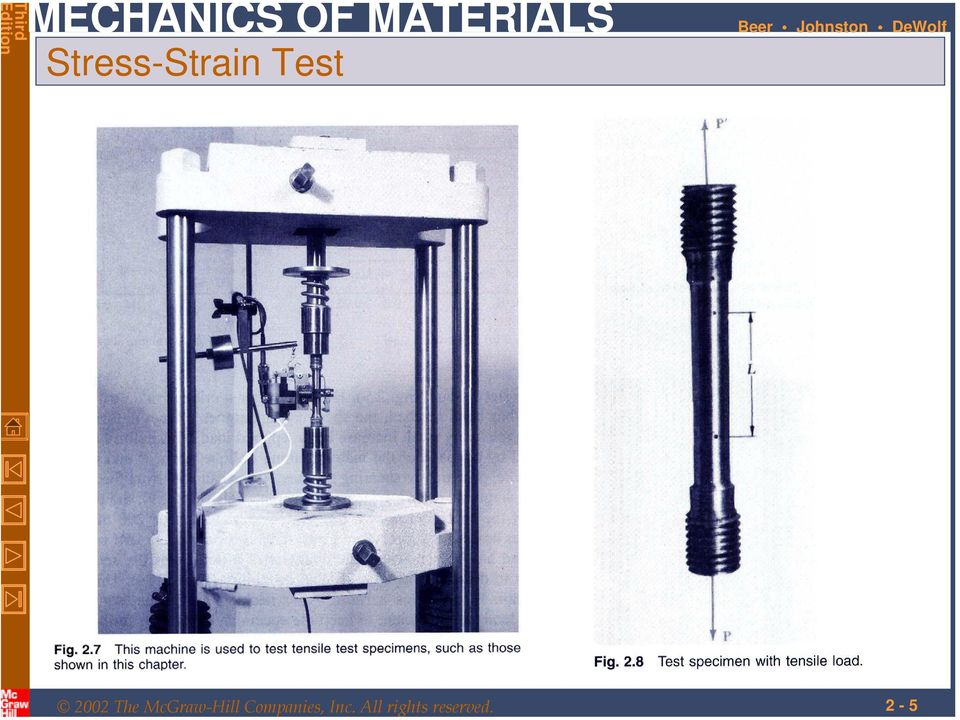
1 T dition CHTR MCHNICS OF MTRIS Ferdinand. Beer. Russell Johnston, Jr. John T. DeWolf ecture Notes: J. Walt Oler Texas Tech University Stress and Strain xial oading

2 - Contents Stress & Strain: xial oading Normal Strain Stress-Strain Test Stress-Strain Diagram: Ductile Materials Stress-Strain Diagram: Brittle Materials Hooke s aw: Modulus of lasticity lastic vs. lastic Behavior Fatigue Deformations Under xial oading xample.01 Sample roblem.1 Static Indeterminacy xample.04 Thermal Stresses oisson s Ratio Generalized Hooke s aw Dilatation: Bulk Modulus Shearing Strain xample. Relation mong, ν, and G Sample roblem.5 Composite Materials Saint-Venant s rinciple Stress Concentration: Hole Stress Concentration: Fillet xample.1 lastoplastic Materials lastic Deformations Residual Stresses xample.14,.15,.16

3 - Stress & Strain: xial oading Suitability of a structure or machine may depend on the deformations in the structure as well as the stresses induced under loading. Statics analyses alone are not sufficient. Considering structures as deformable allows determination of member forces and reactions which are statically indeterminate. Determination of the stress distribution within a member also requires consideration of deformations in the member. Chapter is concerned with deformation of a structural member under axial loading. ater chapters will deal with torsional and pure bending loads.

4 - 4 Normal Strain σ stress δ ε normal strain σ δ ε σ δ δ ε

5 - 5 Stress-Strain Test
6 - 6 Stress-Strain Diagram: Ductile Materials

7 - 7 Stress-Strain Diagram: Brittle Materials

8 - 8 Hooke s aw: Modulus of lasticity Below the yield stress σ ε Youngs Modulus or Modulus of lasticity Strength is affected by alloying, heat treating, and manufacturing process but stiffness (Modulus of lasticity) is not.

9 - 9 lastic vs. lastic Behavior If the strain disappears when the stress is removed, the material is said to behave elastically. The largest stress for which this occurs is called the elastic limit. When the strain does not return to zero after the stress is removed, the material is said to behave plastically.

10 - Fatigue Fatigue properties are shown on S-N diagrams. member may fail due to fatigue at stress levels significantly below the ultimate strength if subjected to many loading cycles. When the stress is reduced below the endurance limit, fatigue failures do not occur for any number of cycles.

11 - 11 Deformations Under xial oading From Hooke s aw: σ σ ε ε From the definition of strain: δ ε quating and solving for the deformation, δ With variations in loading, cross-section or material properties, i δ i i i i

12 - 1 xample psi D 1.07 in. d in. SOUTION: Divide the rod into components at the load application points. pply a free-body analysis on each component to determine the internal force Determine the deformation of the steel rod shown under the given loads. valuate the total of the component deflections.

13 - 1 SOUTION: Divide the rod into three components: pply free-body analysis to each component to determine internal forces, lb lb lb valuate total deflection, δ i i i i i ( 60 ) 1 ( 15 ) 1 ( 0 ) in in. 0.9 in 16 in. 0.in δ 75.9 in.
 1 ( 15 ) 1 ( 0 ) + + 0.9 0.9 0. in. 1 + + 16 1 1 1 in. 0.9 in 16 in.")
14 - 14 Sample roblem.1 SOUTION: The rigid bar BD is supported by two links B and CD. ink B is made of aluminum ( 70 Ga) and has a cross-sectional area of 500 mm. ink CD is made of steel ( 00 Ga) and has a cross-sectional area of (600 mm ). For the 0-kN force shown, determine the deflection a) of B, b) of D, and c) of. pply a free-body analysis to the bar BD to find the forces exerted by links B and DC. valuate the deformation of links B and DC or the displacements of B and D. Work out the geometry to find the deflection at given the deflections at B and D.
 of B, b) of D, and c) of.")
15 - 15 Sample roblem.1 SOUTION: Free body: Bar BD Displacement of B: δ B ( 60 N)( 0.m) -6 9 ( 500 m )( 70 a) m M F F B 0 M CD D 0 B 0 ( 0kN 0.6m) 0 ( 0kN 0.4m) + F + 90kN tension F CD B 60kN compression 0.m 0.m Displacement of D: δ D δ B mm ( 90 N)( 0.4m) -6 9 ( 600 m )( 00 a) 00 6 m δ D 0.00 mm
 0 ( 0kN 0.4m) + F + 90kN tension F CD B 60kN compression 0.m 0.")
16 - 16 Sample roblem.1 Displacement of D: BB DD BH HD mm 0.00 mm x 7.7 mm ( 00 mm) x x DD δ 0.00 mm δ H HD 1.98 mm ( ) mm 7.7 mm δ 1.98 mm
 x x DD δ 0.")
17 - 17 Static Indeterminacy Structures for which internal forces and reactions cannot be determined from statics alone are said to be statically indeterminate. structure will be statically indeterminate whenever it is held by more supports than are required to maintain its equilibrium. Redundant reactions are replaced with unknown loads which along with the other loads must produce compatible deformations. Deformations due to actual loads and redundant reactions are determined separately and then added or superposed. δ δ + δ R 0

18 - 18 xample.04 Determine the reactions at and B for the steel bar and loading shown, assuming a close fit at both supports before the loads are applied. SOUTION: Consider the reaction at B as redundant, release the bar from that support, and solve for the displacement at B due to the applied loads. Solve for the displacement at B due to the redundant reaction at B. Require that the displacements due to the loads and due to the redundant reaction be compatible, i.e., require that their sum be zero. Solve for the reaction at due to applied loads and the reaction found at B.

19 - 19 xample.04 SOUTION: Solve for the displacement at B due to the applied loads with the redundant constraint released, δ i i i i i m N m Solve for the displacement at B due to the redundant constraint, δ R 400 i R ii m i i B m ( 1.95 ) 50 R B 6 m N 6 m

20 - 0 xample.04 Require that the displacements due to the loads and due to the redundant reaction be compatible, δ δ + δ 1.15 δ R B R ( 1.95 ) N 577 kn R B 0 Find the reaction at due to the loads and the reaction at B F 0 R 00 kn 600kN kn R y kn R R B kn 577 kn
 N 577 kn R B 0 Find the reaction at due to the loads and the")
21 - 1 Thermal Stresses temperature change results in a change in length or thermal strain. There is no stress associated with the thermal strain unless the elongation is restrained by the supports. Treat the additional support as redundant and apply the principle of superposition. δ T α ( T ) α thermal expansion coef. δ δ α T + δ 0 ( T ) + 0 δ The thermal deformation and the deformation from the redundant support must be compatible. δ δt + δ 0 α( T ) σ α ( T )
22 - oisson s Ratio For a slender bar subjected to axial loading: σ ε x x σ y σ z 0 The elongation in the x-direction is accompanied by a contraction in the other directions. ssuming that the material is isotropic (no directional dependence), ε y ε z 0 oisson s ratio is defined as lateral strain ε y ν axial strain ε x ε z ε x
23 - Generalized Hooke s aw For an element subjected to multi-axial loading, the normal strain components resulting from the stress components may be determined from the principle of superposition. This requires: 1) strain is linearly related to stress ) deformations are small With these restrictions: ε ε ε x y z σ νσ x y νσ + z νσ σ x y νσ + z νσ νσ x y σ + z
24 Dilatation: Bulk Modulus Relative to the unstressed state, the change in volume is e 1 ( 1+ ε )( 1+ ε )( 1+ ε ) 1 1+ ε + ε + ε ε x 1 ν [ ] [ ] + ε y x + ε ( σ + σ + σ ) x z y y z dilatation (change in volume per unit volume) z For element subjected to uniform hydrostatic pressure, ( 1 ν ) p e p k 1 ( ν ) k bulk modulus Subjected to uniform pressure, dilatation must be negative, therefore 0 <ν < 1 x y z
25 - 5 Shearing Strain cubic element subjected to a shear stress will deform into a rhomboid. The corresponding shear strain is quantified in terms of the change in angle between the sides, τ xy ( ) f γ xy plot of shear stress vs. shear strain is similar the previous plots of normal stress vs. normal strain except that the strength values are approximately half. For small strains, τ Gγ τ Gγ τ Gγ xy xy yz yz where G is the modulus of rigidity or shear modulus. zx zx
26 - 6 xample. rectangular block of material with modulus of rigidity G 90 ksi is bonded to two rigid horizontal plates. The lower plate is fixed, while the upper plate is subjected to a horizontal force. Knowing that the upper plate moves through 0.04 in. under the action of the force, determine a) the average shearing strain in the material, and b) the force exerted on the plate. SOUTION: Determine the average angular deformation or shearing strain of the block. pply Hooke s law for shearing stress and strain to find the corresponding shearing stress. Use the definition of shearing stress to find the force.
27 - 7 Determine the average angular deformation or shearing strain of the block. γ xy 0.04in. tan γ xy γ xy 0.00 rad in. pply Hooke s law for shearing stress and strain to find the corresponding shearing stress. τ xy Gγ xy ( 90 psi)( 0.00 rad) 1800psi Use the definition of shearing stress to find the force. τ ( 1800 psi)( 8in. )(.5in. ) 6 lb xy 6.0kips
28 - 8 Relation mong, ν, and G n axially loaded slender bar will elongate in the axial direction and contract in the transverse directions. n initially cubic element oriented as in top figure will deform into a rectangular parallelepiped. The axial load produces a normal strain. If the cubic element is oriented as in the bottom figure, it will deform into a rhombus. xial load also results in a shear strain. Components of normal and shear strain are related, G ( 1+ν )
29 - 9 Sample roblem.5 circle of diameter d 9 in. is scribed on an unstressed aluminum plate of thickness t /4 in. Forces acting in the plane of the plate later cause normal stresses σ x 1 ksi and σ z 0 ksi. For x 6 psi and ν 1/, determine the change in: a) the length of diameter B, b) the length of diameter CD, c) the thickness of the plate, and d) the volume of the plate.
30 - 0 SOUTION: pply the generalized Hooke s aw to find the three components of normal strain. ε ε ε x y z σ + x 1 6 psi νσ x νσ x νσ y σ + y νσ νσ z ( 1ksi) 0 ( 0ksi) in./in. νσ z y in./in. σ + z in./in. 1 valuate the deformation components. δ B ε d ( in./in. )( 9in. ) x δ C ε d D t δ t ε y z δ B in. ( in./in. )( 9in. ) δ C D in. ( in./in. )( 0.75in. ) δ t Find the change in volume e ε V x + ε ev y + ε z V in /in in. ( ) in in
31 - 1 Composite Materials Fiber-reinforced composite materials are formed from lamina of fibers of graphite, glass, or polymers embedded in a resin matrix. Normal stresses and strains are related by Hooke s aw but with directionally dependent moduli of elasticity, x ν σ x ε xy x ε y ε x y ν σ ε xz y y ε z ε x z σ z ε Transverse contractions are related by directionally dependent values of oisson s ratio, e.g., Materials with directionally dependent mechanical properties are anisotropic. z
32 - Saint-Venant s rinciple oads transmitted through rigid plates result in uniform distribution of stress and strain. Concentrated loads result in large stresses in the vicinity of the load application point. Stress and strain distributions become uniform at a relatively short distance from the load application points. Saint-Venant s rinciple: Stress distribution may be assumed independent of the mode of load application except in the immediate vicinity of load application points.
33 - Stress Concentration: Hole Discontinuities of cross section may result in high localized or concentrated stresses. K σ σ max ave
34 - 4 Stress Concentration: Fillet
35 - 5 xample.1 SOUTION: Determine the largest axial load that can be safely supported by a flat steel bar consisting of two portions, both mm thick, and respectively 40 and 60 mm wide, connected by fillets of radius r 8 mm. ssume an allowable normal stress of 165 Ma. Determine the geometric ratios and find the stress concentration factor from Fig..64b. Find the allowable average normal stress using the material allowable normal stress and the stress concentration factor. pply the definition of normal stress to find the allowable load.
36 - 6 Determine the geometric ratios and find the stress concentration factor from Fig..64b. D d 60mm mm K 1.8 r d 8mm 40mm 0.0 Find the allowable average normal stress using the material allowable normal stress and the stress concentration factor. σ σ K 165 Ma 1.8 max ave 90.7 Ma pply the definition of normal stress to find the allowable load. σ ( 40mm)( mm)( 90.7 Ma) ave 6. N 6.kN
37 - 7 lastoplastic Materials revious analyses based on assumption of linear stress-strain relationship, i.e., stresses below the yield stress ssumption is good for brittle material which rupture without yielding If the yield stress of ductile materials is exceeded, then plastic deformations occur nalysis of plastic deformations is simplified by assuming an idealized elastoplastic material Deformations of an elastoplastic material are divided into elastic and plastic ranges ermanent deformations result from loading beyond the yield stress
38 - 8 lastic Deformations σ ave σ max K σ Y Y K lastic deformation while maximum stress is less than yield stress Maximum stress is equal to the yield stress at the maximum elastic loading U σ Y K Y t loadings above the maximum elastic load, a region of plastic deformations develop near the hole s the loading increases, the plastic region expands until the section is at a uniform stress equal to the yield stress
39 - 9 Residual Stresses When a single structural element is loaded uniformly beyond its yield stress and then unloaded, it is permanently deformed but all stresses disappear. This is not the general result. Residual stresses will remain in a structure after loading and unloading if - only part of the structure undergoes plastic deformation - different parts of the structure undergo different plastic deformations Residual stresses also result from the uneven heating or cooling of structures or structural elements
40 - 40 xample.14,.15,.16 cylindrical rod is placed inside a tube of the same length. The ends of the rod and tube are attached to a rigid support on one side and a rigid plate on the other. The load on the rod-tube assembly is increased from zero to 5.7 kips and decreased back to zero. a) draw a load-deflection diagram for the rod-tube assembly b) determine the maximum elongation c) determine the permanent set d) calculate the residual stresses in the rod and tube. σ r r Y, r 0.075in ksi psi σ t t Y, t 0.0in ksi psi
41 - 41 xample.14,.15,.16 a) draw a load-deflection diagram for the rodtube assembly Y, r σ Y, r r ( 6ksi)( 0.075in ).7 kips δ Y,r ε Y, r σ Y, r Y, r psi 0in. 6 psi - in. Y, t σ Y, t t ( 45ksi)( 0.0in ) 4.5 kips δ Y,t ε Y, t σ Y, t Y, t psi 0in. 90 psi - in. r + t δ δ δ r t
42 - 4 xample.14,.15,.16 b,c) determine the maximum elongation and permanent set at a load of 5.7 kips, the rod has reached the plastic range while the tube is still in the elastic range r t σ t Y, r t t.7 kips r ( 5.7.7).0 kips 0ksi 0.1in kips.0 kips δ t ε t σ t t psi 0in. psi δ max δ t 60 in. the rod-tube assembly unloads along a line parallel to 0Y r 4.5kips m 15kips in. slope - 6 in. δ m max 5.7 kips kips in. in. δ p δ max + δ ( ) in. δ p 14.4 in.
43 - 4 xample.14,.15,.16 calculate the residual stresses in the rod and tube. calculate the reverse stresses in the rod and tube caused by unloading and add them to the maximum stresses. δ ε in. in. 1.5 in. in. σ r σ t ε ε t r 6 ( 1.5 )( 0 psi) 6 ( 1.5 )( 15 psi) 45.6 ksi.8ksi σ σ residual, r residual, t σ + σ σ + σ t r t r ( ) ksi 9. 6ksi ( 0.8) ksi 7.ksi
P4 Stress and Strain Dr. A.B. Zavatsky MT07 Lecture 3 Statically Indeterminate Structures
 4 Stress and Strain Dr... Zavatsky MT07 ecture 3 Statically Indeterminate Structures Statically determinate structures. Statically indeterminate structures (equations of equilibrium, compatibility, and
Stress Strain Relationships
 Stress Strain Relationships Tensile Testing One basic ingredient in the study of the mechanics of deformable bodies is the resistive properties of materials. These properties relate the stresses to the
Solid Mechanics. Stress. What you ll learn: Motivation
 Solid Mechanics Stress What you ll learn: What is stress? Why stress is important? What are normal and shear stresses? What is strain? Hooke s law (relationship between stress and strain) Stress strain
Design Analysis and Review of Stresses at a Point
 Design Analysis and Review of Stresses at a Point Need for Design Analysis: To verify the design for safety of the structure and the users. To understand the results obtained in FEA, it is necessary to
STRESS AND DEFORMATION ANALYSIS OF LINEAR ELASTIC BARS IN TENSION
 Chapter 11 STRESS AND DEFORMATION ANALYSIS OF LINEAR ELASTIC BARS IN TENSION Figure 11.1: In Chapter10, the equilibrium, kinematic and constitutive equations for a general three-dimensional solid deformable
Objectives. Experimentally determine the yield strength, tensile strength, and modules of elasticity and ductility of given materials.
 Lab 3 Tension Test Objectives Concepts Background Experimental Procedure Report Requirements Discussion Objectives Experimentally determine the yield strength, tensile strength, and modules of elasticity
Chapter Outline. Mechanical Properties of Metals How do metals respond to external loads?
 Mechanical Properties of Metals How do metals respond to external loads? Stress and Strain Tension Compression Shear Torsion Elastic deformation Plastic Deformation Yield Strength Tensile Strength Ductility
The elements used in commercial codes can be classified in two basic categories:
 CHAPTER 3 Truss Element 3.1 Introduction The single most important concept in understanding FEA, is the basic understanding of various finite elements that we employ in an analysis. Elements are used for
Mechanical Properties - Stresses & Strains
 Mechanical Properties - Stresses & Strains Types of Deformation : Elasic Plastic Anelastic Elastic deformation is defined as instantaneous recoverable deformation Hooke's law : For tensile loading, σ =
Solution for Homework #1
 Solution for Homework #1 Chapter 2: Multiple Choice Questions (2.5, 2.6, 2.8, 2.11) 2.5 Which of the following bond types are classified as primary bonds (more than one)? (a) covalent bonding, (b) hydrogen
CH 6: Fatigue Failure Resulting from Variable Loading
 CH 6: Fatigue Failure Resulting from Variable Loading Some machine elements are subjected to static loads and for such elements static failure theories are used to predict failure (yielding or fracture).
8.2 Elastic Strain Energy
 Section 8. 8. Elastic Strain Energy The strain energy stored in an elastic material upon deformation is calculated below for a number of different geometries and loading conditions. These expressions for
Introduction to Mechanical Behavior of Biological Materials
 Introduction to Mechanical Behavior of Biological Materials Ozkaya and Nordin Chapter 7, pages 127-151 Chapter 8, pages 173-194 Outline Modes of loading Internal forces and moments Stiffness of a structure
Torsion Tests. Subjects of interest
 Chapter 10 Torsion Tests Subjects of interest Introduction/Objectives Mechanical properties in torsion Torsional stresses for large plastic strains Type of torsion failures Torsion test vs.tension test
Structural Axial, Shear and Bending Moments
 Structural Axial, Shear and Bending Moments Positive Internal Forces Acting Recall from mechanics of materials that the internal forces P (generic axial), V (shear) and M (moment) represent resultants
AN EXPLANATION OF JOINT DIAGRAMS
 AN EXPLANATION OF JOINT DIAGRAMS When bolted joints are subjected to external tensile loads, what forces and elastic deformation really exist? The majority of engineers in both the fastener manufacturing
Stress-Strain Material Laws
 5 Stress-Strain Material Laws 5 Lecture 5: STRSS-STRAIN MATRIAL LAWS TABL OF CONTNTS Page 5. Introduction..................... 5 3 5.2 Constitutive quations................. 5 3 5.2. Material Behavior
METU DEPARTMENT OF METALLURGICAL AND MATERIALS ENGINEERING
 METU DEPARTMENT OF METALLURGICAL AND MATERIALS ENGINEERING Met E 206 MATERIALS LABORATORY EXPERIMENT 1 Prof. Dr. Rıza GÜRBÜZ Res. Assist. Gül ÇEVİK (Room: B-306) INTRODUCTION TENSION TEST Mechanical testing
Unit 6 Plane Stress and Plane Strain
 Unit 6 Plane Stress and Plane Strain Readings: T & G 8, 9, 10, 11, 12, 14, 15, 16 Paul A. Lagace, Ph.D. Professor of Aeronautics & Astronautics and Engineering Systems There are many structural configurations
Mechanical Properties of Metals Mechanical Properties refers to the behavior of material when external forces are applied
 Mechanical Properties of Metals Mechanical Properties refers to the behavior of material when external forces are applied Stress and strain fracture or engineering point of view: allows to predict the
EDEXCEL NATIONAL CERTIFICATE/DIPLOMA MECHANICAL PRINCIPLES AND APPLICATIONS NQF LEVEL 3 OUTCOME 1 - LOADING SYSTEMS TUTORIAL 3 LOADED COMPONENTS
 EDEXCEL NATIONAL CERTIICATE/DIPLOMA MECHANICAL PRINCIPLES AND APPLICATIONS NQ LEVEL 3 OUTCOME 1 - LOADING SYSTEMS TUTORIAL 3 LOADED COMPONENTS 1. Be able to determine the effects of loading in static engineering
MATERIALS AND MECHANICS OF BENDING
 HAPTER Reinforced oncrete Design Fifth Edition MATERIALS AND MEHANIS OF BENDING A. J. lark School of Engineering Department of ivil and Environmental Engineering Part I oncrete Design and Analysis b FALL
Design of reinforced concrete columns. Type of columns. Failure of reinforced concrete columns. Short column. Long column
 Design of reinforced concrete columns Type of columns Failure of reinforced concrete columns Short column Column fails in concrete crushed and bursting. Outward pressure break horizontal ties and bend
Module 2. Analysis of Statically Indeterminate Structures by the Matrix Force Method. Version 2 CE IIT, Kharagpur
 Module Analysis of Statically Indeterminate Structures by the Matrix Force Method esson 11 The Force Method of Analysis: Frames Instructional Objectives After reading this chapter the student will be able
Activity 2.3b Engineering Problem Solving Answer Key
 Activity.3b Engineering roblem Solving Answer Key 1. A force of 00 lbs pushes against a rectangular plate that is 1 ft. by ft. Determine the lb lb pressure in and that the plate exerts on the ground due
Statics of Structural Supports
 Statics of Structural Supports TYPES OF FORCES External Forces actions of other bodies on the structure under consideration. Internal Forces forces and couples exerted on a member or portion of the structure
REVIEW PROBLEMS & SOLUTIONS JAMES M. GERE BARRY J. GOODNO
 REVIEW ROEMS & SOUTIONS JMES M. GERE RRY J. GOODNO ppendix FE Exam Review roblems R-1.1: plane truss has downward applied load at joint and another load applied leftward at joint 5. The force in member
Fatigue Performance Evaluation of Forged Steel versus Ductile Cast Iron Crankshaft: A Comparative Study (EXECUTIVE SUMMARY)
") Fatigue Performance Evaluation of Forged Steel versus Ductile Cast Iron Crankshaft: A Comparative Study (EXECUTIVE SUMMARY) Ali Fatemi, Jonathan Williams and Farzin Montazersadgh Professor and Graduate
Fatigue Performance Evaluation of Forged Steel versus Ductile Cast Iron Crankshaft: A Comparative Study (EXECUTIVE SUMMARY) Ali Fatemi, Jonathan Williams and Farzin Montazersadgh Professor and Graduate
σ y ( ε f, σ f ) ( ε f
 ( ε f") Typical stress-strain curves for mild steel and aluminum alloy from tensile tests L L( 1 + ε) A = --- A u u 0 1 E l mild steel fracture u ( ε f, f ) ( ε f, f ) ε 0 ε 0.2 = 0.002 aluminum alloy fracture
Typical stress-strain curves for mild steel and aluminum alloy from tensile tests L L( 1 + ε) A = --- A u u 0 1 E l mild steel fracture u ( ε f, f ) ( ε f, f ) ε 0 ε 0.2 = 0.002 aluminum alloy fracture
Optimum proportions for the design of suspension bridge
 Journal of Civil Engineering (IEB), 34 (1) (26) 1-14 Optimum proportions for the design of suspension bridge Tanvir Manzur and Alamgir Habib Department of Civil Engineering Bangladesh University of Engineering
EDEXCEL NATIONAL CERTIFICATE/DIPLOMA MECHANICAL PRINCIPLES OUTCOME 2 ENGINEERING COMPONENTS TUTORIAL 1 STRUCTURAL MEMBERS
 ENGINEERING COMPONENTS EDEXCEL NATIONAL CERTIFICATE/DIPLOMA MECHANICAL PRINCIPLES OUTCOME ENGINEERING COMPONENTS TUTORIAL 1 STRUCTURAL MEMBERS Structural members: struts and ties; direct stress and strain,
Mechanics of Materials Summary
 Mechanics of Materials Summary 1. Stresses and Strains 1.1 Normal Stress Let s consider a fixed rod. This rod has length L. Its cross-sectional shape is constant and has area. Figure 1.1: rod with a normal
Problem 1: Computation of Reactions. Problem 2: Computation of Reactions. Problem 3: Computation of Reactions
 Problem 1: Computation of Reactions Problem 2: Computation of Reactions Problem 3: Computation of Reactions Problem 4: Computation of forces and moments Problem 5: Bending Moment and Shear force Problem
MCE380: Measurements and Instrumentation Lab. Chapter 9: Force, Torque and Strain Measurements
 MCE380: Measurements and Instrumentation Lab Chapter 9: Force, Torque and Strain Measurements Topics: Elastic Elements for Force Measurement Dynamometers and Brakes Resistance Strain Gages Holman, Ch.
Stresses in Beam (Basic Topics)
") Chapter 5 Stresses in Beam (Basic Topics) 5.1 Introduction Beam : loads acting transversely to the longitudinal axis the loads create shear forces and bending moments, stresses and strains due to V and
Chapter 5 Stresses in Beam (Basic Topics) 5.1 Introduction Beam : loads acting transversely to the longitudinal axis the loads create shear forces and bending moments, stresses and strains due to V and
Mechanics of Materials. Chapter 4 Shear and Moment In Beams
 Mechanics of Materials Chapter 4 Shear and Moment In Beams 4.1 Introduction The term beam refers to a slender bar that carries transverse loading; that is, the applied force are perpendicular to the bar.
Structural Integrity Analysis
 Structural Integrity Analysis 1. STRESS CONCENTRATION Igor Kokcharov 1.1 STRESSES AND CONCENTRATORS 1.1.1 Stress An applied external force F causes inner forces in the carrying structure. Inner forces
Multiaxial Fatigue. Professor Darrell Socie. 2008-2014 Darrell Socie, All Rights Reserved
 Multiaxial Fatigue Professor Darrell Socie 2008-2014 Darrell Socie, All Rights Reserved Outline Stresses around holes Crack Nucleation Crack Growth MultiaxialFatigue 2008-2014 Darrell Socie, All Rights
Lecture 12: Fundamental Concepts in Structural Plasticity
 Lecture 12: Fundamental Concepts in Structural Plasticity Plastic properties of the material were already introduced briefly earlier in the present notes. The critical slenderness ratio of column is controlled
Nonlinear analysis and form-finding in GSA Training Course
 Nonlinear analysis and form-finding in GSA Training Course Non-linear analysis and form-finding in GSA 1 of 47 Oasys Ltd Non-linear analysis and form-finding in GSA 2 of 47 Using the GSA GsRelax Solver
Analysis of Stresses and Strains
 Chapter 7 Analysis of Stresses and Strains 7.1 Introduction axial load = P / A torsional load in circular shaft = T / I p bending moment and shear force in beam = M y / I = V Q / I b in this chapter, we
Thermal Stress & Strain. 07 Thermal Stress and Strain Copyright G G Schierle, 2001-05 press Esc to end, for next, for previous slide 3
 Thermal Stress & Strain 07 Thermal Stress and Strain Copyright G G Schierle, 2001-05 press Esc to end, for next, for previous slide 3 Thermal Stress & Strain 07 Thermal Stress and Strain Copyright G G
CEEN 162 - Geotechnical Engineering Laboratory Session 7 - Direct Shear and Unconfined Compression Tests
 PURPOSE: The parameters of the shear strength relationship provide a means of evaluating the load carrying capacity of soils, stability of slopes, and pile capacity. The direct shear test is one of the
Deflections. Question: What are Structural Deflections?
 Question: What are Structural Deflections? Answer: The deformations or movements of a structure and its components, such as beams and trusses, from their original positions. It is as important for the
Fatigue. 3. Final fracture (rough zone) 1. Fatigue origin. 2. Beach marks (velvety zone)
 1. Fatigue origin. 2. Beach marks (velvety zone)") Fatigue Term fatigue introduced by Poncelet (France) 1839 progressive fracture is more descriptive 1. Minute crack at critical area of high local stress (geometric stress raiser, flaws, preexisting cracks)
Fatigue Term fatigue introduced by Poncelet (France) 1839 progressive fracture is more descriptive 1. Minute crack at critical area of high local stress (geometric stress raiser, flaws, preexisting cracks)
NOTCHES AND THEIR EFFECTS. Ali Fatemi - University of Toledo All Rights Reserved Chapter 7 Notches and Their Effects 1
 NOTCHES AND THEIR EFFECTS Ali Fatemi - University of Toledo All Rights Reserved Chapter 7 Notches and Their Effects 1 CHAPTER OUTLINE Background Stress/Strain Concentrations S-N Approach for Notched Members
Nonlinear Analysis Using Femap with NX Nastran
 Nonlinear Analysis Using Femap with NX Nastran Chip Fricke, Principal Applications Engineer, Agenda Nonlinear Analysis Using Femap with NX Nastran Who am I? Overview of Nonlinear Analysis Comparison of
Chapter 5 Bridge Deck Slabs. Bridge Engineering 1
 Chapter 5 Bridge Deck Slabs Bridge Engineering 1 Basic types of bridge decks In-situ reinforced concrete deck- (most common type) Pre-cast concrete deck (minimize the use of local labor) Open steel grid
ENGINEERING COUNCIL CERTIFICATE LEVEL
 ENGINEERING COUNCIL CERTIICATE LEVEL ENGINEERING SCIENCE C103 TUTORIAL - BASIC STUDIES O STRESS AND STRAIN You should judge your progress by completing the self assessment exercises. These may be sent
Tensile Testing Laboratory
 Tensile Testing Laboratory By Stephan Favilla 0723668 ME 354 AC Date of Lab Report Submission: February 11 th 2010 Date of Lab Exercise: January 28 th 2010 1 Executive Summary Tensile tests are fundamental
SEISMIC DESIGN. Various building codes consider the following categories for the analysis and design for earthquake loading:
 SEISMIC DESIGN Various building codes consider the following categories for the analysis and design for earthquake loading: 1. Seismic Performance Category (SPC), varies from A to E, depending on how the
ME 343: Mechanical Design-3
 ME 343: Mechanical Design-3 Design of Shaft (continue) Dr. Aly Mousaad Aly Department of Mechanical Engineering Faculty of Engineering, Alexandria University Objectives At the end of this lesson, we should
Tensile Testing of Steel
 C 265 Lab No. 2: Tensile Testing of Steel See web for typical report format including: TITL PAG, ABSTRACT, TABL OF CONTNTS, LIST OF TABL, LIST OF FIGURS 1.0 - INTRODUCTION See General Lab Report Format
2.75 6.525 Problem Set 1 Solutions to ME problems Fall 2013
 2.75 6.525 Problem Set 1 Solutions to ME problems Fall 2013 2. Pinned Joint problem Jacob Bayless a) Draw a free-body diagram for the pin. How is it loaded? Does the loading depend on whether the pin is
Shear Forces and Bending Moments
 Chapter 4 Shear Forces and Bending Moments 4.1 Introduction Consider a beam subjected to transverse loads as shown in figure, the deflections occur in the plane same as the loading plane, is called the
Section 16: Neutral Axis and Parallel Axis Theorem 16-1
 Section 16: Neutral Axis and Parallel Axis Theorem 16-1 Geometry of deformation We will consider the deformation of an ideal, isotropic prismatic beam the cross section is symmetric about y-axis All parts
PROPERTIES OF MATERIALS
 1 PROPERTIES OF MATERIALS 1.1 PROPERTIES OF MATERIALS Different materials possess different properties in varying degree and therefore behave in different ways under given conditions. These properties
different levels, also called repeated, alternating, or fluctuating stresses.
 Fatigue and Dynamic Loading 1 Fti Fatigue fil failure: 2 Static ti conditions : loads are applied gradually, to give sufficient i time for the strain to fully develop. Variable conditions : stresses vary
Technology of EHIS (stamping) applied to the automotive parts production
 applied to the automotive parts production") Laboratory of Applied Mathematics and Mechanics Technology of EHIS (stamping) applied to the automotive parts production Churilova Maria, Saint-Petersburg State Polytechnical University Department of Applied
Laboratory of Applied Mathematics and Mechanics Technology of EHIS (stamping) applied to the automotive parts production Churilova Maria, Saint-Petersburg State Polytechnical University Department of Applied
MECHANICAL PRINCIPLES HNC/D PRELIMINARY LEVEL TUTORIAL 1 BASIC STUDIES OF STRESS AND STRAIN
 MECHANICAL PRINCIPLES HNC/D PRELIMINARY LEVEL TUTORIAL 1 BASIC STUDIES O STRESS AND STRAIN This tutorial is essential for anyone studying the group of tutorials on beams. Essential pre-requisite knowledge
MECHANICS OF SOLIDS - BEAMS TUTORIAL TUTORIAL 4 - COMPLEMENTARY SHEAR STRESS
 MECHANICS OF SOLIDS - BEAMS TUTORIAL TUTORIAL 4 - COMPLEMENTARY SHEAR STRESS This the fourth and final tutorial on bending of beams. You should judge our progress b completing the self assessment exercises.
Type of Force 1 Axial (tension / compression) Shear. 3 Bending 4 Torsion 5 Images 6 Symbol (+ -)
 Shear. 3 Bending 4 Torsion 5 Images 6 Symbol (+ -)") Cause: external force P Force vs. Stress Effect: internal stress f 05 Force vs. Stress Copyright G G Schierle, 2001-05 press Esc to end, for next, for previous slide 1 Type of Force 1 Axial (tension /
Cause: external force P Force vs. Stress Effect: internal stress f 05 Force vs. Stress Copyright G G Schierle, 2001-05 press Esc to end, for next, for previous slide 1 Type of Force 1 Axial (tension /
BUCKLING OF BARS, PLATES, AND SHELLS. Virginia Polytechnic Institute and State University Biacksburg, Virginia 24061-0219
 BUCKLING OF BARS, PLATES, AND SHELLS ROBERT M. JONES Science and Mechanics Professor Emeritus of Engineering Virginia Polytechnic Institute and State University Biacksburg, Virginia 24061-0219 Bull Ridge
Finite Element Formulation for Beams - Handout 2 -
 Finite Element Formulation for Beams - Handout 2 - Dr Fehmi Cirak (fc286@) Completed Version Review of Euler-Bernoulli Beam Physical beam model midline Beam domain in three-dimensions Midline, also called
Sheet metal operations - Bending and related processes
 Sheet metal operations - Bending and related processes R. Chandramouli Associate Dean-Research SASTRA University, Thanjavur-613 401 Table of Contents 1.Quiz-Key... Error! Bookmark not defined. 1.Bending
INTRODUCTION TO BEAMS
 CHAPTER Structural Steel Design LRFD Method INTRODUCTION TO BEAMS Third Edition A. J. Clark School of Engineering Department of Civil and Environmental Engineering Part II Structural Steel Design and Analysis
Uniaxial Tension and Compression Testing of Materials. Nikita Khlystov Daniel Lizardo Keisuke Matsushita Jennie Zheng
 Uniaxial Tension and Compression Testing of Materials Nikita Khlystov Daniel Lizardo Keisuke Matsushita Jennie Zheng 3.032 Lab Report September 25, 2013 I. Introduction Understanding material mechanics
SLAB DESIGN. Introduction ACI318 Code provides two design procedures for slab systems:
 Reading Assignment SLAB DESIGN Chapter 9 of Text and, Chapter 13 of ACI318-02 Introduction ACI318 Code provides two design procedures for slab systems: 13.6.1 Direct Design Method (DDM) For slab systems
BEAMS: SHEAR AND MOMENT DIAGRAMS (GRAPHICAL)
") LECTURE Third Edition BES: SHER ND OENT DIGRS (GRPHICL). J. Clark School of Engineering Department of Civil and Environmental Engineering 3 Chapter 5.3 by Dr. Ibrahim. ssakkaf SPRING 003 ENES 0 echanics
LECTURE Third Edition BES: SHER ND OENT DIGRS (GRPHICL). J. Clark School of Engineering Department of Civil and Environmental Engineering 3 Chapter 5.3 by Dr. Ibrahim. ssakkaf SPRING 003 ENES 0 echanics
SHAFTS: TORSION LOADING AND DEFORMATION
 ECURE hird Edition SHAFS: ORSION OADING AND DEFORMAION A. J. Clark Shool of Engineering Department of Civil and Environmental Engineering 6 Chapter 3.1-3.5 by Dr. Ibrahim A. Assakkaf SPRING 2003 ENES 220
New approaches in Eurocode 3 efficient global structural design
 New approaches in Eurocode 3 efficient global structural design Part 1: 3D model based analysis using general beam-column FEM Ferenc Papp* and József Szalai ** * Associate Professor, Department of Structural
Introduction to Solid Modeling Using SolidWorks 2012 SolidWorks Simulation Tutorial Page 1
 Introduction to Solid Modeling Using SolidWorks 2012 SolidWorks Simulation Tutorial Page 1 In this tutorial, we will use the SolidWorks Simulation finite element analysis (FEA) program to analyze the response
MECHANICS OF SOLIDS - BEAMS TUTORIAL 1 STRESSES IN BEAMS DUE TO BENDING. On completion of this tutorial you should be able to do the following.
 MECHANICS OF SOLIDS - BEAMS TUTOIAL 1 STESSES IN BEAMS DUE TO BENDING This is the first tutorial on bending of beams designed for anyone wishing to study it at a fairly advanced level. You should judge
B.TECH. (AEROSPACE ENGINEERING) PROGRAMME (BTAE) Term-End Examination December, 2011 BAS-010 : MACHINE DESIGN
 PROGRAMME (BTAE) Term-End Examination December, 2011 BAS-010 : MACHINE DESIGN") No. of Printed Pages : 7 BAS-01.0 B.TECH. (AEROSPACE ENGINEERING) PROGRAMME (BTAE) CV CA CV C:) O Term-End Examination December, 2011 BAS-010 : MACHINE DESIGN Time : 3 hours Maximum Marks : 70 Note : (1)
No. of Printed Pages : 7 BAS-01.0 B.TECH. (AEROSPACE ENGINEERING) PROGRAMME (BTAE) CV CA CV C:) O Term-End Examination December, 2011 BAS-010 : MACHINE DESIGN Time : 3 hours Maximum Marks : 70 Note : (1)
(Seattle is home of Boeing Jets)
") Dr. Faeq M. Shaikh Seattle, Washington, USA (Seattle is home of Boeing Jets) 1 Pre Requisites for Today s Seminar Basic understanding of Finite Element Analysis Working Knowledge of Laminate Plate Theory
Dr. Faeq M. Shaikh Seattle, Washington, USA (Seattle is home of Boeing Jets) 1 Pre Requisites for Today s Seminar Basic understanding of Finite Element Analysis Working Knowledge of Laminate Plate Theory
Lab for Deflection and Moment of Inertia
 Deflection and Moment of Inertia Subject Area(s) Associated Unit Lesson Title Physics Wind Effects on Model Building Lab for Deflection and Moment of Inertia Grade Level (11-12) Part # 2 of 3 Lesson #
bi directional loading). Prototype ten story
. Prototype ten story") NEESR SG: Behavior, Analysis and Design of Complex Wall Systems The laboratory testing presented here was conducted as part of a larger effort that employed laboratory testing and numerical simulation
NEESR SG: Behavior, Analysis and Design of Complex Wall Systems The laboratory testing presented here was conducted as part of a larger effort that employed laboratory testing and numerical simulation
Approximate Analysis of Statically Indeterminate Structures
 Approximate Analysis of Statically Indeterminate Structures Every successful structure must be capable of reaching stable equilibrium under its applied loads, regardless of structural behavior. Exact analysis
Unit 3 (Review of) Language of Stress/Strain Analysis
 Language of Stress/Strain Analysis") Unit 3 (Review of) Language of Stress/Strain Analysis Readings: B, M, P A.2, A.3, A.6 Rivello 2.1, 2.2 T & G Ch. 1 (especially 1.7) Paul A. Lagace, Ph.D. Professor of Aeronautics & Astronautics and Engineering
Unit 3 (Review of) Language of Stress/Strain Analysis Readings: B, M, P A.2, A.3, A.6 Rivello 2.1, 2.2 T & G Ch. 1 (especially 1.7) Paul A. Lagace, Ph.D. Professor of Aeronautics & Astronautics and Engineering
CHAPTER 7 DISLOCATIONS AND STRENGTHENING MECHANISMS PROBLEM SOLUTIONS
 7-1 CHAPTER 7 DISLOCATIONS AND STRENGTHENING MECHANISMS PROBLEM SOLUTIONS Basic Concepts of Dislocations Characteristics of Dislocations 7.1 The dislocation density is just the total dislocation length
Long term performance of polymers
 1.0 Introduction Long term performance of polymers Polymer materials exhibit time dependent behavior. The stress and strain induced when a load is applied are a function of time. In the most general form
CRITERIA FOR PRELOADED BOLTS
 National Aeronautics and Space Administration Lyndon B. Johnson Space Center Houston, Texas 77058 REVISION A JULY 6, 1998 REPLACES BASELINE SPACE SHUTTLE CRITERIA FOR PRELOADED BOLTS CONTENTS 1.0 INTRODUCTION..............................................
Bending Stress in Beams
 936-73-600 Bending Stress in Beams Derive a relationship for bending stress in a beam: Basic Assumptions:. Deflections are very small with respect to the depth of the beam. Plane sections before bending
R&DE (Engineers), DRDO. Theories of Failure. rd_mech@yahoo.co.in. Ramadas Chennamsetti
, DRDO. Theories of Failure. rd_mech@yahoo.co.in. Ramadas Chennamsetti") heories of Failure ummary Maximum rincial stress theory Maximum rincial strain theory Maximum strain energy theory Distortion energy theory Maximum shear stress theory Octahedral stress theory Introduction
heories of Failure ummary Maximum rincial stress theory Maximum rincial strain theory Maximum strain energy theory Distortion energy theory Maximum shear stress theory Octahedral stress theory Introduction
ENGINEERING SCIENCE H1 OUTCOME 1 - TUTORIAL 3 BENDING MOMENTS EDEXCEL HNC/D ENGINEERING SCIENCE LEVEL 4 H1 FORMERLY UNIT 21718P
 ENGINEERING SCIENCE H1 OUTCOME 1 - TUTORIAL 3 BENDING MOMENTS EDEXCEL HNC/D ENGINEERING SCIENCE LEVEL 4 H1 FORMERLY UNIT 21718P This material is duplicated in the Mechanical Principles module H2 and those
Design of Steel Structures Prof. S.R.Satish Kumar and Prof. A.R.Santha Kumar
 Problem 1 Design a hand operated overhead crane, which is provided in a shed, whose details are: Capacity of crane = 50 kn Longitudinal spacing of column = 6m Center to center distance of gantry girder
Design MEMO 54a Reinforcement design for RVK 41
 Page of 5 CONTENTS PART BASIC ASSUMTIONS... 2 GENERAL... 2 STANDARDS... 2 QUALITIES... 3 DIMENSIONS... 3 LOADS... 3 PART 2 REINFORCEMENT... 4 EQUILIBRIUM... 4 Page 2 of 5 PART BASIC ASSUMTIONS GENERAL
Structural Analysis - II Prof. P. Banerjee Department of Civil Engineering Indian Institute of Technology, Bombay. Lecture - 02
 Structural Analysis - II Prof. P. Banerjee Department of Civil Engineering Indian Institute of Technology, Bombay Lecture - 02 Good morning. Today is the second lecture in the series of lectures on structural
4.2 Free Body Diagrams
 CE297-FA09-Ch4 Page 1 Friday, September 18, 2009 12:11 AM Chapter 4: Equilibrium of Rigid Bodies A (rigid) body is said to in equilibrium if the vector sum of ALL forces and all their moments taken about
Numerical Analysis of Independent Wire Strand Core (IWSC) Wire Rope
 Wire Rope") Numerical Analysis of Independent Wire Strand Core (IWSC) Wire Rope Rakesh Sidharthan 1 Gnanavel B K 2 Assistant professor Mechanical, Department Professor, Mechanical Department, Gojan engineering college,
Numerical Analysis of Independent Wire Strand Core (IWSC) Wire Rope Rakesh Sidharthan 1 Gnanavel B K 2 Assistant professor Mechanical, Department Professor, Mechanical Department, Gojan engineering college,
MECHANICS OF SOLIDS - BEAMS TUTORIAL 2 SHEAR FORCE AND BENDING MOMENTS IN BEAMS
 MECHANICS OF SOLIDS - BEAMS TUTORIAL 2 SHEAR FORCE AND BENDING MOMENTS IN BEAMS This is the second tutorial on bending of beams. You should judge your progress by completing the self assessment exercises.
Bending, Forming and Flexing Printed Circuits
 Bending, Forming and Flexing Printed Circuits John Coonrod Rogers Corporation Introduction: In the printed circuit board industry there are generally two main types of circuit boards; there are rigid printed
4.3 Results... 27 4.3.1 Drained Conditions... 27 4.3.2 Undrained Conditions... 28 4.4 References... 30 4.5 Data Files... 30 5 Undrained Analysis of
 Table of Contents 1 One Dimensional Compression of a Finite Layer... 3 1.1 Problem Description... 3 1.1.1 Uniform Mesh... 3 1.1.2 Graded Mesh... 5 1.2 Analytical Solution... 6 1.3 Results... 6 1.3.1 Uniform
COMPLEX STRESS TUTORIAL 3 COMPLEX STRESS AND STRAIN
 COMPLX STRSS TUTORIAL COMPLX STRSS AND STRAIN This tutorial is not part of the decel unit mechanical Principles but covers elements of the following sllabi. o Parts of the ngineering Council eam subject
Design Project 2. Sizing of a Bicycle Chain Ring Bolt Set. Statics and Mechanics of Materials I. ENGR 0135 Section 1040.
 Design Project 2 Sizing of a Bicycle Chain Ring Bolt Set Statics and Mechanics of Materials I ENGR 0135 Section 1040 November 9, 2014 Derek Nichols Michael Scandrol Mark Vavithes Nichols, Scandrol, Vavithes
CLASSICAL STRUCTURAL ANALYSIS
 Table of Contents CASSCA STRUCTURA ANAYSS... Conjugate beam method... External work and internal work... 3 Method of virtual force (unit load method)... 5 Castigliano s second theorem... Method of consistent
Fluid Mechanics: Static s Kinematics Dynamics Fluid
 Fluid Mechanics: Fluid mechanics may be defined as that branch of engineering science that deals with the behavior of fluid under the condition of rest and motion Fluid mechanics may be divided into three
Lap Fillet Weld Calculations and FEA Techniques
 Lap Fillet Weld Calculations and FEA Techniques By: MS.ME Ahmad A. Abbas Sr. Analysis Engineer Ahmad.Abbas@AdvancedCAE.com www.advancedcae.com Sunday, July 11, 2010 Advanced CAE All contents Copyright
TIE-31: Mechanical and thermal properties of optical glass
 PAGE 1/10 1 Density The density of optical glass varies from 239 for N-BK10 to 603 for SF66 In most cases glasses with higher densities also have higher refractive indices (eg SF type glasses) The density