Installation instructions, accessories - Navigation system, RTI
|
|
|
- Leslie Ellis
- 7 years ago
- Views:
Transcription
1 XC90 Section Group Weight(Kg/Pounds) Year Month / Page 1 of 20

2 Required tools A IMG IMG IMG IMG R R Page 2 of 20

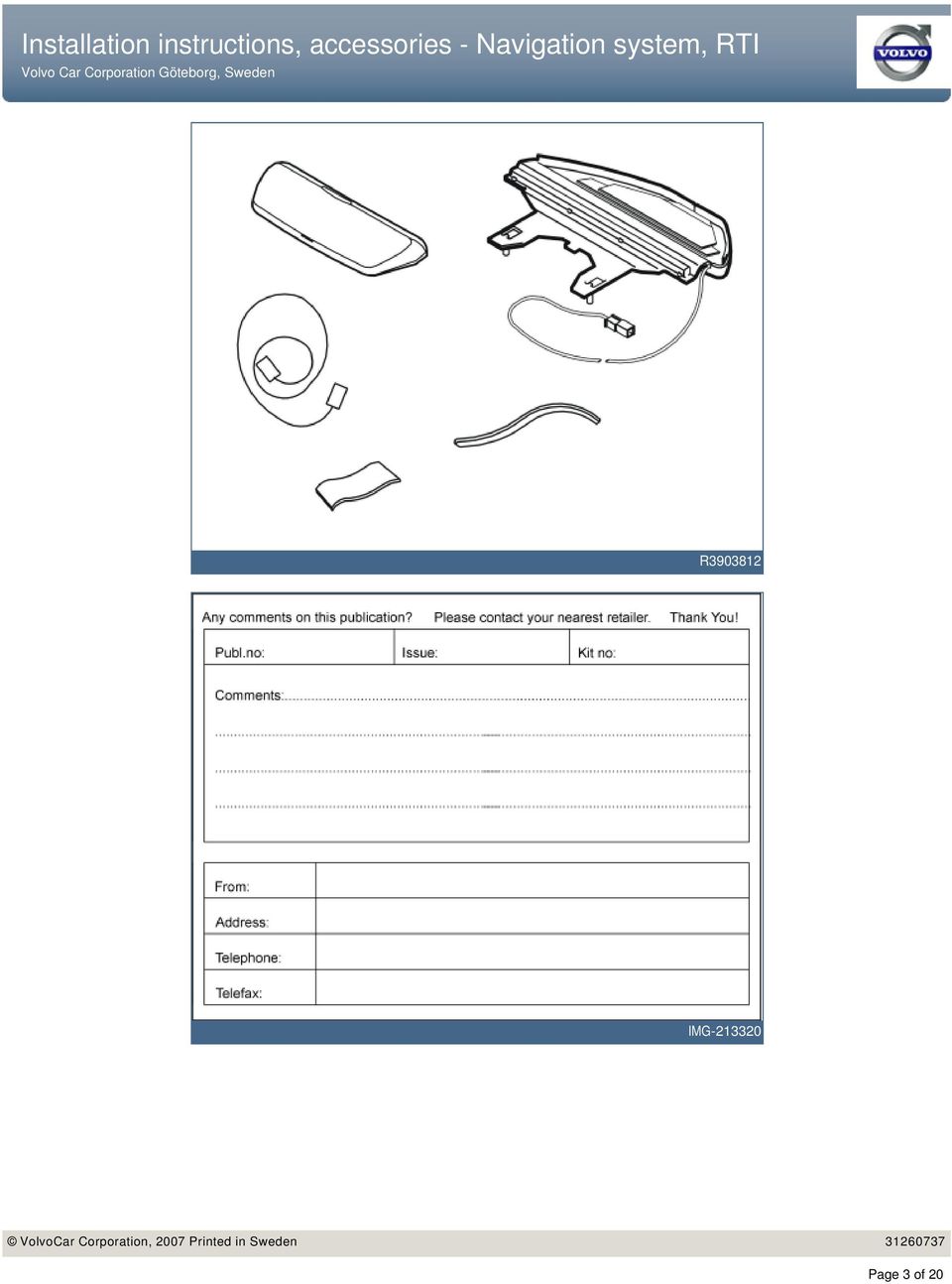
3 R IMG Page 3 of 20
4 INTRODUCTION Cars equipped with SRS/SIPS (Airbag) NOTE! Read through the entire text before carrying out any work. The front page gives the date of this edition and the edition it replaces The second page shows the tools needed for the installation and the contents of the installation kit Warning! Extra care must be taken when working on cars equipped with SRS/SIPS air bags. This is important to prevent: 1. Personal injury 2. Damage to or malfunction of the SRS/SIPS system. The illustrations display the procedure in order of operation. The order of operation is repeated in the text section Work on the SRS/SIPS systems or related components must always be carried out by an authorised Volvo workshop. Cut out the text page in order to follow the illustrations and text at the same time. Is the car equipped with SRS (supplemental restraint system)? Cars equipped with a driver's airbag have the letters "SRS" imprinted on the centre panel of the steering wheel. Cars equipped with driver's and passenger airbags are marked with "SRS" on both the steering wheel centre panel and also on the dashboard close to the airbag. If the car is equipped with SIPS (side impact protection system ) a "SIPS" decal is marked on both the front seats. Cars equipped with inflatable curtains have the marking "SRS" on one of the panels along the posts on the inside of the car. Cars equipped with SRS (supplemental restraint system) also have a "SRS" decal on the front windscreen. Do not damage the SRS wiring! Do not trap, fray, pierce or damage the SRS wiring. SRS wiring has orange casing and/or is plaited. Steering and front suspension The contact reel in the SRS system can easily be damaged when working on the steering wheel, steering shaft or steering gear. Refer to the SRS (supplemental restraint system) Service Manual or service instructions in VIDA for information on carrying out such work. This is to prevent damage. SRS warning lamp If the SRS warning lamp lights after repairs have been carried out, take the car to an authorised Volvo workshop. SRS collision sensor control module S60 / V70 (00-) / S80 / XC90 The collision sensor control module is located on the transmission tunnel Page 4 of 20

5 in the centre console, in front of the parking brake. WARNING! The air bag inflation areas must not be obstructed. Never place any objects, such as upholstery or accessories, within these areas. The panels must be able to deploy in the correct manner at the right time otherwise there is a risk of personal injury in the event of a collision. WARNING! The ignition must be in position "0" and the key removed from the ignition if any connector in the SRS system is to be disassembled. Then wait at least one minute. Then disconnect the battery negative lead before disassembling any of the connectors. When work is completed the ignition key must be turned to position "II" before reconnecting the battery negative lead. Navigation system, RTI This accessory requires software unique to the car. For European users, the TMC unit, part number , can be purchased separately. Page 5 of 20


6 1 Preparations Download the software for the accessory's function following the service information in VIDA. The software must be loaded before installing the accessory. IMG Preparations Place the driver's seat in its rearmost position. Turn the ignition switch to position 0. Disconnect the battery negative lead IMG Wait at least three minutes before unplugging the connectors or removing other electrical equipment. 3A Preparations Illustration A Remove the loudspeaker grille as follows: Take a piece of welding rodø 1.5 mm (1/16"). Bend it 90 at one end, L=5 mm (13/64"). The other end is bent to create a handle. First insert the bent end in the joint between the loudspeaker grille and the dashboard approximately as illustrated, until it engages. 3B R Turn the welding rod 90 so that the bent section catches the underneath of the loudspeaker grille. The welding rod may need moving along the joint to be turned. Illustration B Pull upwards until the loudspeaker grille detaches, it is securely fastened by four clips. R Do not damage the dashboard. Page 6 of 20
. Bend it 90 at one end, L=5 mm (13/64\"). The other end is bent to create a handle.")

7 3C Place the loudspeaker grille to one side. Illustration C Applies to cars without centre loudspeakers Remove the bracket for the loudspeaker grille by removing the five screws and pulling the grille up from the dashboard. Illustration D 3D R Applies to cars with a centrally mounted loudspeaker Remove the five screws in the loudspeaker. Pull the loudspeaker up slightly from the dashboard and disconnect the connector. R Preparations Applies to cars with automatic gearbox Turn the ignition key to position II. Applies to all models Move the gear selector lever to its rearmost position. Carefully pry off the gear level panel at the rear edge using a weatherstrip tool. Pull the panel backwards to access the screws for the climate control panel. R Preparations Remove the two screws holding the bracket to the climate control panel and the control module. Pull out the bracket at the lower edge and pull it downwards away from the top edge. Disconnect the connectors from the climate control panel, control module and CD player and/or Minidisc player connectors, if applicable. R Page 7 of 20

 Remove the 4 VOC GPS tuner screws, the tuner will not be reused. Image B.")
8 6 Preparations Remove the center console's left-hand side panel by first pulling it away starting at the front edge and then backwards until all the clips have released. R A Preparations Image A. Applies to cars with Volvo on call (VOC) Remove the 4 VOC GPS tuner screws, the tuner will not be reused. Image B. Applies to cars with Volvo on call (VOC) Remove: 1- connection to the Global Positioning System (GPS) antenna. 7B IMG connection to MOST. 3- existing power supply to GPS tuner. Cable connection (3) will no longer be used, clamp the connector in a suitable location. IMG Preparations Steps 7-19 do not apply to cars with Volvo On Call (VOC) Bend up the four punched out carpet tabs under the left-hand front seat. R Page 8 of 20
 will no longer be used, clamp the connector in a suitable location.")
.")
9 9 Preparations Take the four rivet nuts from the kit and install them in the pre-punched holes under the carpet tabs. Take rivet tool P/N and tighten the rivet nuts. If necessary: Remove the mounting bracket for front-rear seat adjustment (applies to cars with manual seats). R Remove the sound barrier on the right-hand side by first removing the two screws and then prizing it away at the top edge. R Remove the panel on the right-hand end of the dashboard. M Pry off the covers on the grab handle in the right-hand front door and remove the screws under them. R Page 9 of 20

 by carefully pulling the front edge of the cover down. Press the catches (2) together.")
10 13 Pull of the weatherstrip (1) for the door at the A-pillar. Remove the right-hand A-post panel by carefully pulling it out by the upper edge until the clips inside release. Pull it up from the mounting in the dashboard. Do not damage the headlining. R Fold down the cover (1) by carefully pulling the front edge of the cover down. Press the catches (2) together. Pull the front edge of the panel down and then pull off at the rear edge. R Detach the rear-view mirror and front interior lighting (1) by first removing the two screws (2) and then pressing in the eight catches (3) around the interior lighting. Carefully pull the components downwards and allow them to hang from their cables. The interior lighting is secured in the roof by clips (4). Remove the connector for the rain sensor (if applicable). R NOTE! When installing the GPS antenna where there is already a GSM antenna, move the GSM section to the GPS antenna supplied with the kit. Make sure that the earth for the screen is correctly positioned when installing. IMG Page 10 of 20
 by first removing the two screws (2) and then pressing in the eight catches (3) around the interior lighting.")
11 17 Wrap foam tape around the entire cable before installing. Install the new antenna. Carefully bend the headlining downward and slide the antenna backward and inwards. Align the antenna lugs (1) with the grooves in the bracket (2) Insert the cable on the top of the roof panel's front edge. Pull it further along, out towards the right-hand A-post so that it is concealed at the top the headlining. D Reinstall the bracket with rear-view mirror. Tighten the screws to 10 Nm (7.5 lbf.ft.). Reinstall the panel and lock using the cover. If there is a rain sensor, route the cable so that it lies underneath the antenna. Reinstall the connector. 18 Install the cover over the antenna. For cars with a rain sensor, use the larger cover from the kit. For cars without a rain sensor, use the smaller cover from the kit. IMG Route the cable above the headlining, all the way to the A-post. Route the cable down from the headlining and along the right-hand A-post Tape the cable onto the existing cable harness at points (1). Warning! R Do not route over the inflatable curtain as this may affect the function in the event of a collision. Page 11 of 20
. Reinstall the panel and lock using the cover. If there is a rain sensor, route the cable so that it lies underneath the antenna. Reinstall the connector. 18 Install the cover over the antenna.")

12 20 Wrap foam tape around the entire cable before installing Take the extension cable from the kit. Insert it down between the A-post and the right-hand side of the dashboard, continue along the right-hand end of the dashboard and pull out at the front edge of the floor. Pull the cable to the left, along the front edge of the floor and up to the inside of the center console. IMG Connect both connectors (1) at the A-post to each other. Wrap foam tape around the connectors to prevent rattling. 21 Installing cable harness and antenna cable Applies to cars with Volvo on call (VOC) Take the cable harness from the kit. The fiber optic cable connections on the cable harness will not be used. Wrap foam tape around the connectors for the fiber optic cables to prevent rattling. IMG Installing cable harness and antenna cable Take the two cable harnesses, fiber optic cable harness (1) with the cable harness for the power supply (2), and the cable harness for the display screen (3), from the kit. Route them up along the air duct on the left-hand side of the center console. IMG Do not damage the fiber optic cables. They must not be bent to a radius less than 30mm (1 11/64") as they can damage and affect the function of the Multimedia Module (MMM). The fiber optic cable harness (1) with the cable harness for the power supply (2), are placed inside the center console. In cases where the TMC cable (Europe) requires to be routed in the same way as cable harness (1). The double connection must be connected to IAM. The blue connector in cable harness (2) and cable harness (3) is routed up to the outlet in the dashboard. Pull the cable harnesses backwards, in front of the carpet on the center console's left-hand side, under the left-hand seat's seat rail, and out through the carpet join under the seat. Page 12 of 20
 Take the cable harness from the kit.")
 and reinstall the covers.")
13 Does not apply to cars with (VOC) Route the antenna cable (4) in the same direction as cable harness (1) to Multimedia Module (MMM). 23 Installing cable harness and antenna cable Reinstall the A post panel. Tighten the grab handle to 10 Nm (7.5 lbf. ft.) and reinstall the covers. Reinstall the rubber trim in the right-hand front door. Reinstall the panel on the dashboard end face. Reinstall the soundproofing panel on the right-hand side. 24 Installing and connecting the display screen. Install the bracket for the display screen by moving the screen unit up in the bracket from underneath. Tighten the display screen unit by the bracket using screws from the kit. IMG Installing and connecting the display screen. Applies to cars without centre loudspeakers Connect the cables from the Multimedia Module (MMM) (1) to the display screen (2). Install the display screen with the bracket in the dashboard. Use the existing screws (3). Take the new loudspeaker grille from the kit and press it into the dashboard. R Installing and connecting the display screen. Applies to cars with a centrally mounted loudspeaker Connect the three cables (1) to the display screen and the centrally mounted loudspeaker. Press the display screen and bracket into the dashboard. Tighten using the five existing screws (2). Press the new loudspeaker grille, from the kit, into place on the dashboard. R Page 13 of 20

14 27 Installing and connecting the display screen. Applies to all models Connect the gray connector from the power supply cable harness to the existing connector. Secure the excess gray connector. IMG Installing and connecting the display screen. Connect the TMC cable (Europe) as illustrated. Connect the TMC wiring between IAM and the existing connector in the car's cable harness. IMG Installing and connecting the display screen. Steps do not apply to cars with Volvo On Call (VOC) NOTE: It is important that the wiring is connected to the IAM and not the ICM. Do not mix up the fiber optic connections in the existing cable network. IMG Installing and connecting the display screen. Take the MOST cable from the kit and connect it between IAM and existing MOST cable. IMG Page 14 of 20


15 31 Installing and connecting the display screen. Take the bend protection from the kit and attach it with tape as illustrated. The bend protection is to prevent the fiber optic cable from bending too much, being damaged and risking malfunction of the accessory. When reinstalling the center console, the fiber optic cable to MOST must be positioned so that it does not get trapped when the center console is reinstalled. IMG Connecting and installing the Multimedia Module (MMM) Take the Multimedia Module (MMM) from the kit and remove the protective plug from the connector to the fiber optic cable connection. R Connecting and installing the Multimedia Module (MMM) Connect the pre-routed cables to the Multimedia Module (MMM) the cable (1) for the display screen. cable (2) to the car's fiber optic cable system. cable (3) to the power supply. cable (4) to the Global Positioning System (GPS) antenna. IMG cable (5) to TMC (Europe). Applies to cars with Volvo On Call (VOC) Secure the cable excess for the GPS antenna in a suitable location. When connecting cable (2), existing cables must be used, not those supplied in the kit. Page 15 of 20
 Take the Multimedia Module (MMM) from the kit and remove the protective plug from the connector to the fiber optic cable connection.")
. Bend the carpet tabs back over the screws. R3903837 Do not damage the fiber optic cables.")
16 34 Connecting and installing the Multimedia Module (MMM) Take four screws from the kit, place the Multimedia Module (MMM) mounting brackets above the rivet nuts and tighten the unit. Conceal the cables under the carpet at the rear of the Multimedia Module (MMM). Bend the carpet tabs back over the screws. R Do not damage the fiber optic cables. They must not be bent to a radius less than 30mm (1 11/64") as they may become damaged and affect the function of the Multimedia Module (MMM). 35 Position the steering wheel in its lowest and rearmost position. Remove the surround for the combined instrument panel and the upper steering wheel cover by first removing the screws (1) and then pull the surround off backwards, it is attached by two clips at the rear edge. Then carefully pry off the upper steering wheel cover using a plastic weatherstrip tool, it is secured by two clips on the inside of each long side. R Remove and place the modules to one side. 36 Turn the steering wheel 90 to the position shown in the illustration and so that the two holes on the back side are accessible. R Page 16 of 20

. Place the end of the screwdriver on the top of the locking spring.")
17 37 Insert a screwdriver in the hole along the rear edge of the steering wheel perpendicular to the rear surface of the steering wheel. Insert the screwdriver as far as possible to find the end of the locking spring (1). Place the end of the screwdriver on the top of the locking spring. M Move the screwdriver upwards towards the upper edge of the hole (2) until the spring releases and one side of the steering wheel module detaches from the mounting. Turn the steering wheel 180 and repeat the operation on the other side. Turn the steering wheel to a neutral position. 38 Fold the steering wheel module out Unplug the two connectors (1) to the airbag transmitter cables. R The connectors are tightly secured. However, tools must not be used when removing. Place the steering wheel module to one side. 39 Remove: the screw (1) and detach the ground lead. the horn connector (2) and keypads. the three screws (3) and lift out the horn ring (4). R Page 17 of 20

18 40 Turn the steering wheel to the left so that the right-hand side of the steering wheel points to the left. Take the cutting template from the kit and secure it to the right-hand side of the steering wheel as illustrated. Attach the template using a tie strap. R Set the steering wheel in a suitable position and cut-out following the template. Use a small knife. R When cutting, make sure to hold the knife so that the cuts are perpendicular to the back side of the steering wheel. This will reduce the risk of cutting a hole that is too large since the edge around the keypad is only a few millimetres larger than the keypad itself. 42 Cut away some of the material on the back side of the steering wheel spoke. Test and cut until the keypad fits properly. R Remove the keypad, two screws and clamp from the kit. Ensure that the cable is underneath the steering wheel spoke (When the steering wheel is straight). Insert the keypad into the hole in the steering wheel with the text on the keypad facing up. Press until it connects securely against the steering column cover. R Page 18 of 20


19 44 Install the screws and attach the keypad with the clamp around the steering wheel spoke. M Position the horn ring and position it as illustrated. Plug in the installed keypad connector to the terminal on the back side of the keypad on the right-hand side of the horn ring. The cable from the installed keypad is very short and it is not easy to plug into the connector. M Reinstall the horn. Ensure that the three springs are in place and check that the ground lead is not trapped. Tighten the screws alternately to 6.5 Nm (5 lbf.ft.). Reinstall the ground lead. Tighten. Plug in the horn connector and keypads. Check the function of the horn ring by pressing around the entire edge. 47 Check that the two springs (1) are in position Position the steering wheel module and press the two airbag transmitter cable connectors firmly in place. R The cables must be routed through the existing holder (2). Insert the two lugs on the back side of the steering wheel module into the two springs and make sure the transmitter cables are not obstructed. Press the steering wheel module firmly into its mountings. Two clearly audible Page 19 of 20
. Reinstall the ground lead. Tighten. Plug in the horn connector and keypads.")
20 clicks should be heard. Reinstall the surround for the combined instrument panel and the steering wheel cover. 48 Turn the ignition key to position II. Connect the battery negative lead. IMG Page 20 of 20

Installation instructions, accessories - Handsfree for cellular phone, system B, entry level
 XC90 Section Group Weight(Kg/Pounds) Year Month 3 39 0.5/1.1 2006 07 XC90 2003, XC90 2004 IMG-249663 Page 1 of 18 Required tools A0000162 A0000163 IMG-239664 M0000232 IMG-253123 IMG-252223 Page 2 of 18
Installation instructions, accessories. Cruise control. Volvo Car Corporation Gothenburg, Sweden. Instruction No Version Part. No. 30739998 1.
 Instruction No Version Part. No. 30739998 1.1 Cruise control Page 1 / 11 Equipment A0000162 A0000161 A0801178 D8802049 Page 2 / 11 M8802108 Page 3 / 11 IMG-223164 Page 4 / 11 IMG-213320 Page 5 / 11 INTRODUCTION
Installation instructions, accessories. Alarm, siren. Volvo Car Corporation Gothenburg, Sweden. Instruction No Version Part. No. 30633795 1.
 Instruction No Version Part. No. 30633795 1.0 Alarm, siren Page 1 / 12 Equipment A0000162 A0000161 A0801178 IMG-233902 Page 2 / 12 IMG-213320 Page 3 / 12 INTRODUCTION Read through all of the instructions
V70 2011. Installation instructions, accessories. Digital radio DAB. Volvo Car Corporation Gothenburg, Sweden. V70 (08-) 2011 Volvo Cars Europe
 2011 Volvo Cars Europe") Instruction No Version Part. No. 31266810 1.1 31266809 Digital radio DAB IMG-295623 Page 1 of 13 Equipment IMG-242205 A0000162 IMG-239664 IMG-285783 Page 2 of 13 IMG-213320 Page 3 of 13 INTRODUCTION Read
Instruction No Version Part. No. 31266810 1.1 31266809 Digital radio DAB IMG-295623 Page 1 of 13 Equipment IMG-242205 A0000162 IMG-239664 IMG-285783 Page 2 of 13 IMG-213320 Page 3 of 13 INTRODUCTION Read
Installing RNS-E SAT NAV for Audi A4
 As one of the major options on the A4 you can get a DVD Satellite Navigation System call the RNS-E. With the help of ebay these sat nav systems are now available to by at a rough cost of 650 plus the cost
Installation instructions, accessories - Alarm siren
 XC90 Section Group Weight(Kg/Pounds) Year Month 3 36 2003 04 XC90 2003, XC90 2004, XC90 2005, XC90 2006, XC90 2007, XC90 2008, XC90 2009, XC90 2010 R3904364 Page 1 of 6 Required tools A0000162 A0000161
INSTALLATION INSTRUCTIONS
 INSTALLATION INSTRUCTIONS Accessory Application Publications No. AII23628 2003 PILOT Issue Date MAY 2002 PARTS LIST Security System Kit (sold separately): P/N 08E51-S84-100 2 Remote controls Attachment
5 Mechanisms and accessories
 5 Mechanisms and accessories 51A SIDE OPENING ELEMENT MECHANISMS 52A NON-SIDE OPENING ELEMENT MECHANISMS 54A WINDOWS 55A EXTERIOR PROTECTION 56A EXTERIOR EQUIPMENT 57A INTERIOR EQUIPMENT X79 NOVEMBER 2009
Instrument panel. Volkswagen Touareg - Instrument panel. Special tools, testers and auxiliary items required. Release lever T10039
 Volkswagen Touareg - Instrument panel Page 1 / 14 70-1 Instrument panel Tools Special tools, testers and auxiliary items required Release lever T10039 Instrument panel, removing and installing Removing
INSTALLATION INSTRUCTIONS
 Rear Vision System Tailgate Handle Camera Mirror Display 2004-2014 Ford F-150 and 2008-2015 Ford Super Duty (Kit part numbers 9002-9521) Kit Contents: Mirror Tailgate Handle with camera and harness Interior
INSTALLATION INSTRUCTIONS
 INSTALLATION INSTRUCTIONS Accessory Application 2009 PILOT Publications No. AII 39408 Issue Date MAY 2008 PARTS LIST Steering Wheel Trim (With Cruise and Audio) P/N 08Z13-SZA-130B (Chocolate) P/N 08Z13-SZA-140B
INSTALLATION INSTRUCTIONS
 INSTALLATION INSTRUCTIONS Accessory TRIM Application 2008 ACCORD 4-DOOR Publications No. AII 35362 Issue Date AUG 2007 PARTS LIST Steering Wheel Trim (Without Navigation) P/N 08Z13-TA0-100 Right steering
TOYOTA Tundra 2007 - BACK-UP CAMERA SYSTEM Preparation
 Preparation Part Number(s): PT233-34070, PT923-35070-11, PT923-35070-43 NOTE: Part number of this accessory may not be the same as part number shown. Back Up Monitor Kit Contents PT923-35070-11 / PT923-35070-43
GENUINE PARTS INSTALLATION INSTRUCTIONS
 GENUINE PARTS INSTALLATION INSTRUCTIONS DESCRIPTION: Illuminated Kick Plate APPLICATION: Rogue (2011) PART NUMBER: 999G6 GX010 KIT CONTENTS: Item A B C G H QTY 1 1 1 D 1 E 1 F 3 15 6 Description Kick Plate,
Spurious diagnostic trouble codes in the airbag system (SRS)
") SERVICE INSTRUCTION Number: 850-2077 Year: 1999 Month: Market: FEBRUARY ALL Spurious diagnostic trouble codes in the airbag system (SRS) Cars affected Saab 9-5 4D M98-99 up to and including chassis number
SERVICE INSTRUCTION Number: 850-2077 Year: 1999 Month: Market: FEBRUARY ALL Spurious diagnostic trouble codes in the airbag system (SRS) Cars affected Saab 9-5 4D M98-99 up to and including chassis number
INSTALLATION INSTRUCTIONS
 INSTALLATION INSTRUCTIONS Accessory Application Publications No. XM RADIO SYSTEM 2003 ACCORD 4 DOOR AII 24378 Issue Date MARCH 2003 The XM Radio will not fit in a vehicle equipped with a rear entertainment
INSTALLATION INSTRUCTIONS
 INSTALLATION INSTRUCTIONS Accessory Application Publications No. AII 26327 2004 S2000 Issue Date OCT 2004 PARTS LIST Security System: P/N 08E51-S84-100 Attachment Kit: P/N 08E55-S2A-101 2 Remote controls
Installation instruction do88 Intercooler for Volvo S40 / V50 / C30
 Installation instruction do88 Intercooler for Volvo S40 / V50 / C30 This instruction shows how to replace the OEM intercooler with our performance intercooler. 2. 3. 1. 4. 5. Part number: ICM-170 6. At
GPS AutoSteer System Installation Manual
 GPS AutoSteer System Installation Manual Supported Vehicles John Deere Sprayers 4720 4630 4730 4830 AutoTrac Ready PN: 602-0227-01-A LEGAL DISCLAIMER Note: Read and follow ALL instructions in this manual
Volkswagen Jetta, Golf, GTI 1999, 2000 Brake System 46 Brakes - Mechanical Components (Page GR-46)
") 46 Brakes - Mechanical Components (Page GR-46) Front brakes Brake pads, removing and installing Brake pads, removing and installing FN 3 brake caliper, servicing FS III brake caliper, servicing Rear wheel
46 Brakes - Mechanical Components (Page GR-46) Front brakes Brake pads, removing and installing Brake pads, removing and installing FN 3 brake caliper, servicing FS III brake caliper, servicing Rear wheel
EZ-Steer Assisted Steering System
 EZ-Steer Assisted Steering System Installation Instructions Platform Kit P/N 53059-21 Case IH Puma 165 Puma 180 Puma 195 Puma 210 New Holland T7030 T7040 T7050 T7060 Revision A June 2007 Part Number 53345-21-EU2
GENUINE PARTS INSTALLATION INSTRUCTIONS
 GENUINE PARTS INSTALLATION INSTRUCTIONS 1. DESCRIPTION: Auto-Dimming Mirror Kit with Compass and HomeLink 2. APPLICATION: Titan 3. PART NUMBER: 999L1 WS000 4. KIT CONTENTS: Item Qty Description Service
TOYOTA PRIUS 2010- HANDS FREE BLU LOGIC Preparation
 TOYOTA PRIUS 2010- HANDS FREE BLU LOGIC Preparation Part #: PT923-00111 Conflicts: JBL Audio, Factory Navigation NOTE: Part number of this accessory may not be the same as the part number shown. Kit Contents:
WARNING! REQUIRED TOOLS & SUPPLIES: HIGH VOLTAGE
 INSTRUCTIONS Product: GEM Electric Motorcars Models: All Subject: Instructions for installing Stereo Accessory Estimated Completion Time:.75 Hours Parts: See Page # 7 REQUIRED TOOLS & SUPPLIES: (1) 3/8
Service Guide. Gateway M275
 Service Guide Gateway M275 Contents Replacing Gateway M275 Components.................................... 1 Identifying the convertible tablet PC model...................................... 2 Identifying
- power windows - alarm system - electric door mirror control - door warning light - central locking - seat memory
 Door Wiring Harness Plug Connections Binder -, Electrics Vehicle Type: (86) Model Year: 7 (V) Concern: Door wiring harness plug connections X11 / X12. Information: The rubber boot for the door connector
Trailblazer, Envoy, Rainier, Ascender
 6. After removing the trim plate bezel simply remove the four ¼ screws holding the instrument cluster in place. Pull the cluster out and unplug the single wiring harness connection in the back. Trailblazer,
2011-2013 Jeep Grand Cherokee - Interior trim removal
 2011-2013 Jeep Grand Cherokee - Interior trim removal Removal - Amplifier 1. Disconnect and isolate the battery negative cable. 2. Remove the left quarter trim panel (see Quarter trim panel, rear) 3. Disconnect
Rear wheel brakes, servicing. Стр. 1 из 45. Note:
 Volkswagen Touareg - Rear wheel brakes, servicing Стр. 1 из 45 46-2 Rear wheel brakes, servicing Rear brakes, FN 44 brake caliper, servicing Note: After replacing brake pads, depress brake pedal firmly
C5 Sound Deadening & Insulation Kit Interior Removal & Installation Instructions
 C5 Sound Deadening & Insulation Kit Interior Removal & Installation Instructions Ok, let's start with taking the radio bezel dash area off first. Here is what the OEM radio looks like... First you flip
P150SC15. Designed for 2015 Ford F150 Super-Cab and Super-Crew vehicles without Sony System. 2015 Stillwater Designs P150SC15-A2-20150813
 P150SC15 Designed for 2015 Ford F150 Super-Cab and Super-Crew vehicles without Sony System Subwoofer Assembly Amplifier Assembly Amplifier Harness 2015 Stillwater Designs P150SC15-A2-20150813 M6 Bolt M6
EZ-Steer Assisted Steering System
 EZ-Steer Assisted Steering System Installation Instructions Platform Kit P/N 53059-54 Case IH CVX 1135 CVX 1145 CVX 1155 CVX 1170 CVX 1190 CVX 1195 CVX 135 CVX 145 CVX 155 CVX 175 CVX 195 New Holland TVT
AUTO TRANS DIAGNOSIS Article Text 1998 Volkswagen Passat This file passed thru Volkswagen Technical Site - http://volkswagen.msk.
 AUTO TRANS DIAGNOSIS Article Text 1998 Volkswagen Passat This file passed thru Volkswagen Technical Site - http://volkswagen.msk.ru ARTICLE BEGINNING 1997-98 AUTOMATIC TRANSMISSIONS Volkswagen Shift Interlock
TOYOTA TACOMA 2008- HANDS FREE BLU LOGIC Preparation
 TOYOTA TACOMA 2008- HANDS FREE BLU LOGIC Preparation Part #: PT923-00112 Conflicts: JBL Audio, Factory Navigation NOTE: Part number of this accessory may not be the same as the part number shown. Kit Contents:
INSTALL/REMOVAL INSTRUCTIONS: WINDOW REGULATOR
 REMOVAL/INSTALL OF WINDOW REGULATOR (741-306) Honda Accord 2003 07 General Tech Tips: Use painter s tape rather than duct tape to secure window. It will not damage paint or leave sticky residue. A plastic
Retrofit Instructions Installing a Sport Heated Steering Wheel - Leather, Multifunction BMW X5, E53, 2001 2006
 Retrofit Instructions Installing a Sport Heated Steering Wheel - Leather, Multifunction BMW X5, E53, 2001 2006 Disclaimer: This set of instructions is simply a guide on how I installed my own heated steering
CONTENTS TOOLS REQUIRED: Ratchet 13mm Socket 10mm Socket Phillips Screwdriver Pliers Panel Removal Tool. Amp Installation
 CONTENTS 1EA. SUBWOOFER ASSEMBLY P/N RUWRANGLER 1EA. 200 WATT AMP/BRACKET ASSEMBLY P/N RM11JKBTL - Bracket P/N RE08BTL200R - Amp 1EA. POWER HARNESS P/N RHWRANGLERPWR 1EA. OVERLAY HARNESS P/N RHWRANGLER
Service Manual Supplement
 Volvo Trucks North America, Inc. Greensboro, NC USA This Service Bulletin is a supplement to Service Manual, Group, Anti-lock Brake System (ABS), Bendix, VNL, VNM publication number PV /. Service Manual
FRONT BUMPER INSTALLATION INSTRUCTIONS 2007-2011 DODGE / MERCEDES SPRINTER
 Aluminess Products Inc 9402 Wheatlands Ct. #A Santee, CA 92071 619-449-9930 FRONT BUMPER INSTALLATION INSTRUCTIONS 2007-2011 DODGE / MERCEDES SPRINTER Please read before beginning Stainless steel hardware
BACKUP CAMERA JEEP COMMANDER/GRAND CHEROKEE
 BACKUP CAMERA 1 JEEP COMMANDER/GRAND CHEROKEE 2 Call Out Description Parts Quantity 1 Tie Wrap-Nylon 6.9" Supplied in kit 12 2 Camera, Rear View Supplied in kit 1 3 Camera Extension Harness Connector Supplied
BMW Parts and Accessories Installation Instructions
 BMW Parts and Accessories Installation Instructions Retrofit Anti-theft Alarm System (DWA) series-identical retrofit for BMW 5 Series saloon and touring (E 9, E 9/) left-hand drive F 9 005 W Installation
SERVICE MANUAL. Corpus 3G. Seat system for electric wheelchair
 SERVICE MANUAL US Corpus 3G Seat system for electric wheelchair How to contact Permobil Head Office of the Permobil group Produced and published by Permobil AB, Sweden Version 4, 2014-07 Item No.: 205260-US-0
INSTALLATION INSTRUCTIONS
 INSTALLATION INSTRUCTIONS Accessory Application Publications No. All 24393 ACCORD (DX, LX) SYSTEM 2-AND 4-DOOR Issue Date AUG 2002 PARTS LIST Security System Attachment (LX): P/N 08E55-SDA-100A Unit panel
INSTALL/REMOVAL INSTRUCTIONS: WINDOW LIFT MOTOR
 REMOVAL/INSTALL OF WINDOW LIFT MOTOR (742-273) Ford Expedition 1997 2002, Lincoln Navigator 1998 2002, Ford F-150 Super Crew Cab 2001 General Tech Tips: Use painter s tape rather than duct tape to secure
UNIVERSAL LUMBAR INSTALLATION INSTRUCTIONS
 UNIVERSAL LUMBAR INSTALLATION INSTRUCTIONS CONTENTS Parts List... 2 Parts Diagram... 2 Helpful Hints... 3 Installation... 4 Operation and Troubleshooting Guide... 6 Warranty Information... 8 Form #3132,
INSTALLATION INSTRUCTIONS
 INSTALLATION INSTRUCTIONS Accessory Application Publications No. ACCORD All 30209 2-AND 4-DOOR SYSTEM (VP, LX, SE) Issue Date AUG 2005 PARTS LIST Security System Attachment: P/N 08E55-SDA-100A Unit panel
Installation Instructions
 Installation Instructions Page 1 of 16 January 2008 Equipment Parts, Trailer Hitch Ver 3.0 Accessory Development SUBJECT TRAILER HITCH KIT (US Only) - P/N 71 60 0 413 359 MODEL X5 (E70): Select Vehicle
February 2011 Dealer Service Instructions for: Customer Satisfaction Notification K39 Transmission Shifter Interlock Lever
 February 2011 Dealer Service Instructions for: Customer Satisfaction Notification K39 Models 2007 (LX) Dodge Charger, Magnum and Chrysler 300 NOTE: This notification applies only to the above vehicles
Post Mount Light Installation*
 Post Mount Light Installation* *For the general installation of most Post Mount Spotlights, many vehicles may need slight modifications to these instructions. You will need the following tools: High torque
EZ-Steer Assisted Steering System Installation Instructions Platform Kit P/N 53059-21
 EZ-Steer Assisted Steering System Installation Instructions Platform Kit P/N 53059-21 Case IH MXU 100 Pro MXU 110 Pro MXU 115 Pro MXU 125 Pro MXU 135 Pro MXU 100 X Line MXU 110 X Line MXU 115 X Line MXU
VW GOLF Mk4 TDI FRONT MOUNTING INTERCOOLER INSTALLATION INSTRUCTIONS
 VW GOLF Mk4 TDI FRONT MOUNTING INTERCOOLER INSTALLATION INSTRUCTIONS Tools required: 10mm/13mm socket and 3/8 drive ratchet with extension Torx T20/25/30 screwdrivers or bits Phillips head screwdriver,
430 Power/Electronics Replacement
 Replacing the main board WARNING Before proceeding, turn off the main power switch and unplug the power cord. Caution Make sure you are properly grounded with an ESD strap before continuing. The main printed
BULB REPLACEMENT BROCHURE
 BULB REPLACEMENT BROCHURE Contents Contents Explanation of Symbols 03 Audi A1 04 06 Audi A4 1.9 TDI with Xenon Headlights (from years of manufacture 2000 to 2005) 07 10 Audi A4 (8K5 / 8K2) with Bi-Xenon
Parts and Accessories Installation Instructions
 Parts and Accessories Installation Instructions INFO 1 4 2 5 3 6 TONE SELET FM AM MODE MENU F 38 393 B Retrofit Kit On-board Monitor and Navigation System BMW 7 Series (E 38) These installation instructions
2003/2004/2005 TOYOTA COROLLA
 2003/2004/2005 TOYOTA COROLLA KEYLESS ENTRY UPGRADE SECURITY SYSTEM INSTALLATION INSTRUCTIONS KIT NO. 00016-30120 SPECIAL NOTE: Installation Sequences After TMS and Safety mandated preparatory steps have
Front brakes (FN- 3), servicing
, servicing") j a t Front brakes (FN- 3), servicing 46-1 Front brakes, servicing Note: Install complete repair kit. After replacing brake pads and before moving vehicle, depress brake pedal several times firmly to properly
j a t Front brakes (FN- 3), servicing 46-1 Front brakes, servicing Note: Install complete repair kit. After replacing brake pads and before moving vehicle, depress brake pedal several times firmly to properly
TSB PART NAME PART NUMBER REMARK 56315-2H000FFF
 1 of 13 17.10.2008 г. 11:25 TSB Model Group TSB No. Cee'd [ED]() Steering System(61) KFE08-61-V040-ED Subject Published 5/23/2008 MDPS WORM SHAFT FLEXIBLE COUPLING REPLACEMENT TSB Type Field Fix Area &
SC 7000 and SC 9000XL Patient Monitors SC 9000XL Monitor 12in (30.5cm) Display Service Manual Supplement Two
 Display Service Manual Supplement Two") s SC 7000 and SC 9000XL Patient Monitors SC 9000XL Monitor 12in (30.5cm) Display Service Manual Supplement Two EM Guidelines, 1997-04-02 E331.E539U.640.10.03.02 ASK-A898-03-7600 Page 1 of 16 Service Manual
s SC 7000 and SC 9000XL Patient Monitors SC 9000XL Monitor 12in (30.5cm) Display Service Manual Supplement Two EM Guidelines, 1997-04-02 E331.E539U.640.10.03.02 ASK-A898-03-7600 Page 1 of 16 Service Manual
Installation of Rear View Camera in a 1995 Roadtrek 190 Popular
 Installation Instructions: 1995 Roadtrek Rear View Camera Page 1 Installation of Rear View Camera in a 1995 Roadtrek 190 Popular Introduction. In the fall of 2010 we investigated rear view cameras for
Steering column, steering column tube and steering wheel, servicing
 48-1 Steering column, steering column tube and steering wheel, servicing Airbag functional check and airbag On Board Diagnostic (OBD) program Repair Manual, Body-Exterior, Body- Interior, Repair Group
KEYLESS ENTRY UPGRADE SECURITY SYSTEM for 2004 TOYOTA HIGHLANDER
 KEYLESS ENTRY UPGRADE SECURITY SYSTEM for 2004 TOYOTA HIGHLANDER DEALER SERVICE AND INSTALLATION MANUAL KIT NO. 00016-30915 Contents PARTS LIST... 2 PARTS ILLUSTRATIONS... 2 VEHICLE PREPARATION... 3 INSTALLING
COMPONENTS IP 2 INSTRUMENT PANEL INSTRUMENT PANEL ASSEMBLY ASSIST GRIP RETAINER RH FRONT PILLAR GARNISH RH FRONT DOOR OPENING TRIM WEATHERSTRIP RH
 INSTRUMENT PANEL INSTRUMENT PANEL INSTRUMENT PANEL PRECAUTION 1 1. PRECAUTION FOR VEHICLE WITH SRS AIRBAG AND SEAT BELT PRETENSIONER (a) Some of these operations may affect the SRS airbag system. Read
KVT-729DVD INSTALLATION MANUAL
 MONITOR WITH DVD RECEIVER KVT-729DVD INSTALLATION MANUAL B54-4516-00/00 (EV) Accessories 1 0...1...1 2!...1...2 3...1 4 5...1...1 6...2 7...4 8...4 9...2 2 KVT-729DVD Installation Procedure 1. To prevent
Installation Instructions
 Installation Instructions For Use with PXPV230, PXPV265, PXPD230, and PXPD265 models Attention! - Please read these instructions completely before attempting installation. Always unplug the power supply
Fitting Instruction: Daytona 675 Street Triple from VIN 411984, Street Triple R from VIN 411984 A9930222
 English Fitting Instruction: Daytona 675 Street Triple from VIN 98, Street Triple R from VIN 98 A990 Thank you for choosing this Triumph genuine accessory kit. This accessory kit is the product of Triumph's
CUSTOM AUXILIARY FORWARD LIGHTING KIT
 -J0 REV. 0--0 CUSTOM AUXILIARY FORWARD LIGHTING KIT GENERAL Kit Number -0, 0000 Models This Custom Auxiliary Lighting Kit adds lamps and turn signals to 00 and later FLHX model motorcycles. Additional
Front axle components, overview
 just a test. Front axle components, overview 40-1 General Information Load bearing components and parts of the suspension must not be welded or straightened. Vehicles without drive axle must not be moved,
R02GA. July 31, 2002. Dear Blue Bird Owner:
 R02GA July 31, 2002 Dear Blue Bird Owner: This notice is sent to you in accordance with the requirements of the National Traffic and Motor Vehicle Safety Act. Blue Bird Body Company has determined that
ASSEMBLY MANUAL SE-4S35
 Automatic drive ASSEBLY ANUAL SE-4S35 AI-4S35 SG-4R35 Battery box otor unit Inter-4 hub CONTENTS WARNING 1 INSTALLATION CONITIONS Battery box Speed sensor Cable lengths and diameters otor unit Recommended
LIFT-505. BMF Lift Kit. Yamaha Drive Gas or Electric. Installation Instructions
 LIFT-505 BMF Lift Kit Yamaha Drive Gas or Electric Installation Instructions Contents of LIFT-505 Yamaha Drive BMF Lift Kit: a (1 ea.) BMF A-Arm Assembly b (1 ea.) Driver Side Shock Tower c (1 ea.) Passenger
INSTALLATION MANUAL INSIDE PASSENGER COMPARTMENT. HFC 134a FOR EUROPEAN SPEC. / GENERAL SPEC. AIR CONDITIONING ENGLISH
 HFC 134a Ozone Friendly Refrigerant FOR EUROPEAN SPEC. / GENERAL SPEC. AIR CONDITIONING ENGLISH AAAMU-60 / INSIDE PASSENGER COMPARTMENT INSTALLATION MANUAL 2000 (EUROPE) B.V.. All Rights Reserved. This
New method, replacement of window and window lift, front door
 SERVICE INFORMATION Number: 831-1646 Year: 1996 Month: Market: FEBRUARI ALL New method, replacement of window and window lift, front door Cars concerned All Saab 900 M94- Background A new method of removing
VW Jetta, Golf, New Beetle 1.9L TDi Unichip PnP Installation Instructions
 VW Jetta, Golf, New Beetle 1.9L TDi Unichip PnP Installation Instructions and Warranty Information Tools Required 10mm combination wrench, 13mm Socket (Jetta/Golf only), 3/8-inch or ¼-Inch drive ratchet,
TOYOTA TUNDRA 2015 Billet Grille w/led DRL
 TOYOTA TUNDRA 2015 Billet Grille w/led DRL Part Number: 00016-34088 Accessory Code: BG3000 Conflicts Models 1794 and Platinum Kit Contents Item # Quantity Reqd. Description 1 2 LED DRL 2 1 Driver Box 3
Mazda CX7 2010-up 99-7520B
 INSTALLATION INSTRUCTIONS FOR PART 99-7520B APPLICATIONS Mazda CX7 2010-up 99-7520B KIT FEATURES DIN radio provision with pocket ISO radio provision with pocket Double DIN radio provision Painted matte
COOPER S PULLEY UPGRADE KIT INSTALLATION INSTRUCTIONS PART NUMBER NME5011
 COOPER S PULLEY UPGRADE KIT INSTALLATION INSTRUCTIONS PART NUMBER NME5011 Below are instructions for the Mini Mania Pulley Upgrade Kit, Part Number NME5011. Please take all necessary precautions for working
2003 ACCORD - Automatic Transmission Removal
 2003 ACCORD - Automatic Transmission Removal Special Tools Required Engine support hanger, A and Reds AAR-T-12566 Engine hanger balancer bar VSB02C000019 Front subframe adapter VSB02C000016 These special
Navico-Northstar 2kW JRC Radar Package, Scanner Cable Removal and Replacement
 Navico-Northstar 2kW JRC Radar Package, Scanner Cable Removal and Replacement This work instruction describes the methods and means for which to remove and reinstall optional scanner cable configurations
SERVICE GUIDE. Gateway Notebook
 SERVICE GUIDE Gateway Notebook Contents Replacing Gateway Notebook Components...................................1 Identifying the notebook model......................................... 2 Identifying
FL ADJUSTABLE RIDER BACKREST MOUNTING HARDWARE KIT
 -J070 REV. 0-0-0 FL ADJUSTABLE RIDER BACKREST MOUNTING HARDWARE KIT GENERAL Kit Number 9-09A Models For model fitment information, see the P&A Retail Catalog or the Parts and Accessories section of www.harley-davidson.com
OWNER S MANUAL. Permolock C3. Docking system for Power wheelchair in vehicle
 OWNER S MANUAL US Permolock C3 Docking system for Power wheelchair in vehicle How to contact Permobil Head Office of the Permobil group Permolock C3 Docking system for electric wheelchair in vehicle Produced
REARWARD- & FORWARD-FACING USER MANUAL ECE R44 04. GROUP WEIGHT AGE 0+/1 0-18 kg 6m-4y
 REARWARD- & FORWARD-FACING USER MANUAL ECE R44 04 GROUP WEIGHT AGE 0+/1 0-18 kg 6m-4y 1 Thank you for choosing BeSafe izi Combi ISOfix. BeSafe has developed this seat with much care, to protect your child
Owner s Manual Read and keep this manual. Patents World Wide
 Owner s Manual Read and keep this manual. Patents World Wide S & S Industries, Inc., Sarasota, FL, USA www.trail-gator.com Copyright 2008 All Rights Reserved The following manual is provided to assist
Original Assembly Guide
 TCT Multipurpose Single Bevel Sliding Compound Mitre Saw Original Assembly Guide Read instructions before assembling this tool. Table of Contents GB Assembly Guide Read instructions before assembling this
Time needed: ~3h for lid replacement only. Add 1h for operation harness in lid and ~2h more for installing drive unit and cable harness in trunk.
 DIY for replacing trunk lid and/or retrofitting electrical operation of trunk lid. This document is meant to be a support and give advice on the procedure but I will take no responsibility for any damage
INSTALLATION INSTRUCTIONS
 Rear Vision System Aftermarket and Factory 5.0, 8.4 and 6.1 MyGig Touch Screen Display (Factory Display requires Chrysler/Dodge dealer to activate) 2009 Current* Dodge Ram (Kit part number 1009-6503) *NOTE:
Figure 2 The fan and shroud also needs to be removed for access to the four a/c compressor bolts and removal of the compressor from the top.
 Here are some pictures to show what s required when replacing the A/C compressor, expansion valve and receiver/drier on a 2001 Volvo V70. Even if you don t replace these A/C parts these pictures can help
Interior - Lights and Switches
 Interior - Lights and Switches Стр. 1 из 3 96-1 Interior - Lights and Switches Footwell Lights Footwell lights: Left Footwell Light W9 Right Footwell Light W10 Note: The front foot well lights are located
BILLET HEADLAMP SHELL
 -J008 REV. 007-07- BILLET HEADLAMP SHELL GENERAL Kit Number 770-0 Models For model fitment information, please see the P&A Retail Catalog or the Parts and Accessories section of www.harleydavidson.com
TraceTek TTDM Series Leak Detection and Location Modules Replacement Parts Installation Instructions
 TraceTek TTDM Series Leak Detection and Location Modules Replacement Parts Installation Instructions TRACETEK TraceTek TTDM Replacement Parts General Information These instructions detail the steps to
Chevy Equinox 2010-2015 / GMC Terrain 2010-2014 (with monochrome display) 99-3307G
 99-3307G") INSTALLATION INSTRUCTIONS FOR PART 99-3307G Chevy Equinox 2010-2015 / GMC Terrain 2010-2014 (with monochrome display) 99-3307G KIT FEATURES ISO DIN radio provision with pocket ISO DDIN radio provision
INSTALLATION INSTRUCTIONS FOR PART 99-3307G Chevy Equinox 2010-2015 / GMC Terrain 2010-2014 (with monochrome display) 99-3307G KIT FEATURES ISO DIN radio provision with pocket ISO DDIN radio provision
Remote Access System Installation
 2011-2013 Explorer Remote Access Remote Access System Installation CONTENTS VEHICLE PREPARATION Hood Switch Wire Harness Installation Hood Switch Installation RMST Module Installation RMU Module Installation
Companion Service Guide
 Companion Service Guide This Service Guide contains: Troubleshooting Replacement Instructions Contact Information Golden Technologies 401 Bridge Street Old Forge, PA 18518 Toll-free: 800-624-6374 Fax:
STEERING HANDLEBAR/FRONT WHEEL/ FRONT SHOCK ABSORBER
 14 14 STEERING HANDLEBAR/FRONT WHEEL/ SCHEMATIC DRAWING ------------------------------------------------- 14-1 SERVICE INFORMATION------------------------------------------------ 14-2 TROUBLESHOOTING-----------------------------------------------------
apple Service Source PowerBook G4 (DVI) Updated 4 December 2003 2003 Apple Computer, Inc. All rights reserved.
 Updated 4 December 2003 2003 Apple Computer, Inc. All rights reserved.") apple Service Source PowerBook G4 (DVI) Updated 4 December 2003 2003 Apple Computer, Inc. All rights reserved. apple Service Source Upgrades PowerBook G4 (DVI) 2003 Apple Computer, Inc. All rights reserved.
apple Service Source PowerBook G4 (DVI) Updated 4 December 2003 2003 Apple Computer, Inc. All rights reserved. apple Service Source Upgrades PowerBook G4 (DVI) 2003 Apple Computer, Inc. All rights reserved.
HP 16/18-Port Cable Management Kit Installation Guide
 HP 16/18-Port Cable Management Kit Installation Guide Abstract This document describes how to attach the HP 16 Port or 18 Port Cable Management Kit to an HP rack. The cable management bracket is designed
Bulb Replacement REPLACING BULBS WARNING
 Bulb Replacement REPLACING BULBS Check the operation of all exterior lamps before you drive the vehicle. Caution: Before attempting to replace a bulb, ensure that both the affected lamp and the vehicle's
Gripper Kit for the Boe-Bot Robot (#28202)
") 599 Menlo Drive, Suite 100 Rocklin, California 95765, USA Office: (916) 624-8333 Fax: (916) 624-8003 General: info@parallax.com Technical: support@parallax.com Web Site: www.parallax.com Educational: www.stampsinclass.com
599 Menlo Drive, Suite 100 Rocklin, California 95765, USA Office: (916) 624-8333 Fax: (916) 624-8003 General: info@parallax.com Technical: support@parallax.com Web Site: www.parallax.com Educational: www.stampsinclass.com
KEYPAD LOCK RETROFIT KIT
 KEYPAD LOCK RETROFIT KIT INSTRUCTIONS FOR ASSEMBLY IMPORTANT READ & SAVE THESE INSTRUCTIONS Tools Required for Assembly 5/32 hex (Allen) wrench #2 Phillips screwdriver Isopropyl alcohol or alcohol wipes