STEPPER MOTOR SPEED AND POSITION CONTROL
|
|
|
- Myron Garrison
- 9 years ago
- Views:
Transcription
1 STEPPER MOTOR SPEED AND POSITION CONTROL Group 8: Subash Anigandla Hemanth Rachakonda Bala Subramanyam Yannam Sri Divya Krovvidi Instructor: Dr. Jens - Peter Kaps ECE 511 Microprocessors Fall Semester 2011 George Mason University Page 1

2 ABSTRACT A precision stepper motor controller capable of both independent and synchronized control of a multiple number of stepper motors is discussed. The controller is built around a 16-bit microprocessor to provide fast and reliable control operations. In addition, micro stepping techniques are used to achieve high resolution electronically and to suppress mechanical resonance. The controller also includes two output ports. Such a controller has wide applications in manufacturing. For instance, it can be used to control a robot having multiple degrees of freedom. The controller was tested with a simultaneous control (synchronous) of two stepper motors for precision trajectory control applications. Stepper motors are being used more often these days for various applications because they are economical and easy to control. They have become easy to control because of the emergence of various low cost microcontrollers which can be programmed to control them. This has enabled stepper motors to be controlled with more flexibility and versatility for various applications. The reason stepper motors are becoming more prevalent is because of their ease of interfacing with digital components. A stepper motor moves one step for every pulse given to it. This enables open loop control of the position of the stepper motor. Unlike in other AC or DC motors, stepper motors do not need closed loop systems for position control. Also, since a stepper motor requires digital control pulses, there is no need for analog to digital conversion circuitry usually required for AC and DC motors. This makes Stepper Motors very economical and easy to control. The objective of the project is to design and develop microcontroller based Stepper Motor controller for speed and position control, that will smoothly control the rotation of a stepper motor, taking into account the physical constraints on the maximum operating speed of the motor. This project describes the process by which a control circuit for a stepper-motor is being designed using an MSP-430 microcontroller. The main features of the control circuit are speed and position control. We intend to achieve this objective by using the following components. Major Components used: 1. Texas Instruments MSP-430 Microcontroller 2. 4x4 Numeric keypad 3. Stepper motor driver circuit 4. 7 segment LED display 5. Bipolar/Unipolar Stepper Motor Page 2

3 TABLE OF CONTENTS: 1.MOTIVATION 2. BLOCK DIAGRAM 3. MSP430 MICROCONTROLLER 3. STEPPER MOTOR 5. NUMERIC KEYPAD 6. DISPLAY 7. SOFTWARE INTERFACING 8. RESULTS AND CONCLUSIONS Page 3

4 1. MOTIVATION: Positioning systems have traditionally been implemented using DC motors, AC servo motors, Synchronous motors, Stepper motors, etc. DC motors are relatively easy to control. However it has disadvantages in using such motors for positioning systems like overheating of the armature windings. Also the torque to inertia is relatively low. For the above reasons positioning systems are now being implemented using stepper motors. Usually stepper motors were designed to provide precise positioning control within an integer number of steps. They have stable open loop operation to any step position and consequently no feedback is needed to control them. The following are some of the applications of robotics in different fields. Robots in Industry Automobile, Laboratories, Military, Mining, etc Industrial applications of Robots Material Handling, Material transfer, spot welding, Spray coating, etc Robots in space Robots in Hazardous environments Medical robots Robotic assistant for micro surgery Using Robotics for these applications saves lot of time and manpower. Motivation for this project comes from our desire to build a multiple axis motor controller. This can be assembled by using a combination of Stepper motor, a keypad for input, motor driver circuit and a seven segment LED to display the speed or position respectively. A precision stepper motor controller capable of both independent and synchronized control of 2 stepper motors is built around a 16-bit microcontroller MSP-430G2452 to provide fast and reliable control operations. The controller also includes 2 output ports. This has wide applications in manufacturing, robotics, actuators used in industrial and position of various laboratory systems, etc. Page 4

5 2. BLOCK DIAGRAM: ULN 2803 Stepper Motor (unipolar) 75 LS 595 ULN 2803 Stepper Motor (unipolar) 4X4 keypad MSP LS 595 ULN 2803 Seven Segment LED Display 75 LS 595 ULN 2803 Seven Segment LED Display Fig: Block diagram of Stepper motor controller The above figure represents the block diagram of a stepper motor Position and speed control. MSP 430 is used as processing unit to control the stepper motor. It provides the control output required for the speed and position control of the motor. The 4 x 4 numeric keypad is used to provide the required inputs to the MSP 430. The inputs are mode selection speed control or position control and the actual value of the position or speed commanded. The output is an LED display. The magnitude of the speed or position is indicated using an LED display. The MSP 430 has 2 ports, of which 1 port is interfaced directly to the numeric keypad. Out of the 8 pins, 4 pins are configured as inputs and 4 pins are configured as output pins. The 2 nd port of the MSP is connected to three cascaded serial Shift Register, which are being used to expand one 8-bit port of the microcontroller to three 8-bit ports. One shift register is used for the 2 motors and the other two shift registers each are connected to the seven segment LED displays each. A Darlington array is used as an interface between the motor and the shift register. Page 5

6 3. MSP430 MICROCONTROLLER: A microcontroller is an integrated circuit package (IC) that combines a small computer with clocks, voltage-measuring circuitry, and other stuff useful in controlling external devices. The microcontroller can be programmed to execute instructions. The program is written on your PC in a high-level language such as C, and then converted to code the microcontroller can understand. This code is then downloaded to the micro controller, where it remains until replaced with a new program. The MSP430G2452 family is designed for battery-powered applications and features very low power consumption from a 3V supply. The Texas Instruments MSP430G2452 microcontroller device features a powerful 16-bit RISC CPU, 16-bit registers, with 62.5-ns Instruction Cycle Time. It has an 8KB flash memory and also has 2 IO ports. One port is connected to the 4X4 Keypad, 4 pins are configured as outputs and the remaining four are configured as inputs. The other port is connected to the stepper motor and the Seven-segment LED display through port expansion and Driver circuit. The MSP430 is used as the main processing unit for the calculation of the pulses required to control the stepper motor. It provides the control output required for the speed and position control of the motor. The coding for this application is written in C using the IAR embedded workbench. 3. STEPPER MOTOR: A stepper-motor is not like a normal motor that runs on direct current. It does not move continuously but rather in small increments. A stepper-motor has two coils that are connected to four inputs as shown in figure below. Each small increment that the motor turns is produced by energizing one of the two coils. The next increment is created by a energizing the other coil. If the motor needs to turn in the opposite direction, then the each state of the coils must be implemented in reverse order, that is the coil must be energized with reverse polarity. 1Y 3Y 2Y 4Y Fig: The Stepper-Motor There are several designs of stepper motors. A unipolar stepper motor is really two motors sandwiched together. Each motor is composed of two windings. Wires connect to each of the four windings of the motor pair, so there are eight wires coming from the motor. The commons from the windings are often ganged together, which reduces the wire count to five or six instead of eight. Hardware interfacing: As the operating voltage of the Stepper Motor is 5V and the VCC of MSP is only 3V, MSP cannot generate the required current to run both the motors. So Separate power source with a VCC of 5V is used for this. To limit the current flow between MSP and Stepper motor, ULN2803 is used as an interface. For port multiplexing 74HC595 shift register is used between ULN2803 and MSP STEPPER MOTOR DRIVER CIRCUIT: The stepper motor cannot be directly driven using the MCU I/O pins as the MCU cannot supply the required current to drive the Stepper Motor. Also, the Stepper Motor will cause a Back EMF in the circuit while it is accelerating or decelerating. This can cause to MCU to be damaged. Hence we use a Driver circuit which isolates the Stepper Motor circuit from the MCU circuit. The driver circuit must be able to withstand the current required by the stepper motor. For this purpose, we intend to use darlington arrays to isolate the MCU from the Stepper Motor and to provide the current required for the Stepper Motor. Page 6

7 5. NUMERIC KEYPAD: The Numeric keypad used is a 4x4 matrix keypad. This keypad is used to first select the mode of operation position or speed control and then is used to enter the required value of position or speed respectively. There will be a Start/Stop button to enable the user to stop the motor before changing modes. In this application, a 4x4 matrix keypad requiring eight Input/Output ports for interfacing with the microcontroller. Rows are connected to Peripheral Input/Output (GPIO) pins configured as output. Columns are connected to GPIO pins configured as input with interrupts. The corresponding hexadecimal value of the pressed key is sent onto the LEDs. After debouncing is completed, a detailed scan is executed. A second fast scan is done to assure that any detection made during the first fast scan stage was valid. Then, rows are configured as inputs. When a key is pressed a high level is applied in the corresponding row. Hardware Interfacing : Interfacing of keypad to MSP is straightforward. Port2 of MSP is exclusively used for this. Port 2, pins 0 to 3 were used as output to columns and port 2, pins 4 to 7 were used as input from rows 6. DISPLAY: A seven segment display, as its name indicates, is composed of seven elements. Individually on or off, they can be combined to produce simplified representations of numbers. The magnitude of the speed or the value of the position is shown to the user by means of an LED display. The magnitude of speed is proportional to the number of LED s in active state. A Seven Segment LED display can also be used in place of the LED bar display without much change in the circuit. Hardware interfacing: Interfacing of seven segment Display with MSP430 is done through 74HC595 shift register which is used for port multiplexing. 7.SOFTWARE INTERFACING: The software interfacing is mainly segregated into three parts: 1.Motor control 2.Display 3.Keypad Brief procedure: 1. Initiall the values are entered inputed from the keypad. The values entering will be individual speed/position of each motor and the third selection will be mode seltion i.e. the speed or position control. 2.The values are stored into the registers now and then are redirected to the LED diplay segments to display the values entered via the keypad. 3.Now based on the mode selected motor operation takes place Motor: The values thus entered from the keypad are stored in the registers and are now used to calculate the no: steps if the motor mode off operation is selected as position control, and if the mode of operation is selected as speed control then the delay between the steps are calculated. The values thus calculated are now sent into the respective motor sub-routine which now generate the required stepping sequence to drive the motor according to the input configurations. The function that is supposed to generate the values takes in the direction and speed as input and generates the delay that has to be inserted between pulses and the amount of steps the motor has to rotate. Display: The seven segment display is used as out displaying device. For the display in the coding part based on the appropriate number selection is checked using a switch function and the matched data is sent out to the display corresponding to the number. These are represented in the decimal form in the code. Page 7
 pins configured as output.")
8 Keypad: For the keypad function we are mainly using he functions keypad(), keyeyfind(). The keypad function is useed too identify which keys are inputed on the keypad and the corresponding key value is written into the function for the further proceedings i.e. the identification of the mode and the steps that the motor has to run according to the inputed values on the keypad. This whole operation is determining which key has gone high is identified by the kypad function 8. RESULTS AND CONCLUSIONS: The project was completed to the given specifications. Had we been a bit ahead of the schedule we could have managed to perform better. The problem faced were compatibility issues and the lack of memory. While testing the individual components code wasn t too long, hence sufficient to fit the MSP430 we ordered initially. But after integrating the code we had the memory issue. Also due to the large number of inter connections between the different components we faced problems with signal flow and also ended up burning a few boards and IC s. No complains though, as we have learnt a lot from this experience. We learnt how to build a real time system and how to code. We can add that we did learn to manage time and team work. Page 8

9 APPENDIX DIVISION OF WORK: Bala Subramanyam Yannam & Sri Divya Krovvidi Development of Stepper control code Speed, position and direction control routines Hemanth Rachakonda & Subash Anigandla Development of MCU-Peripherial interface circuits and Integration of the system Sri Divya Krovvidi & Hemanth Rachakonda Development of LED bar display / Seven Segment LED display control code Subash Anigandla & Bala Subramanyam Yannam Development of 4 x 4 Matrix Code interface code and Low Power Mode code COMPONENTS LIST: MSP430G LS595N 3 ULN2803A 4 STEPPER MOTOR 2 Seven Segment LED Displays 2 EASY DRIVER BOARD 1 (burnt so had to replace it with ULN 2803) Power supply Unit 1 SCHEMATIC: Page 9
 Power supply Unit 1 SCHEMATIC:")
10 Page 10
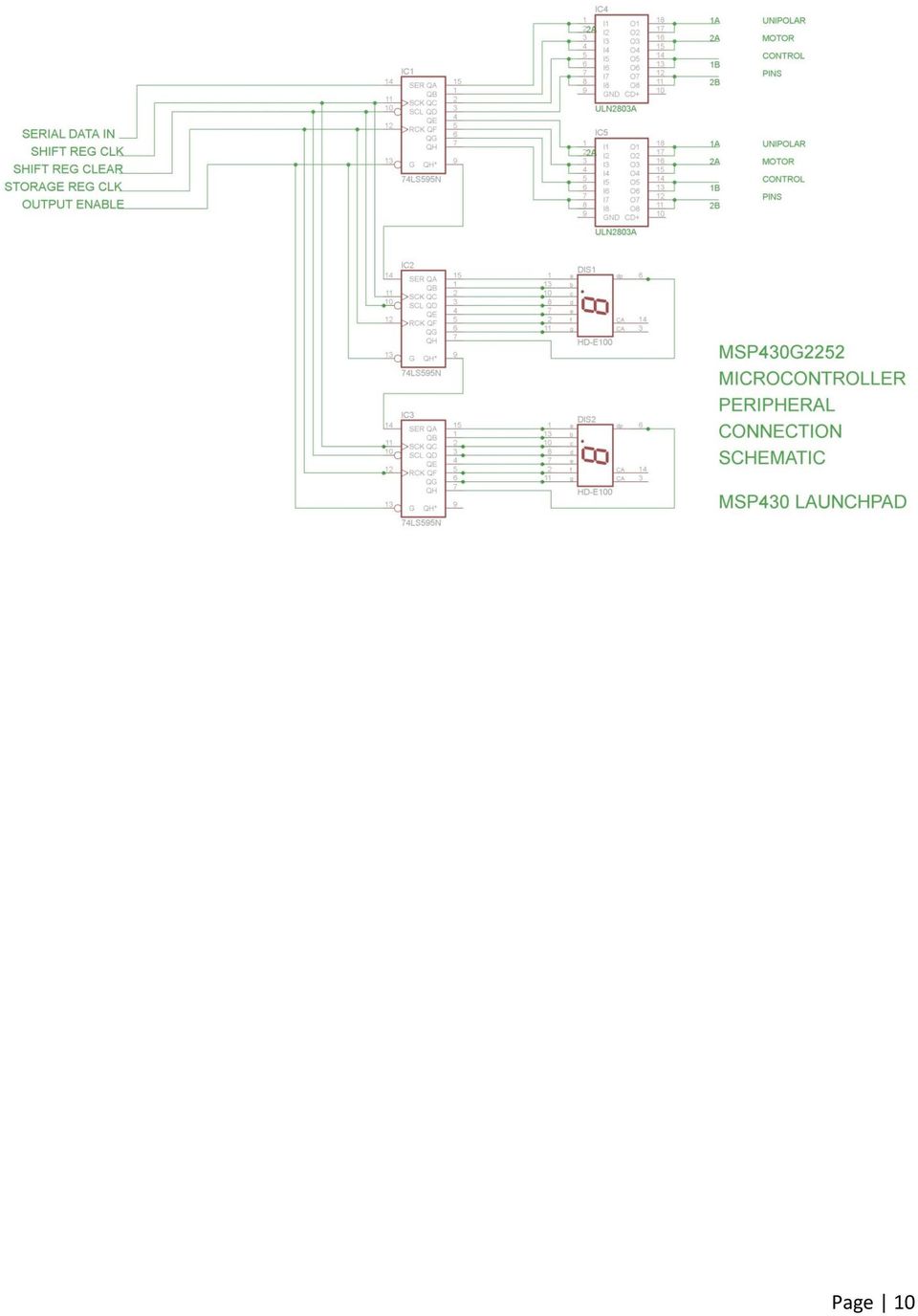
Table 1 Comparison of DC, Uni-Polar and Bi-polar Stepper Motors
 Electronics Exercise 3: Uni-Polar Stepper Motor Controller / Driver Mechatronics Instructional Laboratory Woodruff School of Mechanical Engineering Georgia Institute of Technology Lab Director: I. Charles
Construction and Application of a Computer Based Interface Card
 Session 4 Construction and Application of a Computer Based Interface Card Michael Combs Telescope Operations Engineer [email protected] Morehead State University Morehead, Kentucky Ahmad Zargari,
CHAPTER 11: Flip Flops
 CHAPTER 11: Flip Flops In this chapter, you will be building the part of the circuit that controls the command sequencing. The required circuit must operate the counter and the memory chip. When the teach
Access Control Using Smartcard And Passcode
 IOSR Journal of Electrical and Electronics Engineering (IOSR-JEEE) e-issn: 2278-1676 Volume 4, Issue 5 (Jan. - Feb. 2013), PP 29-34 Access Control Using Smartcard And Passcode Omorogiuwa Eseosa 1., Uhunmwangho
Technical Aspects of Creating and Assessing a Learning Environment in Digital Electronics for High School Students
 Session: 2220 Technical Aspects of Creating and Assessing a Learning Environment in Digital Electronics for High School Students Adam S. El-Mansouri, Herbert L. Hess, Kevin M. Buck, Timothy Ewers Microelectronics
Bob Rathbone Computer Consultancy
 Raspberry PI Stepper Motor Constructors Manual Bob Rathbone Computer Consultancy www.bobrathbone.com 20 th of December 2013 Bob Rathbone Raspberry PI Robotic Arm 1 Contents Introduction... 3 Raspberry
DEPARTMENT OF COMPUTER SCIENCE & ENGINEERING Question Bank Subject Name: EC6504 - Microprocessor & Microcontroller Year/Sem : II/IV
 DEPARTMENT OF COMPUTER SCIENCE & ENGINEERING Question Bank Subject Name: EC6504 - Microprocessor & Microcontroller Year/Sem : II/IV UNIT I THE 8086 MICROPROCESSOR 1. What is the purpose of segment registers
Data Acquisition Module with I2C interface «I2C-FLEXEL» User s Guide
 Data Acquisition Module with I2C interface «I2C-FLEXEL» User s Guide Sensors LCD Real Time Clock/ Calendar DC Motors Buzzer LED dimming Relay control I2C-FLEXEL PS2 Keyboards Servo Motors IR Remote Control
Digital Systems Based on Principles and Applications of Electrical Engineering/Rizzoni (McGraw Hill
 Digital Systems Based on Principles and Applications of Electrical Engineering/Rizzoni (McGraw Hill Objectives: Analyze the operation of sequential logic circuits. Understand the operation of digital counters.
8051 MICROCONTROLLER COURSE
 8051 MICROCONTROLLER COURSE Objective: 1. Familiarization with different types of Microcontroller 2. To know 8051 microcontroller in detail 3. Programming and Interfacing 8051 microcontroller Prerequisites:
Lecture N -1- PHYS 3330. Microcontrollers
 Lecture N -1- PHYS 3330 Microcontrollers If you need more than a handful of logic gates to accomplish the task at hand, you likely should use a microcontroller instead of discrete logic gates 1. Microcontrollers
A 5 Degree Feedback Control Robotic Arm (Haptic Arm)
") A 5 Degree Feedback Control Robotic Arm (Haptic Arm) 1 Prof. Sheetal Nirve, 2 Mr.Abhilash Patil, 3 Mr.Shailesh Patil, 4 Mr.Vishal Raut Abstract: Haptics is the science of applying touch sensation and control
A 5 Degree Feedback Control Robotic Arm (Haptic Arm) 1 Prof. Sheetal Nirve, 2 Mr.Abhilash Patil, 3 Mr.Shailesh Patil, 4 Mr.Vishal Raut Abstract: Haptics is the science of applying touch sensation and control
Lab 1 Course Guideline and Review
 Lab 1 Course Guideline and Review Overview Welcome to ECE 3567 Introduction to Microcontroller Lab. In this lab we are going to experimentally explore various useful peripherals of a modern microcontroller
Pulse Width Modulation Applications
 Pulse Width Modulation Applications Lecture 21 EE 383 Microcomputers Learning Objectives What is DTMF? How to use PWM to generate DTMF? How to use PWM to control a servo motor? How to use PWM to control
Controlling a Dot Matrix LED Display with a Microcontroller
 Controlling a Dot Matrix LED Display with a Microcontroller By Matt Stabile and programming will be explained in general terms as well to allow for adaptation to any comparable microcontroller or LED matrix.
Interfacing Analog to Digital Data Converters
 Converters In most of the cases, the PIO 8255 is used for interfacing the analog to digital converters with microprocessor. We have already studied 8255 interfacing with 8086 as an I/O port, in previous
MICROPROCESSOR. Exclusive for IACE Students www.iace.co.in iacehyd.blogspot.in Ph: 9700077455/422 Page 1
 MICROPROCESSOR A microprocessor incorporates the functions of a computer s central processing unit (CPU) on a single Integrated (IC), or at most a few integrated circuit. It is a multipurpose, programmable
Monitoring of Intravenous Drip Rate
 Monitoring of Intravenous Drip Rate Vidyadhar V. Kamble, Prem C. Pandey, Chandrashekar P. Gadgil, and Dinesh S. Choudhary Abstract A drip rate meter, for monitoring intravenous infusion, is developed using
Data Sheet. Adaptive Design ltd. Arduino Dual L6470 Stepper Motor Shield V1.0. 20 th November 2012. L6470 Stepper Motor Shield
 Arduino Dual L6470 Stepper Motor Shield Data Sheet Adaptive Design ltd V1.0 20 th November 2012 Adaptive Design ltd. Page 1 General Description The Arduino stepper motor shield is based on L6470 microstepping
Special Lecture. Basic Stamp 2 Programming. (Presented on popular demand)
") Special Lecture Basic Stamp 2 Programming (Presented on popular demand) Programming Environment Servo Motor: How It Work? The editor window consists of the main edit pane with an integrated explorer panel
Special Lecture Basic Stamp 2 Programming (Presented on popular demand) Programming Environment Servo Motor: How It Work? The editor window consists of the main edit pane with an integrated explorer panel
revolution Contents: Introduction Power 28-pin Project Board with input/output cables
 28-PIN IN IN PROJECT BOARD Contents: AXE020 28-pin Project Board with input/output cables Introduction The 28-pin project board is designed to allow rapid prototyping with 28-pin PICAXE microcontrollers.
Easy Step 1000 Stepper Driver Module
 Easy Step 1000 Stepper Driver Module STEPPER MOTOR DRIVER MODULE Example Connection Diagram 2 The Easy Step 1000 (ES1000) is intended to be the link between a microprocessor and stepper motor. The ES1000
Programming PIC Microcontrollers in PicBasic Pro Lesson 1 Cornerstone Electronics Technology and Robotics II
 Programming PIC Microcontrollers in PicBasic Pro Lesson 1 Cornerstone Electronics Technology and Robotics II Administration: o Prayer PicBasic Pro Programs Used in This Lesson: o General PicBasic Pro Program
Embedded Systems on ARM Cortex-M3 (4weeks/45hrs)
") Embedded Systems on ARM Cortex-M3 (4weeks/45hrs) Course & Kit Contents LEARN HOW TO: Use of Keil Real View for ARM Use ARM Cortex-M3 MCU for professional embedded application development Understanding
Embedded Systems on ARM Cortex-M3 (4weeks/45hrs) Course & Kit Contents LEARN HOW TO: Use of Keil Real View for ARM Use ARM Cortex-M3 MCU for professional embedded application development Understanding
Chen. Vibration Motor. Application note
 Vibration Motor Application note Yangyi Chen April 4 th, 2013 1 Table of Contents Pages Executive Summary ---------------------------------------------------------------------------------------- 1 1. Table
PROJECT PRESENTATION ON CELLPHONE OPERATED ROBOTIC ASSISTANT
 PROJECT PRESENTATION ON CELLPHONE OPERATED ROBOTIC ASSISTANT ELECTRONICS ENGINEERING DEPARTMENT SVNIT, SURAT-395007, INDIA Prepared by: Anurag Gupta (U05EC401) Dhrumeel Bakshi (U05EC326) Dileep Dhakal
0832 Dot Matrix Green Display Information Board User s Guide
 0832 Dot Matrix Green Display Information Board User s Guide DE-DP105_Ver1.0 0832 DOT MATRIX GREEN DISPLAY INFORMATI BOARD USER S GUIDE Table of contents Chapter1.Overview... 1 1.1. Welcome... 1 1.2. Quick
Design of an Insulin Pump. Purpose of an Insulin Pump:
 Design of an Insulin Pump Purpose of an Insulin Pump: Insulin is a hormone central to regulating carbohydrate and fat metabolism in the body. It is secreted regularly within the body and aids in converting
Micro-Step Driving for Stepper Motors: A Case Study
 Micro-Step Driving for Stepper Motors: A Case Study N. Sedaghati-Mokhtari Graduate Student, School of ECE, University of Tehran, Tehran, Iran n.sedaghati @ece.ut.ac.ir Abstract: In this paper, a case study
PART B QUESTIONS AND ANSWERS UNIT I
 PART B QUESTIONS AND ANSWERS UNIT I 1. Explain the architecture of 8085 microprocessor? Logic pin out of 8085 microprocessor Address bus: unidirectional bus, used as high order bus Data bus: bi-directional
Chapter 2 Logic Gates and Introduction to Computer Architecture
 Chapter 2 Logic Gates and Introduction to Computer Architecture 2.1 Introduction The basic components of an Integrated Circuit (IC) is logic gates which made of transistors, in digital system there are
EasyC. Programming Tips
 EasyC Programming Tips PART 1: EASYC PROGRAMMING ENVIRONMENT The EasyC package is an integrated development environment for creating C Programs and loading them to run on the Vex Control System. Its Opening
Lab Experiment 1: The LPC 2148 Education Board
 Lab Experiment 1: The LPC 2148 Education Board 1 Introduction The aim of this course ECE 425L is to help you understand and utilize the functionalities of ARM7TDMI LPC2148 microcontroller. To do that,
Using the Motor Controller
 The Motor Controller is designed to be a convenient tool for teachers and students who want to use math and science to make thing happen. Mathematical equations are the heart of math, science and technology,
Implementing SPI Communication Between MSP430 G2452 and LTC2382-16 ADC
 Implementing SPI Communication Between MSP430 G2452 and LTC2382-16 ADC Enwei Gu Nov. 12, 2011 MCU ADC MSP430- G2452 LTC2382-16 16- bits SPI Keywords 1 Abstract This document describes and shows how to
ETEC 421 - Digital Controls PIC Lab 10 Pulse Width Modulation
 ETEC 421 - Digital Controls PIC Lab 10 Pulse Width Modulation Program Definition: Write a program to control the speed of a dc motor using pulse width modulation. Discussion: The speed of a dc motor is
Programming A PLC. Standard Instructions
 Programming A PLC STEP 7-Micro/WIN32 is the program software used with the S7-2 PLC to create the PLC operating program. STEP 7 consists of a number of instructions that must be arranged in a logical order
Microcontroller Based Low Cost Portable PC Mouse and Keyboard Tester
 Leonardo Journal of Sciences ISSN 1583-0233 Issue 20, January-June 2012 p. 31-36 Microcontroller Based Low Cost Portable PC Mouse and Keyboard Tester Ganesh Sunil NHIVEKAR *, and Ravidra Ramchandra MUDHOLKAR
Four/Five Axis TB6560 CNC Driver Users Manual
 Four/Five Axis TB6560 CNC Driver Users Manual Revision 2.0. Oct. 16. 2009 1 Content 1. GENERAL INFORMATION... 3 1.1. Scope... 3 1.2. General Description... 3 1.3. Key Features... 3 2. Descriptions of 4/5-AXIS
Programming Logic controllers
 Programming Logic controllers Programmable Logic Controller (PLC) is a microprocessor based system that uses programmable memory to store instructions and implement functions such as logic, sequencing,
HT46R14A Single Phase AC Induction Motor Frequency Converter Application
 HT46R14A Single Phase AC Induction Motor Frequency Converter Application D/N:HA0095E Introductions Initially the main reason for using frequency conversion technology was for speed control, however to
Three Axis TB6560 CNC Driver Users Manual
 Three Axis TB6560 CNC Driver Users Manual Revision 2.0 Oct. 16. 2009 1 Content 1. GENERAL INFORMATION... 3 1.1. Scope... 3 1.2. General Description... 3 2. Descriptions of 3-AXIS CNC Board... 3 2.1. Photo
Implementing SPI Master and Slave Functionality Using the Z8 Encore! F083A
 Application Note Implementing SPI Master and Slave Functionality Using the Z8 Encore! F083A AN026701-0308 Abstract This application note demonstrates a method of implementing the Serial Peripheral Interface
Seven-Segment LED Displays
 Seven-Segment LED Displays Nicholas Neumann 11/19/2010 Abstract Seven-segment displays are electronic display devices used as an easy way to display decimal numerals and an alterative to the more complex
Soft processors for microcontroller programming education
 Soft processors for microcontroller programming education Charles Goetzman Computer Science University of Wisconsin La Crosse [email protected] Jeff Fancher Electronics Western Technical College
DS1104 R&D Controller Board
 DS1104 R&D Controller Board Cost-effective system for controller development Highlights Single-board system with real-time hardware and comprehensive I/O Cost-effective PCI hardware for use in PCs Application
INTRODUCTION TO SERIAL ARM
 INTRODUCTION TO SERIAL ARM A robot manipulator consists of links connected by joints. The links of the manipulator can be considered to form a kinematic chain. The business end of the kinematic chain of
UNIT 1 INTRODUCTION TO NC MACHINE TOOLS
 UNIT 1 INTRODUCTION TO NC MACHINE TOOLS Structure 1.1 Introduction Objectives 1.2 NC Machines 1.2.1 Types of NC Machine 1.2.2 Controlled Axes 1.2.3 Basic Components of NC Machines 1.2.4 Problems with Conventional
Computer and Set of Robots
 Lesson 11:DESIGN PROCESS EXAMPLES Mobile-Phone, Mobile- Computer and Set of Robots 1 Mobile Phone 2 Mobile phone SoC (System-on-Chip) Hardware units Microcontroller or ASIP (Application Specific Instruction
Location-Aware and Safer Cards: Enhancing RFID Security and Privacy
 Location-Aware and Safer Cards: Enhancing RFID Security and Privacy 1 K.Anudeep, 2 Mrs. T.V.Anantha Lakshmi 1 Student, 2 Assistant Professor ECE Department, SRM University, Kattankulathur-603203 1 [email protected],
Microcontroller Display Interfacing Techniques
 Display Interfacing Techniques Document Revision: 1.01 Date: September 13, 2006 16301 Blue Ridge Road, Missouri City, Texas 77489 Telephone: 1-713-283-9970 Fax: 1-281-416-2806 E-mail: [email protected] Web:
Electronic Rotary Table Divider V2.1 Construction
 Electronic Rotary Table Divider V2.1 Construction 2006,2013 Steve Ward ([email protected]) Legal: All documents, code, schematics, firmware etc are offered as an aid to the experienced constructor
MC433 Stepper Motor Controller
 MC433 Stepper Motor Controller 4 Axis, 10A PWM Hardware Reference Guide PCB Rev 1.1,1.1b MC433 Rev 1-1(b) Hardware Reference Guide Manual Revision 0.95 Warranty Statement SOC Robotics warrants that the
3BASIC RELAY INSTRUCTIONS
 M O D U L E T H R E E 3BASIC RELAY INSTRUCTIONS Key Points So far, you have learned about the components of the MicroLogix 1000 PLC, including the CPU, the memory system, the power supply, and the input/output
Inductance. Motors. Generators
 Inductance Motors Generators Self-inductance Self-inductance occurs when the changing flux through a circuit arises from the circuit itself. As the current increases, the magnetic flux through a loop due
dspace DSP DS-1104 based State Observer Design for Position Control of DC Servo Motor
 dspace DSP DS-1104 based State Observer Design for Position Control of DC Servo Motor Jaswandi Sawant, Divyesh Ginoya Department of Instrumentation and control, College of Engineering, Pune. ABSTRACT This
Microcontroller-based experiments for a control systems course in electrical engineering technology
 Microcontroller-based experiments for a control systems course in electrical engineering technology Albert Lozano-Nieto Penn State University, Wilkes-Barre Campus, Lehman, PA, USA E-mail: [email protected]
A Digital Timer Implementation using 7 Segment Displays
 A Digital Timer Implementation using 7 Segment Displays Group Members: Tiffany Sham u2548168 Michael Couchman u4111670 Simon Oseineks u2566139 Caitlyn Young u4233209 Subject: ENGN3227 - Analogue Electronics
Stepper motor I/O. Application Note DK9222-0410-0014 Motion Control. A General information on stepper motors
 Stepper motor Keywords Stepper motor Fieldbus Microstepping Encoder Phase current Travel distance control Speed interface KL2531 KL2541 Part A of this Application Example provides general information on
AN10850. LPC1700 timer triggered memory to GPIO data transfer. Document information. LPC1700, GPIO, DMA, Timer0, Sleep Mode
 LPC1700 timer triggered memory to GPIO data transfer Rev. 01 16 July 2009 Application note Document information Info Keywords Abstract Content LPC1700, GPIO, DMA, Timer0, Sleep Mode This application note
Atmel Norway 2005. XMEGA Introduction
 Atmel Norway 005 XMEGA Introduction XMEGA XMEGA targets Leadership on Peripheral Performance Leadership in Low Power Consumption Extending AVR market reach XMEGA AVR family 44-100 pin packages 16K 51K
Microcontroller to Sensor Interfacing Techniques
 to Sensor Interfacing Techniques Document Revision: 1.01 Date: 3rd February, 2006 16301 Blue Ridge Road, Missouri City, Texas 77489 Telephone: 1-713-283-9970 Fax: 1-281-416-2806 E-mail: [email protected]
An overview of Computerised Numeric Control (C.N.C.) and Programmable Logic Control (P.L.C.) in machine automation
 and Programmable Logic Control (P.L.C.) in machine automation") An overview of Computerised Numeric Control (C.N.C.) and Programmable Logic Control (P.L.C.) in machine automation By Pradeep Chatterjee, Engine Division Maintenance, TELCO, Jamshedpur 831010 E-mail: [email protected]
An overview of Computerised Numeric Control (C.N.C.) and Programmable Logic Control (P.L.C.) in machine automation By Pradeep Chatterjee, Engine Division Maintenance, TELCO, Jamshedpur 831010 E-mail: [email protected]
How to design an insulin pump
 How to design an insulin pump Learn about the purpose of an insulin pump, its overall workings, and the requirements needed for its design as well as implementation. By Asha Ganesan Applications Engineer
POCKET SCOPE 2. The idea 2. Design criteria 3
 POCKET SCOPE 2 The idea 2 Design criteria 3 Microcontroller requirements 3 The microcontroller must have speed. 3 The microcontroller must have RAM. 3 The microcontroller must have secure Flash. 3 The
MICROPROCESSOR AND MICROCOMPUTER BASICS
 Introduction MICROPROCESSOR AND MICROCOMPUTER BASICS At present there are many types and sizes of computers available. These computers are designed and constructed based on digital and Integrated Circuit
DKWF121 WF121-A 802.11 B/G/N MODULE EVALUATION BOARD
 DKWF121 WF121-A 802.11 B/G/N MODULE EVALUATION BOARD PRELIMINARY DATA SHEET Wednesday, 16 May 2012 Version 0.5 Copyright 2000-2012 Bluegiga Technologies All rights reserved. Bluegiga Technologies assumes
AUTOMATIC NIGHT LAMP WITH MORNING ALARM USING MICROPROCESSOR
 AUTOMATIC NIGHT LAMP WITH MORNING ALARM USING MICROPROCESSOR INTRODUCTION This Project "Automatic Night Lamp with Morning Alarm" was developed using Microprocessor. It is the Heart of the system. The sensors
4 Character 5x7 LED Matrix Display
 Mini project report on 4 Character 5x7 LED Matrix Display Submitted by Agarwal Vikas, MTech II, CEDT K.Sreenivasulu M.E (Micro) II, CEDT CENTRE FOR ELECTRONICS DESIGN AND TECHNOLOGY INDIAN INSTITUTE OF
DC Motor control Reversing
 January 2013 DC Motor control Reversing and a "Rotor" which is the rotating part. Basically there are three types of DC Motor available: - Brushed Motor - Brushless Motor - Stepper Motor DC motors Electrical
An Introduction to MPLAB Integrated Development Environment
 An Introduction to MPLAB Integrated Development Environment 2004 Microchip Technology Incorporated An introduction to MPLAB Integrated Development Environment Slide 1 This seminar is an introduction to
8-Bit Flash Microcontroller for Smart Cards. AT89SCXXXXA Summary. Features. Description. Complete datasheet available under NDA
 Features Compatible with MCS-51 products On-chip Flash Program Memory Endurance: 1,000 Write/Erase Cycles On-chip EEPROM Data Memory Endurance: 100,000 Write/Erase Cycles 512 x 8-bit RAM ISO 7816 I/O Port
How To Program A Microcontroller Board (Eb064) With A Psp Microcontroller (B064-74) With An Ios 2.5V (Power) And A Ppt (Power Control) (Power Supply) (
 With A Psp Microcontroller (B064-74) With An Ios 2.5V (Power) And A Ppt (Power Control) (Power Supply) (") dspic / PIC24 Multiprogrammer datasheet EB064-00 00-1 Contents 1. About this document... 2 2. General information... 3 3. Board layout... 4 4. Testing this product... 5 5. Circuit description... 6 Appendix
dspic / PIC24 Multiprogrammer datasheet EB064-00 00-1 Contents 1. About this document... 2 2. General information... 3 3. Board layout... 4 4. Testing this product... 5 5. Circuit description... 6 Appendix
Counters and Decoders
 Physics 3330 Experiment #10 Fall 1999 Purpose Counters and Decoders In this experiment, you will design and construct a 4-bit ripple-through decade counter with a decimal read-out display. Such a counter
How to Turn an AC Induction Motor Into a DC Motor (A Matter of Perspective) Steve Bowling Application Segments Engineer Microchip Technology, Inc.
 Steve Bowling Application Segments Engineer Microchip Technology, Inc.") 1 How to Turn an AC Induction Motor Into a DC Motor (A Matter of Perspective) Steve Bowling Application Segments Engineer Microchip Technology, Inc. The territory of high-performance motor control has
1 How to Turn an AC Induction Motor Into a DC Motor (A Matter of Perspective) Steve Bowling Application Segments Engineer Microchip Technology, Inc. The territory of high-performance motor control has
The Programming Interface
 : In-System Programming Features Program any AVR MCU In-System Reprogram both data Flash and parameter EEPROM memories Eliminate sockets Simple -wire SPI programming interface Introduction In-System programming
The Design of DSP controller based DC Servo Motor Control System
 International Conference on Advances in Energy and Environmental Science (ICAEES 2015) The Design of DSP controller based DC Servo Motor Control System Haiyan Hu *, Hong Gu, Chunguang Li, Xiaowei Cai and
ENGI E1112 Departmental Project Report: Computer Science/Computer Engineering
 ENGI E1112 Departmental Project Report: Computer Science/Computer Engineering Daniel Estrada Taylor, Dev Harrington, Sekou Harris December 2012 Abstract This document is the final report for ENGI E1112,
WORKING WITH STEPPER MOTORS
 19 WORKING WITH STEPPER MOTORS In past chapters we ve looked at powering robots using everyday continuous DC motors. DC motors are cheap, deliver a lot of torque for their size, and are easily adaptable
Microstep Driver Manual Version 6/13/2006
 Microstep Driver Manual Version 6/13/2006 Embedded Acquisition Systems 2517 Cobden Street Sterling Heights, MI 48310 http://www.embeddedtronics.com email [email protected] copyright 2003-2004 EAS
Microtronics technologies Mobile: 99707 90092
 For more Project details visit: http://www.projectsof8051.com/rfid-based-attendance-management-system/ Code Project Title 1500 RFid Based Attendance System Synopsis for RFid Based Attendance System 1.
Project Plan. Project Plan. May13-06. Logging DC Wattmeter. Team Member: Advisor : Ailing Mei. Collin Christy. Andrew Kom. Client: Chongli Cai
 Project Plan May13-06 Logging DC Wattmeter Team Member: Ailing Mei Andrew Kom Chongli Cai Advisor : Collin Christy Client: Garmin International David Hoffman Qiaoya Cui Table of Contents Need Statement...
SYSTEM 4C. C R H Electronics Design
 SYSTEM 4C C R H Electronics Design SYSTEM 4C All in one modular 4 axis CNC drive board By C R Harding Specifications Main PCB & Input PCB Available with up to 4 Axis X, Y, Z, A outputs. Independent 25
AN111: Using 8-Bit MCUs in 5 Volt Systems
 This document describes how to incorporate Silicon Lab s 8-bit EFM8 and C8051 families of devices into existing 5 V systems. When using a 3 V device in a 5 V system, the user must consider: A 3 V power
Pmod peripheral modules are powered by the host via the interface s power and ground pins.
 Digilent Pmod Interface Specification Revision: November 20, 2011 1300 NE Henley Court, Suite 3 Pullman, WA 99163 (509) 334 6306 Voice (509) 334 6300 Fax Introduction The Digilent Pmod interface is used
AMZ-FX Guitar effects. (2007) Mosfet Body Diodes. http://www.muzique.com/news/mosfet-body-diodes/. Accessed 22/12/09.
 Mosfet Body Diodes. http://www.muzique.com/news/mosfet-body-diodes/. Accessed 22/12/09.") Pulse width modulation Pulse width modulation is a pulsed DC square wave, commonly used to control the on-off switching of a silicon controlled rectifier via the gate. There are many types of SCR s, most
Pulse width modulation Pulse width modulation is a pulsed DC square wave, commonly used to control the on-off switching of a silicon controlled rectifier via the gate. There are many types of SCR s, most
Implementing a Digital Answering Machine with a High-Speed 8-Bit Microcontroller
 Implementing a Digital Answering Machine with a High-Speed 8-Bit Microcontroller Zafar Ullah Senior Application Engineer Scenix Semiconductor Inc. Leo Petropoulos Application Manager Invox TEchnology 1.0
Block 3 Size 0 KB 0 KB 16KB 32KB. Start Address N/A N/A F4000H F0000H. Start Address FA000H F8000H F8000H F8000H. Block 2 Size 8KB 16KB 16KB 16KB
 APPLICATION NOTE M16C/26 1.0 Abstract The following article describes using a synchronous serial port and the FoUSB (Flash-over-USB ) Programmer application to program the user flash memory of the M16C/26
FlexPak 3000 Digital DC Drive Software Reference Manual Version 4.3
 FlexPak 3000 Digital DC Drive Software Reference Manual Version 4.3 Instruction Manual D2-3405-2 The information in this manual is subject to change without notice. Throughout this manual, the following
GLOLAB Two Wire Stepper Motor Positioner
 Introduction A simple and inexpensive way to remotely rotate a display or object is with a positioner that uses a stepper motor to rotate it. The motor is driven by a circuit mounted near the motor and
The I2C Bus. NXP Semiconductors: UM10204 I2C-bus specification and user manual. 14.10.2010 HAW - Arduino 1
 The I2C Bus Introduction The I2C-bus is a de facto world standard that is now implemented in over 1000 different ICs manufactured by more than 50 companies. Additionally, the versatile I2C-bus is used
MANUAL FOR BREAKOUT BOARD HG06
 MANUAL FOR BREAKOUT BOARD HG06 INFORMATION IS SPECIFIC TO OUR PRODUCTS AND CAN CAUSE DAMAGE IF USED WITH NONE COMPATIBLE PRODUCTS SO PLEASE CHECK WITH YOUR SUPPLIER FOR COMPATIBILITY These drawings are
Digital I/O: OUTPUT: Basic, Count, Count+, Smart+
 Digital I/O: OUTPUT: Basic, Count, Count+, Smart+ The digital I/O option port in the 4-Series provides us with 4 optically isolated inputs and 4 optically isolated outputs. All power is supplied externally.
Micro800 Programmable Controllers. Bulletin 2080 Selection Guide
 Micro800 Programmable Controllers Bulletin 2080 Selection Guide Important User Information Solid state equipment has operational characteristics differing from those of electromechanical equipment. Safety
C8051F020 Utilization in an Embedded Digital Design Project Course. Daren R. Wilcox Southern Polytechnic State University Marietta, Georgia
 C8051F020 Utilization in an Embedded Digital Design Project Course Daren R. Wilcox Southern Polytechnic State University Marietta, Georgia Abstract In this paper, the utilization of the C8051F020 in an
Display Board Pulse Width Modulation (PWM) Power/Speed Controller Module
 Power/Speed Controller Module") Display Board Pulse Width Modulation (PWM) Power/Speed Controller Module RS0 Microcontroller LEDs Motor Control Pushbuttons Purpose: To demonstrate an easy way of using a Freescale RS0K2 microcontroller
Display Board Pulse Width Modulation (PWM) Power/Speed Controller Module RS0 Microcontroller LEDs Motor Control Pushbuttons Purpose: To demonstrate an easy way of using a Freescale RS0K2 microcontroller
Motor Fundamentals. DC Motor
 Motor Fundamentals Before we can examine the function of a drive, we must understand the basic operation of the motor. It is used to convert the electrical energy, supplied by the controller, to mechanical
DSO138 oscilloscope program upgrade method
 DSO138 oscilloscope program upgrade method Applicable models: 13801K, 13802K Program upgrade Principle The DSO138 is a SCM STM32F103C8 internal oscilloscope that is preinstalled with a flash bootloader,
OLED into Mobile Main Display
 OLED into Mobile Main Display Author: Jack Tsang Title: Senior Product Marketing Engineer Company: Solomon Systech Limited Introduction A decade after the Electro-luminescent (EL) effect was first discovered,
2.0 Command and Data Handling Subsystem
 2.0 Command and Data Handling Subsystem The Command and Data Handling Subsystem is the brain of the whole autonomous CubeSat. The C&DH system consists of an Onboard Computer, OBC, which controls the operation