TOYOTA STARTING SYSTEMS. General
|
|
|
- Joanna Bates
- 7 years ago
- Views:
Transcription
1 General Starting the engine is possibly the most important function of the vehicle's electrical system. The starting system performs this function by changing electrical energy from the battery to mechanical energy in the starting motor. This motor then transfers the mechanical energy, through gears, to the flywheel on the engine's crankshaft. During cranking, the flywheel rotates and the air-fuel mixture is drawn into the cylinders, compressed, and ignited to start the engine. Most engines require a cranking speed of about 200 rpm. Toyota Starting Systems Two different starting systems are used on Toyota vehicles. Both systems have two separate electrical circuits... a control circuit and a motor circuit. One has a conventional starting motor. This system is used on most older-model Toyotas. The other has a gear reduction starting motor. This system is used on most current Toyotas. A heavy-duty magnetic switch, or solenoid, turns the motor on and off. It is part of both the motor circuit and the control circuit. Both systems are controlled by the ignition switch and protected by a fusible link. On some models, a starter relay is used in the starter control circuit. On models with automatic transmission, a neutral start switch prevents starting with the transmission in gear. On models with manual transmission, a clutch switch prevents starting unless the clutch is fully depressed. On 4WD Truck and 4-Runner models, a safety cancel switch allows starting on hills without the clutch depressed. It does so by establishing an alternate path to ground. Page 1

2 Starting System Operation Page 2

3 Starting Motor Construction GENERAL The starter motors used on Toyota vehicles have a magnetic switch that shifts a rotating gear (pinion gear) into and out of mesh with the ring gear on the engine flywheel. Two types of motors are used: conventional and gear reduction. Both are rated by power output in kilowatts (KW)... the greater the output, the greater the cranking power. CONVENTIONAL STARTER MOTOR The conventional starter motor contains the components shown. The pinion gear is on the same shaft as the motor armature and rotates at the same speed. A plunger in the magnetic switch (solenoid) is connected to a shift lever. When activated by the plunger, the shift lever pushes the pinion gear and causes it to mesh with the flywheel ring gear. When the engine starts, an over-running clutch disengages the pinion gear to prevent engine torque from ruining the starting motor. This type of starter was used on most 1975 and older Toyota vehicles. It is currently used on certain Tercel models. Typical output ratings are 0.8, 0.9, and 1.0KW. In most cases, replacement starters for these older motors are gear-reduction motors. Page 3
 is connected to a shift lever. When activated by the plunger, the shift lever pushes the pinion gear and causes it to mesh with the flywheel ring gear.")
4 GEAR-REDUCTION STARTER MOTOR The gear-reduction starter motor contains the components shown. This type of starter has a compact, high-speed motor and a set of reduction gears. While the motor is smaller and weighs less than conventional starting motors, it operates at higher speed. The reduction gears transfer this torque to the pinion gear at 1/4 to 1/3 the motor speed. The pinion gear still rotates faster than the gear on a conventional starter and with much greater torque (cranking power). The reduction gear is mounted on the same shaft as the pinion gear. And, unlike in the conventional starter, the magnetic switch plunger acts directly on the pinion gear (not through a drive lever) to push the gear into mesh with the ring gear. This type of starter was first used on the 1973 Corona MKII with the 4M, six cylinder engine. It is now used on most 1975 and newer Toyotas. Ratings range from 0.8KW on most Tercels and some older models to as high as 2.5KW on the diesel Corolla, Camry and Truck. The cold-weather package calls for a 1.4KW or 1.6KW starter, while a 1.0KW starter is common on other models. The gear-reduction starter is the replacement starter for most conventional starters. Page 4
 to push the gear into mesh with the ring gear.")
5 Starting Motor Operation CONVENTIONAL STARTER MOTOR IGNITION SWITCH IN "ST" Current flows from the battery through terminal "50" to the hold-in and pull-in coils. Then, from the pull-in coil, current flows through terminal "C" to the field coils and armature coils. Voltage drop across the pull-in coil limits the current to the motor, keeping its speed low. The solenoid plunger pulls the drive lever to mesh the pinion gear with the ring gear. The screw spline and low motor speed help the gears mesh smoothly. PINION AND RING GEARS ENGAGED When the gears are meshed, the contact plate on the plunger turns on the main switch by closing the connection between terminals "30" and "C." More current goes to the motor and it rotates with greater torque (cranking power). Current no longer flows in the pull-in coil. The plunger is held in position by the hold-in coil's magnetic force. IGNITION SWITCH IN "ON" Current no longer flows to terminal "50," but the main switch remains closed to allow current flow from terminal "C" through the pull-in coil to the hold-in coil. The magnetic fields in the two coils cancel each other, and the plunger is pulled back by the return spring. The high current to the motor is cut off and the pinion gear disengages from the ring gear. A spring-loaded brake stops the armature. Page 5

6 GEAR-REDUCTION STARTER MOTOR IGNITION SWITCH IN "ST" Current flows from the battery through terminal "50" to the hold-in and pull-in coils. Then, from the pull-in coil, current flows through terminal "C" to the field coils and armature coils. Voltage drop across the pull-in coil limits the current to the motor, keeping its speed low. The magnetic switch plunger pushes the pinion gear to mesh with the ring gear. he screw and low motor speed help the gears mesh smoothly. PINION AND RING GEARS ENGAGED When the gears are meshed, the contact plate on he plunger turns on the main switch by closing the connection between terminals "30" and "C." More current goes to the motor and it rotates with greater torque. Current no longer flows in the pull-in coil. The plunger is held in position by the hold-in coil's magnetic force. IGNITION SWITCH IN "ON" Current no longer flows to terminal "50," but the main switch remains closed to allow current flow from terminal "C" through the pull-in coil to the hold-in coil. The magnetic fields in the two coils cancel each other, and the plunger is pulled back by the return spring. The high current to the motor is cut off and the pinion gear disengages from the ring gear. The armature has less inertia than the one in a conventional starter. Friction stops it, so a brake is not needed. Page 6

7 OVER-RUNNING CLUTCH Both types of starter motors used on Toyota starting systems have a one-way clutch, or overrunning clutch. This clutch prevents damage to the starter motor once the engine has been started. It does so, by disengaging its housing (which rotates with the motor armature) from an inner race which is combined with the pinion gear. Spring loaded wedged rollers are used. Without an over-running clutch, the starter motor would be quickly destroyed if engine torque was transferred through the pinion gear to the armature. Page 7

8 Diagnosis and Testing The starting system requires little maintenance. Simply, keep the battery fully charged and all electrical connections clean and tight. Diagnosis of starting system problems is relatively easy. The system combines electrical and mechanical components. The cause of a starting problem may be electrical (e.g., faulty switch) or mechanical (e.g., wrong engine oil or a faulty flywheel ring gear). Specific symptoms of starting system problems include: The engine will not crank; The engine cranks slowly; The starter keeps running; The starter spins, but the engine will not crank; and, The starter does not engage or disengage properly. For each of these problems, refer to the chart below for the possible causes and needed actions. Diagnosis starts with a thorough visual inspection. Testing includes: a starter motor current draw test, starter circuit voltage drop tests, operational and continuity checks of control components, and starter motor bench tests. Page 8

9 VISUAL INSPECTION A visual inspection of the starting system can uncover a number of simple, easy-to-correct problems. SAFETY FIRST: The same safety considerations used in checking the battery apply here. Remove rings, wristwatch, other jewelry that might contact battery terminals. Wear safety glasses and protective clothing. Be careful not to spill electrolyte and know what to do if electrolyte gets in your eyes, on your skin or clothing, or on the car's finish. Write down programmed settings on electronic components. Avoid causing sparks. STARTING PERFORMANCE: Check the starting performance. Problem symptoms, possible causes, and needed actions are shown in the chart on the previous page. BATTERY CHECKS: Inspect the battery for corrosion, loose connections. Check the electrolyte level, condition of the plates and separators, and state of charge (specific gravity or open-circuit voltage). Load test the battery. It must be capable of providing at least 9.6 volts during cranking. STARTER CABLES: Check the cable condition and connections. Insulation should not be worn or damaged. Connections should be clean and tight. STARTER CONTROL CIRCUIT: Check the operation of the ignition switch. Current should be supplied to the magnetic switch when the ignition is "on" and the clutch switch or neutral start switch is closed. Faulty parts that prevent cranking can be located using a remote-control starter switch and a jumper wire. Use the "split half" diagnosis method. Ohmmeter checks can also identify component problems. Page 9

10 CURRENT DRAW TEST A starter current draw test provides a quick check of the entire starting system. With the Sun VAT-40 tester, it also checks battery's cranking voltage. If another type of tester is used, follow the manufacturer's recommended procedure. The starting current draw and cranking voltage should meet the specifications listed for the Toyota model being tested. Typical current draw specs are amps for 4-cylinder models and 175 amps for 6-cylinder models. Cranking voltage specs range from 9.6 to 11 volts. Always refer to the correct repair manual. Only perform the test with the engine at operating temperature. The following steps outline a typical procedure for performing a current draw test on a starting system: 1. This test should be made only with a serviceable battery. The specific gravity readings at 800 F should average at least (50% charged). Charge the battery, if necessary. 2. Prepare the tester: Rotate the Load Increase control to OFF. Check each meter's mechanical zero. Adjust, if necessary. Connect the tester Load Leads to the battery terminals; RED to positive, BLACK to negative. NOTE: Battery open-circuit voltage should be at least 12.2 volts (50% charged). If not, the battery requires charging. Set Volt Selector to INT 18V. Tester voltmeter should indicate battery open-circuit voltage. Set Test Selector to #2 CHARGING. Adjust ammeter to read ZERO using the electrical Zero Adjust control. 3. Connect the clamp-on Amps Pickup around the battery ground cable or cables. 4. Make sure all lights and accessories are off and vehicle doors are closed. 5. Set the Test Selector switch to #1 STARTING. 6. Disable the ignition so the engine does not start during testing. 7. Crank the engine, while observing the tester ammeter and voltmeter. Cranking speed should be normal ( rpm). Current draw should not exceed the maximum specified. Cranking voltage should be at or above the minimum specified. 8. Restore the engine to starting condition and remove tester leads. TEST RESULTS: High current draw and low cranking speed usually indicate a faulty starter. High current draw may also be caused by engine problems. A low cranking speed with low current draw, but high cranking voltage, usually indicates excessive resistance in the starter circuit. Remember that the battery must be fully charged and its connections tight to insure accurate results. Page 10

11 VOLTAGE-DROP TESTS Voltage-drop testing can detect excessive resistance in the starting system. High resistance in the starter motor circuit (power side or ground side) will reduce current to the starting motor. This can cause slow cranking speed and hard starting. High resistance in the starter control circuit will reduce current to the magnetic switch. This can cause improper operation or no operation at all. A Sun VAT-40 tester or separate voltmeter can be used. The following steps outline a typical procedure for performing voltage-drop tests on the starting system: Motor Circuit (insulated Side) 1. If using the Sun VAT-40, set the Volt Selector to EXT 3V. For other voltmeters, use a low scale. 2. Connect the voltmeter leads... RED to the battery positive (+) terminal, BLACK to terminal "C" on the starter motor magnetic switch. 3. Disable the ignition so the engine cannot start during testing. NOTE: On models with the Integrated Ignition Assembly, disconnect the "IIA" plug. On others, disconnect the power plug to the remote igniter assembly (black-orange wire). 4. Crank the engine and observe the voltmeter. Less than 0.5 volt indicates acceptable resistance. More than 0.5 volt indicates excessive resistance. This could be caused by a damaged cable, poor connections, or a defective magnetic switch. 5. If excessive resistance is indicated, locate the cause. Acceptable voltage drops are 0.3 volt across the magnetic switch, 0.2 volts for the cable, and zero volts for the cable connection. Repair or replace components, as needed. Page 11
 1.")
12 Motor Circuit (Ground Side) 1. Connect the voltmeter leads... RED to the starter motor housing, BLACK to the battery ground (-) terminal. 2. Crank the engine and observe the voltmeter. Less than 0.2 volt indicates acceptable resistance. More than 0.2 volt indicates excessive resistance. This could be caused by a loose motor mount, a bad battery ground, or a loose connection. Repair or replace components as necessary. Make sure engine-to-body ground straps are secure. Control Circuit 1. Connect the voltmeter leads... RED to the battery positive (+) terminal, BLACK to terminal "50" of the starting motor. 2. On vehicles with automatic transmission, place the lever in Park or Neutral. On vehicles with manual transmission, depress the clutch. (NOTE: A jumper wire could be used to bypass either of these switches). 3. Crank the engine and observe the voltmeter. Less than.5 volt is acceptable. If the current draw was high or cranking speed slow, the starter motor is defective. More than.5 volt indicates excessive resistance. Isolate the trouble and correct the cause. 4. Check the neutral start switch or clutch switch for excessive voltage drop. Also check the ignition switch. Adjust or replace a defective switch, as necessary. 5. An alternate method to checking the voltage drop across each component is to leave the voltmeter connected to the battery (+) terminal and move the voltmeter negative lead back through the circuit toward the battery. The point of high resistance is found between the point where voltage drop fell within specs and the point last checked. Page 12
 terminal, BLACK to terminal \"50\" of the starting motor. 2. On vehicles with automatic transmission, place the lever in Park or Neutral.")
13 COMPONENT TESTS For the various tests on starting system components, refer to the appropriate Toyota repair manual for testing procedures and specifications. Ignition Switch and Key The ignition switch should be checked both mechanically as well as electrically. Make sure the switch turns smoothly, without binding. And, check the ignition key for wear or metal chips that might cause the switch to stick in the "start" position. Some duplicate keys have caused this problem. If an electrical problem is suspected, disconnect the battery and check the switch for proper operation and continuity using an ohmmeter. Starter Relay Continuity Check: Using an ohmmeter, check for continuity between terminals 1 and 3, and, for no continuity, between terminals 2 and 4. Replace the relay if continuity is not as specified. Operational Check: Apply battery voltage across terminals 1 and 3 and check for continuity between terminals 2 and 4. Replace the relay if operation is not as specified. Neutral Start Switch If the engine will start with the shift selector in any range other than "N" or "P," adjust the switch. First, loosen the switch bolt and set the selector to "N." Then, disconnect the switch connector and connect an ohmmeter between terminals 2 and 3. Adjust the switch until there is continuity. (Refer to appropriate Service Manual for specific vehicle procedures.) Page 13

14 Clutch Start Switch Follow the procedure given in Toyota repair manuals for checking pedal height and freeplay. Then, check the switch for proper operation and continuity. Using an ohmmeter on the switch connector, there should be continuity when the switch is ON (clutch depressed) and no continuity when the switch is OFF (clutch not depressed). If continuity is not as specified, replace the switch. Safety Cancel Switch Continuity Checks: Using an ohmmeter, there should be no continuity between terminals 2 and 1, 3 and 1, or 2 and 3. If there is continuity, replace the switch. Operational Checks: Connect a battery between terminals 3 and 1 as shown. No continuity should be seen between terminals 1 and 2. But, when the switch is pushed "on," there should be continuity. If operation is not as specified, replace the safety cancel switch. Page 14

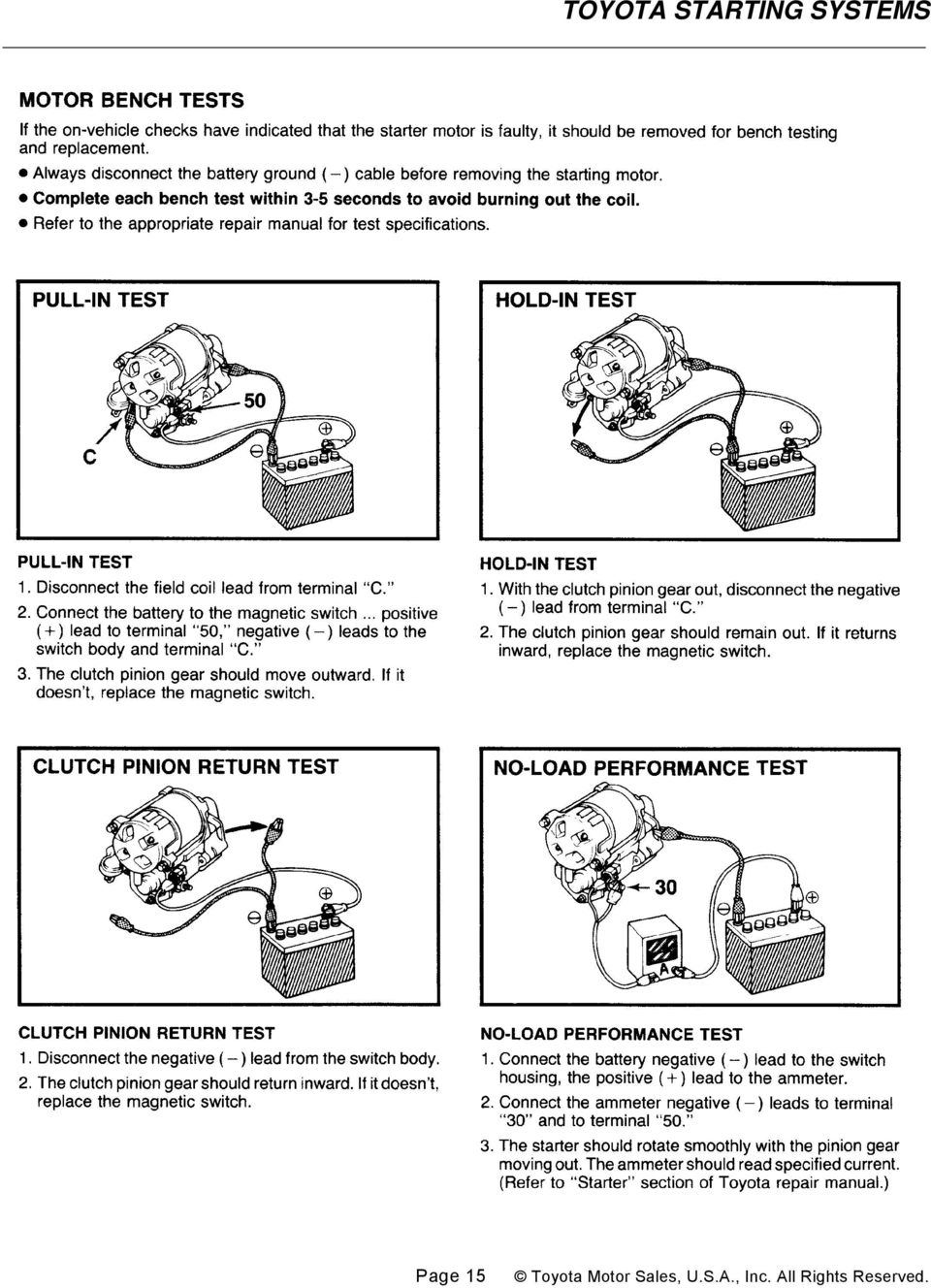
15 Page 15
16 SELF TEST This brief self-test will help you measure your understanding of The Starting System. The style is the same as that used for A.S.E. certification tests. The answers to this self test are shown on next page. 1. The starting system has two circuits. They are the: A. motor circuit and ignition circuit B. insulated circuit and power circuit C. motor circuit and control circuit D. ground circuit and control circuit 2. A basic starter control circuit energizes the magnetic switch through the ignition switch and the: A. solenoid B. neutral start switch C. starter clutch D. regulator 3. On a Toyota gear-reduction starter, the plunger in the magnetic switch: A. pulls a drive lever to mesh the gears B. pushes the pinion gear into mesh with the ring gear C. is held in place by the pull-in coil D. disengages the pinion gear from the starter armature 4. When an engine starts, the pinion gear is disconnected from the starter by the: A. magnetic switch B. plunger C. over-running clutch D. switch return spring 5. If the engine cranks too slow to start, the problem may be caused by: 6. If a starter motor spins but does not engage and crank the engine, the problem is most likely caused by a bad: A. magnetic switch B. over-running clutch C. positive battery cable D. ignition switch 7. When performing a starter current draw test, low current draw usually indicates: A. high resistance B. a bad starter C. a discharged battery D. a short in the starter 8. When performing a starter current draw test, high current draw usually indicates: A. a discharged battery B. high resistance C. battery terminal corrosion D. engine problems or a bad starter 9. A test of a starting system reveals that the voltage drop between the battery positive (+) post and the starter motor terminal "C" is about one volt. The most probable cause is: A. low resistance in the motor circuit B. high resistance in the motor circuit C. low resistance in the control circuit D. high resistance in the control circuit 10. The voltage drop on the ground side of the starter motor circuit should be no more than: A. battery voltage B. 0.1 volt C. 0.2 volt D. 0.5 volt A. engine problems B. a faulty neutral start switch C. an open relay in the control circuit D. a damaged pinion gear Page 16

17 SELF-TEST ANSWERS For the preceding self-test on The Starting System, the following best complete the sentence or answer the question. In cases where you may disagree with the choice - or may simply want to reinforce your understanding - please review the appropriate workbook page or pages noted. 1. "C" - The starting system has two separate electrical circuits... a control circuit and a motor circuit. (Page 1.) 9. "B" - With the voltmeter leads connected between the battery (+) terminal and the motor "C" terminal, a reading of more than 0.5 volt indicates excessive resistance (in the motor circuit). (Page 11.) 10. "C" - With the voltmeter leads connected between the battery (-) terminal and the motor housing, a reading of more than 0.2 volt indicates excessive resistance (in the motor ground circuit). (Page 12.) 2. "B" - If the transmission is in gear, the control circuit between the ignition switch and starter magnetic switch is interrupted by the neutral start switch. (Page 2.) 3. "B" - Unlike in the conventional starter, the magnetic switch plunger acts directly on the pinion gear (not through a drive lever) to push the gear into mesh with the ring gear. (Page 4.) 4. "C" - An over-running clutch disengages the pinion gear and prevents damage to the starter motor when the engine starts. (Page 7.) 5. "A" - If the engine cranks too slow to start, the cause may be a discharged battery, loose or corroded connections, a faulty starter, or engine problems such as the wrong oil. (Page 8.) 6. "B" - If the starter motor spins, but the engine will not crank, check the over-running clutch. (Page 8.) 7. "A" - Low current draw, with a low cranking speed and high cranking voltage, usually indicates excessive resistance in the starting circuit. (Page 10.) 8. "D" - High current draw, with a low cranking speed, usually indicates a faulty starter or engine problems such as the wrong oil or ignition timing. (Page 10.) Page 17
 terminal and the motor \"C\" terminal, a reading of more than 0.5 volt indicates excessive resistance (in the motor circuit). (Page 11.")
18 ASSIGNMENT NAME: 1. List the two staring system circuits. 2. List the components that make up the control circuit. 3. List the components that make up the motor circuit. 4. Explain in detail how a Conventional Starter differs from that of a Gear Reduction Starter. 5. Explain why an overrunning clutch is needed and how it works. 6. Explain how the starter drive pinion engages (pushed out) with the ring gear when the ignition key is turned to the Start position. 7. List and describe the five items included in a Visual Inspection. 8. Explain in detail the steps taken in order to perform a Current Draw Test. 9. Explain the procedure and the need for a voltage drop test of the Motor Circuit

The Starting System. Section 4. Starting System Overview. Starter. The starting system:
 The Starting System Starter The starter motor drives the engine through a pinion gear that engages the ring gear on the flywheel. Fig. 4-01 TL623f401c Starting System Overview The starting system: Uses
The Charging System. Section 5. Charging System. Charging System. The charging system has two essential functions:
 The Charging System Charging System The charging system has two essential functions: Generate electrical power to run the vehicle s electrical systems Generate current to recharge the vehicle s battery
TOYOTA ELECTRONIC TRANSMISSION CHECKS & DIAGNOSIS
 Checks and Adjustments The transmission requires regular maintenance intervals if it is to continue to operate without failure. As we discussed in previous sections, transmission fluid loses certain properties
SHIFT INTERLOCK SYSTEM SHIFT INTERLOCK SYSTEM
 SHIFT INTERLOCK SYSTEM The shift lock system is designed to ensure the proper operation of the automatic transmission. The driver must depress the brake pedal in order to move the gear selector from Park
TOYOTA ELECTRONIC CONTROL TRANSMISSION
 Electronic Control Transmission (ECT) The Electronic Control Transmission is an automatic transmission which uses modern electronic control technologies to control the transmission. The transmission itself,
Diagnosing and Understanding Starting Problems on the ZR-1 Marc Haibeck 28-Sep-13
 Diagnosing and Understanding Starting Problems on the ZR-1 Marc Haibeck 28-Sep-13 There are three basic failure conditions: - A VATS security system lockout - A click from the starter solenoid but no engine
FUEL-16, Troubleshooting Fuel Supply Problems
 FUEL-16, Troubleshooting Fuel Supply Problems Introduction This procedure is used to troubleshooting fuel supply problems including failure of the fuel pump to start during engine cranking. Fuel Pump Not
Windshield Wiper Motors
 Windshield Wiper Motors Originally posted by Dan Masters, danmas@aol.com Also see http://www.advanceautowire.com/ WIPER OPERATION: There are three major components to a wiper motor: Motor Rotary to linear
12-Volt Negative Ground Installation Instructions
 12-Volt Negative Ground Installation Instructions For Part Number: 1141, 1164, 1165, 1181 CAUTION!!! Before installing, please read the following important information... 1. The Ignitor is designed for
VEHICLE SPEED CONTROL SYSTEM
 PL VEHICLE SPEED CONTROL SYSTEM 8H - 1 VEHICLE SPEED CONTROL SYSTEM TABLE OF CONTENTS page DESCRIPTION AND SPEED CONTROL SYSTEM...1 SPEED CONTROL SERVO-PCM OUTPUT....2 SPEED CONTROL SWITCHES PCM INPUT...2
ENGINE ELECTRICAL SYSTEM
 ENGINE ELECTRICAL SYSTEM Return To Main Table of Contents GENERAL... 2 IGNITION SYSTEM... 4 CHARGING SYSTEM... 21 STARTING SYSTEM... 38 GENERAL GENERAL SPECIFICATIONS Distributor MPI FBC Type Contact pointless
UNIT 3 AUTOMOBILE ELECTRICAL SYSTEMS
 UNIT 3 AUTOMOBILE ELECTRICAL SYSTEMS Automobile Electrical Structure 3.1 Introduction Objectives 3.2 Ignition System 3.3 Requirement of an Ignition System 3.4 Types of Ignition 3.4.1 Battery or Coil Ignition
Essential Electrical Concepts
 Essential Electrical Concepts Introduction Modern vehicles incorporate many electrical and electronic components and systems: Audio Lights Navigation Engine control Transmission control Braking and traction
PENNTEX FOUR-STEP CHARGING SYSTEM TEST AND GENERAL INFORMATION FOR ANY PENNTEX SYSTEM EXCEPT 2009-UP FORDS WITH A PX-7000 VOLTAGE REGULATOR
 PENNTEX FOUR-STEP CHARGING SYSTEM TEST AND GENERAL INFORMATION FOR ANY PENNTEX SYSTEM EXCEPT 2009-UP FORDS WITH A PX-7000 VOLTAGE REGULATOR PennTex Industries, Inc. is a manufacturer of Heavy Duty Charging
BATTERIES. Battery Types. General. Battery Functions
 General The battery is the primary "source" of electrical energy on Toyota vehicles. It stores chemicals, not electricity. Two different types of lead in an acid mixture react to produce an electrical
6 & 12 Volt Battery and Systems Tester with 100 Amp Load
 6 & 12 Volt Battery and Systems Tester with 100 Amp Load Form No. 841-731 -000 DESCRIPTION This Load Tester tests 6 or 12 volt automotive-size lead-acid batteries under load. It will also test 6 or 12
Describe the procedure used to check for spark. Discuss what to inspect and look for during a visual inspection of the ignition system.
 CHAPTER 20 OBJECTIVES Describe the procedure used to check for spark. Discuss what to inspect and look for during a visual inspection of the ignition system. List the steps necessary to check and/or adjust
Battery Tester. GxT Incorporated, Cheboygan MI, U.S.A. All Rights Reserved E040-01G. 40 & 42HD Operator s Manual
 Battery Tester GxT Incorporated, Cheboygan MI, U.S.A. All Rights Reserved E040-01G 40 & 42HD Operator s Manual SPECIFICATIONS Measurement Range...Ferret 40... Ferret 42HD Battery Volts... 4.0 to 19.99...
ENGINE COOLING SYSTEM
 ENGINE COOLING SYSTEM 1988 Toyota Celica 1987-88 TOYOTA Engine Cooling Systems Celica DESCRIPTION The basic liquid cooling system consists of a radiator, water pump, thermostat, cooling fan, pressure cap,
ALTERNATOR & REGULATOR - HITACHI
 ALTERNATOR & REGULATOR - HITACHI 1990 Nissan 240SX 1990-91 ELECTRICAL Alternators & Regulators - Hitachi 1990 Axxess, Pulsar NX 1991 Maxima, NX, Pathfinder, Pickup, Sentra, Stanza, 240SX & 300ZX NOTE:
Class 5 to 7 Truck and Bus Hydraulic Brake System
 Class 5 to 7 Truck and Bus Hydraulic Brake System Diagnostic Guide 1st Edition * 5+0 Important Service tes The information in this publication was current at the time of printing. The information presented
Starter Motor Repair
 Starter Motor Repair Well... today folks we will unfold the starter motor chapter of our 33. Starter motor is one of the parts that is highly stressed in our car as it has the primary role of starting
ANALOG AND DIGITAL METERS ANALOG VS. DIGITAL METERS VOLTMETERS ANALOG AND DIGITAL
 ANALOG VS. DIGITAL METERS Ultimately, your diagnosis of vehicle electrical system problems will come down to using a voltmeter, ammeter, or ohmmeter to pinpoint the exact location of the problem. There
Left Hand Limit Switch. Housing. Left Hand. Connections. Motor Connector BROWN PURPLE GRAY BLACK DARK BLUE BLACK BROWN BROWN LIGHT BLUE.
 LIGHT BLUE GRAY PURPLE Circuit Breaker Intput Circuit Breaker Output #1 Relay Left Hand Limit Switch Housing Left Hand Motor Connector Right Hand Limit Switch on Radiator Support Right Hand Limit Switch
Chapter 7 Hydraulic System Troubleshooting
 Chapter 7 Hydraulic System Troubleshooting General The following troubleshooting information is provided as a general guide to identify, locate and correct problems that may be experienced with the hydraulic
EVANS ELECTRONIC TEMPERATURE CONTROL TROUBLESHOOTING GUIDE for systems equipped with electric coolant valve and external PC board.
 EVANS ELECTRONIC TEMPERATURE CONTROL TROUBLESHOOTING GUIDE for systems equipped with electric coolant valve and external PC board. This Troubleshooting Guide covers the electric coolant valve and control
i ChatterBox! Motorcycle Security
 i Before you Start the Installation * Please read this manual to become familiar with the requirements necessary to complete the installation. * Use a high quality multi-meter to test all wires before
1993 ACCESSORIES & EQUIPMENT Volkswagen Instrument Panels. Volkswagen; EuroVan, Passat
 Article Text Saturday, March 18, 2000 10:33PM ARTICLE BEGINNING 1993 ACCESSORIES & EQUIPMENT Volkswagen Instrument Panels Volkswagen; EuroVan, Passat DESCRIPTION & OPERATION Instrument cluster for most
Section 1 Overview of Heavy-Duty Auto Throttle Controls. Heavy Duty Auto Throttle Applications
 Section 1 Overview of Heavy-Duty Auto Throttle Controls Heavy Duty Auto Throttle Applications Utility and Maintenance Vehicles Increases engine RPM to provide full current output of the alternator when
Diesel Engine starting Systems
 chapter 7 Diesel Engine starting Systems Learning Objectives Key Terms After reading this chapter, the student should be able to: 1. Identify all main components of a diesel engine starting system 2. Describe
AUTOMATIC TRANSMISSION IN-CAR DIAGNOSTICS
 Learning Guide CHASSIS ELECTRICAL SPECIALIST AUTOMATIC TRANSMISSION IN-CAR DIAGNOSTICS COURSE NUMBER: C050-01 Notice Due to the wide range of vehicles makes and models, the information given during the
2001 Mercedes-Benz ML320
 MODEL IDENTIFICATION 2001-04 STARTING & CHARGING SYSTEMS Starters - 163 Chassis WARNING: Vehicles are equipped with air bag supplemental restraint system. Before attempting any repairs involving steering
INSPECTION BEFORE RIDING
 INSPECTION BEFORE RIDING Check the following items before riding. ITEM Engine cum transmission oil Fuel Tyres Battery Speedometer Lighting Steering Throttle Clutch Brakes Wheels WHAT TO CHECK FOR Availability
AUTO TRANS DIAGNOSIS Article Text 1998 Volkswagen Passat This file passed thru Volkswagen Technical Site - http://volkswagen.msk.
 AUTO TRANS DIAGNOSIS Article Text 1998 Volkswagen Passat This file passed thru Volkswagen Technical Site - http://volkswagen.msk.ru ARTICLE BEGINNING 1997-98 AUTOMATIC TRANSMISSIONS Volkswagen Shift Interlock
ANTI-THEFT SYSTEM. 1995 Volvo 850 DESCRIPTION & OPERATION BASIC ALARM. 1995-96 ACCESSORIES & EQUIPMENT Volvo Anti-Theft Systems
 ANTI-THEFT SYSTEM 1995 Volvo 850 1995-96 ACCESSORIES & EQUIPMENT Volvo Anti-Theft Systems 850 DESCRIPTION & OPERATION WARNING: Deactivate air bag system before performing any service operation. For 1995
12 Volt 30 Amp Digital Solar Charge Controller
 12 Volt 30 Amp Digital Solar Charge Controller User s Manual WARNING Read carefully and understand all INSTRUCTIONS before operating. Failure to follow the safety rules and other basic safety precautions
Operating Precautions: User configuration options:
 A Division of Lippert Components, Inc. PNP BED-LIFT USERS MANUAL Product Usage: This product is designed and intended ONLY to be used as a Bed-Lift mechanism. Any other use of this system will void any
BOSCH D-JETRONIC Volkswagen: Type 3 & 4
 BOSCH D-JETRONIC Volkswagen: Type 3 & 4 MANIFOLD PRESSURE CONTROL SYSTEM (MPC) DESCRIPTION The Bosch D-Jetronic electronic fuel injection system is composed of 3 major subsystems: the air intake system,
If you accidentally get battery acid on your skin, flush it with lots of water
 RV Battery Savvy To properly maintain and extend the life of your RV batteries you need to have a basic understanding of what a battery is and how it works. Batteries used in RVs are lead acid batteries.
COOL-01, Cooling Fan Operation and Troubleshooting
 COOL-01, Cooling Fan Operation and Troubleshooting Table of Contents Introduction Early 944s With Air Conditioning Cooling Fan Operation On Early 944s With Air Conditioning Testing Fan Relay One Early
DIAGNOSIS SYSTEM (3S GTE and 5S FE)
") Diagnosis System (3SGTE and 5SFE) FI39 DIAGNOSIS SYSTEM (3SGTE and 5SFE) DESCRIPTION The ECM contains a builtin, selfdiagnosis system by which troubles with the engine signal network are detected and a
Diagnosis System (3SGTE and 5SFE) FI39 DIAGNOSIS SYSTEM (3SGTE and 5SFE) DESCRIPTION The ECM contains a builtin, selfdiagnosis system by which troubles with the engine signal network are detected and a
Cranking Motors...Or Starters To The Rest Of Us
 Cranking Motors Or Starters To The Rest Of Us. It should come as no surprise that the theory of how a starter works is much the same as how the generator works. This means all the time and effort you spent
Electronic Brake Controller Hayes Brake Controller Company ENERGIZE III P/N # 81741B or ENERGIZE XPC P/N #81745 OPERATION MANUAL
 Electronic Brake Controller Hayes Brake Controller Company ENERGIZE III P/N # 81741B or ENERGIZE XPC P/N #81745 OPERATION MANUAL ENERGIZE III is for trailers with 2 or 4 electric brakes and vehicles with
cbperformance.com Please read this entire brochure prior to installing your CB Performance Products MAGNASPARK II distributor.
 - Easy -wire installation with no external spark box necessary, but can be used with one. - Precision CNC machining and hand assembled construction. This is a premium product. - Accurate super hot spark
DESCRIPTION. DTC P0351 Ignition Coil "A" Primary / Secondary Circuit. DTC P0352 Ignition Coil "B" Primary / Secondary Circuit
 1 of 10 6/4/2012 10:38 PM Last Modified: 3-27-2012 6.4 C From: 201203 Model Year: 2013 Model: FR-S Doc ID: RM000000XH40PUX Title: FA20 ENGINE CONTROL: SFI SYSTEM: P0351-P0354: Ignition Coil "A" Primary
TT TOYS TOYS - OWNER S MANUAL. We are delighted that you have decided to purchase this TT Toys Toys children s car.
 TT TOYS TOYS - OWNER S MANUAL We are delighted that you have decided to purchase this TT Toys Toys children s car. This owner s manual contains important information for the safe assembly, handling and
2740 Whitten Rd Bldg 103 Memphis, TN 38133 Telephone 901-380-9290 Email Bwilliams@Dieselcare.net
 Fuel Injection Pump Replacement REMOVAL Diesel Care & Performance Inc 1. Disconnect negative battery terminal. 2. Remove throttle linkage. Fuel Injection Pump Bracket 3. Remove injection pump bracket.
Rexroth Hydraulic Pump A10VO Series User Manual
 Rexroth Hydraulic Pump A10VO Series User Manual Rexroth Hydraulic pump A10VO Series User Manual Revised 5/1/2009 Page 1 of 12 Functional Purpose This pump is preferred over a fixed displacement (gear)
ABS/VDC WHEEL SPEED SENSOR DIAGNOSIS
 Classification: Reference: Date: BR10-007a NTB10-102a September 25, 2012 ABS/VDC WHEEL SPEED SENSOR DIAGNOSIS This bulletin has been amended to revise the Applied Vehicles and Service Information. Please
INSTRUMENT PANEL. 1995 Volvo 850 DESCRIPTION & OPERATION. 1995-96 ACCESSORIES & EQUIPMENT Volvo Instrument Panels
 INSTRUMENT PANEL 1995 Volvo 850 1995-96 ACCESSORIES & EQUIPMENT Volvo Instrument Panels 850 WARNING: When working around steering column and before performing repairs, disconnect and shield battery ground
Service Information CALIBRATION PROCEDURE AND TROUBLESHOOTING FOR LINEAR GOVERNOR CONTROLLERS NOTE
 Service Information Calibration & Adjustments CALIBRATION PROCEDURE AND TROUBLESHOOTING FOR LINEAR GOVERNOR CONTROLLERS Part Number DYN1-10752-000-0-12/24 DYN1-10752-001-0-12/24* DYN1-10753-000-0-12/24
HOW TO TECHNICAL TIPS FROM UNCLE MILT. Does your collectible vehicle go unh-unh-unh- not start. But the battery voltage was back up
 HOW TO TECHNICAL TIPS FROM UNCLE MILT Six-Volt Battery Performance By Uncle Milt Does your collectible vehicle go unh-unh-unh- not start. But the battery voltage was back up ---unh, and the engine won't
The 01V and 01L Automatic Transmissions
 The 01V and 01L Automatic Transmissions Design and Function Self-Study Program Course Number 951903 Audi of America, Inc. Service Training Printed in U.S.A. Printed in 6/2000 Course Number 951903 All rights
Fuel Injection Pump, Rotary (005-014)
") Fuel Injection Pump, Rotary View Related Topic Page 1 of 30 Fuel Injection Pump, Rotary (005-014) Table of Contents Summary General Information Preparatory Steps Remove Front Gear Train Rear Gear Train
Fuel Injection Pump, Rotary View Related Topic Page 1 of 30 Fuel Injection Pump, Rotary (005-014) Table of Contents Summary General Information Preparatory Steps Remove Front Gear Train Rear Gear Train
Charging and Ignition Systems Ed Abdo
 Study Unit Charging and Ignition Systems By Ed Abdo iii Preview This study unit is the second of three study units devoted to motorcycle and ATV electrical systems. In the previous study unit, you learned
Sport Ice Elektro 124
 Sport Ice Elektro 124 Operation Manual 2007/4 V2.1 Introduction The Sport Ice Elektro 124 is an ice resurfacing machine designed to be used on small ice surfaces. The machine has been designed to produce
Odyssey of the Mind Technology Fair. Simple Electronics
 Simple Electronics 1. Terms volts, amps, ohms, watts, positive, negative, AC, DC 2. Matching voltages a. Series vs. parallel 3. Battery capacity 4. Simple electronic circuit light bulb 5. Chose the right
CDS TROUBLESHOOTING SECTION I. VACUUM. 1.0. Weak vacuum at wand. Gauge reads normal (10hg to 14hg)
") CDS TROUBLESHOOTING SECTION I. VACUUM 1.0. Weak vacuum at wand. Gauge reads normal (10hg to 14hg) 1.1. Clogged hoses or wand tube. Disconnect hoses and carefully check for an obstruction. 1.2. Excessive
CDS TROUBLESHOOTING SECTION I. VACUUM 1.0. Weak vacuum at wand. Gauge reads normal (10hg to 14hg) 1.1. Clogged hoses or wand tube. Disconnect hoses and carefully check for an obstruction. 1.2. Excessive
Automatic Transmission Basics
 Automatic Transmission Basics Lesson Objectives 1. Describe the function of the torque converter. 2. Identify the three major components of the torque converter that contribute to the multiplication of
SERVICE BULLETIN No.1103
 SERVICE BULLETIN No.1103 Circulate to listed addressees COACH MODEL BULLETIN TYPE MANUAL & SECTION PARTS BOOK REVISION : T 2100 and C2000 Series : Service Information : Maintenance Manual: Chapter 3 Drive
UNIT 1 INTRODUCTION TO AUTOMOBILE ENGINEERING
 UNIT 1 INTRODUCTION TO AUTOMOBILE ENGINEERING Introduction to Automobile Engineering Structure 1.1 Introduction Objectives 1.2 Definition 1.3 Classification of Vehicles 1.4 Layout of an Automobile Chassis
ENGINE COOLING FAN. 1987 Lincoln Mark VII COOLING SYSTEM SERVICING DESCRIPTION MAINTENANCE DRAINING CLEANING FLUSHING
 ENGINE COOLING FAN 1987 Lincoln Mark VII 1987 ENGINE COOLING Ford Motor Co. Engine Cooling Fans Ford; Crown Victoria, Escort, Mustang, Taurus, Tempo & Thunderbird Lincoln; Continental, Mark VII & Town
Signature and ISX CM870 Electronics
 Signature and ISX CM870 Electronics Cummins West Training Center System Description General Information The Signature and ISX CM870 engine control system is an electronically operated fuel control system
********* ELECTRICAL ***********
 SECTION 9... ELECTRICAL Note. Major changes and/or additions are in bold face font. Contributions by web members are underlined with dots and credit given when known. Minor changes, usually just wording,
CONTINUOUSLY VARIABLE TRANSMISSION (CVT)
") GROUP 23 CONTINUOUSLY VARIABLE TRANSMISSION (CVT) CONTENTS CVT........................... 23-2 GENERAL INFORMATION............. 23-2 ELECTRONIC CONTROL SYSTEM...... 23-3 EEPROM...........................
GROUP 23 CONTINUOUSLY VARIABLE TRANSMISSION (CVT) CONTENTS CVT........................... 23-2 GENERAL INFORMATION............. 23-2 ELECTRONIC CONTROL SYSTEM...... 23-3 EEPROM...........................
DTC P0351 Ignition Coil "A" Primary / Secondary Circuit. DTC P0352 Ignition Coil "B" Primary / Secondary Circuit
 208 2UZ-FE EINE CONTROL SYSTEM SFI SYSTEM DTC P05 Ignition Coil "A" Primary / Secondary Circuit DTC P052 Ignition Coil "B" Primary / Secondary Circuit DTC P05 Ignition Coil "C" Primary / Secondary Circuit
CPL SYSTEMS / GROENEVELD AUTOMATIC GREASING SYSTEM COMPLETE SYSTEM CHECK PNEUMATIC PUMP
 CPL SYSTEMS / GROENEVELD AUTOMATIC GREASING SYSTEM COMPLETE SYSTEM CHECK PNEUMATIC PUMP Feb 5, 2003 1 CPL SYSTEMS / GROENEVELD AUTOMATIC GREASING COMPLETE SYSTEM CHECK - PNEUMATIC PUMP THE SYSTEM DOES
INSTRUCTIONS FOR THE INSTALLATION AND OPERATION OF ACTIVATOR II
 INSTRUCTIONS FOR THE INSTALLATION AND OPERATION OF ACTIVATOR II ELECTRONIC TRAILER BRAKE CONTROL 5500 FOR 2, 4, 6 & 8 BRAKE SYSTEMS IMPORTANT: READ AND FOLLOW THESE INSTRUCTIONS CAREFULLY. KEEP THESE INSTRUCTIONS
ELECTRICAL FUNDAMENTALS
 General Electricity is a form of energy called electrical energy. It is sometimes called an "unseen" force because the energy itself cannot be seen, heard, touched, or smelled. However, the effects of
SOLAR PV SYSTEM MAINTENANCE GUIDE
 SOLAR PV SYSTEM MAINTENANCE GUIDE GUYANA HINTERLANDS STAND-ALONE SOLAR PV INSTALLATIONS IMPROVING HEALTH FACILITY INFRASTRUCTURE (IHFI) GUYANA CONTRACT NO. EPP-I-00-03-00008-00, TASK ORDER 07 APRIL 2013
TROUBLESHOOTING GUIDE
 TROUBLESHOOTING GUIDE LESTRONIC II BATTERY CHARGER FOR MOTIVE POWER BATTERIES PLEASE SAVE THESE IMPORTANT SAFETY AND OPERATING INSTRUCTIONS For correct operation of the equipment, it is important to read
SB-52. Battery Load Tester. Instruction Manual. Simplified Check Program for Charging Systems. Auto Meter Products Inc.
 Auto Meter Products Inc. 413 West Elm Street Sycamore, IL 60178 Test Equipment Toll Free (866) 883-TEST (8378) Fax (815)895-6786 www.autometer.com SB-52 Battery Load Tester Instruction Manual Simplified
Magneto Timing. The selected wire(s) from the magneto(s) distributor must be connected to this cylinder. And the crankshaft/magneto must be spinning.
 from the magneto(s) distributor must be connected to this cylinder. And the crankshaft/magneto must be spinning.") Magneto Timing The two areas of timing a magneto are internal, and external. A number of things must occur at the same time, or in a well orchestrated sequence for the engine to function. Magneto Timing
Magneto Timing The two areas of timing a magneto are internal, and external. A number of things must occur at the same time, or in a well orchestrated sequence for the engine to function. Magneto Timing
Volkswagen Jetta, Golf, GTI 1999, 2000 Brake System 47 Brakes - Hydraulic Components (Page GR-47)
") 47 Brakes - Hydraulic Components (Page GR-47) FS III front brake calipers, servicing Front brake caliper piston, removing and installing FN 3 front brake calipers, servicing Front caliper piston, removing
47 Brakes - Hydraulic Components (Page GR-47) FS III front brake calipers, servicing Front brake caliper piston, removing and installing FN 3 front brake calipers, servicing Front caliper piston, removing
PUSH BUTTON START INSTALLATION MANUAL
 PUSH BUTTON START INSTALLATION MANUAL ALTHOUGH THIS PRODUCT HAS BEEN THOROUGHLY TESTED KPIERSON TECHNOLOGIES ASSUMES NO RESPONSIBILITY FOR ANY DAMAGE THAT MAY RESULT BY THE INSTALLATION OF THIS PRODUCT.
Pressure Control Solenoid "D" Performance (Shift Solenoid Valve SLT)
") 750E UTOMIC TRNSMISSION UTOMIC TRNSMISSION SYSTEM 123 DTC DESCRIPTION P2714 Pressure Control Solenoid "D" Performance (Shift Solenoid Valve SLT) Line Pressure Control Pressure Current Flow to Solenoid
750E UTOMIC TRNSMISSION UTOMIC TRNSMISSION SYSTEM 123 DTC DESCRIPTION P2714 Pressure Control Solenoid "D" Performance (Shift Solenoid Valve SLT) Line Pressure Control Pressure Current Flow to Solenoid
Single-Phase AC Synchronous Generator
 ST Series Single-Phase AC Synchronous Generator Instructions for Operation and Maintenance English to English translation by R.G. Keen, May 2004. ST Series of Single-Phase AC Synchronous Generators Description
AEROMOTIVE Part # 16302 INSTALLATION INSTRUCTIONS
 AEROMOTIVE Part # 16302 INSTALLATION INSTRUCTIONS CAUTION: Installation of this product requires detailed knowledge of automotive systems and repair procedures. We recommend that this installation be carried
73 Chevy C10 Ammeter to Volt Gauge Conversion Mark and Michael Olson 2013 Rev 1.0
 73 Chevy C10 Ammeter to Volt Conversion Mark and Michael Olson 2013 Rev 1.0 The ammeter in my son s 73 Chevy C10 did not work, so we decided to convert it to a more modern volt gauge. We made a number
Turbocharger system components, servicing
 21-1 Turbocharger system components, servicing Engine codes: AAZ, 1Z, AHU Observe rules of cleanliness Page 21-10 Turbocharger hoses and lines, connecting Page 21-11 WARNING! Do not re-use any fasteners
Electric Brake Trouble Shooting Guide
 Electric Brake Trouble Shooting Guide PROBLEM CAUSES REMEDIES S OPEN CIRCUITS SEVERE SHORT CIRCUITS FIND AND S FIND AND WEAK S GREASE/OIL ON MAGNETS/LININGS CORRODED CONNECTIONS WORN LININGS OR MAGNETS
Heavy Duty Alternator Charging System Troubleshooting
 Heavy Duty Alternator Charging System Troubleshooting Alternator Charging System Troubleshooting Squealing noises under the hood? Headlight bulbs blow out repeatedly or dim? Is the dash voltmeter gauge
Fitting/Installation Guide - UNIVERSAL
 ATTENTION: This wiring information is being provided free of charge and on an as is basis, without any representation or warranty. It is your responsibility to verify any circuit before interfacing with
GENUINE PARTS INSTALLATION INSTRUCTIONS
 GENUINE PARTS INSTALLATION INSTRUCTIONS DESCRIPTION: Illuminated Kick Plate APPLICATION: Rogue (2011) PART NUMBER: 999G6 GX010 KIT CONTENTS: Item A B C G H QTY 1 1 1 D 1 E 1 F 3 15 6 Description Kick Plate,
Electronically Controlled Air Suspension (ECAS) for Trucks
 for Trucks") $2.50 Electronically Controlled Air Suspension (ECAS) for Trucks Maintenance Manual No. 36 Issued 7-99 ECAS System for 6 x 2 and 6 x 4 Vehicles with Rear Air Suspensions Service Notes Service Notes This
$2.50 Electronically Controlled Air Suspension (ECAS) for Trucks Maintenance Manual No. 36 Issued 7-99 ECAS System for 6 x 2 and 6 x 4 Vehicles with Rear Air Suspensions Service Notes Service Notes This
BATTERY CHARGER OWNER S MANUAL
 SAVE THESE INSTRUCTIONS This manual contains important safety and operating instructions for the automatic battery charger. Do not expose charger to rain or snow. Do not use and an attachment not recommended
WARNING! REQUIRED TOOLS & SUPPLIES: HIGH VOLTAGE
 INSTRUCTIONS Product: GEM Electric Motorcars Models: All Subject: Instructions for installing Stereo Accessory Estimated Completion Time:.75 Hours Parts: See Page # 7 REQUIRED TOOLS & SUPPLIES: (1) 3/8
The Aftertreatment System Technician's Guide has been revised.
 NUMBER: 2 ATS 07 S.M. REF.: Listed in Table 1 ENGINE: ATS DATE: April 2007 SUBJECT: UPDATES TO AFTERTREATMENT SYSTEM TROUBLESHOOTING PUBLICATION: 7SE63 The Aftertreatment System Technician's Guide has
13. REAR WHEEL/BRAKE/SUSPENSION
 13. REAR WHEEL/BRAKE/SUSPENSION 13 3.5~4.5kg-m 8.0~10.0kg-m 0.8~1.2kg-m 3.0~4.0kg-m 2.4~3.0kg-m 3.5~4.5kg-m 6.0~8.0kg-m 13-0 13. REAR WHEEL/BRAKE/SUSPENSION 13 REAR WHEEL/BRAKE/SUSPENSION SERVICE INFORMATION...
Unit 24: Applications of Pneumatics and Hydraulics
 Unit 24: Applications of Pneumatics and Hydraulics Unit code: J/601/1496 QCF level: 4 Credit value: 15 OUTCOME 2 TUTORIAL 4 DIRECTIONAL CONTROL VALVES The material needed for outcome 2 is very extensive
Heavy Duty Equipment Mechanic (Class Code 3743) Task List. Inspection and Diagnosis
 Task List. Inspection and Diagnosis") Heavy Duty Equipment Mechanic (Class Code 3743) Task List Inspection and Diagnosis In order to verify complaints and determine malfunctions a Heavy Duty Mechanic: 1. Reads operators written trouble reports,
Heavy Duty Equipment Mechanic (Class Code 3743) Task List Inspection and Diagnosis In order to verify complaints and determine malfunctions a Heavy Duty Mechanic: 1. Reads operators written trouble reports,
SELECTION, APPLICATION AND MAINTENANCE
 DIESEL PROTECTION SYSTEMS Automatic Diesel Engine Shut Down System for Safe Area Applications SELECTION, APPLICATION AND MAINTENANCE Series 300 Series 310 SYSTEM DESCRIPTION Suitable for attended engine
Electric Brakes. Braking Systems - Electric
 Electric Brakes The electric brakes on your trailer are similar to the drum brakes on your automobile. The basic difference is that your automotive brakes are actuated by hydraulic pressure while your
AUTOMATIC TRANSMISSION
 23-1 AUTOMATIC TRANSMISSION CONTENTS 23109000347 SERVICE SPECIFICATIONS... 2 LUBRICANTS... 2 SPECIAL TOOLS... 2 TROUBLESHOOTI... 4 ON-VEHICLE SERVICE... 46 Essential Service... 46 A/T Control Component
Hydraulic Troubleshooting PRESENTED BY
 Hydraulic Troubleshooting PRESENTED BY NORMAN KRONOWITZ Introduction Welcome to the CMA/Flodyne/Hydradyne s Hydraulic Troubleshooting presentation. We will introduce many aspects of troubleshooting hydraulic
A.Y. McDonald Mfg. Co. Troubleshooting Submersible and Jet Pumps
 A.Y. McDonald Mfg. Co. Troubleshooting Submersible and Jet Pumps Troubleshooting Submersible Pumps Fuse overload or circuit breaker trips when motor is started 1. Incorrect line voltage. Check the line
MSD Pro-Billet Ready-to-Run Chevrolet V8 Distributor, PN 8360 Chevrolet 348, 409 Distributor, PN 8393
 MSD Pro-Billet Ready-to-Run Chevrolet V8 Distributor, PN 8360 Chevrolet 348, 409 Distributor, PN 8393 ONLINE PRODUCT REGISTRATION: Register your MSD product online and you ll be entered in our monthly
Tiguan Haldex All-Wheel Drive
 Service Training Self Study Program 861803 Tiguan Haldex All-Wheel Drive Volkswagen of America, Inc. Volkswagen Academy Printed in U.S.A. Printed 3/2008 Course Number 861803 2008 Volkswagen of America,
Technical Service Information
 Technical Service Information COMPLAINT: CAUSE: 1996-20 DEFINITIONS When a VW/Audi vehicle is exhibiting a symptom or is in fail-safe, the technician, in many cases, is unable to communicate with the on-board
Electrical Circuit Theory
 Electrical Circuit Theory Learning Objectives: 1. Review the basic electrical concepts of voltage, amperage, and resistance. 2. Review the components of a basic automotive electrical circuit. 3. Introduce