Designing a USB Keyboard and PS/2 Mouse Combination Device Using the Cypress Semiconductor CY7C63413 USB Microcontroller
|
|
|
- Jasper Lyons
- 7 years ago
- Views:
Transcription
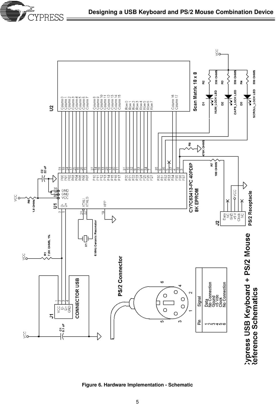
1 Designing a USB Keyboard and PS/2 Mouse Combination Device Using the Cypress Semiconductor CY7C6343 USB Microcontroller Introduction The Universal Serial Bus (USB) is an industry standard serial interface designed to connect computers to their peripherals. Devices such as keyboards, mice, joysticks, scanners, printers, and others can all benefit from the connectivity provided by USB. This application note describes how to design a USB keyboard and PS/2 mouse combination device using the Cypress Semiconductor single-chip CY7C6343 USB microcontroller. The PS/2 mouse is a widely used, low-cost pointing device found in computers today. By implementing a legacy PS/2 interface on the CY7C6343 USB microcontroller, originally targeted for USB keyboards, we provide a simple, low-cost solution for keyboard and mouse combination devices. This document starts with the basic operations of a USB keyboard and PS/2 mouse transfer protocol, followed by an introduction to the CY7C6343 USB controller. A schematic of the USB keyboard and PS/2 mouse combination device with its connection details can be found in the Hardware Implementation Section. The software section of this application note describes the architecture of the firmware required to implement the keyboard and PS/2 mouse interface functions. Several sample code segments are included to assist in the explanation. The source and binary code of the demonstration keyboard firmware is available free of charge from Cypress Semiconductor. Please contact your local Cypress sales office for details. Since this design is an extension of the USB keyboard design, it is assumed that the reader is familiar with the USB keyboard implementation. Therefore, this application note will only focus on other relevant issues such as PS/2 interface implementation and keyboard/mouse integration. If the reader is not familiar with the USB keyboard design, the application note titled Designing a USB Keyboard with the Cypress Semiconductor CY7C6343 USB Microcontroller is highly recommended. The above application note is available at the Cypress web site at This application note also assumes that the reader is familiar with the CY7C6343 USB controller and the Universal Serial Bus. The CY7C6343 data sheet is available from the Cypress web site. USB documentation can be found at the USB Implementers Forum web site at USB Keyboard Basics Key Switches and Scan Matrix A PS/2 keyboard has between 0 and 04 keys that are uniquely positioned in a scan matrix. The scan matrix consists of M rows and N columns, all of which are electrically isolated from each other. Typically, the number of rows (M) is no greater than 8, and the number of columns (N) is no greater than 20. Each key sits over two isolated contacts of its corresponding row and column in the scan matrix. When a key is pressed, the two contacts are shorted together, and the row and column of the key are electrically connected. USB Keyboard Controller A single CY7C6343 USB microcontroller is used to perform a variety of tasks, all of which help to cut down on the overall system overhead. Besides USB interface functions, the essential task of the microcontroller is to monitor the keys and report to the host computer whenever a key is pressed or released. The microcontroller writes a scan pattern out to the column lines consisting of all s and one 0, which is shifted through each column. The result is then read at the row lines. If a 0 is propagated to a row line, then the key at the intersection of that column and row has been pressed. See Figure. Row 0 Row Row 2 Row 3 Pattern 0 Pattern Pattern 2 Pattern 3 Column 0 Column 0 0 Column 2 Key Pressed Figure. Scan Matrix with Key, Pressed After scanning the key matrix and determining which key is pressed or released, the CY7C6343 microcontroller forms the keyboard data report and sends it to the host through a USB endpoint. For detailed implementation and operation of the USB keyboard, please refer to the application note Designing a USB Keyboard with the Cypress Semiconductor CY7C6343 USB Microcontroller. PS/2 Mouse Basics The IBM PS/2 mouse is a pointing device that uses a rubber track ball and two encoders to indicate X and Y movement to the host system. It also typically has two push-button switches. The mouse is connected to the host system via a 2.7 meter, shielded, 4-conductor cable, and a 6-pin connector. The four signals are: Data, Clock, +5Vdc and Ground. The signals and their pin assignments on the PS/2 connector are shown in the schematic in Figure 6. Column Result 0 Result Result 2 Result 3 0 Cypress Semiconductor Corporation 390 North First Street San Jose CA February 2, 998

2 Operation Modes The PS/2 mouse can operate in four different modes, shown below: Reset Mode: in this mode a self-test is initiated during power-on or by a Reset command. Upon successful completion of the self-test, a completion code (AAh) and an ID code (00h) are transmitted to the host system. Any commands sent before the transmission of the completion code and the ID byte are ignored. If the self-test fails, the mouse responds with a error code (FCh) and an ID code (00h), after which the mouse is disabled and awaits further commands from the host system. Stream Mode: in this mode a data report is only transmitted to the host system if a button is pressed or released or if at least one count of movement has been detected. The maximum rate of transfer is the programmed sample rate. Remote Mode: also known as polling mode. In this mode, a data report is transmitted only in response to a Read Data command. Wrap Mode: in this mode, any byte of data sent by the host system, except hexadecimal values ECh and FFh, is returned by the mouse. PS/2 Mouse Protocol and Commands The PS/2 mouse communicates with the host system through a defined protocol consisting of commands and responses. The ACK byte (FAh) is always the first response to any valid input received from the host system, except for Resend command and in Wrap mode. Table shows a list of all the valid commands. Table. PS/2 Mouse Commands Hex Code FF FE F6 F5 F4 F3 F2 F0 EE EC EB EA E9 E8 Command Reset Resend Set Default Disable Enable Set Sampling Rate Read Device Type Set Remote Mode Set Wrap Mode Reset Wrap Mode Read Data Set Stream Mode Status Request Set Resolution E7 Set Scaling 2: E6 Reset Scaling Only the mouse commands that are used in this design are discussed below. For complete description of the PS/2 mouse commands and operation, please see IBM Personal System/2 Mouse Technical Reference. from IBM (Document Number S68X ). The following are the commands used by this design and their brief descriptions: Reset: this command causes the mouse to enter the reset mode and do an internal self-test. Resend: any time the mouse receives an invalid command, it returns a Resend command to the host system. The host system, in turn, sends this command when it detects any error in any transmission from the mouse. When the mouse receives a Resend command, it retransmits the last packet of data sent. Set Stream Mode: this command sets the Stream mode. Enable: this command is used in the Stream mode to begin transmission. Disable: this command is used in the Stream mode to stop transmissions initiated by the mouse. The mouse responds to all other commands while disabled. If the mouse is in the Stream mode, it must be disabled before sending it any command that requires a response. Read Data: this command requests that all data defined in the data packet format be transmitted. This command is executed in either remote or stream mode. The data is transmitted even if there has been no movement since the last report or the switch status is unchanged. Mouse Data Report In the Stream mode, a data report is sent at the end of a sample interval if there has been a button event or mouse movement. The sampling rate is, by default, 00 reports per second, but it can be changed by the Set Sampling Rate command. On the other hand, in the Remote (or polling) mode, a data report is sent in response to a Read Data command. The data report is three bytes long and its format is shown in Table 2. Table 2. PS/2 Mouse Data Report Format Byte Bit Description 7 Y Data Overflow = Overflow 6 X Data Overflow = Overflow 5 Y Data Sign = Negative 4 X Data Sign = Negative 3 Reserved 2 Reserved Right Button Status = Pressed 0 Button Status = Pressed X Data Y Data Data Transmission Data transmission between the PS/2 mouse and the host system is carried out by 2 signals: Clock and Data. The Clock signal is used to clock serial data. The mouse generates the clocking signal when sending data to or receiving data from the host system. The host system requests the mouse to receive host data output by forcing the Data line LOW and allowing Clock to go HIGH. Figure 2 illustrates a PS/2 data frame containing a single byte of data. 2
 and an ID code (00h), after which the mouse is disabled and awaits further commands from the host system.")
3 Start Bit (Always = 0) Stop Bit (Always = ) Data Bit 0 Data Bit.... Data Odd Bit 7 Parity Figure 2. PS/2 Data Frame Format Communication is bidirectional using the Clock and Data signal lines. The signal for each of these lines comes from open collector devices, allowing either the mouse or the host system to drive a line LOW. During a non-transmission state, both Clock and Data lines are held HIGH. For detailed information on signaling protocol for data transmission using Clock and Data lines, please refer to IBM Personal System/2 Mouse Technical Reference. Introduction to CY7C6343 The CY7C6343 is a high performance 8-bit RISC microcontroller with an integrated USB Serial Interface Engine (SIE). The architecture implements 37 instructions that are optimized for USB applications. The CY7C6343 has a built-in clock oscillator and timers, as well as general purpose I/O lines that can be configured as inputs with internal pull-ups, open-drain outputs, or traditional CMOS outputs. High performance, low-cost human-interface type computer peripherals such as a keypad or keyboard can be implemented with a minimum of external components and firmware effort. Clock Circuit The CY7C6343 has a built-in clock oscillator and PLL-based frequency doubler. This circuit allows a cost-effective 6-MHz ceramic resonator to be used externally while the on-chip RISC core runs at 2 MHz. USB Serial Interface Engine (SIE) The operation of the SIE is totally transparent to the user. In the receive mode, USB packet decode and data transfer to the endpoint FIFO are automatically done by the SIE. The SIE then generates an interrupt to invoke a service routine after a packet is unpacked. In the transmit mode, data transfer from the endpoint and the assembly of the USB packet are handled automatically by the SIE. General Purpose I/O The CY7C6343 has 32 general purpose I/O lines divided into 4 ports: Port 0 through Port 3. One such I/O circuit is shown in Figure 3. Each port (8 bits) can be configured as inputs with internal pull-ups (7 Kohms), open drain outputs (high-impedance inputs), or traditional CMOS outputs. The port configuration is determined according to Table 3 below. Table 3. GPIO Configuration Port Configuration Bits Pin Interrupt Bit Driver mode Interrupt Polarity X Resistive 0 0 CMOS disabled Output 0 CMOS Input disabled 0 X Open Drain 00 X Open Drain + GPIO CFG mode 2-bits V CC Internal Data Bus Interrupt Enable Internal Buffer Data Out Latch Port Write Port Read Control Control Q 7 KΩ Q2 to Interrupt Controller Q3 ESD GPIO Pin Figure 3. One General Purpose I/O Line 3

4 Ports 0 to 2 offer low current drive with a typical current sink capability of 7 ma. Port 3 offers a higher current drive, with a typical current sink of 2 ma which can be used to drive LEDs. Each General Purpose I/O (GPIO) is capable of generating an interrupt to the RISC core. Interrupt polarity is selectable on a per port basis using the GPIO Configuration Register (see Table 3 above.) Selecting a negative polarity ( ) will cause falling edges to trigger an interrupt, while a positive polarity ( + ) selects rising edges as triggers. The interrupt triggered by a GPIO line is individually enabled by a dedicated bit in the Interrupt Enable Register. All GPIO interrupts are further masked by the Global GPIO Interrupt Enable Bit in the Global Interrupt Enable Register. The GPIO Configuration Register is located at I/O address 0x08. The Data Registers are located at I/O addresses 0x00 to 0x03 for Port 0 to Port 3 respectively. Power-up Mode The CY7C6343 offers 2 modes of operation after a power-on-reset (POR) event: suspend-on-reset (typical for a USB application) and run-on-reset (typical for a non-usb application). The suspend-on-reset mode is selected by attaching a pull-up resistor (00 to 470 KΩ) to V CC on Bit 7 of GPIO Port 3. The run-on-reset mode is selected by attaching a pull-down resistor (0 to 470 KΩ) to ground on Bit 7 of GPIO Port 3. See Figure 4. As the USB keyboard and PS/2 mouse combination device is a USB implementation, the CY7C6343 should be configured for suspend-on-reset. Port 2 is configured as resistive inputs (7 Kohm pull-ups to V CC ), and are connected to the M rows of the scan matrix (up to 8 rows are supported). Ports 0,, and 3 are configured as open drain outputs, and are used to connect to the N columns of the scan matrix, the 3 LEDs (Num Lock, Caps Lock, and Scroll Lock), and the two PS/2 mouse signals. Since the PS/2 signals occupy two bits of Port 3, we can only support keyboard scan matrices up to 8 columns. Most of the existing AT-0 or AT-04 type keyboards do not use more than 8 columns. For keyboards that use scan matrices with more than 8 columns, it is usually possible to relocate the keys from the columns 9 and greater to unassigned locations on columns 8 or below. The three LEDs are connected to the lower three bits of Port 3 as well (for high current drive). For scan matrices with less then 8 rows or 8 columns, the unused port bits should be left unconnected. The PS/2 signals are connected to the PS/2 mouse through a 6-pin PS/2 receptacle. +5V and GND are also available on the receptacle to power the PS/2 mouse. The strap option pull-up resistor R8 (470 KΩ) selects the Suspend-On-Reset mode for the USB microcontroller, and the series termination resistor R7 (00Ω) is used to reduce crosstalk problems over the PS/2 lines. During a keyboard scan test where no key is pressed, the row port data bits will be HIGH since all row lines are internally pulled up to V CC. When a key is pressed, driving its column port line LOW (key scan pattern) will cause its row line to go LOW as well. See Figure 5. 9&& 3RUW %LW 5SXOOXS 00. to WR470. KΩ2+0 Figure 4. (a) Suspend-On-Reset Mode Row Port Line Row i Column j Column Port Line 3RUW %LW Closed when key i,j is pressed Driven LOW by the key scan 5SXOOGRZQ WR. 2+0 Figure 4. (b) Run-On-Reset Mode Hardware Implementation Figure 6 is the schematic for a USB keyboard and PS/2 mouse combination device. This schematic is very similar to the one in the USB keyboard-only design. The major difference is the addition of the PS/2 mouse Clock and Data signal lines to the GPIO Port 3 bit 6 and bit 7, respectively. Figure 5. Row/Column Port Configuration A 6 MHz ceramic resonator is connected to the clock inputs of the microcontroller. This component should be placed as close to the microcontroller as possible. According to the USB specification, the USB D line of a low-speed device (.5 Mbps) should be tied to a voltage source between 3.0V and 3.6V with a.5 KΩ pull-up terminator. The CY7C6343 eliminates the need for a 3.3V regulator by specifying a 7.5-KΩ resistor connected between the USB D line and the nominal 5V V CC. This is compliant with Device Working Group Review Request 35. 4

5 Figure 6. Hardware Implementation - Schematic 5
6 Firmware Implementation USB Interface Like the USB keyboard-only device, the USB keyboard and PS/2 mouse combination device is also a USB Human Interface Device (HID). All USB HID-class devices follow the same USB start-up procedure. The procedure is shown in Figure 7. Device Plug-in (Power On Reset) Bus Reset Enumeration Data Acquisition/ Transfer Figure 7. USB Start-Up Procedure However, designing a USB HID combination device (keyboard and mouse functions) requires different approaches in phases such as USB enumeration and data acquisition/transfer. We will discuss these differences in the following sections. Device Plug-in and Bus Reset phases remain basically the same for the combination device as for the keyboard-only design. Enumeration A combination device follows the same usual USB enumeration process, where the device responds to the host with a number of USB descriptors. In this design, the combination device chooses to transmit both the keyboard and mouse data reports through a single interface, and over the same interrupt endpoint (endpoint ). This means that the HID report descriptor needs to be modified to describe both the keyboard and mouse data reports. All the other USB descriptors (device, configuration, interface, class, and endpoint descriptors) can remain the same as in the keyboard-only design. HID Report Descriptor The HID report descriptor is basically divided into two application collections, corresponding to the keyboard and the mouse collections. To allow the host system to distinguish different reports arriving over the same interrupt endpoint, a Report ID tag is added to each of the two reports. The Report ID value indicates the prefix added to a particular report. For example, the report descriptor defines a 3-byte mouse report with a report ID of 02. Therefore, whenever the combination device needs to send a mouse report in response to an IN packet on endpoint, it will generate a 4-byte data report, in which the first byte is the report ID 02. The keyboard report is assigned a report ID of 0. Example of HID Report Descriptor Usage Page (Generic Desktop) Usage (Keyboard) Collection (Application) ReportID (0x0) Usage Page (Key Codes) Usage Minimum (234) Usage Maximum (23) Logical Minimum (0) Logical Maximum () Report Size () Report Count (8) Input (Data,Variable,Absolute) Report Count () Report Size (8) Input (Constant);reserved byte Report Count (5);LED report Report Size () Usage Page (LEDs) Usage Minimum () Usage Maximum (5) Output (Data,Variable,Absolute) Report Count () Report Size (3) Output (Constant);3-bit padding Report Count (6) Report Size (8) Logical Minimum (0) Logical Maximum (0) Usage Page (Key Codes) Usage Minimum (0) Usage Maximum (0) Input (Data, Array);key array(6) End Collection Usage Page (Generic Desktop) Usage (Mouse) Collection (Application) ReportID (0x02) Usage (Pointer) Collection (Linked) Usage Page (Buttons) Usage Minimum () Usage Maximum (3) Logical Minimum (0) Logical Maximum () Report Count (3);three buttons Report Size () Input (Data,Variable,Absolute) Report Count () Report Size (5) Input (Constant);5-bit padding Usage Page (Generic Desktop) Usage (X) Usage (Y) Logical Minimum (-27) Logical Maximum (27) Report Size (8);X and Y data Report Count (2) Input (Data,Variable,Variable) End Collection End Collection 6

7 A more detailed description of HID and all the items used in an HID report descriptor can be found in the Device Class Definition for Human Interface Devices (HID) Revision.0. Data Acquisition/Transfer The firmware alternately scans the keyboard scan matrix and polls the PS/2 mouse to determine whether data reports need to be sent to the host system. As mentioned earlier, both the keyboard and mouse data reports are sent to the host using endpoint. When the firmware determines there is a key or many keys pressed, it sets up the keyboard data report, loads it into the endpoint FIFO, and enables the endpoint transmission. Then the keyboard data report will be sent when the next IN packet is received on the endpoint from the host. The PS/2 mouse follows the same steps to send its data report to the host. The HID keyboard data report is 8 bytes long, and consists of one byte of modifiers plus 7 key scan code bytes. Table 4 shows the format of the keyboard report. Usage codes for each key can be found in Appendix A.3 of the Device Class Definition for Human Interface Devices (HID). Since the maximum data packet size of an interrupt pipe for a low-speed USB device is limited to 8 bytes, the device needs to send the complete report (-byte report ID plus 8-byte data report) in two interrupt transactions, instead of only one in the keyboard-only design. In the first interrupt transaction, a report ID and the first 7 bytes of the data report are sent in response to a IN token. In the second transaction, a report ID and the last byte of the data report are sent in response to the following IN token. When any LED keys (i.e., Num Lock, Caps Lock, Scroll Lock) are pressed or released, the host system issues a SETUP packet with a Set_Report request through the control pipe to End Point 0, followed by an OUT packet with 2 data bytes. The first byte corresponds to the report ID and the second byte indicates which LED should be on or off (see Table 5.) Table 4. USB Keyboard Data Report Format Byte b7 b6 b5 b4 b3 b2 b b0 0 Modifiers Right GUI Right Alt Reserved 2 Key scan code 3 key 2 scan code 4 Key 3 scan code 5 Key 4 scan code 6 Key 5 scan code 7 Key 6 scan code Right Shift Right Ctrl GUI Alt Shift Ctrl Table 5. USB Keyboard Set_Report Data Format for LED Byte b7 b6 b5 b4 b3 b2 b b0 0 Constanstanstanpose Con- Con- Kana Com- Scroll Caps Num LED Report Lock Lock Lock The HID mouse data report is 3 bytes long (see Table 6). The firmware polls the PS/2 mouse and obtains the PS/2 mouse data packet (see Table 2). Then it extracts the button and X, Y movement information from the PS/2 data packet to compose the HID mouse data report. Different from the keyboard report, the complete mouse report can be sent in a single USB interrupt transaction since it is only 4 bytes long ( byte of report ID and 3 bytes of mouse data). The byte order and bit field positions for both the keyboard and mouse reports are consistent with the Boot Protocol requirements for legacy systems. Table 6. USB Mouse Data Report Format Byte b7 b6 b5 b4 b3 b2 b b0 0 Padding Alt Horizontal (X) Displacement 2 Vertical (Y) Displacement Shift Button PS/2 Interface State Machine Implementation The USB keyboard and PS/2 mouse combination device firmware is an extension of the keyboard-only firmware, with the addition of PS/2 interface code and changes to allow functional integration. The PS/2 interface code consists of a number of subroutines which can be called by the main code to perform PS/2 related tasks. In this application note, we will mainly discuss the principle of operation and how to utilize these subroutines to operate a PS/2 mouse. For implementation details of the subroutines, please refer to the firmware source code. The PS/2 mouse interface code is implemented by two state machines: mouse_int and mouse_machine. The former operates at the bit/byte transaction level and the latter operates at the byte/command transaction level. The mouse_int state machine manages the transmission and reception of data bytes over the PS/2 bus. Since the PS/2 mouse always drives the clock signal connected to a GPIO pin, the mouse_int state machine is driven by GPIO interrupts generated from the falling edge of the PS/2 clock. In the GPIO interrupt service routine, the microcontroller will either read from or write to the PS/2 data line, depending on whether it is receiving data from or sending data to the PS/2 mouse. The states of mouse_int corresponds to bit states of a PS/2 byte transmission or reception (i.e., start bit, data bits, parity and stop bit). The mouse_int is initiated either by a byte transmission request from the high-level state machine, mouse_machine, or by the start of a new receive byte from the mouse. Upon completion of a byte transfer (normal or otherwise) by mouse_int, the PS/2 bus is inhibited (by holding 7

8 the clock line LOW) to allow the high-level state machine, mouse_machine, to act. The high-level state machine (mouse_machine) is, in turn, driven by periodic calls from the application (the keyboard and PS/2 mouse firmware in this case). Whenever we initiate a mouse command, mouse_machine must be called regularly from the application in order to process its state sequences. Making these regular calls to mouse_machine is referred to as operating the mouse_machine. Every call to mouse_machine returns an idle/busy indication in the microcontroller s C-bit (carry). It returns C-bit = 0 if it is idle (i.e., no mouse commands are currently in process), and C-bit = if a mouse command is currently being processed. No new mouse command should be initiated by the application unless mouse_machine is idle. Further, mouse_machine can only be made busy by a command initiated by the application or a power-up reset. A sample code in Figure 8 shows how to initiate a mouse command and operate mouse_machine. Call to mouse_poll initiates the Read Data command to the mouse, and sets the mouse_machine to the corresponding state. The subsequent loop calls mouse_machine to sequence through the states until the C-bit = 0, indicating the state machine is done and idle. MouseTask: call mouse_poll ;send poll cmd tw3: call mouse_machine ;wait until done jc tw3 ;jump back if C= Figure 8. Operating mouse_machine PS/2 Support Subroutines A number of support subroutines are provided to facilitate the operation of the PS/2 mouse. The main firmware code calls these subroutines to initialize, set operation mode and read data from the PS/2 mouse. Their descriptions and usages are as follows: ps2_init: this subroutine initializes the PS/2 mouse port. It must be called from the main code within 500 ms of power-up, before the PS/2 mouse starts transmitting. Upon application of power and completion of its self-diagnostics, the mouse will automatically transmit a two-byte initialization pattern (0xAA and 0x00). Regular calls to mouse_machine must be made after the call to ps2_init until it returns idle, indicating the transmission of the initialization pattern is complete. The receipt of the pattern recognizes that the mouse is attached to the device. mouse_reset: this subroutine initiates a Reset command to the mouse, causing it to execute its self-diagnostics and return the initialization pattern. After a call to mouse_reset, mouse_machine must be operated until it returns idle. In this instance, the returned data from a properly functioning mouse will be a three-byte string (0xFA, 0xAA, and 0x00). The first byte is the ACK byte to the Reset command, and the next two bytes are the initialization pattern. Note that the initialization pattern will only be transmitted automatically by the mouse at power-up. Therefore, if the USB microcontroller gets reset by some reason, it is recommended that mouse_reset be called to duplicate the reset/initialization sequence, in order to make sure that the firmware recognizes the mouse is attached. ps2_status(): this subroutine can be called once mouse_machine goes idle after the reset/initialization sequence to determine if a mouse is attached. It returns 0 in the accumulator (register A) if no mouse is attached; otherwise, is returned. mouse_init: Once the mouse has gone through the reset/initialization phase and is detected as a result, mouse_init must be invoked by the main code to prepare the mouse for data polling. This is done by sending the Set Remote Mode and Enable commands to the mouse. Mouse_init operates the mouse_machine through the command sending transactions, and only returns when the mouse is properly configured. Mouse_init is also used to reinitialize the mouse upon leaving the suspend mode. Suspend/resume and remote wakeup issues will be discussed in the next section. mouse_poll: Upon successful completion of mouse_init, data may be polled from the mouse by calling the mouse_poll subroutine. Note that mouse_poll merely initiates the transaction, which is then driven to completion by operating mouse_machine until it returns idle. When the transaction is completed, the 3-byte PS/2 mouse data report will be available in RAM area at address mouse_packetv. mouse_suspend: this subroutine is called before the microcontroller enters suspend state. It initiates a Set Stream Mode command and operates mouse_machine until the transaction is complete. Keyboard and Mouse Firmware Integration Main Loop The main loop of the firmware (Figure 9) runs two tasks continuously: ScanTask and MouseTask. The ScanTask is the same keyboard task in the keyboard-only firmware. It scans the keyboard scan matrix to determine any key status change, loads the keyboard report to endpoint FIFO and Main Loop ScanTask MouseTask 20 ms Delay Figure 9. Main Loop 8
.")
9 sends it to the host system if necessary. For more details on its operation please see the USB keyboard application note. Similarly, the MouseTask calls mouse_poll subroutine to read data from the PS/2 mouse, copies the mouse report from memory buffer to endpoint FIFO and transmits it to the host system. An arbitrary delay of 20 ms was added before the code loops back. This is to make sure that the PS/2 mouse gets ready to respond to the next polling command. USB Suspend/Resume and Remote Wakeup According to the USB Specification.0, a device has to go into suspend mode after 3 ms of no bus activity. The ms ISR determines when this condition occurs (by reading the Bus Activity bit, bit 3, of the USB Status and Control Register, Fh) and suspends the microcontroller. This is accomplished by setting bit 0 (Run bit) and bit 3 (Suspend bit) of the Processor Status and Control Register (FFh). The microcontroller will resume operation upon one of the following three events: USB bus activity, keyboard activity, or PS/2 mouse activity. USB bus activity resume is carried out automatically by the microcontroller. On the other hand, keyboard and PS/2 mouse activity during suspend are detected through GPIO interrupts. For this reason, before entering suspend, GPIO interrupts for the keyboard and mouse must be properly enabled. For the keyboard, prior to suspending the microcontroller, the ms ISR pulls down all the column port lines and enable a falling edge interrupt on all Port 2 lines (Row port). If any key is pressed while in suspended state, one of the row lines will be pulled LOW and trigger a GPIO interrupt. The GPIO ISR will then send a resume signal (force a K state where D+ is HIGH and D is LOW for 0 ms) to wake up the host system (remote wake up). The PS/2 mouse normally operates in Remote (polling) mode, where the mouse only transmits a data report in response to a Read Data command. When the microcontroller enters suspend state, however, it no longer polls the mouse for data. Thus, it is desirable to allow the mouse to be capable of autonomously waking up the microcontroller if it has data to transmit (mouse movement or button press). This is accomplished by placing the mouse in Stream mode before entering suspend. In the Stream mode, the PS/2 mouse will transmit data at regular intervals any time it has new data available, generating GPIO interrupts and waking up the microcontroller. Before entering suspend the main code must call function mouse_suspend, which initiates a Set Stream Mode command and operates mouse_machine until the transaction is complete. Then the main code will enable suspend, leaving the Port 3 GPIO interrupt enabled. During suspend state, any activity on the PS/2 port will cause an entry to the GPIO ISR, which will immediately inhibit the mouse transmission. During the wakeup sequence, the firmware must also call mouse_init to place the mouse back to Remote mode for normal data polling operations. GPIO Interrupt Service Routine In the keyboard-only firmware, the GPIO ISR was only used to handle the keyboard resume and the sending of the remote wakeup signal after leaving the suspend state. For the keyboard and mouse combination device, however, the GPIO interrupt is also used to drive the PS/2 low-level state machine (mouse_int) at each falling edge of the PS/2 clock signal. No Bus Still Idle? Yes Send Remote Wakeup Signal GPIO ISR In Suspend Mode? Return Yes Call Mouse Bit/byte Level State Machine mouse_int Figure 0. GPIO Interrupt Service Routine Upon entering the GPIO ISR (See Figure 0), a test is done to determine whether the firmware is running in normal operation mode or has just left suspend mode. If it is in normal operation, the mouse_int state machine is called; otherwise, the remote wakeup sequence begins. -ms Interrupt Service Routine For the keyboard and mouse combination firmware, a few changes were added to the keyboard-only ms ISR (Figure ): The keyboard scan task is no longer scheduled every 4 ms as in the keyboard-only firmware. Before entering suspend state, the PS/2 mouse is placed in Stream mode. Also, after coming out of suspend, the mouse is set back to Remote mode. The PS/2 mouse time-out counter increment and check is included. If the PS/2 is in the active state for more than 25 ms and no transfer happens, a time-out condition will occur, resetting the PS/2 bus and setting the state machines to idle. PS/2 Signal Timing Issue For reliable PS/2 bus operation, the GPIO interrupt service provided by the main code must ensure that the latency between a falling edge on the PS/2 clock line and resultant entry into the bit/byte level state machine (mouse_int) is no more than 7 µs. This requirement precludes the disabling of interrupts for long periods of time by other code modules, while mouse_machine is busy. Special attention should be given to the ms ISR or other ISRs that may disable interrupt for long periods of time. No 9

10 Conclusion The two main enabling factors of the proliferation of the USB devices are cost and functionality. The CY7C6343 meets both requirements by integrating the USB SIE and multi-function I/Os with a USB optimized RISC core in a low-cost part. In this application note, the CY7C6343 USB microcontroller is used to implement a USB keyboard and PS/2 mouse combination device. The PS/2 interface, fully implemented in firmware, preserves the use of a legacy PS/2 mouse without any additional cost. ms ISR Clear Watchdog Timer 3 ms of bus inactivity? No Yes Save GPIO Port Settings Write 0 to Keyboard Column Port Bits Enable GPIO Interrupt on Port 2 and 3 Set the PS/2 Mouse to Stream Mode Go Suspend RESUME Restore GPIO Port Settings Disable GPIO Interrupt on Port 2 Has 2 ms past? Yes Keyboard Debounce FIFO increment No Restore PS/2 Mouse to Remote Mode PS/2 Mouse Timeout Check Return Figure. ms Interrupt Service Routine PS/2 is a registered trademark of the International Business Machines Corp. Cypress Semiconductor Corporation, 998. The information contained herein is subject to change without notice. Cypress Semiconductor Corporation assumes no responsibility for the use of any circuitry other than circuitry embodied in a Cypress Semiconductor product. Nor does it convey or imply any license under patent or other rights. Cypress Semiconductor does not authorize its products for use as critical components in life-support systems where a malfunction or failure may reasonably be expected to result in significant injury to the user. The inclusion of Cypress Semiconductor products in life-support systems application implies that the manufacturer assumes all risk of such use and in doing so indemnifies Cypress Semiconductor against all charges.

Microcontroller Based Low Cost Portable PC Mouse and Keyboard Tester
 Leonardo Journal of Sciences ISSN 1583-0233 Issue 20, January-June 2012 p. 31-36 Microcontroller Based Low Cost Portable PC Mouse and Keyboard Tester Ganesh Sunil NHIVEKAR *, and Ravidra Ramchandra MUDHOLKAR
8-bit Microcontroller. Application Note. AVR415: RC5 IR Remote Control Transmitter. Features. Introduction. Figure 1.
 AVR415: RC5 IR Remote Control Transmitter Features Utilizes ATtiny28 Special HW Modulator and High Current Drive Pin Size Efficient Code, Leaves Room for Large User Code Low Power Consumption through Intensive
HANDLING SUSPEND MODE ON A USB MOUSE
 APPLICATION NOTE HANDLING SUSPEND MODE ON A USB MOUSE by Microcontroller Division Application Team INTRODUCTION All USB devices must support Suspend mode. Suspend mode enables the devices to enter low-power
User Manual. AS-Interface Programmer
 AS-Interface Programmer Notice: RESTRICTIONS THE ZMD AS-INTERFACE PROGRAMMER HARDWARE AND ZMD AS-INTERFACE PROGRAMMER SOFTWARE IS DESIGNED FOR IC EVALUATION, LABORATORY SETUP AND MODULE DEVELOPMENT ONLY.
Appendix C: Keyboard Scan Codes
 Thi d t t d ith F M k 4 0 2 Appendix C: Keyboard Scan Codes Table 90: PC Keyboard Scan Codes (in hex) Key Down Up Key Down Up Key Down Up Key Down Up Esc 1 81 [ { 1A 9A, < 33 B3 center 4C CC 1! 2 82 ]
An Analysis of Wireless Device Implementations on Universal Serial Bus
 An Analysis of Wireless Device Implementations on Universal Serial Bus 6/3/97 Abstract Universal Serial Bus (USB) is a new personal computer (PC) interconnect that can support simultaneous attachment of
Develop a Dallas 1-Wire Master Using the Z8F1680 Series of MCUs
 Develop a Dallas 1-Wire Master Using the Z8F1680 Series of MCUs AN033101-0412 Abstract This describes how to interface the Dallas 1-Wire bus with Zilog s Z8F1680 Series of MCUs as master devices. The Z8F0880,
Old Company Name in Catalogs and Other Documents
 To our customers, Old Company Name in Catalogs and Other Documents On April 1 st, 2010, NEC Electronics Corporation merged with Renesas Technology Corporation, and Renesas Electronics Corporation took
8-Bit Flash Microcontroller for Smart Cards. AT89SCXXXXA Summary. Features. Description. Complete datasheet available under NDA
 Features Compatible with MCS-51 products On-chip Flash Program Memory Endurance: 1,000 Write/Erase Cycles On-chip EEPROM Data Memory Endurance: 100,000 Write/Erase Cycles 512 x 8-bit RAM ISO 7816 I/O Port
AVR151: Setup and Use of the SPI. Introduction. Features. Atmel AVR 8-bit Microcontroller APPLICATION NOTE
 Atmel AVR 8-bit Microcontroller AVR151: Setup and Use of the SPI APPLICATION NOTE Introduction This application note describes how to set up and use the on-chip Serial Peripheral Interface (SPI) of the
Project 4: Pseudo USB Simulation Introduction to UNIVERSAL SERIAL BUS (USB) STANDARD
 STANDARD") Project 4: Pseudo USB Simulation Introduction to UNIVERSAL SERIAL BUS (USB) STANDARD The Universal Serial Bus is a fast, bi-directional, low cost, dynamically attachable serial interface. The motivation
Project 4: Pseudo USB Simulation Introduction to UNIVERSAL SERIAL BUS (USB) STANDARD The Universal Serial Bus is a fast, bi-directional, low cost, dynamically attachable serial interface. The motivation
Hello, and welcome to this presentation of the STM32 SDMMC controller module. It covers the main features of the controller which is used to connect
 Hello, and welcome to this presentation of the STM32 SDMMC controller module. It covers the main features of the controller which is used to connect the CPU to an SD card, MMC card, or an SDIO device.
8051 MICROCONTROLLER COURSE
 8051 MICROCONTROLLER COURSE Objective: 1. Familiarization with different types of Microcontroller 2. To know 8051 microcontroller in detail 3. Programming and Interfacing 8051 microcontroller Prerequisites:
AN141 SMBUS COMMUNICATION FOR SMALL FORM FACTOR DEVICE FAMILIES. 1. Introduction. 2. Overview of the SMBus Specification. 2.1.
 SMBUS COMMUNICATION FOR SMALL FORM FACTOR DEVICE FAMILIES 1. Introduction C8051F3xx and C8051F41x devices are equipped with an SMBus serial I/O peripheral that is compliant with both the System Management
Allows the user to protect against inadvertent write operations. Device select and address bytes are Acknowledged Data Bytes are not Acknowledged
 Write Protect CAT24WCxxx I 2 C Serial EEPROMs. Allows the user to protect against inadvertent write operations. WP = V CC : Write Protected Device select and address bytes are Acknowledged Data Bytes are
Bluetooth HID Profile
 RN-WIFLYCR-UM-.01 RN-HID-UM Bluetooth HID Profile 2012 Roving Networks. All rights reserved. Version 1.0r 1/17/2012 USER MANUAL www.rovingnetworks.com 1 OVERVIEW Roving Networks Bluetooth modules support
ARM Thumb Microcontrollers. Application Note. Software ISO 7816 I/O Line Implementation. Features. Introduction
 Software ISO 7816 I/O Line Implementation Features ISO 7816-3 compliant (direct convention) Byte reception and transmission with parity check Retransmission on error detection Automatic reception at the
150127-Microprocessor & Assembly Language
 Chapter 3 Z80 Microprocessor Architecture The Z 80 is one of the most talented 8 bit microprocessors, and many microprocessor-based systems are designed around the Z80. The Z80 microprocessor needs an
USB2.0 <=> I2C V4.4. Konverter Kabel und Box mit Galvanischetrennung
 USB2.0 I2C V4.4 Konverter Kabel und Box mit Galvanischetrennung USB 2.0 I2C Konverter Kabel V4.4 (Prod. Nr. #210) USB Modul: Nach USB Spezifikation 2.0 & 1.1 Unterstützt automatisch "handshake
The I2C Bus. NXP Semiconductors: UM10204 I2C-bus specification and user manual. 14.10.2010 HAW - Arduino 1
 The I2C Bus Introduction The I2C-bus is a de facto world standard that is now implemented in over 1000 different ICs manufactured by more than 50 companies. Additionally, the versatile I2C-bus is used
Data Acquisition Module with I2C interface «I2C-FLEXEL» User s Guide
 Data Acquisition Module with I2C interface «I2C-FLEXEL» User s Guide Sensors LCD Real Time Clock/ Calendar DC Motors Buzzer LED dimming Relay control I2C-FLEXEL PS2 Keyboards Servo Motors IR Remote Control
MICROPROCESSOR AND MICROCOMPUTER BASICS
 Introduction MICROPROCESSOR AND MICROCOMPUTER BASICS At present there are many types and sizes of computers available. These computers are designed and constructed based on digital and Integrated Circuit
Learning USB by Doing. John.Hyde@intel.com
 Learning USB by Doing. John.Hyde@intel.com The question that I am asked most often is how do I start a USB project? There are many alternate starting points for the design of a USB I/O device and this
Application Note. 8-bit Microcontrollers. AVR270: USB Mouse Demonstration
 AVR270: USB Mouse Demonstration Features Runs with AT90USB Microcontrollers at 8MHz USB Low Power Bus Powered Device (less then 100mA) Supported by any PC running Windows (98SE or later), Linux or Mac
Serial Communications
 Serial Communications 1 Serial Communication Introduction Serial communication buses Asynchronous and synchronous communication UART block diagram UART clock requirements Programming the UARTs Operation
Implementing SPI Master and Slave Functionality Using the Z8 Encore! F083A
 Application Note Implementing SPI Master and Slave Functionality Using the Z8 Encore! F083A AN026701-0308 Abstract This application note demonstrates a method of implementing the Serial Peripheral Interface
Below is a diagram explaining the data packet and the timing related to the mouse clock while receiving a byte from the PS-2 mouse:
 PS-2 Mouse: The Protocol: For out mini project we designed a serial port transmitter receiver, which uses the Baud rate protocol. The PS-2 port is similar to the serial port (performs the function of transmitting
MBP_MSTR: Modbus Plus Master 12
 Unity Pro MBP_MSTR 33002527 07/2011 MBP_MSTR: Modbus Plus Master 12 Introduction This chapter describes the MBP_MSTR block. What s in this Chapter? This chapter contains the following topics: Topic Page
INPUT/OUTPUT ORGANIZATION
 INPUT/OUTPUT ORGANIZATION Accessing I/O Devices I/O interface Input/output mechanism Memory-mapped I/O Programmed I/O Interrupts Direct Memory Access Buses Synchronous Bus Asynchronous Bus I/O in CO and
USER GUIDE EDBG. Description
 USER GUIDE EDBG Description The Atmel Embedded Debugger (EDBG) is an onboard debugger for integration into development kits with Atmel MCUs. In addition to programming and debugging support through Atmel
HD44780U (LCD-II) (Dot Matrix Liquid Crystal Display Controller/Driver)
 (Dot Matrix Liquid Crystal Display Controller/Driver)") HD4478U (LCD-II) (Dot Matrix Liquid Crystal Display Controller/Driver) Description The HD4478U dot-matrix liquid crystal display controller and driver LSI displays alphanumerics, Japanese kana characters,
HD4478U (LCD-II) (Dot Matrix Liquid Crystal Display Controller/Driver) Description The HD4478U dot-matrix liquid crystal display controller and driver LSI displays alphanumerics, Japanese kana characters,
M68EVB908QL4 Development Board for Motorola MC68HC908QL4
 M68EVB908QL4 Development Board for Motorola MC68HC908QL4! Axiom Manufacturing 2813 Industrial Lane Garland, TX 75041 Email: Sales@axman.com Web: http://www.axman.com! CONTENTS CAUTIONARY NOTES...3 TERMINOLOGY...3
DS1621 Digital Thermometer and Thermostat
 Digital Thermometer and Thermostat www.dalsemi.com FEATURES Temperature measurements require no external components Measures temperatures from 55 C to +125 C in 0.5 C increments. Fahrenheit equivalent
(Cat. No. 6008-SI) Product Data
 Product Data") (Cat. No. 6008-SI) Product Data 1 Because of the variety of uses for this product and because of the differences between solid state products and electromechanical products, those responsible for applying
(Cat. No. 6008-SI) Product Data 1 Because of the variety of uses for this product and because of the differences between solid state products and electromechanical products, those responsible for applying
Quick Installation. A Series of Intelligent Bar Code Reader with NeuroFuzzy Decoding. Quick Installation
 Quick Installation A Series of Intelligent Bar Code Reader with NeuroFuzzy Decoding This chapter intends to get your new FuzzyScan scanner working with your existing system within minutes. General instructions
STEPPER MOTOR SPEED AND POSITION CONTROL
 STEPPER MOTOR SPEED AND POSITION CONTROL Group 8: Subash Anigandla Hemanth Rachakonda Bala Subramanyam Yannam Sri Divya Krovvidi Instructor: Dr. Jens - Peter Kaps ECE 511 Microprocessors Fall Semester
AT89C5131A Starter Kit... Software User Guide
 AT89C5131A Starter Kit... Software User Guide Table of Contents Section 1 Introduction... 1-1 1.1 Abbreviations...1-1 Section 2 Getting Started... 2-3 2.1 Hardware Requirements...2-3 2.2 Software Requirements...2-3
Application Note AN_209. AN_209 PDIUSBD12 to FT120 Migration Guide
 AN_209 AN_209 PDIUSBD12 to FT120 Migration Guide Issue Date: 2012-12-14 The FT120 is a cost and feature optimized USB Full-Speed device controller. It communicates with a micro-controller over a generic
PACKAGE OUTLINE DALLAS DS2434 DS2434 GND. PR 35 PACKAGE See Mech. Drawings Section
 PRELIMINARY DS2434 Battery Identification Chip FEATURES Provides unique ID number to battery packs PACKAGE OUTLINE Eliminates thermistors by sensing battery temperature on chip DALLAS DS2434 1 2 3 256
GPS/GLONASS SiRFstarV Evaluation Kit EVA5100-A
 GPS/GLONASS SiRFstarV Evaluation Kit EVA5100-A A Description of the Evaluation Board for Maestro s GPS/GLONASS Receiver Module A5100-A User s Manual Version 0.1 Revision History Rev. Date Description 0.1
CHAPTER 11: Flip Flops
 CHAPTER 11: Flip Flops In this chapter, you will be building the part of the circuit that controls the command sequencing. The required circuit must operate the counter and the memory chip. When the teach
Part Number Description Packages available
 Features 3 digital I/O Serial Data output Connects directly to RF Modules Easy Enc / Dec Pairing Function Minimal External Components Required Performs all encoding/decoding of data for Reliable Operation.
BLUETOOTH SERIAL PORT PROFILE. iwrap APPLICATION NOTE
 BLUETOOTH SERIAL PORT PROFILE iwrap APPLICATION NOTE Thursday, 19 April 2012 Version 1.2 Copyright 2000-2012 Bluegiga Technologies All rights reserved. Bluegiga Technologies assumes no responsibility for
1-Mbit (128K x 8) Static RAM
 Static RAM") 1-Mbit (128K x 8) Static RAM Features Pin- and function-compatible with CY7C109B/CY7C1009B High speed t AA = 10 ns Low active power I CC = 80 ma @ 10 ns Low CMOS standby power I SB2 = 3 ma 2.0V Data Retention
1-Mbit (128K x 8) Static RAM Features Pin- and function-compatible with CY7C109B/CY7C1009B High speed t AA = 10 ns Low active power I CC = 80 ma @ 10 ns Low CMOS standby power I SB2 = 3 ma 2.0V Data Retention
MICROPROCESSOR. Exclusive for IACE Students www.iace.co.in iacehyd.blogspot.in Ph: 9700077455/422 Page 1
 MICROPROCESSOR A microprocessor incorporates the functions of a computer s central processing unit (CPU) on a single Integrated (IC), or at most a few integrated circuit. It is a multipurpose, programmable
How To Use A Watt Saver On A Microcontroller (Watt Saver) On A Cell Phone Or Mp3 Player
 On A Cell Phone Or Mp3 Player") Watt Saver for a Cell Phone AC Adapter Reference Design Document Number: DRM130 Rev 1, 10/2013 2 Freescale Semiconductor, Inc. Contents Section number Title Page Chapter 1 Introduction 1.1 Overview...5
Watt Saver for a Cell Phone AC Adapter Reference Design Document Number: DRM130 Rev 1, 10/2013 2 Freescale Semiconductor, Inc. Contents Section number Title Page Chapter 1 Introduction 1.1 Overview...5
Secure My-d TM and Mifare TM RFID reader system by using a security access module Erich Englbrecht (info@eonline.de) V0.1draft
 V0.1draft") Application Report Secure My-d TM and Mifare TM RFID reader system by using a security access module Erich Englbrecht (info@eonline.de) V0.1draft Embedded RF ABSTRACT This application report describes
Application Report Secure My-d TM and Mifare TM RFID reader system by using a security access module Erich Englbrecht (info@eonline.de) V0.1draft Embedded RF ABSTRACT This application report describes
Microtronics technologies Mobile: 99707 90092
 For more Project details visit: http://www.projectsof8051.com/rfid-based-attendance-management-system/ Code Project Title 1500 RFid Based Attendance System Synopsis for RFid Based Attendance System 1.
MACHINE ARCHITECTURE & LANGUAGE
 in the name of God the compassionate, the merciful notes on MACHINE ARCHITECTURE & LANGUAGE compiled by Jumong Chap. 9 Microprocessor Fundamentals A system designer should consider a microprocessor-based
M25P05-A. 512-Kbit, serial flash memory, 50 MHz SPI bus interface. Features
 512-Kbit, serial flash memory, 50 MHz SPI bus interface Features 512 Kbits of flash memory Page program (up to 256 bytes) in 1.4 ms (typical) Sector erase (256 Kbits) in 0.65 s (typical) Bulk erase (512
Atmel AVR4903: ASF - USB Device HID Mouse Application. Atmel Microcontrollers. Application Note. Features. 1 Introduction
 Atmel AVR4903: ASF - USB Device HID Mouse Application Features USB 2.0 compliance - Chapter 9 compliance - HID compliance - Low-speed (1.5Mb/s) and full-speed (12Mb/s) data rates Standard USB HID mouse
4 Character 5x7 LED Matrix Display
 Mini project report on 4 Character 5x7 LED Matrix Display Submitted by Agarwal Vikas, MTech II, CEDT K.Sreenivasulu M.E (Micro) II, CEDT CENTRE FOR ELECTRONICS DESIGN AND TECHNOLOGY INDIAN INSTITUTE OF
DEPARTMENT OF COMPUTER SCIENCE & ENGINEERING Question Bank Subject Name: EC6504 - Microprocessor & Microcontroller Year/Sem : II/IV
 DEPARTMENT OF COMPUTER SCIENCE & ENGINEERING Question Bank Subject Name: EC6504 - Microprocessor & Microcontroller Year/Sem : II/IV UNIT I THE 8086 MICROPROCESSOR 1. What is the purpose of segment registers
FM75 Low-Voltage Two-Wire Digital Temperature Sensor with Thermal Alarm
 Low-Voltage Two-Wire Digital Temperature Sensor with Thermal Alarm Features User Configurable to 9, 10, 11 or 12-bit Resolution Precision Calibrated to ±1 C, 0 C to 100 C Typical Temperature Range: -40
NTE2053 Integrated Circuit 8 Bit MPU Compatible A/D Converter
 NTE2053 Integrated Circuit 8 Bit MPU Compatible A/D Converter Description: The NTE2053 is a CMOS 8 bit successive approximation Analog to Digital converter in a 20 Lead DIP type package which uses a differential
DS1621 Digital Thermometer and Thermostat
 www.maxim-ic.com FEATURES Temperature measurements require no external components Measures temperatures from -55 C to +125 C in 0.5 C increments. Fahrenheit equivalent is -67 F to 257 F in 0.9 F increments
MicroMag3 3-Axis Magnetic Sensor Module
 1008121 R01 April 2005 MicroMag3 3-Axis Magnetic Sensor Module General Description The MicroMag3 is an integrated 3-axis magnetic field sensing module designed to aid in evaluation and prototyping of PNI
AN10850. LPC1700 timer triggered memory to GPIO data transfer. Document information. LPC1700, GPIO, DMA, Timer0, Sleep Mode
 LPC1700 timer triggered memory to GPIO data transfer Rev. 01 16 July 2009 Application note Document information Info Keywords Abstract Content LPC1700, GPIO, DMA, Timer0, Sleep Mode This application note
8-bit Microcontroller. Application Note. AVR134: Real-Time Clock (RTC) using the Asynchronous Timer. Features. Theory of Operation.
 using the Asynchronous Timer. Features. Theory of Operation.") AVR134: Real-Time Clock (RTC) using the Asynchronous Timer Features Real-Time Clock with Very Low Power Consumption (4µA @ 3.3V) Very Low Cost Solution Adjustable Prescaler to Adjust Precision Counts Time,
AVR134: Real-Time Clock (RTC) using the Asynchronous Timer Features Real-Time Clock with Very Low Power Consumption (4µA @ 3.3V) Very Low Cost Solution Adjustable Prescaler to Adjust Precision Counts Time,
DeviceNet Communication Manual
 DeviceNet Communication Manual Soft-Starter Series: SSW-07/SSW-08 Language: English Document: 10000046963 / 00 03/2008 Summary ABOUT THIS MANUAL... 5 ABBREVIATIONS AND DEFINITIONS... 5 NUMERICAL REPRESENTATION...
UMBC. ISA is the oldest of all these and today s computers still have a ISA bus interface. in form of an ISA slot (connection) on the main board.
 on the main board.") Bus Interfaces Different types of buses: ISA (Industry Standard Architecture) EISA (Extended ISA) VESA (Video Electronics Standards Association, VL Bus) PCI (Periheral Component Interconnect) USB (Universal
Bus Interfaces Different types of buses: ISA (Industry Standard Architecture) EISA (Extended ISA) VESA (Video Electronics Standards Association, VL Bus) PCI (Periheral Component Interconnect) USB (Universal
Atmel AVR4920: ASF - USB Device Stack - Compliance and Performance Figures. Atmel Microcontrollers. Application Note. Features.
 Atmel AVR4920: ASF - USB Device Stack - Compliance and Performance Figures Features Compliance to USB 2.0 - Chapters 8 and 9 - Classes: HID, MSC, CDC, PHDC Interoperability: OS, classes, self- and bus-powered
PART B QUESTIONS AND ANSWERS UNIT I
 PART B QUESTIONS AND ANSWERS UNIT I 1. Explain the architecture of 8085 microprocessor? Logic pin out of 8085 microprocessor Address bus: unidirectional bus, used as high order bus Data bus: bi-directional
DS1721 2-Wire Digital Thermometer and Thermostat
 www.dalsemi.com FEATURES Temperature measurements require no external components with ±1 C accuracy Measures temperatures from -55 C to +125 C; Fahrenheit equivalent is -67 F to +257 F Temperature resolution
AN2358. Manchester Decoder Using PSoC 1. Introduction. Contents. Manchester Code Principle
 AN2358 Author: Philippe Larcher Associated Project: Yes Associated Part Family: CY8C29x66, CY8C27x43, CY8C24X94, CY8C24x23A, CY8C23x33, CY8C21x34, CY8C21x23 Software Version: PSoC Designer 5.4 Related
PS/2 Device Datasheet PS2D V 1.2. Features and Overview
 P/2 Device Datasheet P2D V 1.2 001-13681 Rev. *D P/2 Device Copyright 2004-2011 Cypress emiconductor Corporation. All Rights Reserved. API Memory (Bytes) Resources flash RAM Pins CY7C639/638/633/602/601xx
Modbus Protocol. PDF format version of the MODBUS Protocol. http://www.http://www.modicon.com/techpubs/toc7.html. The original was found at:
 Modbus Protocol PDF format version of the MODBUS Protocol The original was found at: http://www.http://www.modicon.com/techpubs/toc7.html (In case of any discrepancies, that version should be considered
DS1821 Programmable Digital Thermostat and Thermometer
 ma www.maxim-ic.com FEATURES Requires no external components Unique 1-Wire interface requires only one port pin for communication Operates over a -55 C to +125 C (67 F to +257 F) temperature range Functions
Software Manual RS232 Laser Merge Module. Document # SU-256521-09 Rev A
 Laser Merge Module Document # SU-256521-09 Rev A The information presented in this document is proprietary to Spectral Applied Research Inc. and cannot be used for any purpose other than that for which
Chapter 13. PIC Family Microcontroller
 Chapter 13 PIC Family Microcontroller Lesson 01 PIC Characteristics and Examples PIC microcontroller characteristics Power-on reset Brown out reset Simplified instruction set High speed execution Up to
User Manuals. Connection to Siemens S5 PU (AS511) Part Number: 80860.699. Version: 2. Date: 18.10.2006
 Part Number: 80860.699. Version: 2. Date: 18.10.2006") User Manual Connection to Siemens S5 PU (AS511) Part Number: 80860.699 Version: 2 Date: 18.10.2006 Valid for: User Manuals Version Date Modifications 1 09.06.2006 First Edition 2 18.10.2006 Optimized data
User Manual Connection to Siemens S5 PU (AS511) Part Number: 80860.699 Version: 2 Date: 18.10.2006 Valid for: User Manuals Version Date Modifications 1 09.06.2006 First Edition 2 18.10.2006 Optimized data
Lab Experiment 1: The LPC 2148 Education Board
 Lab Experiment 1: The LPC 2148 Education Board 1 Introduction The aim of this course ECE 425L is to help you understand and utilize the functionalities of ARM7TDMI LPC2148 microcontroller. To do that,
8051 hardware summary
 8051 hardware summary 8051 block diagram 8051 pinouts + 5V ports port 0 port 1 port 2 port 3 : dual-purpose (general-purpose, external memory address and data) : dedicated (interfacing to external devices)
Programming Flash Microcontrollers through the Controller Area Network (CAN) Interface
 Interface") Programming Flash Microcontrollers through the Controller Area Network (CAN) Interface Application te Programming Flash Microcontrollers through the Controller Area Network (CAN) Interface Abstract This
Programming Flash Microcontrollers through the Controller Area Network (CAN) Interface Application te Programming Flash Microcontrollers through the Controller Area Network (CAN) Interface Abstract This
DS1307ZN. 64 x 8 Serial Real-Time Clock
 DS137 64 x 8 Serial Real-Time Clock www.maxim-ic.com FEATURES Real-time clock (RTC) counts seconds, minutes, hours, date of the month, month, day of the week, and year with leap-year compensation valid
Appendix B RCS11 Remote Communications
 Appendix B RCS11 Remote Communications B.1 Host Computer Remote Communications Control and status messages are conveyed between the RCS11 and the host computer using packetized message blocks in accordance
Block 3 Size 0 KB 0 KB 16KB 32KB. Start Address N/A N/A F4000H F0000H. Start Address FA000H F8000H F8000H F8000H. Block 2 Size 8KB 16KB 16KB 16KB
 APPLICATION NOTE M16C/26 1.0 Abstract The following article describes using a synchronous serial port and the FoUSB (Flash-over-USB ) Programmer application to program the user flash memory of the M16C/26
MAX5417L Evaluation Kit/Evaluation System
 19-3733; Rev 0; 6/05 MAX5417L Evaluation Kit/Evaluation System General Description The MAX5417L evaluation system (EV system) consists of a MAX5417L evaluation kit (EV kit) and a companion command module
Welcome to the Introduction to Controller Area Network web seminar My name is William Stuart, and I am a Applications Engineer for the Automotive
 Welcome to the Introduction to Controller Area Network web seminar My name is William Stuart, and I am a Applications Engineer for the Automotive Products Group within Microchip. This web seminar today
8254 PROGRAMMABLE INTERVAL TIMER
 PROGRAMMABLE INTERVAL TIMER Y Y Y Compatible with All Intel and Most Other Microprocessors Handles Inputs from DC to 10 MHz 8 MHz 8254 10 MHz 8254-2 Status Read-Back Command Y Y Y Y Y Six Programmable
APPLICATION NOTE. Atmel AVR134: Real Time Clock (RTC) Using the Asynchronous Timer. Atmel AVR 8-bit Microcontroller. Introduction.
 Using the Asynchronous Timer. Atmel AVR 8-bit Microcontroller. Introduction.") APPLICATION NOTE Atmel AVR134: Real Time Clock (RTC) Using the Asynchronous Timer Introduction Atmel AVR 8-bit Microcontroller This application note describes how to implement a real time counter (RTC)
APPLICATION NOTE Atmel AVR134: Real Time Clock (RTC) Using the Asynchronous Timer Introduction Atmel AVR 8-bit Microcontroller This application note describes how to implement a real time counter (RTC)
Single channel data transceiver module WIZ2-434
 Single channel data transceiver module WIZ2-434 Available models: WIZ2-434-RS: data input by RS232 (±12V) logic, 9-15V supply WIZ2-434-RSB: same as above, but in a plastic shell. The WIZ2-434-x modules
2.0 System Description
 2.0 System Description The wireless alarm system consists of two or more alarm units within a specified range of one another. Each alarm unit employs a radio transceiver, allowing it to communicate with
SIMATIC NET. CP 243-2 AS-Interface Master B C. Preface Contents. Technical Description and Installation Instructions Interface to the User Program
 Preface Contents SIMATIC NET CP 243-2 AS-Interface Master Manual Technical Description and Installation Instructions Interface to the User Program 2 in the S7-200 CPU Access to the Data of the AS-i Slaves
SD Specifications Part A2 SD Host Controller Simplified Specification
 SD Specifications Part A2 SD Host Controller Simplified Specification Version 2.00 February 8, 2007 Technical Committee SD Association Revision History Date Version Changes compared to previous issue April
Bidirectional wireless communication using EmbedRF
 Bidirectional wireless communication using EmbedRF 1. Tools you will need for this application note... 2 2. Introduction... 3 3. Connect EmbedRF Board to USB Interface Board... 3 4. Install and Run EmbedRF
256K (32K x 8) Static RAM
 Static RAM") 256K (32K x 8) Static RAM Features High speed: 55 ns and 70 ns Voltage range: 4.5V 5.5V operation Low active power (70 ns, LL version) 275 mw (max.) Low standby power (70 ns, LL version) 28 µw (max.) Easy
256K (32K x 8) Static RAM Features High speed: 55 ns and 70 ns Voltage range: 4.5V 5.5V operation Low active power (70 ns, LL version) 275 mw (max.) Low standby power (70 ns, LL version) 28 µw (max.) Easy
XC83x AP08130. Application Note. Microcontrollers. intouch Application Kit - LED Matrix Display V1.0, 2012-02
 XC83x AP08130 Application te V1.0, 2012-02 Microcontrollers Edition 2012-02 Published by Infineon Technologies AG 81726 Munich, Germany 2012 Infineon Technologies AG All Rights Reserved. LEGAL DISCLAIMER
CENTRONICS interface and Parallel Printer Port LPT
 Course on BASCOM 8051 - (37) Theoretic/Practical course on BASCOM 8051 Programming. Author: DAMINO Salvatore. CENTRONICS interface and Parallel Printer Port LPT The Parallel Port, well known as LPT from
NB3H5150 I2C Programming Guide. I2C/SMBus Custom Configuration Application Note
 NB3H550 I2C Programming Guide I2C/SMBus Custom Configuration Application Note 3/4/206 Table of Contents Introduction... 3 Overview Process of Configuring NB3H550 via I2C/SMBus... 3 Standard I2C Communication
ADU208/218 USB Relay I/O Interface User Manual
 ADU208/218 USB Relay I/O Interface User Manual Ver1.2 www.ontrak.net This ADU208/218 is warranted from defects in manufacturing for a period of 1 year and liability is limited to the purchase price of
7 OUT1 8 OUT2 9 OUT3 10 OUT4 11 OUT5 12 OUT6 13 OUT7 14 OUT8 15 OUT9 16 OUT10 17 OUT11 18 OUT12 19 OUT13 20 OUT14 21 OUT15 22 OUT16 OUT17 23 OUT18
 18 CHANNELS LED DRIVER GENERAL DESCRIPTION IS31FL3218 is comprised of 18 constant current channels each with independent PWM control, designed for driving LEDs. The output current of each channel can be
PRT3 Printer Module: ASCII Protocol Programming Instructions
 PRT3 Printer Module: ASCII Protocol Programming Instructions We hope this product performs to your complete satisfaction. Should you have any questions or comments, please visit www.paradox.com and send
AN3265 Application note
 Application note Handling hardware and software failures with the STM8S-DISCOVERY Application overview This application is based on the STM8S-DISCOVERY. It demonstrates how to use the STM8S window watchdog
Computer Systems Structure Input/Output
 Computer Systems Structure Input/Output Peripherals Computer Central Processing Unit Main Memory Computer Systems Interconnection Communication lines Input Output Ward 1 Ward 2 Examples of I/O Devices
4-Port Pocket. USB KVM Switch with USB 2.0 Hub
 4-Port Pocket USB KVM Switch with USB 2.0 Hub Manual - 1 - Index 1. INTRODUCTION... 3 1.1 FEATURES... 3 1.2 PHYSICAL DIAGRAM... 4 1.3 PACKAGE CONTENTS... 4 2. SPECIFICATIONS... 5 2.1 ERAL... 5 2.2 LED
Addendum. Additional materials of interest to Stellaris users
 Addendum Additional materials of interest to Stellaris users USB Examples for EKx-LM3S3748 Evaluation Kit USB Boot Loader Demos 1 and 2... 3 USB Generic Bulk Device... 4 USB HID Keyboard Device... 4 USB
Allen-Bradley/Rockwell
 MANUFACTURER DATA SHEET High Speed Counter Manufacturer: Allen-radley/Rockwell Model Number: 1746-HSCE See www.geomartin.com for additional PDF datasheets Martin Part Number: E-014901-03 VendorPartNumber:
EPSON Perfection 2450 PHOTO. Scanner Parts. Scanner Specifications. Basic Specifications. US letter or A4 size (8.5 11.7 inches [216 297 mm])
![EPSON Perfection 2450 PHOTO. Scanner Parts. Scanner Specifications. Basic Specifications. US letter or A4 size (8.5 11.7 inches [216 297 mm])](/thumbs/40/21209055.jpg "EPSON Perfection 2450 PHOTO. Scanner Parts. Scanner Specifications. Basic Specifications. US letter or A4 size (8.5 11.7 inches [216 297 mm])") Scanner Parts Start button power button (TPU) under lid IEEE 1394 port Scanner Specifications Basic Specifications Scanner type Photoelectric device Effective pixels USB port indicator light document cover
Scanner Parts Start button power button (TPU) under lid IEEE 1394 port Scanner Specifications Basic Specifications Scanner type Photoelectric device Effective pixels USB port indicator light document cover
How to read this guide
 How to read this guide The following shows the symbols used in this Quick start guide with descriptions and examples. Symbol Description Example P oint Reference Caution [ ] This symbol explains information