OPERATION MANUAL & SPARE PARTS LIST
|
|
|
- Crystal Newman
- 7 years ago
- Views:
Transcription
1 AUTOMATIC POLYPROPYLENE STRAPPING MACHINE TP-60D TP-60L TP-60D3 TP-60L3 OPERATION MANUAL & SPARE PARTS LIST Original Instruction READ ALL INSTRUCTIONS BEFORE OPERATING THIS PRODUCT

2 Explanations for Each Model NO. : TP-60D:Standard Single Phase Model TP-60D3:Standard Three Phase Model TP-60L:Low Table Single Phase Model TP-60L3:Low Table Three Phase Model

3 PART I CONTENTS. Safety Instructions... () Before Operating... (2) During operating... (3) After operating... (4) Signs... (5) Maintenance... 2 (6) Storage... 2 (7) Other Reminders... 2 (8) Attention Construction and Function of Units General Safety Remarks... 5 () Basic Operation... 5 (2) Basic Safety Precautions... 5 (3) Safety Instructions Governing Specific Operational Phases... 5 (4) Warning of Electrical Dangers... 6 (5) Grounding Instructions Shall Include the Following... 7
 Safety Instructions Governing Specific Operational Phases... 5 (4) Warning of Electrical Dangers.")
4 4. Machine Information... 8 () Areas of Application and Machine Description... 8 (2) Technical Data... 9 (3) Control Panel... (4) Electric Control Unit Operating the Machine... 3 () Operation Space... 3 (2) Installation of Arch Unit (For TP-60D)... 4 (3) How to Load P.P. Strap... 6 (4) How to Operate Adjustments... 9 () Heater temperature mechanism... 9 (2) Feed and take-up mechanism (3) How to adjust LS3, LS (4) Amount of strap in Accumulator Box Maintenance How to Safely move the Machine Troubleshooting Wiring Diagram... 28
 How to adjust LS3, LS2... 2 (4) Amount of strap in Accumulator Box... 23 7. Maintenance... 25 8. How to Safely move the Machine... 26 9.")
5 . Safety Instructions () Before Operating a. Read the instruction manual. b. Wear eye protection and safety gloves before operating this machine. Eye protection must be worn Safety gloves must be worn Ear-protector must be worn c. Verify that the power line voltage is correct. d. The machine must be properly grounded to avoid a shock hazard. All wiring must be in accordance with local wiring standards. e. The strapping machine can only be operated with polypropylene (P.P.) strapping; do not use polyester (PET) strapping or polyethylene (PE) cord strap. (2) During operating a. The weight of the package cannot exceed 00 kg (220 lbs), b. The size of the package should not be less than 30mm (width) 20mm (high) ( ). c. Check if the machine emits any smokes or unusual sound when it is running. d. Keep away from the inside of the arch while the machine is operating; do not put your hands or body into the arch when the machine is running. (3) After operating a. Remove dust and dirt from the unit; pay particular attention to the interior of the arch. b. Turn off the power when the machine is not in use. (4) Signs Caution! Electric Shock Hazard Caution! Hot! Do not touch! - -
 strapping; do not use polyester (PET) strapping or polyethylene (PE) cord strap. (2) During operating a. The weight of the package cannot exceed 00 kg (220 lbs), b.")
6 Warning for danger! Do not put your hands or body into arch working area when machine is operating. (5) Maintenance a. Turn off the power before removing either of the top covers. b. The heater tongue is very hot; do not touch it. (6) Storage a. The store room must be dry. b. Do not expose the machine to extreme cold or heat environment. c. Place the machine on an even floor in order to avoid any distortion. (7) Other Reminders a. A operation manual must remain attached to the machine at all times. b. Do not alter the equipment or circuitry unless authorized to do so by the manufacturer. (8) Attention When the machine arrives in your warehouse, you need to use a forklift to take it off from the pallet. If you could go down to the bottom side of the machine, you would see an indication sticker as follows: (TP-60L) Follow this sticker and lead the teeth of a forklift to that indicated position. After making few distance adjusting, you then could drive the teeth in and take off the machine
 Attention When the machine arrives in your warehouse, you need to use a forklift to take it off from the pallet.")
7 2. Construction and Function of Units a. TP-60D Strapping head unit This unit is the most important part of the machine for cutting and sealing of P.P. 2 Bandway unit This is the arch track through which P.P. strap forwards or reverses. 5 Body frame unit 4 Reel unit Holds the strap coil. (If strap core is 280mm, you can take off the center drum to have core size 200mm.) 6 Electric control unit 8 Auto strap feeding unit 3 Accumulator unit This unit accumulates the quantity of strap required for smooth feeding into the chute track

8 b. TP-60L 4 Reel unit Holds the strap coil. (If strap core is 280mm, you can take off the center drum to have core size 200mm.) 3 Accumulator unit This unit accumulates the quantity of strap required for smooth feeding into the chute track. 2 Bandway unit This is the arch track through which P.P. strap forwards or reverses. 8 Auto strap feeding 6 Electric control unit 5 Body frame unit Strapping head unit This unit is the most important part of the machine for cutting and sealing of P.P. strap

9 3. General Safety Remarks () Basic Operation The machine is only to be operated when in good running condition and in accordance with the instructions provided in the operation manual. Operators must be trained in proper operation and safety of the equipment. The machine may only be operated in accordance with its designated use. (2) Basic Safety Precautions In addition to the instructions for operation, the user is to be instructed in all generally applicable legal or mandatory regulations relevant to safety or the environment. Long hair, loose-fitting garments, or jewelry can be a safety hazard. These items must be secured prior to equipment operation. Use protective equipment whenever appropriate or when required by law. Carefully observe all safety instructions and warnings attached to the machine. Keep safety labels clean and legible. People that are being trained to operate or service the equipment must be supervised by experienced personnel. Any electrical work performed on the equipment must be conducted by a skilled electrician or under the supervision of a skilled electrician. All work must observe good electrical engineering practice and follow safety rules and local wiring standards. (3) Safety Instructions Governing Specific Operational Phases Avoid unsafe operation of the equipment. The machine is only to be operated when it is in good running order. Only operate the equipment in a safe manner; all protective and safety devices must be in place and fully functional. This includes removable safety devices, emergency shut-off equipment, noise-protection devices and exhaust fans. The machine is to be checked for damage and defects at least once each work shift. Any changes, including the working behavior of the machine, are to be reported immediately. If necessary, the machine is to be stopped and locked-out immediately. In case of a malfunction, the strapping machine is to be immediately stopped and locked-out until the fault has been eliminated

10 Before starting the strapping machine, make sure that the area is clear and safe. Operating personnel need to be briefed before executing special operations and maintenance work; this work needs to be done with the proper supervision. Always check and tighten connections after maintenance or repair. After completing maintenance or repair, all safety devices must be replaced and checked for functionality before operating the equipment. To minimize the environmental impact, all consumables and replaced parts must be disposed of safely. Before starting the machine, check that the accessories have been stowed away safely. Avoid operating the machine in a fashion that could upset its stability. (4) Warning of Electrical Dangers Electrical Energy Immediately remove power to the machine in case of trouble in the electrical system. Replace a fuse with one with the same style and ratings; pay particular attention to matching the specified current. Any electrical work performed on the equipment must be conducted by a skilled electrician or under the supervision of a skilled electrician. All work must observe good electrical engineering practice and follow safety rules and local wiring standards. Inspect the electrical equipment of the machine at regular intervals. Tighten any loose connections. Check wiring for scorch marks; replace scorched wiring and determine and correct the reason for the overheating. When working on live equipment, ensure that a second person is available to cut power in case of an emergency. When appropriate, secure the working area with safety tape and a warning sign. Use insulated tools for electrical work. Before working on high-voltage assemblies, turn off the power supply. Carefully discharge the supply cable and short-circuit any energy-storage components such as capacitors. If the equipment was moved, carefully refit and refasten all parts removed for transport before reapplying power. Before moving the machine, remember to disconnect the power cable

11 (5) Grounding Instructions Shall Include the Following This product must be grounded. In the event of an electrical short circuit, grounding reduces the risk of electric shock. This product is equipped with a cord that has a grounding wire and an appropriate grounding plug. The plug must be plugged into an outlet that is properly installed and grounded in accordance with all local codes and ordinances. If repair or replacement of the cord or plug is necessary, connect the ground wire to the ground terminal of the plug. The wire with green insulation (with or without yellow stripes) is the grounding wire. Check with a qualified electrician or service person if the grounding instructions are not clear or if in doubt about the proper grounding of the machine. Do not modify the plug provided; if it will not fit the power outlet, have the proper outlet installed by a qualified electrician. DANGER! Improper installation of the grounding can result in electrocution

12 4. Machine Information () Areas of Application and Machine Description This plastic strapping machine can be used for all types of strapping applications with package sizes of 30 mm(width) 20 mm(height) and up. This machine is particularly suitable for heavy packaged goods as well as printed products, boxes, etc. Machine Description Automatic plastic strapping machine for use with polypropylene strapping Extra tough construction Simple, safe and user-friendly operation Automatic feeding-system Automatic strap-end detection Loop ejection Mobile, with large table area and high capacity strap reel Table surface made of stainless steel Strap tension adjustable from soft to extremely high Environment Information The strapping machine shall be installed in the following conditions: Supply voltage: nominal supply voltage Source frequency: nominal frequency Ambient temperature: 5 C - 40 C (4-04 ). Relative humidity: not exceed 50% at 40 C. Please provide a suitable illumination around the machine for safety operation

13 (2) Technical Data a. TP-60D Sealing method : Heat Strap width : 8 mm to 2 mm (3/8" - /2") Strap thickness : 0.55 mm up to 0.75 mm (0.022" ") Strap reel diameter : 200 mm (8" nominal) Width : 430 mm (56.3") Depth : 620 mm (24.4") Table height : 80 mm (3.9") Electrical connection : AC 0V/220V/230V/240V (50/60Hz), PH AC 220V/380V/400V (50/60Hz), 3PH Weight : 220 kg (485 lbs.) Noise emission : 83 db (A) Ambient temp : 5 ~ 40 (4 ~04 ) - 9 -
 Electrical connection : AC 0V/220V/230V/240V (50/60Hz), PH AC 220V/380V/400V (50/60Hz), 3PH Weight : 220 kg")
14 b. TP-60L Sealing method : Heat Strap width : 8 mm to 2 mm (3/8" - /2") Strap thickness : 0.55 mm up to 0.75 mm (0.022" ") Strap reel diameter : 200 mm (8" nominal) Width : 880 mm (74") Depth : 620 mm (24.4") Table height : 40 mm (6.") Electrical connection : AC 0V/220V/230V/240V (50/60Hz), PH AC 220V/380V/400V (50/60Hz), 3PH Weight : 235 kg (58. lbs.) Noise emission : 83 db (A) Ambient temp : 5 ~ 40 (4 ~04 ) - 0 -
 Electrical connection : AC 0V/220V/230V/240V (50/60Hz), PH AC 220V/380V/400V (50/60Hz), 3PH Weight :")
15 (3) Control Panel TP-60D Start Switch This is the switch to start a strapping operation. A strapping cycle is completed only after actuation of this switch. (Indicator for strap goes to ready position) 2 Reset switch This is the switch to activate auto strap feeding. In addition, it is used for troubleshooting. If the strap is mis-fed, you can push this button to solve the problem. 3 selector switch While selector switch is placed to the position, the machine will automatically strap the package when it is placed on the table and passes the chute arch, if the package remains under the arch, the strapping cycle will continue. While the selector switch is placed to the position, after positioning the package under the arch, push the "START" switch, then one strap will be applied. TP-60L 4 Tension Adjustment Knob External adjustment of strap tension by step-by-step rotation of this knob. - -

16 (4) Electric Control Unit Timer, T 30 : T timer determines the time necessary for strap take-up. While setting, please test with the minimum sized package. Normally, Timer T is set at about 0.5 second, but may have to be adjusted depending on arch size & actual package size. TP-60D TP-60L TP-60D3 TP-60L3-2 -

17 5. Operating the Machine () Operation Space Keep the area (A) and (B) free for the operator. The area (A) is necessary for operation strapping machine and the area (B) is necessary for changing the strap or adjusting strap amount in the accumulator. B A - 3 -
 is necessary for changing the strap or adjusting")
18 (2) Installation of Arch Unit (For TP-60D) - 4 -
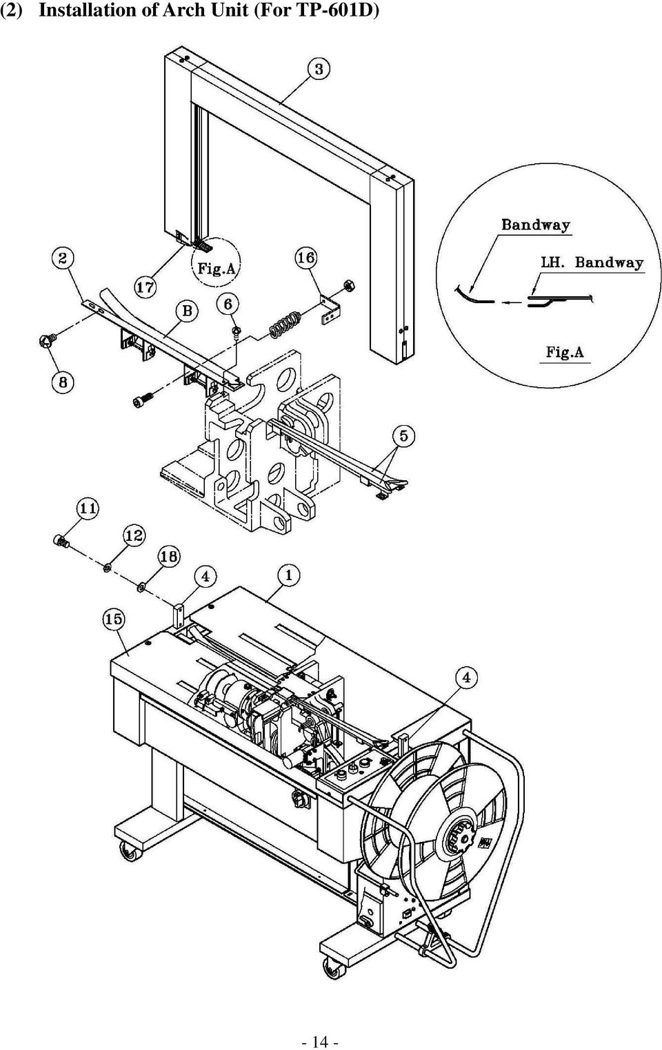
19 a. Take the upper table, 5 off. b. Take the LH bandway 2 off. 6 TMS, M5 8 PC 8 TMS, M6 8 2PC HBS, M8 5 4PC 2 SW, M8 4PC 8 PW, M8 (A) 4PC c. Slide the arch unit 3 into the fixing brackets 4 and fix both sides of the arch frame with 2 8. * Please note that is imperative to open the flaps of RH bandway 5 to protect them when installing the arch unit in. (open the flaps, before inserting the arch unit in) d. Set the LH bandway 2, with 6 and 8. d-. Please note that the arch bandway (refer Fig. A) should be positioned between LH bandway and its fixing bracket. d-2. Please set the LH bandway 2 closely to 7 guiding angle (PART NO. T ). d-3. Push the 6 Band guide Spring Bracket backward to check if B will be automatically turned open. If so, the installation is OK. e. Position the upper table 5 onto the machine body
 should be positioned between LH bandway and its fixing bracket. d-2.")
20 (3) How to Load P.P. Strap a. TP-60D Ensure that the power switch is turned off before loading P.P. strap. Step Place a strap coil on the reel drum in according to the arrow direction as indicated on the Reel Out Circular 9. After placing it, put the Reel Out Circular on the strap coil and tighten it by the Reel Nut Handle 0. Step 2 Thread the tip of P.P. strap into the Band Guide Roller. After that, push it through the Free Angle 2. At this moment, twist the strap so that the inside part of the P.P. strap turns out downward and outside surface touches on the roller. See the drawing. Step 3 Insert P.P. strap into the Pool Feed Shooter 3, pushing the lever 4 down and feed P.P. strap about -2 cm beyond Pool roller 5 Step 4 Turn on the power supply switch, and then push Reset Switch 7. After about 4 seconds, the strap will automatically go into the arch and pool

21 b. TP-60L Ensure that the power switch is turned off before loading P.P. strap. Step Place a strap coil on the reel drum in according to the arrow direction as indicated on the Reel Out Circular 9. After placing it, put the Reel Out Circular on the strap coil and tighten it by the Reel Nut Handle 0. Step 2 Thread the tip of P.P. strap into the Roller Bracket Ass'y 2. After that, thread it through the Band Guide Roller. Step 3 Insert P.P. strap into Pool Feed Shooter 3 and turn Accumulator Main Roller 4 until the P.P. strap about -2 cm beyond the Main Roller 4. Step 4 Turn on the power supply switch, and then push Reset Switch 7. After about 4 seconds, the strap will automatically go into the arch and pool
22 (4) How to Operate a. Turn on the Main power switch (make a 90-degree clockwise turn). The front door will be locked at the same time. [If you want to open the front door, turn off the main power switch first (make a 90-degree counterclockwise turn). In this way, the operator can open the front door without risk.] (See drawing below) b. Wait for about 3 minutes until the heater element reaches its required operating temperature. c. Place a package in the middle of the chute. d. Set tension with Tension Adjustment Knob (VR)(see page part I P 4 ) e. Push start switch (see page part I P ) or actuate foot pedal switch to start strapping. The strapping operation is repeated if the start switch is pushed again
23 6. Adjustments () Heater temperature mechanism Set the knob to position 3 or 4 Adjust the heater temperature by selecting a value between and 6. Choose the suitable temperature, bearing in mind the environmental conditions of the machine. If the heater temperature is too high or too low, a proper seal will not be obtained. Gradually increase or reduce the heater-knob value until obtaining an optimum seal
24 (2) Feed and take-up mechanism If this unit is not correctly adjusted, strap feed and take-up will become irregular. Normally, this unit is set to accept P.P. strap with the thicknesses of 0.55mm-0.75mm. If a different strap thickness is used, adjust the section marked by a circle in the drawing so that the clearance between the Upper Roller Spring 23 and the Upper Shaft Spring Hook 24 should be the thickness of the strap you are using. Strap can only be taken up properly if this unit is precisely adjusted. (If not, strap will be sealed before being tightened around the package) Moreover, strap will leave the chute arch track when feeding into it if there is no clearance. a. Check if the control unit returns to its original position. Insert the strap between Feed Roller 22 and Upper Feed Roller 2. b. Loosen 2 Bolts 27 holding the right-hand Block Arm 25 with the Press Arm Shaft 26. Press Arm Shaft can then easily be moved by hand. c. Adjust so that there is a clearance between the Upper Roller Spring 23 and the Upper Shaft Spring Hook 24 the same as the thickness of the strap you are using. d. Tighten 2 Bolts 27. The thickness of the strap you are using
25 (3) How to adjust LS3, LS2 Figure : LS-3 Home Position Figure - M6 screw Cam Follower Tension Cam Figure : LS-2 Figure 2- Take-up Cooling Time Feeding Figure shows the correct position for LS3 Proximity Sensor 3 and the Limit Switch Cam 32 while the machine is in home position. The machine will stop as soon as the LS3 Proximity Sensor 3 detects that Limit Switch Cam 32 is activated. At this time, the Cam Follower 4 must stop at the corner position on the Tension Cam 42 as shown in figure -. If not, please adjust according to the following instructions. Adjustment If Cam Follower 4 stops before the correct position: a. Loosen the two M6 screws and turn the Cam Roller slightly clockwise, then tighten the M6 screws. b. Reset the machine and allow it to cycle again to ensure that the Cam Follower 4 stops at the correct position. c. If the problem has not been eliminated, please repeat the "Step One" until the Cam Follower 4 stops at the correct position
26 If Cam Follower 4 stops beyond the correct position: Please also loosen the M6 screws but turn the Cam Roller slightly counterclockwise until the Cam Follower 4 stops at the correct position. Figure 2 shows the correct position for LS2 Proximity Sensor 33 against the lobes of the Limit Switch Cam 34 while machine is running. When LS2 Proximity Sensor 33 detects Lobe A of the activated running Limit Switch Cam 34, the machine will stop about 0.3 seconds so that the machine can switch to take-up. In the meantime, Cam Follower 4 has to stay on the corner position of the Tension Cam 42 as shown in figure 2-. If the Cam Follower is not at the correct position, please make the same adjustment as for LS
27 (4) Amount of strap in Accumulator Box a. TP-60D The machine has already been set in its Accumulator Box. However, some adjustment may be required, depending on the actual quality or thickness of the strap used. If adjustment is necessary, proceed as shown in the following drawing. a-. In case that there is an insufficient amount of strap in the Accumulator Box, loosen the Nut 27 and turn the Screw Bolt 28 counterclockwise. a-2. In case that there is an excessive amount of strap in the Accumulator Box, loosen the Nut 27 and turn the Screw Bolt 28 clockwise
28 b. TP-60L Fig A: If you have moved the LS4 Micro Switch to the left up to the bottom but you still do not have enough P.P. strap in the accumulator box, you can loosen nut E and turn the bolt D C.C.W. increase the amount of P.P. strap in the accumulator box. Finally tighten the nut E. T Micro Switch (LS4) M6 Screw T
29 7. Maintenance Warning: Before any maintenance or repairs on the machine, set the Main Power Switch to "O" (OFF). Wait about 5 minutes for cooling down the heater to avoid burns with this area. () Cleaning and Lubrication The high reliability and long service life of the strapping machine will depend on regular cleaning and maintenance. ATTENTION! All the important strap transport components, such as the feeding rollers and the strap guides, must be kept free from oil and grease. (lubricant) The lubricant has to be non-resinous. The lubricant is SAE 30 (2) Maintenance Only use original spare parts supplied by manufacturer. Daily: Use air gun to clean the circled positions (nearby the cutters, strap guide and accumulating feeding rollers) daily Remove plastic residue in the machine
30 Monthly :( or 50,000 strapping cycles) Clean both sides of heater plate and polish with fine sandpaper if necessary ATTENTION: Make sure the welding plate is cool first!! Check supporting and cam rollers of strapping head for easy movement. The slide table must be moved back to home position automatically by the spring tension. Be sure to clean any debris in the tension jaw. 6 Months:(or 300,000 strapping cycles) Check heater plate, replace and readjust it if necessary. Check strap cutter in strapping head, replace it if necessary. Check that connector at wiring loom to printed circuit board is firmly fixed. Make machine ready for operation. Strap one bundle manually several times, paying attention to mal-functions, repeat procedure. Check strap accumulating function. Do proper adjustments to accumulating feeding pressure or the reel brake belt year :( or 600,000 strapping) Replace deflection roller if it shows visible changes. In case of loud noise at bearings: locate them, replace the bearings. Get machine ready for operation again, strap one bundle manually several times, paying attention to malfunctions. NOTE: Any other service must be performed by an authorized service representative. 8. How to Safely move the Machine a. Before moving the machine, be sure to unplug the power cord and put it in safe place to avoid any damage. b. Moving the machine by holding the Reel Guard to pull or push the machine. Note: Don t move the machine by pulling or pushing the arch unit
31 9. Troubleshooting () Incorrect strap feed and take-up Probable Causes Remedy a. Incorrect strap threading direction on a. Reload strap correctly (see page 6) reel holder b. Incorrect loading of strap b. Check if strap is twisted in loading section (see page 6) c. Strap gets in between strap coil and c. Reload strap Reel Flange d. Insufficient or excessive strap d. Adjust amount of strap accumulated (see page 23) e. Dust and strap residues in Feed Unit e. Check and clean unit f. Strap end is split f. Adjust Cutter Tension Spring or change cutter g. Loose strap at Reel Unit g. Adjust or change Brake Tension Arm Spring h. Strap jumps out of arch track h. Adjust F/R mechanism (see page 20) i. Poor quality of strap i. Cut off the damaged part of strap or change the roll j. Improper positioning of package on j. Replace the package in the center of the Table Top Sealing Head (2) Strap unsealed Probable Causes Remedy a. Wire inside or outside of Heater is a. Check wire or change Heater broken, loose or out of connect b. Improper setting of temperature b. Adjust Heater Temperature (see page 9) c. Value set at Tension knob is too high c. Adjust Tension Knob (see page ) or increase weld cooling time (3) Improper strap tensioning Probable Causes Remedy Value set for Timer T is too short Adjust Timer T (see page 2)
32 0. Wiring Diagram
33 - 29 -
34 - 30 -
35 - 3 -
36 - 32 -
37 - 33 -
38 - 34 -
39 - 35 -
40 - 36 -
41 - 37 -
42 - 38 -
43 - 39 -
44 - 40 -
45 - 4 -
46 - 42 -
47 - 43 -
48
49 PART II CONTENTS. Strapping Head Unit 2. Bandway Unit 3 3. Accumulator Unit Reel Unit Body Frame Unit Electric Control Group Auto Strap Feeding Unit 09
50
51 STRAPPING HEAD UNIT T T REF. NO. PART NO. DESCRIPTION Q'TY REMARKS T T S T T S T T S T T S T T S T T S T T S T T S Strapping Head Unit (For TP-60D, 2mm) Strapping Head Unit (For TP-60D, 2mm)(Stainaless Steel Model) Strapping Head Unit (For TP-60D, 9mm) Strapping Head Unit (For TP-60D, 9mm)(Stainaless Steel Model) Strapping Head Unit (For TP-60D3, 2mm) Strapping Head Unit (For TP-60D3, 2mm)(Stainaless Steel Model) Strapping Head Unit (For TP-60D3, 9mm) Strapping Head Unit (For TP-60D3, 9mm)(Stainaless Steel Model) Strapping Head Unit (For TP-60L, 2mm) Strapping Head Unit (For TP-60L, 2mm)(Stainaless Steel Model) Strapping Head Unit (For TP-60L, 9mm) Strapping Head Unit (For TP-60L, 9mm)(Stainaless Steel Model) Strapping Head Unit (For TP-60L3, 2mm) Strapping Head Unit (For TP-60L3, 2mm)(Stainaless Steel Model) Strapping Head Unit (For TP-60L3, 9mm) Strapping Head Unit (For TP-60L3, 9mm)(Stainaless Steel Model) T Cam Group SEE PAGE 4-2 -
52 STRAPPING HEAD UNIT T T REF. NO. PART NO. DESCRIPTION Q'TY REMARKS 2 T Slide Table Group SEE PAGE 7 T S Slide Table Group (Stainaless Steel SEE PAGE 7 Model) 3 T Press Group SEE PAGE T S Press Group (Stainaless Steel Model) SEE PAGE 4 T Heater Group SEE PAGE 6 5 T Strapping Head Group (For TP-60D) SEE PAGE 9 T Strapping Head Group (For TP-60L) SEE PAGE 9 6 T Tension Group SEE PAGE 2 T S Tension Group (Stainaless Steel SEE PAGE 2 7 T Feed Group (For TP-60D/TP-60L, SEE PAGE 25 2mm) T S Feed Group (For TP-60D/TP-60L, SEE PAGE 25 2mm) T Feed Group (For TP-60D/TP-60L, SEE PAGE 25 9mm) T S Feed Group (For TP-60D/TP-60L, SEE PAGE 25 9mm) T Feed Group (For TP-60D3/TP-60L3, SEE PAGE 25 2mm) T S Feed Group (For TP-60D3/TP-60L3, SEE PAGE 25 2mm) T Feed Group (For TP-60D3/TP-60L3, SEE PAGE 25 9mm) T S Feed Group (For TP-60D3/TP-60L3, 9mm) SEE PAGE
53
54 - CAM GROUP T REF. NO. PART NO. DESCRIPTION Q'TY REMARKS T6--00 Tension Cam 2 T Cam Shaft End Plate 3 T6--03 Limit Switch Cam (LS2) 4 T Limit Switch Cam (LS3) 6 KYA Key, T6--07 Gear Box Pulley 8 T6--08 Limit Switch Bracket 9 BR6205ZZ Bearing, 6205ZZ 2 0 T V-Belt (A26) T Magnet Brake 4 T Gear Box 42 T Cam Ass'y SEE PAGE 6 5 HBS0845H HBS, M8 45 (H) 4 52 HBS0825 HBS, M HBS062 HBS, M HSS060G HSS, M6 0 (G) 6 55 PW08B PW, M8 (B) 4 56 SW08 SW, M SW06 SW, M6 2 6 SW04 SW, M PMS0408 PMS, M
55
56
57 -2 SLIDE TABLE GROUP T REF. NO. PART NO. DESCRIPTION Q'TY REMARKS T Slide Table Group T S Slide Table Group (Stainless Steel Model) T Slide Table Frame 2 T Slide Table Frame Shaft 4 T Slide Table Back Adjuster 5 T Slide Table Stopper 6 T Slide Table T S Slide Table 7 T Strap Guide 8 T Flap Connecting Spring Bracket 9 T S.F.S. Ass'y T S S.F.S. Ass'y 0 T Press Arm End Plate T Slide Table Spring Hook 2 T Slide Table Tension Spring 4 BR6304ZZ Bearing, 6304ZZ 2 5 T Cam Follower, KR22 LL 6 ER5 Snap Ring, E T Support 8 T Lever 9 T Bracket 20 T Spring 2 T Bushing 27 T Spring 4 T Strap Guide Arm Ass'y SEE PAGE 0 50 HBS0630 HBS, M HBS025H HBS, M0 25 (H) 52 HBS0830 HBS, M HBS0650H HBS, M6 50 (H) 2 54 HBS0620N HBS, M6 20 (N) 4 HBS0620S HBS, M HBS0625 HBS, M HSS080G HSS, M8 0 (G) 2 57 TMS060 TMS, M PW08A PW, M8 (A) 6 PW06A PW, M6 (A) 4-8 -
58 -2 SLIDE TABLE GROUP T REF. NO. PART NO. DESCRIPTION Q'TY REMARKS 63 SW06 SW, M HBS066 HBS, M HBS0408 HBS, M TMS042 TMS, M HN08 HN, M8 7 SW04 SW, M SW04S SW, M4 74 NTE04 NTE, M4 76 HN06 HN, M SW03 SW, M TA-07 Return Spring 8 T Sensor Plate 82 T Loop-eject Lever 83 T Loop-eject Plate T S Loop-eject Plate 84 HN03 HN, M HN04 HN, M HN04S HN, M4 87 PMS046 PMS, M PMS042 PMS, M FMS0508 FMS, M5 8 2 FMS0508S FMS, M T Detector Plate 97 T LH Bandway Stop Spring - 9 -
59
60
61 -3 PRESS GROUP T REF. NO. PART NO. DESCRIPTION Q'TY REMARKS T Press Group T S Press Group T Press Arm Shaft 2 T Cutter Tension Spring Hook 3 T Upper Roller Spring 4 T Upper Shaft Spring Adjuster 5 T Press Tension Spring 3 6 T Cutter Tension Spring 7 T Press Arm End Plate 8 BR6304ZZ Bearing, 6304ZZ 2 9 ER5 Snap Ring, E-5 4 T RH, Block Arm Ass'y SEE PAGE 3 T S RH, Block Arm Ass'y (Stainless Steel SEE PAGE 3 Model) 42 T Center Block Arm Ass'y SEE PAGE 4 T S Center Block Arm Ass'y (Stainless SEE PAGE 4 Steel Model) 43 T LH, Block Arm Ass'y SEE PAGE 5 5 HBS0620 HBS, M HSS065G HSS, M6 5 (G) 2 53 TMS060 TMS, M HN08 HN, M HN06 HN, M PW08A PW, M8 (A) 57 PW06B PW, M6 (B) 2 58 SW06 SW, M6-2 -
62
63
64
65
66 -4 HEATER GROUP T REF. NO. PART NO. DESCRIPTION Q'TY REMARKS T Heater Cover 2 T Heater Crank Spring 3 T Heater Slider Guide (L) 4 T Heater Slider Guide (R) 5 T Heater Crank Shaft 6 ER5 Snap Ring, E T Heater Stopper 8 LA Label 2 T Activated Carbon Filter (Option) 22 T Nipple (Option) 23 T Smoke-Exhaustion Pipe (Option) 24 T Fan (For Smoke)(Option) 4 T Heater Ass'y 42 T Heater Crank Ass'y SEE PAGE 8 43 T Smoke-exhaustion system, with activaed carbon filter. (Option) T Smoke-exhaustion system, without activated carbon filter. (Option) 5 HSS060G HSS, M6 0 (G) 2 52 HBS066 HBS, M TMS0408 TMS, M
67
68
69 -5 STRAPPING HEAD GROUP T T REF. NO. PART NO. DESCRIPTION Q'TY REMARKS T Strapping Head Group (For TP-60D) T Strapping Head Group (For TP-60L) T Strapping Head Frame 2 T6--50 Band Width Block 5 HBS0820 HBS, M8 20 (For TP-60D) 4 HBS0825 HBS, M8 25 (For TP-60L) 4 52 HBS0620 HBS, M PW06B PW, M6 (B) 55 SW08 SW, M PW08C PW, M8 (C) 4 6 T Bracket 63 HBS062 HBS, M SW06 SW, M
70
71 -6 TENSION GROUP REF. NO. PART NO. DESCRIPTION Q'TY REMARKS T Tension Group T S Tension Group T6--60 Tension Arm Shaft 2 T Tension Arm Spring 4 T Tension Arm Spacer 2 6 T Tension Arm Spring Hook L-Type 7 BRHK256 Bearing, HK ER5 Snap Ring, E-5 2 T BRIR20257 Bearing, IR SP0680 Spring Pin, T Tension Arm Ass'y SEE PAGE T Tension Jaw Ass'y T S Tension Jaw Ass'y (Stainless Steel Model) 53 HN08 HN, M PW08B PW, M8 (B)
72
73 -6- TENSION ARM ASS'Y T REF. NO. PART NO. DESCRIPTION Q'TY REMARKS 9 T Support Plate 20 T Collar 3 2 T Bracket Set 22 T6--60 Motor (M5-) Set 48 SW08 SW, M8 49 SW05 SW, M MB504 Metal Bushing, HSS080G HSS, M8 0 (G) 2 52 HN08 HN, M8 56 HN06 HN, M6 57 THS0540 THS, M
74
75 -7 FEED GROUP T T REF. NO. PART NO. DESCRIPTION Q'TY REMARKS T6--70 V-Belt M-22 (For TP-60D/TP- 60L) T V-Belt M-23 (For TP-60D3/TP- 60L3) 4 T Feed Ass'y (For 2mm) SEE PAGE 27 T S Feed Ass'y (For 2mm)(Stainless Steel SEE PAGE 27 Model) T Feed Ass'y (For 9mm) SEE PAGE 27 T S Feed Ass'y (For 9mm)(Stainless Steel SEE PAGE 27 Model) 42 T Upper Adjusting Weight Ass'y SEE PAGE 30 (For TP-60D) T Upper Adjusting Weight Ass'y (For TP-60L) SEE PAGE
76
77 -7- FEED ASS'Y T T REF. NO. PART NO. DESCRIPTION Q'TY REMARKS T Feed Ass'y (For 2mm) T S Feed Ass'y (For 2mm)(Stainless Steel Model) T Feed Ass'y (For 9mm) T S Feed Ass'y (For 9mm)(Stainless Steel Model) 2 T Upper Feed Roller (For 2mm) T Upper Feed Roller (For 9mm) 3 T Upper Feed Roller Shaft 4 T Feed Roller T6--740S Feed Roller 5 T Lever Holder 6 T Feed Roller Pulley 7 T Feed Shooter (For 2mm) T6--770S Feed Shooter (For 2mm)(Stainless Steel Model) T6--77 Feed Shooter (For 9mm) T6--77S Feed Shooter (For 9mm)(Stainless Steel Model) 8 T Feed Shooter Cover T6--780S Feed Shooter Cover (Stainless Steel Model) 9 T Upper Feed Roller Set (For 2mm) T Upper Feed Roller Set (For 9mm) 0 BR628ZZ Bearing, 628ZZ BR6202ZZ Bearing, 6202ZZ 4 2 RR24 Snap Ring, H RR35 Snap Ring, H ER2 Snap Ring, E-2 5 HBS0645H HBS, M6 45 (H) 2 HBS0645HS HBS, M6 45 (H)(Stainless Steel 2 Model) 52 HBS066 HBS, M
78 -7- FEED ASS'Y T T REF. NO. PART NO. DESCRIPTION Q'TY REMARKS 53 HSS065G HSS, M6 5 (G) 54 HSS060G HSS, M6 0 (G) 2 55 PMS060 PMS, M6 0 2 PMS060S PMS, M HN06 HN, M
79
80
81 2 BANDWAY UNIT T T REF. NO. PART NO. DESCRIPTION Q'TY REMARKS T Bandway Unit (For 2mm) T S Bandway Unit (For 2mm)(Stainless Steel Model) T Bandway Unit (For 9mm) T S Bandway Unit (For 9mm)(Stainless Steel Model) T Bandway Group (For 850W, 2mm) SEE PAGE 32 T6-2-0 Bandway Group (For 850W, 9mm) SEE PAGE 32 T Bandway Group (For 650W, 2mm) SEE PAGE 32 T Bandway Group (For 650W, 9mm) SEE PAGE 32 T Bandway Group (For 050W, 2mm) SEE PAGE 32 T Bandway Group (For 050W, 9mm) SEE PAGE 32 T Bandway Group (For 250W, 2mm) SEE PAGE 32 T Bandway Group (For 250W, 9mm) SEE PAGE 32 T Bandway Group (For 450W, 2mm) SEE PAGE 32 T Bandway Group (For 450W, 9mm) SEE PAGE 32 T Bandway Group (For 650W, 2mm) SEE PAGE 32 T Bandway Group (For 650W, 9mm) SEE PAGE 32 T Bandway Group (For 850W, 2mm) SEE PAGE 32 T Bandway Group (For 850W, 9mm) SEE PAGE 32 2 T Chute Arch Group SEE PAGE 38 T S Chute Arch Group (Stainless Steel Model) SEE PAGE
82
83 2- BANDWAY GROUP T T6-2-0 REF. NO. PART NO. DESCRIPTION Q'TY REMARKS T Bandway Group (For 850W, 2mm) T6-2-0 Bandway Group (For 850W, 9mm) T Bandway Group (For 650W, 2mm) T Bandway Group (For 650W, 9mm) T Bandway Group (For 050W, 2mm) T Bandway Group (For 050W, 9mm) T Bandway Group (For 250W, 2mm) T Bandway Group (For 250W, 9mm) T Bandway Group (For 450W, 2mm) T Bandway Group (For 450W, 9mm) T Bandway Group (For 650W, 2mm) T Bandway Group (For 650W, 9mm) T Bandway Group (For 850W, 2mm) T Bandway Group (For 850W, 9mm) 4 T RH Bandway Ass'y (For 2mm) SEE PAGE 34 T RH Bandway Ass'y (For 9mm) SEE PAGE 34 T RH Bandway Ass'y (Only 650W, 2mm) SEE PAGE 34 T6-2-0 RH Bandway Ass'y (Only 650W, 9mm) SEE PAGE T LH Bandway Ass'y (For 850W, 2mm) SEE PAGE 35 T LH Bandway Ass'y (For 850W, 9mm) SEE PAGE 35 T LH Bandway Ass'y (For 650W, 2mm) SEE PAGE 35 T LH Bandway Ass'y (For 650W, 9mm) SEE PAGE 35 T LH Bandway Ass'y (For 050W, 2mm) SEE PAGE 35 T LH Bandway Ass'y (For 050W, 9mm) SEE PAGE 35 T LH Bandway Ass'y (For 250W, 2mm) SEE PAGE 35 T LH Bandway Ass'y (For 250W, 9mm) SEE PAGE 35 T LH Bandway Ass'y (For 450W, 2mm) SEE PAGE 35 T LH Bandway Ass'y (For 450W, 9mm) SEE PAGE 35 T LH Bandway Ass'y (For 650W, 2mm) SEE PAGE 35 T LH Bandway Ass'y (For 650W, 9mm) SEE PAGE 35 T LH Bandway Ass'y (For 850W, 2mm) SEE PAGE 35 T LH Bandway Ass'y (For 850W, 9mm) SEE PAGE 35 5 TMS0608 TMS, M
84 2- BANDWAY GROUP T T6-2-0 REF. NO. PART NO. DESCRIPTION Q'TY REMARKS 53 HBS0650 HBS, M TMS0508 TMS, M HN06 HN, M PW06A PW, M6 (A)
85
86
87 2--2 LH BANDWAY ASS'Y T T REF. NO. PART NO. DESCRIPTION Q'TY REMARKS T LH Bandway Ass'y (For 850W, 2mm) T LH Bandway Ass'y (For 850W, 9mm) T LH Bandway Ass'y (For 650W, 2mm) T LH Bandway Ass'y (For 650W, 9mm) T LH Bandway Ass'y (For 050W, 2mm) T LH Bandway Ass'y (For 050W, 9mm) T LH Bandway Ass'y (For 250W, 2mm) T LH Bandway Ass'y (For 250W, 9mm) T LH Bandway Ass'y (For 450W, 2mm) T LH Bandway Ass'y (For 450W, 9mm) T LH Bandway Ass'y (For 650W, 2mm) T LH Bandway Ass'y (For 650W, 9mm) T LH Bandway Ass'y (For 850W, 2mm) T LH Bandway Ass'y (For 850W, 9mm) 3 T LH Bandway Flap Pin 2 (For 650W~050W) LH Bandway Flap Pin 3 (For 250W~450W) LH Bandway Flap Pin 4 (For 650W~850W) 4 T LH Bandway Flap Spring (For 650W~050W) LH Bandway Flap Spring 2 (For 250W~450W) LH Bandway Flap Spring 3 (For 650W~850W) 5 T LH Bandway Flap Spring 6 T Pillar (For 450W~850W) TMS0508 TMS, M5 8 (For 450W~850W)
88 - 37 -
89
90
91 2-2- ARCH ASS'Y T REF. NO. PART NO. DESCRIPTION Q'TY REMARKS T Arch Ass'y T S Arch Ass'y T Arch Frame (For 850W 600H) T S Arch Frame (For 850W 600H) 2 T Arch Bandway (For 850W 600H) 3 T Arch Cover, Front (For 850W 600H) T S Arch Cover, Front (For 850W 600H) 4 T Arch Cover, Rear (For 850W 600H) T S Arch Cover, Rear (For 850W 600H) 5 T Upper Guide Rail (For 850W) T S Upper Guide Rail (For 850W) T Upper Guide Rail (For 050W) T S Upper Guide Rail (For 050W) T Upper Guide Rail (For 250W) T S Upper Guide Rail (For 250W) T Upper Guide Rail (For 450W) T S Upper Guide Rail (For 450W) T Upper Guide Rail (For 650W) T S Upper Guide Rail (For 650W) T Upper Guide Rail (For 850W) T S Upper Guide Rail (For 850W) T Upper Guide Rail (For 650W) T S Upper Guide Rail (For 650W)
92 2-2- ARCH ASS'Y T REF. NO. PART NO. DESCRIPTION Q'TY REMARKS 6 T RH Side Guide Rail (For 600H) T S RH Side Guide Rail (For 600H) T RH Side Guide Rail (For 800H) T S RH Side Guide Rail (For 800H) T RH Side Guide Rail (For 000H) T S RH Side Guide Rail (For 000H) T RH Side Guide Rail (For 200H) T S RH Side Guide Rail (For 200H) T RH Side Guide Rail (For 400H) T S RH Side Guide Rail (For 400H) 7 T LH Side Guide Rail (For 600H) T S LH Side Guide Rail (For 600H) T LH Side Guide Rail (For 800H) T S LH Side Guide Rail (For 800H) T LH Side Guide Rail (For 000H) T S LH Side Guide Rail (For 000H) T LH Side Guide Rail (For 200H) T S LH Side Guide Rail (For 200H) T LH Side Guide Rail (For 400H) T S LH Side Guide Rail (For 400H) 8 T Corner Guide Rail, Upper 4 T S Corner Guide Rail, Upper (Stainless 4 Steel Model) 9 T Corner Guide Rail, Lower (LH) T S Corner Guide Rail, Lower (LH) - 4 -
93 2-2- ARCH ASS'Y T REF. NO. PART NO. DESCRIPTION Q'TY REMARKS 0 T Corner Guide Rail, Lower (RH) T S Corner Guide Rail, Lower (RH) T Guide Rail Hinge ()(For 850W 600H) 2 T K-Type Guide Rail Hinge Shaft 2 (For 850W 600H) 3 T Guide Rail Hinge (2) 4 T Guide Rail Hinge Shaft (For 850W 600H) 5 T Arch Guide Rail Spring (For 850W 600H) 6 T Guiding Angle, LH Front T S Guiding Angle, LH Front (Stainless Steel Model) 8 T Guiding Angle, RH Front T S Guiding Angle, RH Front (Stainless Steel Model) 9 T Guiding Angle, RH Rear T S Guiding Angle, RH Rear (Stainless Steel Model) 24 T Back Guide Plate, Upper (For 850W) T S Back Guide Plate, Upper (For 850W) T Back Guide Plate, Upper (For 050W) T S Back Guide Plate, Upper (For 050W) T Back Guide Plate, Upper (For 250W) T S Back Guide Plate, Upper (For 250W) T Back Guide Plate, Upper (For 450W) T S Back Guide Plate, Upper (For 450W) T Back Guide Plate, Upper (For 650W) T S Back Guide Plate, Upper (For 650W)
94 2-2- ARCH ASS'Y T REF. NO. PART NO. DESCRIPTION Q'TY REMARKS T Back Guide Plate, Upper (For 850W) T S Back Guide Plate, Upper (For 850W) T Back Guide Plate, Upper (For 650W) T S Back Guide Plate, Upper (For 650W) 25 T Back Guide Plate, Side (For 600H) 2 T S Back Guide Plate, Side (For 600H) 2 T Back Guide Plate, Side (For 800H) 2 T S Back Guide Plate, Side (For 800H) 2 T Back Guide Plate, Side (For 000H) 2 T S Back Guide Plate, Side (For 000H) 2 T Back Guide Plate, Side (For 200H) 2 T S Back Guide Plate, Side (For 200H) 2 T Back Guide Plate, Side (For 400H) 2 T S Back Guide Plate, Side (For 400H) 2 26 T Back Guide Plate, Corner Upper 2 T S Back Guide Plate, Corner Upper 2 27 T Back Guide Plate, LH Lower T S Back Guide Plate, LH Lower 28 T Back Guide Plate, RH Lower T S Back Guide Plate, RH Lower 29 PN04 PN, 4 2 PN04S PN,
95 2-2- ARCH ASS'Y T REF. NO. PART NO. DESCRIPTION Q'TY REMARKS 52 TMS0508S TMS, M5 8 (SUS) 8 53 TMS0408 TMS, M HBS0440H HBS, M4 40 (H) 55 HN04 HN, M4 56 SW04 SW, M4 6 LA Label 2 62 LA-4070 Label
96
97 3 ACCUMULATOR UNIT T T REF. NO. PART NO. DESCRIPTION Q'TY REMARKS T Accumulator Group (For TP-60D, SEE PAGE 47 2mm) T S Accumulator Group (For TP-60D, SEE PAGE 47 2mm) T Accumulator Group (For TP-60D, SEE PAGE 47 9mm) T S Accumulator Group (For TP-60D, SEE PAGE 47 9mm) 2 T Accumulator Box Group (TP-60D, SEE PAGE 52 2mm) T S Accumulator Box Group (TP-60D, SEE PAGE 52 2mm) T Accumulator Box Group (TP-60D, SEE PAGE 52 9mm) T S Accumulator Box Group (TP-60D, SEE PAGE 52 9mm) 3 T Accumulator Box Group (TP-60L, SEE PAGE 54 2mm) T S Accumulator Box Group (TP-60L, SEE PAGE 54 2mm) T Accumulator Box Group (TP-60L, SEE PAGE 54 9mm) T S Accumulator Box Group (TP-60L, 9mm) SEE PAGE
98
99 3- ACCUMULATOR GROUP T (For TP-60D) T REF. NO. PART NO. DESCRIPTION Q'TY REMARKS T Accumulator Group (For 2mm) T S Accumulator Group (For 2mm) T Accumulator Group (For 9mm) T S Accumulator Group (For 9mm) T Balance Bar (For 2mm) T6-3-0 Balance Bar (For 9mm) 2 T Accumulator Balance Spring 3 T Accumulator Adjusting Bolt T S Accumulator Adjusting Bolt (Stainless Steel Model) 5 T Accumulator Spring Adjusting 6 T Spring 7 LA Label (Direction) 8 T V-Belt, M-27 9 T Balance Bar Spacer (Only 2mm) 0 T Twist Stopper 4 T Accumulator Ass'y (For 2mm) SEE PAGE 50 T Accumulator Ass'y (For 9mm) SEE PAGE 50 5 HBS0620 HBS, M HBS0620S HBS, M HBS066 HBS, M6 6 (For 2mm) 2 HBS062 HBS, M6 2 (For 9mm) 2 54 PMS035 PMS, M HN08 HN, M8 3 HN08S HN, M HN03 HN, M3 58 PW06C PW, M6 (C) 4 PW06CS PW, M6 (C)
100 3- ACCUMULATOR GROUP T (For TP-60D) T REF. NO. PART NO. DESCRIPTION Q'TY REMARKS 59 SW03 SW, M3 60 SW08 SW, M8 6 SW06 SW, M6 6 SW06S SW, M T Cover 63 PW05 PW, M SW05 SW, M HBS050 HBS, M PW06A PW, M6 (A)
101
102 3-- ACCUMULATOR ASS'Y T (For TP-60D) T REF. NO. PART NO. DESCRIPTION Q'TY REMARKS T Accumulator Ass'y (For 2mm) T Accumulator Ass'y (For 9mm) T6-3-0 Accumulator Bearing Case 2 T Accumulator Lower Shaft 3 T Accumulator Lower Roller 4 T Accumulator Main Roller & Shaft 5 T Accumulator Balance Bar Holder 6 T Accumulator Feed Shooter (For 2mm) T6-3-6 Accumulator Feed Shooter (For 9mm) 7 T Accumulator Lower Shaft Spring Hook 8 T Knob 9 T Bearing Collar 2 0 T Feed Roller Pulley BR6202ZZ Bearing, 6202ZZ 4 2 BR620ZZ Bearing, 620ZZ 2 3 BR6902ZZ Bearing, 6902ZZ 2 5 RR32 Snap Ring, H ER2 Snap Ring, E SR2 Stop Ring, S-2 5 HBS0635H HBS, M6 35 (H) 52 HSS065G HSS, M6 5 (G) 53 HSS060G HSS, M6 0 (G) 2 54 HSS0506G HSS, M5 6 (G) 55 HN06 HN, M6-5 -
103
104 3-2 ACCUMULATOR BOX GROUP T (For TP-60D) T REF. NO. PART NO. DESCRIPTION Q'TY REMARKS T Accumulator Box Group (For 2mm) T S Accumulator Box Group (For 2mm) T Accumulator Box Group (For 9mm) T S Accumulator Box Group (For 9mm) 3 T Accumulator Box Front, LH T S Accumulator Box Front, LH 5 T Spacer (For 9 mm) 2 T Spacer (For 2 mm) 2 5 HBS0508 HBS, M5 8 2 HBS0508S HBS, M PW05 PW, M5 2 PW05S PW, M HBS0425H HBS, M4 25 (H) 2 HBS0425HS HBS, M4 25 (H) 2 58 SW04 SW, M4 2 SW04S SW, M PW04 PW, M4 2 PW04S PW, M SW05 SW, M5 2 SW05S SW, M
105
106 3-3 ACCUMULATOR BOX GROUP T (For TP-60L) T REF. NO. PART NO. DESCRIPTION Q'TY REMARKS T Accumulator Box Group (For TP-60L, 2mm) T S Accumulator Box Group (For TP-60L, 2mm) T Accumulator Box Group (For TP-60L, 9mm) T S Accumulator Box Group (For TP-60L, 9mm) T Inlet Guide (For 9mm) T Inlet Guide (For 2mm) 3 T Strap Guide (For 9mm) T Strap Guide (For 2mm) 5 T Enclosed Plate (For 9mm) T Enclosed Plate (For 2mm) 6 T Enclosed Plate (For 9mm) T Enclosed Plate (For 2mm) 8 T Inlet Strap Guide, Upper (For 9mm) T S Inlet Strap Guide, Upper (For 9mm) T Inlet Strap Guide, Upper (For 2mm) T S Inlet Strap Guide, Upper (For 2mm) 9 T Inlet Strap Guide, Lower (For 9mm) T S Inlet Strap Guide, Lower (For 9mm) T Inlet Strap Guide, Lower (For 2mm) T S Inlet Strap Guide, Lower (For 2mm) 0 T Strap Guide Cover T S Strap Guide Cover (Stainless Steel Model) 2 T Strap Guide Bar (For 9mm) T Strap Guide Bar (For 2mm)
107 3-3 ACCUMULATOR BOX GROUP T (For TP-60L) T REF. NO. PART NO. DESCRIPTION Q'TY REMARKS 3 T Movable Strap Guide (For 9mm) T S Movable Strap Guide (For 9mm) T Movable Strap Guide (For 2mm) T S Movable Strap Guide (For 2mm) 4 T Lower Guide (For 9mm) T S Lower Guide (For 9mm)(Stainless Steel Model) T Lower Guide (For 2mm) T S Lower Guide (For 2mm)(Stainless Steel Model) 5 T Assistant Roller Ass'y (For 9mm) T Assistant Roller Ass'y (For 2mm) 6 T Balance Bar (For 9mm) T Balance Bar (For 2mm) 7 T Control Lever (For 9mm) T Control Lever (For 2mm) 8 T Pusher 20 T Motor Cover 2 2 T6--62 Motor (M5-) 2 22 T Spring 23 T Twist Stopper 2 24 T Spring 25 T Collar 26 T Grommet 27 T Strap Guide (For 9mm) T Strap Guide (For 2mm) 28 T Shaft T S Shaft 29 T Bracket 30 T Tube 3 T Support 32 T Sensor Lever 33 T Bracket
108 3-3 ACCUMULATOR BOX GROUP T (For TP-60L) T REF. NO. PART NO. DESCRIPTION Q'TY REMARKS 34 T Motor Support 35 T Shaft 36 T Assistant Roller (For 9mm) T Assistant Roller (For 2mm) 37 T Accumulator Main Roller T S Accumulator Main Roller (Stainless Steel Model) 38 T Collar 39 T Spacer 40 T Motor Ass'y (M3) 4 LA Label 2 42 T Earth Plate (3P) 43 TB-223 Washer 44 T Accumulator Adjusting Pin 2 45 TF-006 Micro Switch (LS4) 46 TF-007 Micro Switch (LS5) 47 MV--720 Bolt 48 T Twist 50 BR605ZZ Bearing, 605ZZ (For 9mm) 4 Bearing, 605ZZ (For 2mm) 6 5 BR608ZZ Bearing, 608ZZ 2 52 BR6900ZZ Bearing, 6900ZZ 2 53 KYA Key, MB00 Metal Bushing, HBS046N HBS, M4 6 (N) 3 56 HBS0425N HBS, M4 25 (N) 2 57 HBS0508N HBS, M5 8 (N) 8 58 HBS052N HBS, M5 2 (N) 6 59 HBS0608N HBS, M6 8 (N) 3 60 HBS062N HBS, M6 2 (N) 6 HBS066N HBS, M6 6 (N) 62 HBS066N HBS, M6 6 (N)(For 9mm) 3 HBS0620N HBS, M6 20 (N)(For 2mm) 3 63 HBS056N HBS, M5 6 (N) 64 HBS0530N HBS, M5 30 (N)
109 3-3 ACCUMULATOR BOX GROUP T (For TP-60L) T REF. NO. PART NO. DESCRIPTION Q'TY REMARKS 65 HBS0630N HBS, M6 30 (N) 2 68 FMS030 FMS, M FMS040 FMS, M FMS050 FMS, M PMS036 PMS, M TMS0408 TMS, M HN03 HN, M3 76 HN05 HN, M HN08 HN, M HN04 HN, M HSS0405GN HSS, M4 5 (G)(N) 5 HSS0405S HSS, M HSS0508GN HSS, M5 8 (G)(N) 4 8 HSS060GN HSS, M6 0 (G)(N) 2 82 HBS042N HBS, M4 2 (N) 3 84 PW04 PW, M PW05 PW, M PW06A PW, M6 (A) 8 87 SW03 SW, M SW04 SW, M SW05 SW, M SW06 SW, M6 8 9 SW08 SW, M8 92 PW08A PW, M8 (A)
110
111
112
113
114 4-2 REEL CONTROL GROUP T (For TP-60D) T REF. NO. PART NO. DESCRIPTION Q'TY REMARKS T Reel Control Group (For 200mm)(For TP-60D) T S Reel Control Group (For 200mm)(For TP-60D) T Reel Control Group (For 280mm) (For TP-60D)(Option) T S Reel Control Group (For 280mm)(For TP-60D) (Option) T Reel Unit Base 3 T Brake Tension Holder 4 T Brake Belt Tightener T S Brake Belt Tightener (Stainless Steel Model) 5 T Reel Shaft T S Reel Shaft 6 T Holder Shaft 2 T S Holder Shaft 2 7 T Reel Brake Arm T S Reel Brake Arm 8 T Brake Tension Arm Spring T S Brake Tension Arm Spring (Stainless Steel Model) 9 T Brake Tension Spring Ring 0 BR6205ZZ Bearing, 6205ZZ 2 MB525 Metal Bushing, T Collar 3 ER9 Snap Ring, E-9 ER9S Snap Ring, E-9 4 ER2 Snap Ring, E-2 5 ER2S Snap Ring, E SR08 Stop Ring, S-8 SR08S Stop Ring, S-8 6 T Spring Hook 7 T Set Block T S Set Block
TABLE-TYER / TABLE-TYER SS POWER STRAPPING MACHINES 04/12/07
 TABLE-TYER / TABLE-TYER SS POWER STRAPPING MACHINES 04/12/07 CONGRATULATIONS Thank you for purchasing your Table-Tyer Strapping Machine. The Table-Tyer has been designed to be a reliable, maintenance free
Number Wheeler P/N Description Set Rex P/N Notes 1 603500 Base 1 J001 2 603501 Support, Right 1 J002 3 603502 Support, Left 1 J003 4 600328 Nut (M8)
") 1 603500 Base 1 J001 2 603501 Support, Right 1 J002 3 603502 Support, Left 1 J003 4 600328 Nut (M8) 4 5 600130 Spring Washer (8mm) 4 6 600344 Roll Pin (M6x30) 4 7 600129 Socket Hd Cap Screw (M8x25) 4 8
1 603500 Base 1 J001 2 603501 Support, Right 1 J002 3 603502 Support, Left 1 J003 4 600328 Nut (M8) 4 5 600130 Spring Washer (8mm) 4 6 600344 Roll Pin (M6x30) 4 7 600129 Socket Hd Cap Screw (M8x25) 4 8
SECTION G2: CABLE PROCESSOR MODULE MAINTENANCE
 SECTION G2: CABLE PROCESSOR MODULE MAINTENANCE Cable Processor Module overview WARNING! When tipping the Cable Processor Module back, (after removing the toggle arm pin), use extreme caution not to drop
MBSAW. Meat Cutting Band Saw With Meat Grinder Assembly & Operating Instructions
 06/2011 MBSAW Meat Cutting Band Saw With Meat Grinder Assembly & Operating Instructions READ ALL INSTRUCTIONS AND WARNINGS BEFORE USING THIS PRODUCT. This manual provides important information on proper
Service manual. Website: www.andico.com.au CAUTION - BEFORE SERVICING THE UNIT, READ THE SAFETY - PRECAUTIONS IN THIS MANUAL.
 Website: www.andico.com.au Service manual CAUTION - BEFORE SERVICING THE UNIT, READ THE SAFETY - PRECAUTIONS IN THIS MANUAL. - ONLY FOR AUTHORISED SERVICE PERSONNEL. MODELS: MPK1-09CR-QB8 MPK1-12ER-QB6
INSTALLATION and OPERATION RANGE BALL CONVEYOR MODEL NO: BC-001AN
 Easy Picker Golf Products, Inc. 415 Leonard Blvd. N., Lehigh Acres, FL 33971 PH: 239-368-6600 FAX: 239-369-1579 Service: 800-982-4653 SALES: 800-641-4653 www.easypicker.com salesdept@easypicker.com INSTALLATION
DIAMOND Retractable Rodding Robot Model SPRAYROD-R
 2004-12-21 2 1 (23) DIAMOND Retractable Rodding Robot Model SPRAYROD-R 2004-12-21 2 2 (23) Table of contents 1 TECHNICAL DESCRIPTION...4 1.1 MAIN DETAILS...5 1.2 COMPONENTS DESCRIPTION...5 1.2.1 Pneumatic
GUTTER MACHINE CONTROLS STANDARD
 GUTTER MACHINE CONTROLS STANDARD Note: determine what type of control package is installed on the machine. --more-- All operators should familiarize themselves with the appropriate controls prior to any
15GAL STEEL OIL DRAIN WITH 110V PUMP
 15GAL STEEL OIL DRAIN WITH 110V PUMP OWNER S MANUAL WARNING: Read carefully and understand all ASSEMBLY AND OPERATION INSTRUCTIONS before operating. Failure to follow the safety rules and other basic safety
Multi-Pitch Pitching Machine USER MANUAL
 Multi-Pitch Pitching Machine USER MANUAL TABLE OF CONTENTS Thank you for purchasing the Cimarron Multi-Pitch Pitching Machine. The Cimarron Multi-Pitch Pitching Machine is a high performance pitching machine
Number Wheeler P/N Description Set Rex P/N Notes
 1 607051 Base 1 A050 2 607052 Motor Cover 1 A052 3 600778 Socket Hd Cap Screw (M8x60) 2 4 607053 Scrap Receiver 1 A053 5 607054 Tank Upper Cover 1 A054 6 607055 Oil Pot 1 A055 7 607056 Strainer 1 A056
Number Wheeler P/N Description Set Rex P/N Notes
 1 604041 Base 1 4041 2 604042 Base Cover 1 4042 3 608849 Washer (M5) 2 4 600124 Spring Washer (M5) 2 5 600329 Rd Hd Machine Screw (M5x8) 2 6 604047 Strainer 1 4047 7 600204 Rd Hd Machine Screw (M6x10)
SERVICE GUIDE For WARN PULLZALL 120v AC &100v AC P/N 685000 & 685001
 SERVICE GUIDE For WARN PULLZALL 120v AC &100v AC P/N 685000 & 685001 REPAIR / REPLACEMENT INSTRUCTIONS TROUBLE SHOOTING GUIDE 986765A2.doc Page 1 of 50 WARNING This guide identifies potential hazards and
POSEIDON 2-29, 2-25 & 2-22 POSEIDON 2-29, 2-25 & 2-22 XT
 POSEION 2-29, 2-25 & 2-22 POSEION 2-29, 2-25 & 2-22 XT Repair Manual Index A. Safety precautions 3 B. Technical data 4 C. Structure 5-6. Service / Repair 7-23 E. Tools 24 F. Function 25-26 G. Electric
PRODUCT MANUAL - M090
 PRODUCT MANUAL - M090 MODEL 203/266 ELECTRIC CAN OPENER 1 SAFETY CAUTION: SEVERED CAN LIDS HAVE CUTTING EDGES. USE OF A PROTECTIVE GLOVE OR TONGS IS ADVISED WHEN HANDLING LIDS. WARNING To avoid risk of
3000, 4000, 4100, 7500, 7700
 3000, 4000, 4100, 7500, 7700 Drum & Disc Brake Lathes s Identification READ these instructions before placing unit in service. KEEP these and other materials delivered with the unit in a binder near the
JANUS INTERNATIONAL CORPORATION INSTALLATION INSTRUCTIONS Pantheon Mini Operator
 JANUS INTERNATIONAL CORPORATION INSTALLATION INSTRUCTIONS Pantheon Mini Operator The Janus Pantheon mini operator does not typically require the provision of any additional site requirements other than
INFRARED QUARTZ WALL HEATER
 INFRARED QUARTZ WALL HEATER MODEL NO: IQ2000 PART NO: 6939004 MOUNTING & OPERATION INSTRUCTIONS GC0715 INTRODUCTION Thank you for purchasing this CLARKE Infrared Wall Heater. Before attempting to use this
1000-LB. TRAILER JACK OWNER S MANUAL
 1000-LB. TRAILER JACK OWNER S MANUAL WARNING: Read carefully and understand all INSTRUCTIONS before operating. Failure to follow the safety rules and other basic safety precautions may result in serious
Pet hair clipper. Model 96822. Diagrams within this manual may not be drawn proportionally.
 Pet hair clipper Model 96822 Cleaning And Operation Instructions Diagrams within this manual may not be drawn proportionally. Due to continuing improvements, actual product may differ slightly from the
758 Heavy-duty Ratchet Guy Wire Cutter
 INSTRUCTION MANUAL 758 Heavy-duty Ratchet Guy Wire Cutter Read and understand all of the instructions and safety information in this manual before operating or servicing this tool. Register this product
FJ2. 2 Ton Trolley Floor Jack Assembly & Operating Instructions
 FJ2 2 Ton Trolley Floor Jack Assembly & Operating Instructions READ ALL INSTRUCTIONS AND WARNINGS BEFORE USING THIS PRODUCT. This manual provides important information on proper operation & maintenance.
Operating Manual Please Read Before Operating Unit
 Operating Manual Please Read Before Operating Unit Model RT2S Wire Stripper & Component Lead Cleaner Service and All Spare Parts Available The Eraser Company, Inc. PO Box 4961/ Oliva Drive Syracuse, NY
Model 854/856. Operating and Assembly Manual. Palmor Products Inc. 5225 Serum Plant Road Thorntown, IN 46071
 Model 854/856 Operating and Assembly Manual Palmor Products Inc. 55 Serum Plant Road Thorntown, IN 46071 3/31/2015 SAFETY RULES Remember, any power equipment can cause injury if operated improperly or
DANGER DANGER. General Information. Safety Is Your Responsibility. Ordering Parts. Contact Information
 Safety Safety Is Your Responsibility DANGER To avoid personal injury or death, carefully read and understand all instructions pertaining to the Anthony Liftgates product. Do not attempt to install, operate,
USER INSTRUCTIONS FOR 10 LITRE PORTABLE DEHUMIDIFIER MODEL NO. DHMD102
 USER INSTRUCTIONS FOR 10 LITRE PORTABLE DEHUMIDIFIER MODEL NO. DHMD102 THANK YOU FOR CHOOSING YOUR NEW DEHUMIDIFIER. BEFORE USING THE UNIT READ THESE INSTRUCTIONS FULLY AND RETAIN THEM FOR FUTURE REFERENCE
Portable Air Conditioner
 Portable Air Conditioner Owner's Manual Model:3 in 1 12,000 Btu/h Series 3 Please read this owner s manual carefully before operation and retain it for future reference. CONTENTS 1. SUMMARY...1 2. PORTABLE
HYDRAULIC LIFT TABLE CART 2200-LB.
 HYDRAULIC LIFT TABLE CART 2200-LB. OWNER S MANUAL WARNING: Read carefully and understand all MACHINE ADJUSTMENT AND OPERATION INSTRUCTIONS before operating. Failure to follow the safety rules and other
- 2 - IMPORTANT SAFETY REMINDERS
 USER MANUAL IMPORTANT SAFETY REMINDERS This appliance should only be used for domestic cleaning, as described in this user guide. Please ensure that this guide is fully understood before operating the
Original Assembly Guide
 TCT Multipurpose Single Bevel Sliding Compound Mitre Saw Original Assembly Guide Read instructions before assembling this tool. Table of Contents GB Assembly Guide Read instructions before assembling this
Cable Drum Machine. Operation Manual BC260 SERIES. Cleans 1 1/4" to 3" lines up to 50'
 Cable Drum Machine Operation Manual BC260 SERIES Cleans 1 1/4" to 3" lines up to 50' Used For: Sink, Shower & Floor Drains 42FM " WARNING - Read All Instructions, When Using Electric Tools, Basic Safety
SERVICE PARTS LIST PAGE 1 OF 6 BASE ASSEMBLY SPECIFY CATALOG NO. AND SERIAL NO. WHEN ORDERING PARTS 12" DUAL BEVEL COMPOUND MITER SAW B27A
 PAGE 1 OF 6 BASE ASSEMBLY 00 0 EXAMPLE: Component Parts (Small #) Are Included When Ordering The Assembly (Large #). SPECIFY CATALOG NO. AND NO. WHEN ORDERING PARTS 1 02-80-0050 Thrust Bearing (1) 2 05-80-0510
GENUINE PARTS INSTALLATION INSTRUCTIONS
 GENUINE PARTS INSTALLATION INSTRUCTIONS DESCRIPTION: Illuminated Kick Plate APPLICATION: Rogue (2011) PART NUMBER: 999G6 GX010 KIT CONTENTS: Item A B C G H QTY 1 1 1 D 1 E 1 F 3 15 6 Description Kick Plate,
INSTRUCTION. Industrial Sewing Machines. No. 010012. First published : June 1997 Second edition : March 2001
 INSTRUCTION Industrial Sewing Machines First published : June 1997 Second edition : March 2001 No. 010012 INTRODUCTION Thank you for your purchasing Kansai Special's DLR Series. Read and study this instruction
Directions for use : Dosing chutes type DSX.
 Pag. 1-10 Directions for use : Dosing chutes type DSX. Introduction The linear vibrations of STILETTO consist of a drive part and a movable part which are connected to leave springs. The purpose of the
SELF-STEERING AXLE TABLE OF CONTENTS
 SELF-STEERING AXLE TABLE OF CONTENTS Section 1 - Introduction Section 2 - Pre-Installation Check List Section 3 - Ride Height Adjustments Section 4 - Suspension Mount Section 5 - Axle Mount Section 6 -
Operating Instructions
 Operating Instructions Series L 4000 Spring Driven Cord Reels 63 3 3 3 7A 63 0 63 3 3-RP 3 7B 63 X 6 3 3A 63 8 3 X 6 3 3A-RP 63 8 L 4000 63 3 3 3B 63 9 L 400 63 3-RP A 63 5 3 9 L 4500 63 3 A 63 5 3 9G
LUCCI AIRFUSION QUEST II CEILING FAN
 LUCCI AIRFUSION QUEST II CEILING FAN WITH IR REMOTE INSTALLATION OPERATION MAINTENANCE WARRANTY INFORMATION CAUTION READ INSTRUCTIONS CAREFULLY FOR SAFE INSTALLATION AND FAN OPERATION. V1.0 QUEST II IR
SERVICE MANUAL. Corpus 3G. Seat system for electric wheelchair
 SERVICE MANUAL US Corpus 3G Seat system for electric wheelchair How to contact Permobil Head Office of the Permobil group Produced and published by Permobil AB, Sweden Version 4, 2014-07 Item No.: 205260-US-0
V94 BULK TAPE DEGAUSSER
 TECHNICAL MANUAL Operating and Maintenance Instructions for V94 BULK TAPE DEGAUSSER V94 BULK TAPE DEGAUSSER TECHNICAL MANUAL Document No. M000208 Production Standard ZZ 009 415 WARNING To help minimise
LU6X-130 Instructions and Parts List (including LU6X Basic) Operating Instructions
 Operating Instructions") LORTONE LU6X-130 Item # 061-092 LU6X Basic Item # 061-090 LU6X-130 Instructions and Parts List (including LU6X Basic) Operating Instructions Introduction The LU6X is one the most versatile pieces of equipment
LORTONE LU6X-130 Item # 061-092 LU6X Basic Item # 061-090 LU6X-130 Instructions and Parts List (including LU6X Basic) Operating Instructions Introduction The LU6X is one the most versatile pieces of equipment
D I G I T A L C L A M
 T h e M A X X P r e s s D I G I T A L C L A M O P E R A T O R S M A N U A L 6 x0 x5 5 x5 Folie & Papper Sweden AB Box 90 00 9 Göteborg Telefon 03-9 00 80 Fax 03-9 00 89 www.foliepapper.se Safety Instructions
BUILT-IN DISHWASHER INSTALLATION INSTRUCTIONS
 BUILT-IN DISHWASHER INSTALLATION INSTRUCTIONS PLEASE READ COMPLETE INSTRUCTIONS BEFORE YOU BEGIN LEAVE INSTALLATION INSTRUCTIONS AND USER'S GUIDE WITH OWNER ALL ELECTRIC WIRING AND PLUMBING MUST BE DONE
Installation Instructions For Slider Casement Air Conditioners
 Installation Instructions For Slider Casement Air Conditioners NOTE: These instructions describe installation in a typical wood framed window with a wood SLIDE-BY sash, or installation in a metal CASEMENT
12. REAR WHEEL/BRAKE/SUSPENSION
 12 12 12-0 SERVICE INFORMATION... 12-1 REAR BRAKE... 12-5 TROUBLESHOOTING... 12-2 REAR SHOCK ABSORBER... 12-8 REAR WHEEL... 12-3 REAR FORK... 12-9 SERVICE INFORMATION GENERAL INSTRUCTIONS When installing
Volkswagen B3 Passat Manual Transmission 02A 34 Manual Transmission - Controls, Assembly (Page GR-34) 02A 5-speed. Gearshift cable/lever installing
 02A 5-speed. Gearshift cable/lever installing") 34 Manual Transmission - Controls, Assembly (Page GR-34) 02A 5-speed Gearshift cable/lever installing Gearshift housing repairing Gearshift lever repairing lever/relay lever, installing Gearshift mechanism
34 Manual Transmission - Controls, Assembly (Page GR-34) 02A 5-speed Gearshift cable/lever installing Gearshift housing repairing Gearshift lever repairing lever/relay lever, installing Gearshift mechanism
BICO CHIPMUNK JAW CRUSHER - TYPE WD
 BICO CHIPMUNK JAW CRUSHER - TYPE WD The Bico Chipmunk Jaw Crusher is designed to give long and efficient service. In order to secure the long life and excellent performance that your crusher is capable
You're reading an excerpt. Click here to read official BH FITNESS T1 BASIC user guide http://yourpdfguides.com/dref/2696507
 You can read the recommendations in the user guide, the technical guide or the installation guide for BH FITNESS T1 BASIC. You'll find the answers to all your questions on the BH FITNESS T1 BASIC in the
Installation Instructions
 READ BEFORE INSTALLING UNIT For Slider Casement Air Conditioners To avoid risk of personal injury, property damage, or product damage due to the weight of this device and sharp edges that may be exposed:
Front brakes (FN- 3), servicing
, servicing") j a t Front brakes (FN- 3), servicing 46-1 Front brakes, servicing Note: Install complete repair kit. After replacing brake pads and before moving vehicle, depress brake pedal several times firmly to properly
j a t Front brakes (FN- 3), servicing 46-1 Front brakes, servicing Note: Install complete repair kit. After replacing brake pads and before moving vehicle, depress brake pedal several times firmly to properly
Instructions and precautions. Fork Height. Visit our website at: http://www.harborfreight.com
 Pallet Jack Item 68760 / 68761 Instructions and precautions Specifications Capacity Control Lever Fork Height Fork Length Fork Width Maximum Minimum Width over Forks Steering Wheel Dia. 2-1/2 Ton (5,000
PEDAL CAR - GO CART ASSEMBLY & OPERATING INSTRUCTIONS
 PEDAL CAR - GO CART 42822 ASSEMBLY & OPERATING INSTRUCTIONS 3491 Mission Oaks Blvd., Camarillo, CA 93011 Visit our Web site at: http://www.harborfreight.com Copyright 2000 by Harbor Freight Tools. All
Fish Grader User Manual
 Fish Grader User Manual 1400 Fish Grader Contents Basic Parts... 2 Set up... 3 Control board needs to be setup... 3 Adjustable legs... 3 Adjustable Inlet cute... 3 Motor... 3 Control-board... 4 Remote
COMMERCIAL GAS DRYER
 COMMERCIAL GAS DRYER MODELS CGM2751TQ0 (WHITE) CGM2751TQ1 (WHITE) 5 12 Litho in U.S.A. (CMS) (psw) c 2012 WHIRLPOOL CORPORATION Part No. W10119631 Rev. C TOP AND CONSOLE PARTS W10119631 2 TOP AND CONSOLE
OPERATING INSTRUCTIONS
 GB OPERATING INSTRUCTIONS Automatic Wedge Welding Machine Please read operating instructions carefully before use and keep for further reference. APPLICATION The is an automatic wedge welding machine for
1-800-295-5510 uline.com SPECIFICATIONS
 H-1394, H-1395, H-1396 H-1397, H-3859, H-3860 π GRAVITY CONVEYOR 1-800-295-5510 uline.com SPECIFICATIONS Conveyor Bed Width In (mm) 18, 24, 30 (457, 610, 762) Load Capacity Per Linear Foot (305mm) Lbs
Machine needle shut-off nozzle type HP
 Machine needle shut-off nozzle type HP pneumatically or hydraulically controlled Index of contents Chapter Page Safety instructions... 2 Installation instructions... 3 - Installation steps... 3 Initial
Operating instructions. SCORP 220 Plus SCORP 360. Pipe Cutter. Code 790 014 762 Machine-no.:
 precision. power. simplicity. Operating instructions Pipe Cutter SCORP 220 Plus SCORP 360 Code 790 014 762 Machine-no.: All rights reserved, in particular the rights of duplication and distribution as
1/29/2008 DR50. Baja Motorsports Inc. P.O. Box 61150 Phoenix, AZ 85082 Toll Free: 888-863-2252 PART NUMBERS PRICES ARE SUBJECT TO CHANGE 1 of 45
 DR50 Toll Free: 888-863-2252 PART NUMBERS PRICES ARE SUBJECT TO CHANGE 1 of 45 CYLINDER & CYLINDER HEAD Part UPC Number Description Baja Description 1 DR50-001 842645074424 CYLINDER 1 1 2 DR50-002 842645074431
5800 Temperature Sensor Cable Assembly
 5800 Temperature Sensor Cable Assembly Removal and Replacement Instruction Sheet #60-4702-070 Revision D, January 14, 2013 Overview The 5800 has two refrigeration temperature sensors, one attached to the
NewAir AC-10000E, AC-10000H Portable Air Conditioner Owner s Manual PLEASE READ AND SAVE THESE INSTRUCTIONS
 NewAir AC-10000E, AC-10000H Portable Air Conditioner Owner s Manual PLEASE READ AND SAVE THESE INSTRUCTIONS BEFORE USE GENERAL SAFETY INSTRUCTIONS: ALWAYS OPERATE THE UNIT IN AN UPRIGHT POSITION AND PLACE
SHOWER WATER HEATER MODEL BS 35 / 45 / 60 BS 35 E / 45 E / 60 E OPERATION AND INSTALLATION INSTRUCTIONS
 SHOWER WATER HEATER MODEL BS 35 / 45 / 60 BS 35 E / 45 E / 60 E OPERATION AND INSTALLATION INSTRUCTIONS 2 This water heater must be installed (water and electrical installation), commissioned and serviced
ZAPPY 3 OWNER S MANUAL. Read this manual completely before riding your Electric ZAPPY 3.
 ZAPPY 3 OWNER S MANUAL Read this manual completely before riding your Electric ZAPPY 3. TECHNICAL INFORMATION Model No. : ZAPPY 3 Product size Type of motor Motor power Battery type Battery Charger Charging
LED MOTION ACTIVATED FLOOD LIGHT
 Utilitech & UT Design are registered trademarks of LF, LLC. All Rights Reserved. ITEM #0611551, #0611550 LED MOTION ACTIVATED FLOOD LIGHT MODEL #SE1036-BP2-02LF0-U, SE1036-WH3-02LF0-U Français p. 10 Español
Operating Instructions
 Operating Instructions Series L 000 Cord Reels Model Numbers: L 000 L 0 0 L 0 B L 0 X L 00 L A X L 0 L 0 0 L 00 L 0 L 0 B L 0 0 X L 00 L 0 A L 0 X IMPORTANT Read this manual carefully before installing,
Operating Instructions Drill rig DRU160
 Operating Instructions Drill rig DRU160 Index 000 / 001 Original operating instructions 10988825 en / 20.10.2009 Congratulations! With a Hydrostress unit from TYROLIT you have chosen a tried and tested
TABLE OF CONTENTS. I. TROUBLESHOOTING... 2 - Section 1.01: Common Problems/Solutions... 2
 BAL Accu-Slide System I. Table of Contents TABLE OF CONTENTS I. TROUBLESHOOTING... 2 - Section 1.01: Common Problems/Solutions... 2 II. GETTING STARTED... 5 - Section 2.01: Tools You Will Need... 5 - Section
NO-FROST CUSTOMER SUPPORT INFORMATION INFORMATION ON THE NO-FROST TECHNOLOGY WHITE GOODS
 INFORMATION INFORMATION ON THE TECHNOLOGY The -Frost refrigerators are different from the other static refrigerators in terms of their operational system. In normal refrigerators, in the freezing section,the
Max primary circuit temperature 90ºC Max primary circuit temp. 90ºC Max secondary circuit temperature 45ºC Max secondary circuit temp.
 EGLISH 1 Product description exchanger equipped with an electronic control unit and circulation pump for the primary circuit. All Aqua-Mex variants can be ordered with an interior coil of either titanium
SE-1200-EI. Operation & Parts Manual
 SE-1200-EI Operation & Parts Manual SE 1200 EI OWNERS MANUAL Table of Contents 1. Installation guide 2. Set-up instructions 3. Operation instructions 4. Cleaning 5. Troubleshooting 6. Parts manual 7. Electrical
1. SAFETY RULES. 8. Avoid placing objects in the path of the blades.
 1 1. SAFETY RULES 1. To reduce the risk of electric shock, insure electricity has been turned off at the circuit breaker or fuse box before beginning. 2. All wiring must be in accordance with the National
16 April 2012 1032011-F 1994-2002 Dodge Adjustable Track bar with Relocation Bracket 1
 16 April 2012 1032011-F 1994-2002 Dodge Adjustable Track bar with Relocation Bracket 1 BD Adjustable Track Bar w/bracket Dodge 2500-3500 4WD Models 1994-2002 Dodge 1500 4WD Model 1994-2001 P/N# 1032011-F
WARNING CANADIAN D.O.C. WARNING
 Each product and program carries a respective written warranty, the only warranty on which the customer can rely. Avery Dennison Corp. reserves the right to make changes in the product, the programs, and
SunMaxx Solar Filling Station Operating Instructions
 SunMaxx Solar Filling Operating Instructions Content 1. Declaration of conformity... 2 2. Introduction... 2 3. Transportation and unpacking... 4 4. Mounting and commissioning... 5 5. End of operation...
Fleck 4650. Service Manual INSTALLATION AND START-UP PROCEDURE TABLE OF CONTENTS JOB SPECIFICATION SHEET
 Fleck 4650 Service Manual TABLE OF CONTENTS JOB SPECIFICATION SHEET...1 INSTALLATION AND START-UP PROCEDURE...1 CONTROL VALVE DRIVE ASSEMBLY...2 CONTROL DRIVE ASSEMBLY FOR CLOCK...3 BYPASS VALVE ASSEMBLY...4
SAFETY & OPERATING INSTRUCTIONS
 SAFETY & OPERATING INSTRUCTIONS EDLUND TOMATO LASER, Models ETL -316, -140 & -380 READ AND UNDERSTAND THIS MANUAL AND ALL INSTRUCTIONS BEFORE OPERATING THIS SLICER. 159 Industrial Parkway, Burlington,
Operating Manual. Los Angeles Abrasion Machine HM-70A & HM-70AF
 Operating Manual Los Angeles Abrasion Machine HM-70A & HM-70AF Rev: 07/19/2012 PHONE: 800-444-1508 P.O. Box 200, Lewis Center, Ohio 43035-0200 FAX: 800-255-5314 740-548-7298 E-mail: customerservice@gilsonco.com
Operator s Manual EVENTER 20 / 25 Series Lifts
 Operator s Manual EVENTER 20 / 25 Series Lifts May 2013! Before operating this lift, read and understand this Operator s Manual. Become familiar with the potential hazards of this unit. Call SUMNER should
IMPORTANT INFORMATION - PLEASE READ. Table of Contents. Introduction. General Information
 IMPORTANT INFORMATION - PLEASE READ Introduction Congratulations! Welcome to the world of the ELLIPTICAL CROSS TRAINER. The ELLIPTICAL CROSS TRAINER is one of the finest and most comprehensive pieces of
OWNER S MANUAL. Permolock C3. Docking system for Power wheelchair in vehicle
 OWNER S MANUAL US Permolock C3 Docking system for Power wheelchair in vehicle How to contact Permobil Head Office of the Permobil group Permolock C3 Docking system for electric wheelchair in vehicle Produced
WE-350 Series ¼ Turn Electric Actuator
 WE-350 Series ¼ Turn Electric Actuator Operation and Installation Manual Pg 1 (Rev. 020113) Table of Contents 1.0 General 1.1 Pre-Installation Inspection 1.2 Storage 1.3 Features & General Information
Electric Fryers Instruction Manual Models: 8047D, 8048D, 8049D, 8050D, 8051D 8066, 8068, 8068FL, 8073, 8073BF and 8075
 Part No. 89047 Electric Fryers Instruction Manual Models: 8047D, 8048D, 8049D, 8050D, 8051D 8066, 8068, 8068FL, 8073, 8073BF and 8075 Cincinnati, OH 45241-4807 USA ELECTRIC FRYER SAFETY PRECAUTIONS Installation
BACKPACK SPRAYERS. MODEL NOS: KSP16 & KSP20 Part Nos: 3402270 & 3402275 OPERATING & MAINTENANCE INSTRUCTIONS GC04/12
 BACKPACK SPRAYERS MODEL NOS: KSP16 & KSP20 Part Nos: 3402270 & 3402275 OPERATING & MAINTENANCE INSTRUCTIONS GC04/12 INTRODUCTION Thank you for purchasing this CLARKE Sprayer, designed for use only with
English. Symbols used to mark instructions...3. Congratulations...5 Getting the best results...5. Warnings...6 Operating Procedure...
 2 Contents Components Attachments Guidance Installation Operation Maintenance Service Technical Troubleshooting Symbols used to mark instructions...3 Included Attachments...4 Congratulations...5 Getting
Andersen Electric Window Opener for Andersen Awning and Roof Windows
 W A Electric Window Opener Electric Window Opener for Awning and Roof Windows Congratulations! You have just purchased one of the many fine products. For ease of installation and continued enjoyment of
PRODUCT: WASHER / WASHER-DRYER COMBO MODEL: AW 120 / AW 122 / AW 125 AWD 120 / AWD 121 / AWD 129
 PRODUCT: WASHER / WASHER-DRYER COMBO MODEL: The information included in this Splendide Repair Manual may change without notice. Please see our web site www.splendide.com/service/docs.html for updates,
42U/45U 28" Wide Rack Installation & Service Guide
 42U/45U 28" Wide Rack Installation & Service Guide 96-00171-005 Rev B Important Information Information in this document is subject to change without notice and does not represent a commitment on the part
User Manual. Instructions for installing the Sure Stitch on the Next Generation Quilting Frame. Parts Included:
 User Manual Instructions for installing the Sure Stitch on the Next Generation Quilting Frame. Parts Included: 1: Display Console 1: Control Box 2: Encoder (Wires attached) (Not Shown) 1: 5v Power Supply
IMPORTANT SAFETY INSTRUCTIONS WARNING READ AND SAVE THESE OPERATING AND SAFETY INSTRUCTIONS BEFORE USING THIS HEATER.
 THERMAWAVE CERAMIC HEATER Model HZ-850 Series Model HZ-860 Series IMPORTANT SAFETY INSTRUCTIONS WARNING READ AND SAVE THESE OPERATING AND SAFETY INSTRUCTIONS BEFORE USING THIS HEATER. Warning Failure to
Unit: mm(in) Item Standard value Service limit Axle shaft run out - 0.2(0.008)
 Item Standard value Service limit Axle shaft run out - 0.2(0.008)") Rear Wheel/Brake/Suspension 13. Rear Wheel/Brake/Suspension Service Information 13-1 Troubleshooting 13-2 Rear Wheel 13-3 Rear Cushion 13-4 Rear Swing Arm 13-7 Service Information General Safety If the
Rear Wheel/Brake/Suspension 13. Rear Wheel/Brake/Suspension Service Information 13-1 Troubleshooting 13-2 Rear Wheel 13-3 Rear Cushion 13-4 Rear Swing Arm 13-7 Service Information General Safety If the
MB-Accumulator Operator's Manual
 Mathias Bäuerle GmbH Gewerbehallestraße 7-11 D-78112 St.Georgen Telefon (07724) 882-0 Telefax (07724) 882-111 Internet: http://www.mbfold.de E-mail: center@mbfold.de MB-Accumulator Operator's Manual CONTENTS
SET-UP AND INSTALLATION FOR LEAD SCREW CARTRIDGE ASSEMBLY
 SET-UP AND INSTALLATION FOR LEAD SCREW CARTRIDGE ASSEMBLY 82-13-1 O-Ring (Rear) The Lead Screw Assembly is shipped separately. Note: Install Electrical and Pneumatic Circuitry. Be Sure electrical and pneumatic
Service Manual Rol-Lift
 R 2000 Service Manual Rol-Lift Series: T and E Developed by Generic Parts Service This manual is intended for basic service and maintenance of the Rol-Lift pallet jack. The pallet jacks you are servicing
Installation Instructions 4508 4508S
 SYMPHONY Spread Lavatory Faucet with Speed Connect Drain Congratulations on purchasing your American Standard faucet with Speed Connect drain, a feature found only on American Standard faucets. Speed Connect
Operator Manual 100 Series Coffee Grinders
 Operator Manual 100 Series Coffee Grinders Models 100 and 190SS Model 100 Model 190SS Specifications...2 Safety Information...2 Installation...3 Operation...3 Table of Contents Cleaning & Maintenance...6
EXCAVATOR SAFETY TRAINING
 EXCAVATOR SAFETY TRAINING INSPECTION CHECKLIST INSPECTION AREA INSPECTION RESULTS Sat. Unsat. N/A Comments Carrier & Car Body Rotation system Tracks Rollers Frame, welds, bolts Drive system Upper Structure
16/32 Channel 1U Rack Mount CCTV Power Supply
 16/32 Channel 1U Rack Mount CCTV Power Supply Manual PH-A3224-GUQ Shown 16-Channel 32-Channel PTC PH-A1612-PUQ PH-A3224-PUQ Glass Fuse PH-A1612-GUQ PH-A3224-GUQ Industrial design 12 Amp 3 Amps per channel
Table of Contents WARNING SYMBOLS AND DEFINITIONS
 Table of Contents SAFETY INSTALLATION OPERATION MAINTENANCE Safety... 2 Specifications... 4 Installation... 5 Operation... 8 WARNING SYMBOLS AND DEFINITIONS Maintenance... 9 Parts List and Assembly Diagram...
TT TOYS TOYS - OWNER S MANUAL. We are delighted that you have decided to purchase this TT Toys Toys children s car.
 TT TOYS TOYS - OWNER S MANUAL We are delighted that you have decided to purchase this TT Toys Toys children s car. This owner s manual contains important information for the safe assembly, handling and
This instruction is valid for all ACD pump models shown on page 2
 Screw pumps ACD Maintenance and Service Instruction This instruction is valid for all ACD pump models shown on page 2 Contents Page List of components 2 Exploded view/ordering code 3 Service intervals