SERVICE MANUAL OUTDOOR UNIT MUZ-A09NA,- 1,- U1,- U2 MUZ-A12NA,- U1 MUZ-A15NA,- U1 MUZ-A17NA,- U1 MUY-A15NA MUY-A17NA MUY-A24NA,- 1,- U1,- U2
|
|
|
- Alaina Gilmore
- 8 years ago
- Views:
Transcription
1 SPLIT-TYPE AIR CONDITIONERS Revision E: MUZ-GA24NA and MUY-GA24NA have been added. Please void OB451 REVISED EDITION-D. OUTDOOR UNIT SERVICE MANUAL HFC utilized R410A. OB451 REVISED EDITION-E Models MUZ-A09NA,- 1,- U1,- U2 MUZ-A12NA,- U1 MUZ-A15NA,- U1 MUZ-A17NA,- U1 MUZ-A24NA,- 1,- U1,- U2 MUY-A15NA MUY-A17NA MUY-A24NA,- 1,- U1,- U2 MUZ-GA24NA,- U1 MUY-GA24NA Indoor unit service manual MSZ-A NA Series (OB450) MSZ-GA NA Series (OB450) MUZ-A09/12/15/17NA MUY-A15/17NA CONTENTS 1. TECHNICAL CHANGES 3 2. PART NAMES AND FUNCTIONS 6 3. SPECIFICATION 7 4. OUTLINES AND DIMENSIONS WIRING DIAGRAM REFRIGERANT SYSTEM DIAGRAM DATA ACTUATOR CONTROL SERVICE FUNCTIONS TROUBLESHOOTING DISASSEMBLY INSTRUCTIONS PARTS LIST PARTS LIST RoHS PARTS LIST OPTIONAL PARTS BACK COVER NOTE: RoHS compliant products have <G> mark on the spec name plate. For servicing of RoHS compliant products, refer to the PARTS LIST (RoHS compliant). TM

2 Revision A: MUZ-A09NA - U2 and MUZ-A09NA - 1 have been added. Revision B: Check of outdoor thermistors has been corrected. Revision C: Test point diagram and voltage has been corrected Outdoor electronic control P.C. board, the chart of thermistor has been corrected. Revision D: MUZ-A24NA - 1, MUZ-A24NA - U2 and MUY-A24NA - 1 have been added. Revision E: MUZ-GA24NA and MUY-GA24NA have been added. 2

3 1 TECHNICAL CHANGES MUZ09UN MUZ-A09NA MUZ12UN MUZ-A12NA MUH15TN MUZ-A15NA MUH17TN MUZ-A17NA MUH24WN MUZ-A24NA MU15TN MUY-A15NA MU17TN MUY-A17NA MU24WN MUY-A24NA 1. Outdoor unit model has been changed. 2. Control method between indoor and outdoor unit has been changed. 3. Refrigerant has been changed. (R22 R410A) 4. Fan motor has been changed. (AC DC) 5. Compressor has been changed. (AC DC) MUZ-A09NA MUZ-A09NA - 1 MUZ-A09NA - U1 MUZ-A09NA - U2 1. Refrigerant system diagram has been changed. MUZ-A24NA MUZ-A24NA - 1 MUZ-A24NA - U1 MUZ-A24NA - U2 MUY-A24NA MUY-A24NA Wiring diagram has been changed. MUZ-A24NA - 1 MUZ-GA24NA MUZ-A24NA - U2 MUZ-GA24NA - U1 MUY-A24NA - 1 MUY-GA24NA 1. Compressor has been changed. (SNB130FPDH SNB130FQBH) 2. Wiring diagram has been changed. 3. Fan motor has been changed. 4. ELECTRONIC CONTROL P.C. Board has been changed. 3
 2.")
4 INFORMATION FOR THE AIR CONDITIONER WITH R410A REFRIGERANT This room air conditioner adopts HFC refrigerant (R410A) which never destroys the ozone layer. Pay particular attention to the following points, though the basic installation procedure is same as that for R22 air conditioners. As R410A has working pressure approximate 1.6 times as high as that of R22, some special tools and piping parts/materials are required. Refer to the table below. Take sufficient care not to allow water and other contaminations to enter the R410A refrigerant during storage and installation, since it is more susceptible to contaminations than R22. For refrigerant piping, use clean, pressure-proof parts/materials specifically designed for R410A. (Refer to 2. Refrigerant piping.) Composition change may occur in R410A since it is a mixed refrigerant. When charging, charge liquid refrigerant to prevent composition change. New refrigerant Previous refrigerant Refrigerant R410A R22 Composition (Ratio) HFC-32: HFC-125 (50%: 50%) R22 (100%) Refrigerant handling Pseudo-azeotropic refrigerant Single refrigerant Chlorine t included Included Safety group (ASHRAE) A1 / A1 A1 Molecular weight Refrigerant Boiling point ( F) Steam pressure [77 F] (PSIG) Saturated steam density [77 F] (lb./ft. 3 ) Combustibility n combustible n combustible ODP GWP Refrigerant charge method From liquid phase in cylinder Gas phase Additional charge on leakage Possible Possible Kind Incompatible oil Compatible oil Refrigeration oil Color ne Light yellow Smell ne ne 1: Ozone Depletion Potential: based on CFC-11 2: Global Warming Potential: based on CO2 Compressor New Specification Current Specification The incompatible refrigeration oil easily separates from Since refrigerant and refrigeration oil are compatible with refrigerant and is in the upper layer inside the suction each other, refrigeration oil goes back to the compressor muffl er. through the lower position oil back hole. Raising position of the oil back hole enables to back the refrigeration oil of the upper layer to flow back to the compressor. Compressor Suction muffler Oil back hole refrigeration oil Compressor Suction muffler Oil back hole Refrigerant Refrigeration oil /Refrigerant 4

5 Conversion chart of refrigerant temperature and pressure 580 Saturated liquid pressure (PSIG) R410A R Tools dedicated for the air conditioner with R410A refrigerant The following tools are required for R410A refrigerant. Some R22 tools can be substituted for R410A tools. R410A tools Gauge manifold Can R22 tools be used? Description ( F) R410A has high pressures beyond the measurement range of existing gauges. Charge hose Hose material have been changed to improve the pressure resistance. Gas leak detector Dedicated for HFC refrigerant. Torque wrench 1/4 in. and 3/8 in. 1/2 in. and 5/8 in. Flare tool Clamp bar hole has been enlarged to reinforce the spring strength in the tool. Flare gauge New Provided for flaring work (to be used with R22 flare tool). Vacuum pump adapter New Provided to prevent the back flow of oil. This adapter enables you to use vacuum pumps. Electronic scale for refrigerant charging New It is difficult to measure R410A with a charging cylinder because the refrigerant bubbles due to high pressure and high-speed vaporization : t Substitutable for R410A : Substitutable for R410A 2. Refrigerant piping Specifications Use the copper or copper-alloy seamless pipes for refrigerant that meet the following specifications. Outside diameter (in.) Wall thickness (in.) Insulation material 1/ / Heat resisting foam plastic Specific gravity / Thickness in. 5/ Flaring work and flare nut Flaring work for R410A pipe differs from that for R22 pipe. For details of flaring work, refer to Installation manual FLARING WORK. Pipe diameter (in.) Dimension of flare nut mm (in.) R410A R22 1/4 17 (11/16) 17 (11/16) 3/8 22 (7/8) 22 (7/8) 1/2 26 (1-1/32) 24 (15/16) 5/8 29 (1-5/32) 27 (1-1/16) 5

6 3. Refrigerant oil Apply the special refrigeration oil (accessories: packed with indoor unit) to the flare and the union seat surfaces. 4. Air purge Do not discharge the refrigerant into the atmosphere. Take care not to discharge refrigerant into the atmosphere during installation, reinstallation, or repairs to the refrigerant circuit. Use the vacuum pump for air purging for the purpose of environmental protection. 5. Additional charge For additional charging, charge the refrigerant from liquid phase of the gas cylinder. If the refrigerant is charged from the gas phase, composition change may occur in the refrigerant inside the cylinder and the outdoor unit. In this case, capacity of the refrigeration cycle decreases or normal operation can be impossible. However, charging the liquid refrigerant all at once may cause the compressor to be locked. Thus, charge the refrigerant slowly. Indoor unit Refrigerant gas cylinder operating valve Union Liquid pipe Gas pipe Service port Stop valve Outdoor unit Gauge manifold valve (for R410A) Charge hose (for R410A) Refrigerant gas cylinder for R410A with siphon Refrigerant (liquid) Electronic scale for refrigerant charging 2 PART NAMES AND FUNCTIONS MUZ-A09NA MUZ-A15NA MUY-A15NA MUZ-A12NA MUZ-A17NA MUY-A17NA Air inlet (back and side) Piping Drain hose Air outlet MUZ-A24NA MUY-A24NA MUZ-GA24NA MUY-GA24NA Air inlet (back and side) Piping Drain hose Air outlet Drain outlet Drain outlet 6

7 3 SPECIFICATION Item Model MSZ-A09NA MSZ-A12NA Capacity Cooling 1 Btu/h 9,000 (5,500-9,000) 12,000 (5,0-12,000) Rated (Minimum-Maximum) Heating 47 1 Btu/h 10,900 (5,200-12,600) 13,600 (5,200-13,600) Capacity Heating 17 2 Btu/h 7,0 8,300 Power consumption Rated (Minimum-Maximum) Cooling 1 W 690 ( ) 1,1 (395-1,1) Heating 47 1 W 860 (350-1,100) 1,160 (350-1,160) Power consumption Heating 17 2 W EER 1 [SEER] 3 Cooling 13.0 [17.0] 10.3 [17.0] HSPF IV(V) 4 Heating 8.2 (7.1) 8.2 (7.1) COP Heating Outdoor unit model MUZ-A09NA MUZ-A09NA - 1 MUZ-A09NA - U1 MUZ-A09NA - U2 MUZ-A12NA Power supply V, phase, Hz 208/230, 1, 60 Max. fuse size (time delay) A 15 Min. circuit ampacity A 12 Fan motor F.L.A 0.52 Model KNB092FPAH Compressor Winding resistance (at 68 F) Ω 0.49 R.L.A 7.8 L.R.A 9.2 Refrigerant control Liner expansion valve Sound level 1 db(a) 48 Defrost method Reverse cycle W in. 31-1/2 Dimensions D in. 11-1/4 H in. 21-5/8 Weight Ib External fi nish Munsell 3Y 7.8/1.1 Remote controller Wireless type Control voltage (by built-in transformer) VDC Refrigerant piping t supplied Refrigerant pipe size Liquid in. 1/4 (0.0315) (Min. wall thickness) Gas in. 3/8 (0.0315) Connection method Indoor Flared Outdoor Flared Between the indoor & outdoor units Height difference ft. 40 Piping length ft. 65 Refrigerant charge (R410A) 2 lb. 5 oz. 2 lb. 2 lb. 5 oz. Refrigeration oil (Model) NEO22 NOTE: Test conditions are based on ARI 210/240. 1: Rating conditions (Cooling) Indoor: 80 FDB, 67 FWB, Outdoor: 95 FDB, ( FWB) Rated frequency (Heating) Indoor: FDB, 60 FWB, Outdoor: 47 FDB, 43 FWB Rated frequency 2: (Heating) Indoor: FDB, 60 FWB, Outdoor: 17 FDB, 15 FWB Maximum frequency 7
![W 880 930 EER 1 [SEER] 3 Cooling 13.0 [17.0] 10.3 [17.0] HSPF IV(V) 4 Heating 8.2 (7.1) 8.2 (7.1) COP Heating 1 3.71 3.](/docs-images/41/18294152/images/page_7.jpg "44 Outdoor unit model MUZ-A09NA MUZ-A09NA - 1 MUZ-A09NA - U1 MUZ-A09NA - U2 MUZ-A12NA Power supply V, phase, Hz 208/230, 1, 60 Max. fuse size (time delay) A 15 Min. circuit ampacity A 12 Fan motor F.")
8 Item Model MSZ-A15NA MSY-A15NA MSZ-A17NA MSY-A17NA Capacity Cooling 1 Btu/h 15,000 15,000 16,200 16,200 (3,100-15,000) (3,100-15,000) (3,100-16,200) (3,100-16,200) Rated (Minimum-Maximum) Heating 47 1 Btu/h 18,000 (3,400-20,900) 20,100 (3,400-20,900) Capacity Rated Heating 17 2 Btu/h 13,000 13,000 Power consumption Cooling 1 W 1,690 (210-1,690) 1,690 (210-1,690) 2,0 (210-2,0) 2,0 (210-2,0) Rated (Minimum-Maximum) Heating 47 1 W 1,790 (250-2,330) 2,150 (250-2,330) Power consumption Rated Heating 17 2 W 1,740 1,740 EER 1 [SEER] 3 Cooling 8.9 [16.0] 8.9 [16.0] 7.8 [16.0] 7.8 [16.0] HSPF IV(V) 4 Heating 8.2 (7.1) 8.2 (7.1) COP Heating Outdoor unit model MUZ-A15NA MUY-A15NA MUZ-A17NA MUY-A17NA Power supply V, phase, Hz 208/230, 1, 60 Max. fuse size (time delay) A 15 Min. circuit ampacity A 14 Fan motor F.L.A 0.52 Model SNB130FPDH Compressor Winding resistance (at 68 F) Ω 0.45 R.L.A 10.1 L.R.A 12 Refrigerant control Liner expansion valve Sound level 1 db(a) Defrost method W in. 31-1/2 Dimensions D in. 11-1/4 H in. 21-5/8 Weight Ib. 88 External fi nish Munsell 3Y 7.8/1.1 Remote controller Wireless type Control voltage (by built-in transformer) VDC Refrigerant piping t supplied Refrigerant pipe size Liquid in. 1/4 (0.0315) (Min. wall thickness) Gas in. 1/2 (0.0315) Connection method Indoor Flared Outdoor Flared Between the indoor & Height difference ft. 40 outdoor units Piping length ft. 65 Refrigerant charge (R410A) 2 lb. 7 oz. Refrigeration oil (Model) NEO22 NOTE: Test conditions are based on ARI 210/240. 1: Rating conditions (Cooling) Indoor: 80 FDB, 67 FWB, Outdoor: 95 FDB, ( FWB) Rated frequency (Heating) Indoor: FDB, 60 FWB, Outdoor: 47 FDB, 43 FWB Rated frequency 2: (Heating) Indoor: FDB, 60 FWB, Outdoor: 17 FDB, 15 FWB Maximum frequency 8
![(Minimum-Maximum) Heating 47 1 W 1,790 (250-2,330) 2,150 (250-2,330) Power consumption Rated Heating 17 2 W 1,740 1,740 EER 1 [SEER] 3 Cooling 8.9 [16.0] 8.9 [16.0] 7.8 [16.0] 7.8 [16.0] HSPF IV(V) 4 Heating 8.](/docs-images/41/18294152/images/page_8.jpg "2 (7.1) 8.2 (7.1) COP Heating 1 2.95 2.74 Outdoor unit model MUZ-A15NA MUY-A15NA MUZ-A17NA MUY-A17NA Power supply V, phase, Hz 208/230, 1, 60 Max. fuse size (time delay) A 15 Min.")
9 Item Model MSZ-A24NA MSY-A24NA MSZ-GA24NA MSY-GA24NA Cooling 1 Btu/h 22,000 22,000 22,000 22,000 Capacity (4,400-22,000) (4,400-22,000) (4,400-22,000) (4,400-22,000) Rated Minimum-Maximum) Heating 47 1 Btu/h 23,200 (3,600-24,400) 23,200 (3,600-24,400) Capacity Rated Heating 17 2 Btu/h 15,200 15,200 Power consumption Cooling 1 W 2,880 (290-2,880) 2,880 (290-2,880) 2,500 (2-2,500) 2,500 (2-2,500) Rated (Minimum-Maximum) Heating 47 1 W 2,350 (260-2,5) 2,140 (250-2,520) Power consumption Rated Heating 17 2 W 1,960 1,8 EER 1 [SEER] 3 Cooling 7.6 [16.0] 7.6 [16.0] 8.8 [17.5] 8.8 [17.5] HSPF IV(V) 4 Heating 8.2 (7.1) 9.5 (7.1) COP Heating Outdoor unit model MUZ-A24NA MUY-A24NA MUZ-GA24NA MUY-GA24NA Power supply V, phase, Hz 208/230, 1, 60 Max. fuse size (time delay) A 20 Min. circuit ampacity A 17 Fan motor F.L.A 0.93 Model SNB130FPDH SNB130FQBH Compressor Winding resistance (at 68 F) Ω R.L.A L.R.A Refrigerant control Liner expansion valve Sound level 1 db(a) 55 Defrost method Reverse cycle W in. 33-1/16 Dimensions D in. 13 H in. 33-7/16 Weight Ib External fi nish Munsell 3Y Remote controller Wireless type Control voltage (by built-in transformer) VDC Refrigerant piping t supplied Refrigerant pipe size Liquid in. 1/4 (0.0315) (Min. wall thickness) Gas in. 5/8 (0.0394) Connection method Indoor Flared Outdoor Flared Between the indoor & Height difference ft. 50 outdoor units Piping length ft. 100 Refrigerant charge (R410A) 4 lb. Refrigeration oil (Model) NEO22 NOTE: Test conditions are based on ARI 210/240. 1: Rating conditions (Cooling) Indoor: 80 FDB, 67 FWB, Outdoor: 95 FDB, ( FWB) Rated frequency (Heating) Indoor: FDB, 60 FWB, Outdoor: 47 FDB, 43 FWB Rated frequency 2: (Heating) Indoor: FDB, 60 FWB, Outdoor: 17 FDB, 15 FWB Maximum frequency 9
![Rated (Minimum-Maximum) Heating 47 1 W 2,350 (260-2,5) 2,140 (250-2,520) Power consumption Rated Heating 17 2 W 1,960 1,8 EER 1 [SEER] 3 Cooling 7.6 [16.0] 7.6 [16.0] 8.8 [17.](/docs-images/41/18294152/images/page_9.jpg "5] 8.8 [17.5] HSPF IV(V) 4 Heating 8.2 (7.1) 9.5 (7.1) COP Heating 1 2.89 3.17 Outdoor unit model MUZ-A24NA MUY-A24NA MUZ-GA24NA MUY-GA24NA Power supply V, phase, Hz 208/230, 1, 60 Max.")
10 Test condition 3, 4 ARI Mode SEER (Cooling) HSPF (Heating) Test "A" Cooling Steady State at rated compressor Speed "B-2" Cooling Steady State at rated compressor Speed "B-1" Cooling Steady State at minimum compressor Speed Low ambient Cooling Steady State at minimum compressor Speed Intermediate Cooling Steady State At Intermediate compressor Speed 5 Standard Rating-Heating at rated compressor Speed Low temperature Heating at rated compressor Speed Max temperature Heating at minimum compressor Speed High temperature Heating at minimum compressor Speed Frost Accumulation at rated compressor Speed Frost Accumulation at Intermediate compressor Speed 5 Indoor air condition ( F) Outdoor air condition ( F) Dry bulb Wet bulb Dry bulb Wet bulb () (65) (65) (53.5) (69) : At Intermediate compressor Speed = ("Cooling rated compressor speed" - "minimum compressor speed") / 3 + "minimum compressor speed". OPERATING RANGE (1) POWER SUPPLY Rated voltage Guaranteed Voltage (V) Outdoor unit 208/230 V 1 phase 60 Hz Min Max.253 (2) OPERATION Intake air temperature ( F) Mode Condition Indoor Outdoor DB WB DB WB Standard temperature Cooling Maximum temperature Minimum temperature Maximum humidity 78% Standard temperature Heating Maximum temperature Minimum temperature (MUZ-GA24) 4 (MUZ-GA24) Except - U model 10
 Outdoor air condition ( F) Dry bulb Wet bulb Dry bulb Wet bulb 80 67 95 () 80 67 82 (65) 80 67 82 (65) 80 67 67")
11 4 OUTLINES AND DIMENSIONS MUZ-A09NA MUZ-A12NA MUZ-A15NA MUZ-A17NA MUY-A15NA MUY-A17NA 1-3/4 Air in 15-3/4 Air in Drain hole ø1-5/8 11/16 12 ~ 12-3/4 13-9/16 REQUIRED SPACE 4 in. or more Basically open 4 inch or more without any obstruction in front and on both sides of the unit. 4 in. or more Unit: inch 7/8 Air out 1-9/16 2-3/8 13/16 Oval hole 29/ /4 17/32 8 in. or more 14 in. or more handle Open two sides of left, right, or rear side. 11-1/32 Liquid pipe Gas pipe :1/4 (flared) :3/8 (flared) MUZ-A09/12NA :1/2 (flared) MUZ-A15/17NA, MUY-A15/17NA 6-23/32 2 Air in 20-9/ / /32 Air in Drain hole ø1-5/8 1-9/ /16 4 in. or more Open as a rule 20 inch or more if the front and both sides are open 4 inch or more / 8 inch or more if there are obstacles to both sides Air out 19-11/ / /32 3-3/16 Open as a rule 20 inch or more if the back, both sides and top are open 14 in. or more 16-15/ / / /8 { 13/ / / / /2 2-23/32 MUZ-A24NA MUY-A24NA MUZ-GA24NA MUY-GA24NA 13 REQUIRED SPACE 4-3/8 13/16 Oval hole Service panel Liquid refrigerant pipe joint Refrigerant pipe (flared) ø1/ / / /32 Gas refrigerant pipe joint Refrigerant pipe (flared) ø5/8 11
 :3/8 (flared) MUZ-A09/12NA :1/2 (flared) MUZ-A15/17NA, MUY-A15/17NA 6-23/32 2 Air in 20-9/32 11-25/32 2-19/32 Air in Drain hole ø1-5/8 1-9/16 14-3/16 4 in.")
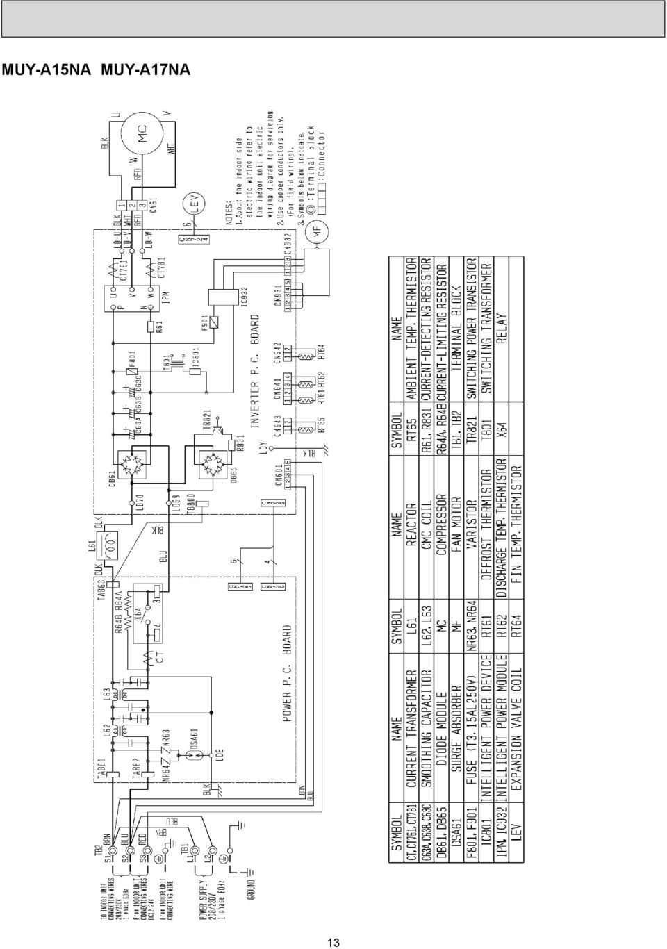
12 5 WIRING DIAGRAM MUZ-A09NA MUZ-A12NA MUZ-A15NA MUZ-A17NA 12

13 MUY-A15NA MUY-A17NA 13
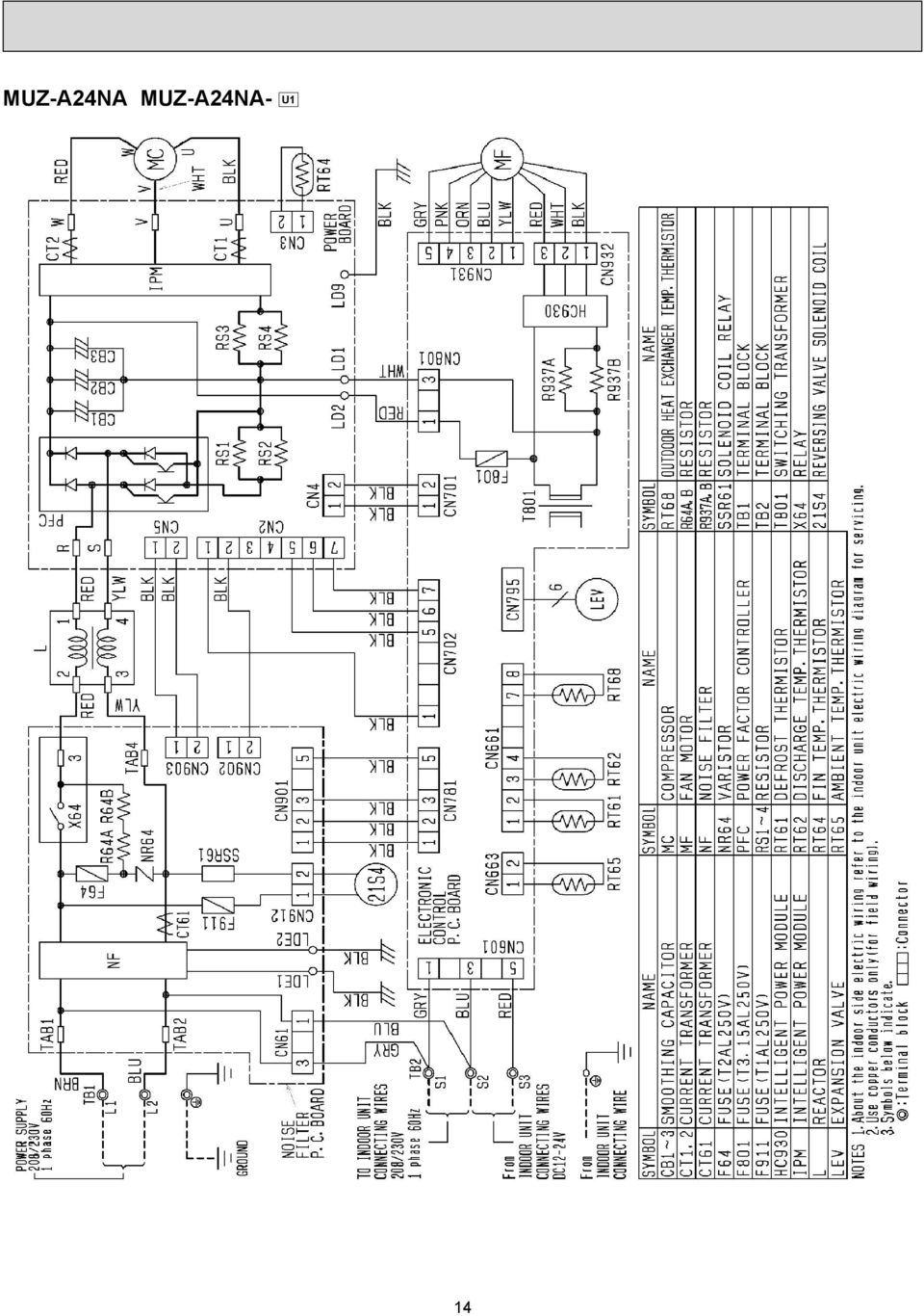
14 MUZ-A24NA MUZ-A24NA- U1 14
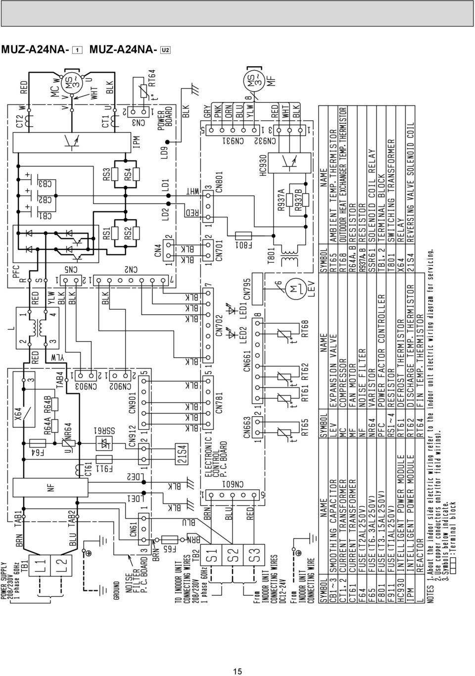
15 MUZ-A24NA- 1 MUZ-A24NA- U2 15
16 MUY-A24NA 16

17 MUY-A24NA- 1 17

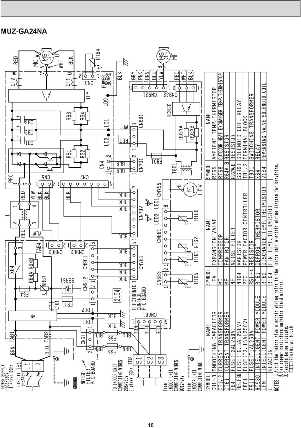
18 MUZ-GA24NA 18
19 MUY-GA24NA 19

20 6 REFRIGERANT SYSTEM DIAGRAM MUZ-A09NA MUZ-A09NA- U1 MUZ-A12NA MUZ-A15NA MUZ-A17NA MUY-A15NA MUY-A17NA Unit: inch Refrigerant pipe ø3/8 (MUZ-A09/12) ø1/2 (MUZ-A15/17,MUY-A15/17) (with heat insulator) 4-way valve Muffler Flared connection Flared connection Refrigerant pipe ø1/4 (with heat insulator) Stop valve (with service port) Muffler Stop valve (with strainer) Discharge temperature thermistor RT62 Service port Muffler Service port Compressor Defrost thermistor RT61 Capillary tube O.D I.D /8 (ø3.0 ø ) Expansion valve Outdoor heat exchanger Strainer #100 Ambient temperature thermistor RT65 R.V. coil heating ON cooling OFF Refrigerant flow in cooling Refrigerant flow in heating (MUZ) MUZ-A09NA- 1 MUZ-A09NA- U2 Refrigerant pipe ø3/8 (with heat insulator) Muffler 4-way valve Flared connection Stop valve (with service port) Discharge temperature thermistor RT62 Muffler Compressor Defrost thermistor RT61 Outdoor heat exchanger Ambient temperature thermistor RT65 Flared connection Refrigerant pipe ø1/4 (with heat insulator) Stop valve (with strainer) Expansion valve Capillary tube O.D I.D /16 (ø3.0 ø ) Muffler Strainer #100 R.V. coil heating ON cooling OFF Refrigerant flow in cooling Refrigerant flow in heating 20
 Expansion valve Outdoor heat exchanger Strainer #100 Ambient temperature thermistor RT65 R.V.")
21 MUZ-A24NA MUZ-GA24NA Unit: inch Refrigerant pipe ø5/8 (with heat insulator) 4-way valve Muffler #100 Flared connection Stop valve (with service port) Service port Discharge temperature thermistor RT62 Service port Defrost thermistor RT61 Outdoor heat exchanger Ambient temperature thermistor RT65 Flared connection Refrigerant pipe ø1/4 (with heat insulator) Stop valve Strainer Receiver #100 Compressor LEV Capillary tube O.D I.D /32 (ø3.6 ø2.4 50) Strainer #100 Outdoor heat exchanger temperature thermistor RT68 R.V. coil heating ON cooling OFF Refrigerant flow in cooling Refrigerant flow in heating MUY-A24NA MUY-GA24NA Refrigerant pipe ø5/8 (with heat insulator) 4-way valve Muffler #100 Flared connection Stop valve (with service port) Service port Discharge temperature thermistor RT62 Service port Outdoor heat exchanger Ambient temperature thermistor RT65 Flared connection Strainer Receiver #100 Compressor LEV Strainer #100 Outdoor heat exchanger temperature thermistor RT68 Refrigerant pipe ø1/4 (with heat insulator) Stop valve Capillary tube O.D I.D /32 (ø3.6 ø2.4 50) Refrigerant flow in cooling 21
22 MAX. REFRIGERANT PIPING LENGTH and MAX. HEIGHT DIFFERENCE Model MUZ-A09NA MUZ-A12NA MUZ-A15NA MUY-A15NA MUZ-A17NA MUY-A17NA MUZ-A24NA MUY-A24NA MUZ-GA24NA MUY-GA24NA Max. Length A Refrigerant piping: ft. Max. Height difference B Gas Piping size O.D: in. Liquid 3/8 1/4 1/2 1/ /8 1/4 Indoor unit Max. Height difference B Max. Length A Outdoor unit ADDITIONAL REFRIGERANT CHARGE (R410A: oz.) Refrigerant piping exceeding 25 ft. requires additional refrigerant charge according to the calculation. Model MUZ-A09NA MUZ-A09NA - U1 MUZ-A12NA MUZ-A09NA - 1 MUZ-A09NA - U2 MUZ-A15NA MUY-A15NA MUZ-A17NA MUY-A17NA Model MUZ-A24NA MUY-A24NA MUZ-GA24NA MUY-GA24NA Outdoor unit precharged 2 lb. 5 oz. 2 lb. 2 lb. 7 oz. Outdoor unit precharged Refrigerant piping length (one way): ft Calculation: X oz. = 1.62/5 oz. / ft. (Refrigerant piping length (ft.) - 25) Refrigerant piping length (one way): ft lb Calculation: X oz. = 1.08/5 oz. / ft. (Refrigerant piping length (ft.) - 25) NOTE: Refrigerant piping exceeding 25 ft. requires additional refrigerant charge according to the calculation. 22
23 7 DATA MUZ-A09NA MUZ-A12NA MUZ-A15NA MUZ-A17NA MUZ-A24NA MUZ-GA24NA MUY-A15NA MUY-A17NA MUY-A24NA MUY-GA24NA 7-1. PERFORMANCE DATA 1) COOLING CAPACITY Indoor air Outdoor intake air DB temperature ( F) Model IWB ( F) TC SHC TPC TC SHC TPC TC SHC TPC TC SHC TPC TC SHC TPC MUZ-A09NA MUZ-A09NA - U MUZ-A09NA MUZ-A09NA - U MUZ-A12NA MUY-A15NA MUZ-A15NA MUY-A17NA MUZ-A17NA MUY-A24NA MUZ-A24NA MUY-GA24NA MUZ-GA24NA NOTE: 1. IWB: Intake air wet-bulb temperature TC: Total Capacity ( 10 3 Btu/h) SHC: Sensible Heat Capacity ( 10 3 Btu/h) TPC: Total Power Consumption (kw) 2. SHC is based on 80 F of indoor Intake air DB temperature. 2) COOLING CAPACITY CORRECTIONS Model MSZ-A09/12/15/17NA MSY-A15/17NA MSZ-A24NA MSY-A24NA MSZ-GA24NA MSY-GA24NA Refrigerant piping length (one way: ft.) 25 (std.)
24 3) HEATING CAPACITY Model MUZ-A09NA MUZ-A09NA - U1 MUZ-A09NA - 1 MUZ-A09NA - U2 MUZ-A12NA MUZ-A15NA MUZ-A17NA MUZ-A24NA MUZ-GA24NA Indoor air Outdoor intake air WB temperature ( F) IDB ( F) TC TPC TC TPC TC TPC TC TPC TC TPC TC TPC TC TPC NOTE: 1. IDB: Intake air dry-bulb temperature TC: Total Capacity ( 10 3 Btu/h) TPC: Total Power Consumption (kw) 2. Above data is for heating operation without any frost. How to operate with fixed operational frequency of the compressor. 1. Press the EMERGENCY OPERATION switch on the front of the indoor unit, and select either EMERGENCY COOL mode or EMERGENCY HEAT mode before starting to operate the air conditioner. 2. The compressor starts with operational frequency. 3. The fan speed of the indoor unit is High. 4. This operation continues for 30 minutes. 5. In order to release this operation, press the EMERGENCY OPERATION switch twice or once, or press any button on the remote controller. 24
25 7-2. PERFORMANCE CURVE Cooling MUZ-A09NA MUZ-A09NA- U1 SHF at rating condition = 0.71 Airflow = 2 CFM MUZ-A09NA- 1 MUZ-A09NA- U2 SHF at rating condition = 0.71 Airflow = 2 CFM MUZ-A12NA SHF at rating condition = 0. Airflow = 318 CFM Total capacity ( 10 3 Btu/h) Indoor intake air WB temperature ( F) Total capacity ( 10 3 Btu/h) Indoor intake air WB temperature ( F) Total capacity ( 10 3 Btu/h) Indoor intake air WB temperature ( F) Total power consumption (kw) Indoor intake air WB temperature ( F) Outdoor intake air DB temperature ( F) Total power consumption (kw) Indoor intake air WB temperature ( F) Outdoor intake air DB temperature ( F) Indoor intake air WB temperature ( F) Outdoor intake air DB temperature ( F) MUZ-A15NA MUY-A15NA MUZ-A17NA MUY-A17NA MUZ-A24NA MUY-A24NA Total power consumption (kw) Total capacity ( 10 3 Btu/h) Total power consumption (kw) SHF at rating condition = 0.65 Airflow = 342 CFM Indoor intake air WB temperature ( F) Indoor intake air WB temperature ( F) Outdoor intake air DB temperature ( F) MUZ-GA24NA MUY-GA24NA Total capacity ( 10 3 Btu/h) Total power consumption (kw) SHF at rating condition = 0.65 Airflow = 342 CFM Indoor intake air WB temperature ( F) Indoor intake air WB temperature ( F) Outdoor intake air DB temperature ( F) Total capacity ( 10 3 Btu/h) Total power consumption (kw) SHF at rating condition = 0.63 Airflow = 508 CFM Indoor intake air WB temperature ( F) Indoor intake air WB temperature ( F) Outdoor intake air DB temperature ( F) SHF at rating condition = 0.63 Airflow = 508 CFM Total capacity ( 10 3 Btu/h) Indoor intake air WB temperature ( F) Total power consumption (kw) Indoor intake air WB temperature ( F) Outdoor intake air DB temperature ( F) Heating Total capacity ( 10 3 Btu/h) Total power consumption (kw) MUZ-A09NA MUZ-A09NA- U1 Airflow = 307 CFM Indoor intake air DB temperature ( F) Indoor intake air DB temperature ( F) Outdoor intake air WB temperature ( F) Total capacity ( 10 3 Btu/h) Total power consumption (kw) MUZ-A09NA- 1 MUZ-A09NA- U Airflow = 307 CFM Indoor intake air DB temperature ( F) Indoor intake air DB temperature ( F) Outdoor intake air WB temperature ( F) Total capacity ( 10 3 Btu/h) Total power consumption (kw) MUZ-A12NA Airflow = 318 CFM Indoor intake air DB temperature ( F) Indoor intake air DB temperature ( F) Outdoor intake air WB temperature ( F)
26 Total capacity ( 10 3 Btu/h) Total power consumption (kw) Total capacity ( 10 3 Btu/h) Total power consumption (kw) MUZ-A15NA MUZ-A17NA MUZ-A24NA Airflow= 381 CFM Indoor intake air DB temperature ( F) Indoor intake air DB temperature ( F) Outdoor intake air WB temperature ( F) MUZ-GA24NA Airflow = 568 CFM Indoor intake air DB temperature ( F) Indoor intake air DB temperature ( F) Outdoor intake air WB temperature ( F) Total capacity ( 10 3 Btu/h) Total power consumption (kw) Airflow = 381 CFM Indoor intake air DB temperature ( F) Indoor intake air DB temperature ( F) Outdoor intake air WB temperature ( F) Total capacity ( 10 3 Btu/h) Total power consumption (kw) Airflow = 568 CFM Indoor intake air DB temperature ( F) Indoor intake air DB temperature ( F) Outdoor intake air WB temperature ( F) This value of frequency is not the same as the actual frequency in operating. Refer to 7-5 and 7-6 for the relationships between frequency and capacity Condensing pressure Cooling Data is based on the condition of indoor humidity 50%. Air flow should be set to High speed. MUZ-A09NA MUZ-A09NA- U1 Condensing pressure (PSIG) Indoor DB temperature ( F) ( F) Outdoor ambient temperature (PSIG) ( F) Suction pressure Indoor DB temperature ( F) Outdoor ambient temperature 26
27 MUZ-A09NA- 1 MUZ-A09NA- U2 Condensing pressure MUZ-A12NA Condensing pressure (PSIG) (PSIG) Indoor DB temperature ( F) Indoor DB temperature ( F) ( F) Outdoor ambient temperature ( F) MUZ-A15NA MUY-A15NA Condensing pressure (PSIG) Outdoor ambient temperature Indoor DB temperature ( F) ( F) Outdoor ambient temperature (PSIG) ( F) Suction pressure (PSIG) ( F) Suction pressure Indoor DB temperature ( F) Outdoor ambient temperature Indoor DB temperature ( F) Outdoor ambient temperature (PSIG) ( F) Outdoor ambient temperature Suction pressure Indoor DB temperature ( F) 27
28 MUZ-A17NA MUY-A17NA (PSIG) 580 Condensing pressure Indoor DB temperature ( F) ( F) Outdoor ambient temperature Suction pressure (PSIG) Indoor DB temperature ( F) ( F) Outdoor ambient temperature MUZ-A24NA MUY-A24NA Condensing pressure (PSIG) MUZ-GA24NA MUY-GA24NA Indoor DB temperature ( F) ( F) (PSIG) 580 Outdoor ambient temperature (PSIG) ( F) Outdoor ambient temperature Suction pressure Indoor DB temperature ( F) 540 Condensing pressure Indoor DB temperature ( F) Suction pressure (PSIG) ( F) Outdoor ambient temperature ( F) Outdoor ambient temperature 28
29 Heating Data is based on the condition of outdoor humidity %. Air flow should be set to High speed. Data is for heating operation without any frost. MUZ-A09NA MUZ-A09NA- U1 (PSIG) (PSIG) Condensing pressure Indoor DB temperature( F) 58Hz 65 Suction pressure Indoor DB temperature ( F) 58Hz ( F) Outdoor ambient temperature Outdoor ambient temperature ( F) MUZ-A09NA- 1 MUZ-A09NA- U2 (PSIG) (PSIG) Condensing pressure Indoor DB temperature( F) 58Hz 60 Suction pressure Indoor DB temperature ( F) 58Hz ( F) Outdoor ambient temperature Outdoor ambient temperature ( F) MUZ-A12NA (PSIG) (PSIG) Condensing pressure Indoor DB temperature( F) 58Hz 65 Suction pressure Indoor DB temperature ( F) 58Hz ( F) Outdoor ambient temperature Outdoor ambient temperature ( F) 29
30 MUZ-A15NA (PSIG) 620 Condensing pressure Indoor DB temperature( F) Outdoor ambient temperature 58Hz ( F) (PSIG) 160 Suction pressure Indoor DB temperature ( F) Outdoor ambient temperature 58Hz ( F) MUZ-A17NA (PSIG) 620 Condensing pressure Indoor DB temperature( F) Outdoor ambient temperature 58Hz ( F) (PSIG) 160 Suction pressure Indoor DB temperature ( F) Outdoor ambient temperature 58Hz ( F) MUZ-A24NA (PSIG) Hz ( F) Outdoor ambient temperature Condensing pressure Indoor DB temperature( F) (PSIG) 160 Suction pressure Indoor DB temperature ( F) Outdoor ambient temperature 58Hz ( F) 30
31 MUZ-GA24NA Condensing pressure (PSIG) Indoor DB temperature( F) Outdoor ambient temperature 58Hz ( F) (PSIG) Hz Suction pressure Indoor DB temperature ( F) ( F) Outdoor ambient temperature 31
32 7-4. STANDARD OPERATION DATA Total Electrical circuit Refrigerant circuit Indoor unit Outdoor unit Model MUZ-A09NA MSZ-A12NA Item Unit Cooling Heating Cooling Heating Cooling Heating Capacity Btu/h 9,000 10,900 9,000 10,900 12,000 13,600 SHF Input kw ,1 1,160 Rated frequency Hz Indoor unit MSZ-A09NA MSZ-A12NA Power supply (V, Phase, Hz) 208 / 230, 1, / 230, 1, 60 Input kw Fan motor current A 0.18 / / 0.21 Outdoor unit MUZ-A09NA MUZ-A09NA- U1 MUZ-A09NA- 1 MUZ-A09NA- U2 MUZ-A12NA Power supply (V, phase, Hz) 208 / 230, 1, / 230, 1, 60 Input kw Comp. current A 2.80 / / / / / / 4.54 Fan motor current A 0.37 / / / 0.34 Condensing pressure PSIG Suction pressure PSIG Discharge temperature F Condensing temperature F Suction temperature F Comp. shell bottom temp F Ref. pipe length ft Refrigerant charge (R410A) 2 lb. 5 oz. 2 lb. 2 lb. 5 oz. Intake air temperature DB F WB F Discharge air temperature DB F WB F Fan speed (High) rpm 1,080 1,080 1,080 1,080 1,220 1,220 Airfl ow (High) CFM 2 (Wet) (Wet) (Wet) 353 Intake air temperature DB F WB F Fan speed rpm Airfl ow CFM 1,094 1,094 1,129 1,129 1,094 1,094 32
33 Total Electrical circuit Refrigerant circuit Indoor unit Outdoor unit Model MSZ-A15NA MSY-A15NA MSZ-A15NA MSZ-A17NA MSY-A17NA MSZ-A17NA Item Unit Cooling Heating Cooling Heating Capacity Btu/h 15,000 18,000 16,200 20,100 SHF Input kw Rated frequency Hz Indoor unit MSZ-A15NA, MSY-A15NA MSZ-A17NA, MSY-A17NA Power supply (V, Phase, Hz) 208 / 230, 1, / 230, 1, 60 Input kw Fan motor current A 0.31 / / 0.28 Outdoor unit MUZ-A15NA MUY-A15NA MUZ-A15NA MUZ-A17NA MUY-A17NA MUZ-A17NA Power supply (V, phase, Hz) 208 / 230, 1, / 230, 1, 60 Input kw Comp. current A 7.56 / / / / 8.98 Fan motor current A 0.42 / / 0.38 Condensing pressure PSIG Suction pressure PSIG Discharge temperature F Condensing temperature F Suction temperature F Comp. shell bottom temp F Ref. pipe length ft Refrigerant charge (R410A) - 2 lb. 7 oz. 2 lb. 7 oz. Intake air temperature DB F WB F Discharge air temperature DB F WB F Fan speed (High) rpm 1,300 1,300 1,300 1,300 Airfl ow (High) CFM 342 (Wet) (Wet) 381 Intake air temperature DB F WB F Fan speed rpm Airfl ow CFM 1,249 1,249 1,249 1,249 33
34 Total Electrical circuit Refrigerant circuit Indoor unit Outdoor unit Model MSZ-A24NA MSY-A24NA MSZ-A24NA MSZ-GA24NA MSY-GA24NA MSZ-GA24NA Item Unit Cooling Heating Cooling Heating Capacity Btu/h 22,000 23,200 22,000 23,200 SHF Input kw Rated frequency Hz Indoor unit MSZ-A24NA, MSY-A24NA MSZ-GA24NA, MSY-GA24NA Power supply (V, Phase, Hz) 208 / 230, 1, 60 Input kw Fan motor current A 0.52 / 0.47 Outdoor unit MUZ-A24NA MUY-A24NA MUZ-A24NA MUZ-GA24NA MUY-GA24NA MUZ-GA24NA Power supply (V, phase, Hz) 208 / 230, 1, 60 Input kw Comp. current A / / / / 8.43 Fan motor current A 0.80 / / / 0.59 Condensing pressure PSIG Suction pressure PSIG Discharge temperature F Condensing temperature F Suction temperature F Comp. shell bottom temp F Ref. pipe length ft. 25 Refrigerant charge (R410A) - 4 lb. Intake air temperature DB F WB F DB F Discharge air temperature WB F Fan speed (High) rpm 1,310 Airfl ow (High) CFM 385 (Wet) (Wet) 341 Intake air temperature DB F WB F Fan speed rpm Airfl ow CFM 1,729 1,660 34
35 7-5. CAPACITY AND INPUT CORRECTION BY INVERTER OUTPUT FREQUENCY MUZ-A09NA MUZ-A09NA - U1 Correction of Cooling capacity 1.5 Correction of Cooling total input 1.5 Correction of Heating capacity 2.0 Correction of Heating total input 2.0 Capacity correction factors Input correction factors Capacity correction factors (Hz) (Hz) (Hz) (Hz) The operational frequency of compressor The operational frequency of compressor The operational frequency of compressor The operational frequency of compressor Input correction factors MUZ-A09NA - 1 MUZ-A09NA - U2 Correction of Cooling capacity 1.5 Correction of Cooling total input 1.5 Correction of Heating capacity 2.0 Correction of Heating total input 2.0 Capacity correction factors Input correction factors Capacity correction factors (Hz) (Hz) (Hz) (Hz) The operational frequency of compressor The operational frequency of compressor The operational frequency of compressor The operational frequency of compressor Input correction factors MUZ-A12NA Correction of Cooling capacity 1.5 Correction of Cooling total input 1.5 Correction of Heating capacity 2.0 Correction of Heating total input 2.0 Capacity correction factors Input correction factors Capacity correction factors (Hz) (Hz) (Hz) (Hz) The operational frequency of compressor The operational frequency of compressor The operational frequency of compressor The operational frequency of compressor MUZ-A15NA MUY-A15NA 1.5 Correction of Cooling capacity Correction of Cooling total input MUZ-A15NA 1.5 Correction of Heating capacity Input correction factors Correction of Heating total input 1.5 Capacity correction factors Input correction factors Capacity correction factors Input correction factors (Hz) (Hz) (Hz) (Hz) The operational frequency of compressor The operational frequency of compressor The operational frequency of compressor The operational frequency of compressor 35
36 MUZ-A17NA MUY-A17NA 1.5 Correction of Cooling capacity Correction of Cooling total input 1.5 MUZ-A17NA 1.5 Correction of Heating capacity 1.5 Correction of Heating total input Capacity correction factors MUZ-A24NA MUY-A24NA 1.5 Correction of Cooling capacity Input correction factors Correction of Cooling total input 1.5 Capacity correction factors (Hz) (Hz) (Hz) (Hz) The operational frequency of compressor The operational frequency of compressor The operational frequency of compressor The operational frequency of compressor MUZ-A24NA 1.5 Correction of Heating capacity Input correction factors Correction of Heating total input 1.5 Capacity correction factors Capacity correction factors Input correction factors Capacity correction factors (Hz) (Hz) (Hz) (Hz) The operational frequency of compressor The operational frequency of compressor The operational frequency of compressor The operational frequency of compressor MUZ-GA24NA MUY-GA24NA Correction of Cooling capacity Input correction factors Correction of Cooling total input Capacity correction factors MUZ-GA24NA Correction of Heating capacity (Hz) (Hz) (Hz) (Hz) The operational frequency of compressor The operational frequency of compressor The operational frequency of compressor The operational frequency of compressor Input correction factors Input correction factors Correction of Heating total input TEST RUN OPERATION (How to operate fixed-frequency operation) 1. Press EMERGENCY OPERATION switch to COOL or HEAT mode (COOL: Press once, HEAT: Press twice). 2. Test run operation starts and continues to operate for 30 minutes. 3. Compressor operates at rated frequency in COOL mode or 58 Hz in HEAT mode. 4. Indoor fan operates at High speed. 5. After 30 minutes, test run operation finishes and EMERGENCY OPERATION starts (operation frequency of compressor varies). 6. To cancel test run operation (EMERGENCY OPERATION), press EMERGENCY OPERATION switch or any button on remote controller. 36
37 8 ACTUATOR CONTROL MUZ-A09NA MUZ-A12NA MUZ-A15NA MUZ-A17NA MUZ-A24NA MUY-A15NA MUY-A17NA MUY-A24NA MUZ-GA24NA MUY-GA24NA 8-1. OUTDOOR FAN MOTOR CONTROL The fan motor turns ON/OFF, interlocking with the compressor. [ON] The fan motor turns ON 5 seconds before the compressor starts up. [OFF] The fan motor turns OFF 15 seconds after the compressor has stopped running. 5 seconds 15 seconds ON Compressor Outdoor fan motor OFF ON OFF 8-2. R.V. COIL CONTROL(MUZ) Heating ON Cooling OFF Dry OFF NOTE: The 4-way valve reverses for 5 seconds right before start-up of the compressor. ON Compressor OFF <MUZ-A09/12/15/17> ON R.V.coil OFF Outdoor fan ON motor OFF <COOL> 5 seconds ON or OFF <MUZ-A24,MUZ-GA24> ON R.V.coil OFF ON or OFF <HEAT> 5 seconds ON or OFF ON or OFF 8-3. RELATION BETWEEN MAIN SENSOR AND ACTUATOR <MUZ-A09/12/15/17, MUY-A15/17> Sensor Purpose Compressor 37 LEV Actuator Outdoor fan motor R.V. coil Indoor fan motor Discharge temperature thermistor Protection Cooling: Coil frost prevention Indoor coil temperature thermistor Heating: High pressure protection Cooling: High pressure protection Defrost thermistor Heating: Defrosting Fin temperature thermistor Protection Ambient temperature thermistor Cooling: Low ambient temperature operation <MUZ-A24, MUY-A24, MUZ-GA24, MUY-GA24> Sensor Purpose Compressor LEV Actuator Outdoor fan motor R.V. coil Indoor fan motor Discharge temperature thermistor Protection Cooling: Coil frost prevention Indoor coil temperature thermistor Heating: High pressure protection Defrost thermistor (MUZ) Defrosting Fin temperature thermistor Protection Outdoor heat exchanger temperature High pressure protection Cooling: Low ambient temperature Ambient temperature thermistor operation
38 9 SERVICE FUNCTIONS MUZ-A09NA MUZ-A12NA MUZ-A15NA MUZ-A17NA CHANGE IN DEFROST SETTING <JS> When the JS wire of the outdoor Inverter P.C. board is cut/soldered, the defrost finish temperature is changed. (Refer to ) Defrost finish temperature F ( C) Jumper wire MUZ-A09/12NA MUZ-A15/17NA Soldered (Initial setting) 50 (10) 41 (5) JS ne (Cut) 55 (13) 46 (8) 10 TROUBLESHOOTING MUZ-A09NA MUZ-A12NA MUZ-A15NA MUZ-A17NA MUZ-A24NA MUY-A15NA MUY-A17NA MUY-A24NA MUZ-GA24NA MUY-GA24NA CAUTIONS ON TROUBLESHOOTING 1. Before troubleshooting, check the following 1) Check the power supply voltage. 2) Check the indoor/outdoor connecting wire for miswiring. 2. Take care of the following during servicing 1) Before servicing the air conditioner, be sure to turn OFF the main unit first with the remote controller, then after confirming the horizontal vane is closed, turn OFF the breaker and/or disconnect the power plug. 2) Be sure to turn OFF the power supply before removing the front panel, the cabinet, the top panel, and the electronic control P.C. board. 3) When removing the electrical parts, be careful of the residual voltage of smoothing capacitor. 4) When removing the electronic control P.C. board, hold the edge of the board with care NOT to apply stress on the components. 5) When connecting or disconnecting the connectors, hold the housing of the connector. DO NOT pull the lead wires. Lead wiring Housing point 3. Troubleshooting procedure 1) First, check if the OPERATION INDICATOR lamp on the indoor unit is flashing ON and OFF to indicate an abnormality. To make sure, check how many times the abnormality indication is flashing ON and OFF before starting service work. 2) Before servicing check that the connector and terminal are connected properly. 3) When the electronic control P.C. board seems to be defective, check the copper foil pattern for disconnection and the components for bursting and discoloration. 4) Refer to and
39 10-2. FAILURE MODE RECALL FUNCTION Outline of the function This air conditioner can memorize the abnormal condition which has occurred once. Even though LED indication listed on the troubleshooting check table (10-3.) disappears, the memorized failure details can be recalled. 1. Flow chart of failure mode recall function for the indoor/outdoor unit Operational procedure The cause of abnormality cannot be found because the abnormality does not recur. This figures show about MSZ-A09/12/15/17. Setting up the failure mode recall function Turn ON the power supply. <Preparation of the remote controller> While pressing both OPERATION SELECT button and TOO COOL button on the remote controller at the same time, press RESET button. First, release RESET button. And release the other two buttons after all LCD in operation display section of the remote controller is displayed after 3 seconds. Press OPERATE/STOP (ON/OFF) button of the remote controller (the set temperature is displayed) with the remote controller headed towards the indoor unit. 1 Does the left lamp of OPERATION INDICATOR lamp on the indoor unit blink at the interval of 0.5 seconds? Blinks: Either indoor or outdoor unit is abnormal. Beep is emitted at the same timing as the blinking of the left lamp of OPERATION INDICATOR lamp. 2 Judgment of indoor/outdoor abnormality (Blinks) Before blinking, does the left lamp of OPERATION INDICA- TOR lamp stay ON for 3 seconds? Stays ON for 3 seconds (without beep): The outdoor unit is abnormal. (OFF) 1. Regardless of normal or abnormal condition, a short beep is emitted once the signal is received. Indoor unit is normal. But the outdoor unit might be abnormal because there are some abnormalities that can not be recalled with this way. Confi rm if outdoor unit is abnormal according to the detailed outdoor unit failure mode recall function. (Refer to ) The indoor unit is abnormal. Check the blinking pattern, and confi rm the abnormal point with the indoor unit failure mode table. (Refer to indoor unit service manual.) Make sure to check at least two consecutive blinking cycles. 2 The outdoor unit is abnormal. Check the blinking pattern, and confi rm the abnormal point with the outdoor unit failure mode table. (Refer to ) Make sure to check at least two consecutive blinking cycles. 3 Releasing the failure mode recall function Release the failure mode recall function by the following procedures. Turn OFF the power supply and turn it ON again. Press RESET button of the remote controller. Repair the defective parts. Deleting the memorized abnormal condition After repairing the unit, recall the failure mode again according to "Setting up the failure mode recall function" mentioned above. Press OPERATE/STOP (ON/OFF) button of the remote controller (the set temperature is displayed) with the remote controller headed towards the indoor unit. Press EMERGENCY OPERATION switch so that the memorized abnormal condition is deleted. Release the failure mode recall function according to "Releasing the failure mode recall function" mentioned above. NOTE: 1. Make sure to release the failure mode recall function once it's set up, otherwise the unit cannot operate properly. 2. If the abnormal condition is not deleted from the memory, the last abnormal condition is kept memorized. 2. Blinking pattern when the indoor unit is abnormal: 2.5-second OFF Blinking at 0.5- second interval 2.5-second OFF Blinking at 0.5- second interval ON OFF Beeps Repeated cycle Beeps Repeated cycle Beeps Repeated cycle 3.Blinking pattern when the outdoor unit is abnormal: Blinking at second OFF 3-second ON second interval 2.5-second OFF 3-second ON Blinking at 0.5- second interval ON OFF beep Repeated cycle Beeps beep Repeated cycle Beeps Repeated cycle 39
SERVICE MANUAL MUZ-GE09NA MUZ-GE12NA MUZ-GE15NA MUZ-GE18NA MUZ-GE24NA MUY-GE09NA MUY-GE12NA MUY-GE15NA MUY-GE18NA MUY-GE24NA OUTDOOR UNIT
 SPLIT-TYPE AIR CONDITIONERS Revision B: Descriptions regarding the outdoor fan motor have been corrected. Please void OBH549 REVISED EDITION-A. OUTDOOR UNIT SERVICE MANUAL HFC utilized R410A. OBH549 REVISED
SERVICE MANUAL MUZ-FE09NA MUZ-FE12NA MUZ-FE18NA OUTDOOR UNIT. No. OBH543 REVISED EDITION-A. Models HFC
 SPLIT-TYPE AIR CONDITIONERS Revision A: MUZ-FE18NA has been added. Please void OBH543. OUTDOOR UNIT SERVICE MANUAL HFC utilized R410A. OBH543 REVISED EDITION-A Models MUZ-FE09NA MUZ-FE12NA MUZ-FE18NA Indoor
SERVICE MANUAL MUZ-GE25VA - E1 MUZ-GE25VAH - E1 MUZ-GE35VA - E1 MUZ-GE35VAH - E1 MUZ-GE42VA - E1 MUZ-GE42VAH - E1 MUZ-GE50VA - E1 MUZ-GE50VAH - E1
 SPLIT-TYPE AIR CONDITIONERS Revision A: MUZ-GE42/50VA(H) - E1 has been added. Please void OBH516. OUTDOOR UNIT SERVICE MANUAL HFC utilized R410A. OBH516 REVISED EDITION-A Models MUZ-GE25VA - E1 MUZ-GE25VAH
SERVICE MANUAL MU-A09WA MU-A12WA MU-A12WA- 1 OUTDOOR UNIT. No. OB449. Wireless type Models HFC. Revision : A SPLIT-TYPE AIR CONDITIONERS
 SPLIT-TYPE AIR CONDITIONERS Revision : A MU-AWA- Please void OB449. has been added. OUTDOOR UNIT SERVICE MANUAL Wireless type Models MU-AWA MU-AWA- HFC utilized R40A No. OB449 REVISED EDITION-A Indoor
SERVICE MANUAL OUTDOOR UNIT. No. OBH590 REVISED EDITION-B. Models HFC
 SPLIT-TYPE AIR CONDITIONERS Revision B: MUZ-EF25/35/42/50VE - E2 and MUZ-EF25/35VEH - E2 have been added. Please void OBH590 REVISED EDITION-A. OUTDOOR UNIT SERVICE MANUAL HFC utilized R410A. OBH590 REVISED
SERVICE MANUAL MXZ-2A20NA MXZ-2A20NA - MXZ-3A30NA MXZ-3A30NA - MXZ-4A36NA OUTDOOR UNIT. No. OB444. Models HFC. Inverter-controlled multi system type
 Revision C: MXZ-4A36NA have been added. SPLIT-TYPE, HEAT PUMP AIR CONDITIONERS Please void OB444 REVISED EDITION-B. OUTDOOR UNIT SERVICE MANUAL HFC utilized R40A No. OB444 REVISED EDITION-C Inverter-controlled
SERVICE MANUAL MUZ-HJ25VA MUZ-HJ35VA OUTDOOR UNIT. No. OBH648. Models HFC SPLIT-TYPE AIR CONDITIONERS R410A
 SPLIT-TYPE AIR CONDITIONERS OUTDOOR UNIT SERVICE MANUAL HFC utilized R410A. Models MUZ-HJ25VA MUZ-HJ35VA - E1 - E1 Indoor unit service manual MSZ-HJ VA Series (OBH647) MUZ-HJ25VA MUZ-HJ35VA CONTENTS 1.
SERVICE MANUAL INDOOR UNIT
 SPLIT-TYPE AIR CONDITIONERS Revision E: MSZ-GE22VAD- A1 has been added. Please void OBH531 REVISED EDITION-D. INDOOR UNIT SERVICE MANUAL. OBH531 REVISED EDITION-E Models MSZ-GE22VA - A1 MSZ-GE50VA - A1
HP switch LP switch Discharge thermo Comp. Surface thermo
 1 Specifications Zubadan Model Name PUHZ-SHW80VHA PUHZ-SHW11VHA PUHZ-SHW11YHA Power supply (phase, cycle, voltage) 1φ, V, Hz 1φ, V, Hz 3φ, 0V, Hz Max. current A 9.5 35.0 13.0 Breaker size A 3 16 Outer
technical data air conditioning systems RXS20-25-35E (single phase) FBQ-B8V1-B8V3B Split Heat Pump Condensing Units Split Sky Air
 FBQ-B8V1-B8V3B Split Heat Pump Condensing Units Split Sky Air") technical data RXS20-25-35E FBQ-B8V-B8V3B (single phase) Split Heat Pump Condensing Units air conditioning systems Split Sky Air Outdoor Units R-40A RXS-E2VB Split Sky Air Outdoor Units Features O u t
technical data RXS20-25-35E FBQ-B8V-B8V3B (single phase) Split Heat Pump Condensing Units air conditioning systems Split Sky Air Outdoor Units R-40A RXS-E2VB Split Sky Air Outdoor Units Features O u t
SERVICE MANUAL INDOOR UNIT
 SPLIT-TYPE AIR CONDITIONERS Revision B: "How to check miswiring and serial signal error" for MUZ type has been added. The description about "Low standby power control" has been added to "TECHNICAL CHANGES".
SERVICE MANUAL INDOOR UNIT. No. OB450. Models. Revision D: SPLIT-TYPE AIR CONDITIONERS REVISED EDITION-D
 Revision D: MSZ-GA NA and MSY-GA NA have been added. SPLIT-TYPE AIR CONDITIONERS Please void OB450 REVISED EDITION-C. INDOOR UNIT SERVICE MANUAL. OB450 REVISED EDITION-D Models MSZ-A09NA, - 1 MSZ-A12NA,
MU09TW MU12TN MU15TN MU17TN
 SPLIT-TYPE AIR CONDITIONERS SERVICE MANUAL Wireless type Models (W) MSTN (W) MS5TN (W) MS7TN (W) MU09TW MUTN MU5TN MU7TN No. OB74 CONTENTS MSTN MS5TN MS7TN INDOOR UNIT MU5TN MU7TN OUTDOOR UNIT Remote controller.
Air Conditioners Technical Data
 Air Conditioners Technical Data O u t d o o r U n i t E E D E N 2-0 0 RX-JV Outdoor Unit RX-JV TABLE OF CONTENTS RX-JV Features............................................................. 2 2 Specifications.......................................................
SERVICE MANUAL MSZ-HJ25VA MSZ-HJ35VA MSZ-HJ50VA INDOOR UNIT. No. OBH647. Models. Revision A: MSZ-HJ50VA- E1 has been added.
 SPLIT-TYPE AIR CONDITIONERS Revision A: MSZ-HJ50VA- E1 has been added. Please void OBH647. INDOOR UNIT SERVICE MANUAL. OBH647 REVISED EDITION-A Models MSZ-HJ25VA MSZ-HJ35VA MSZ-HJ50VA - E1 - E1 - E1 CONTENTS
SERVICE INSTRUCTION R410A. WALL MOUNTEDtype INVERTER SPLIT TYPE ROOM AIR CONDITIONER. Models Indoor unit Outdoor unit
 SERVICE INSTRUCTION SPLIT TYPE ROOM AIR CONDITIONER WALL MOUNTEDtype INVERTER Models Indoor unit Outdoor unit ASYG07LECA ASYG09LECA ASYG12LECA ASYG14LECA AOYG07LEC AOYG09LEC AOYG12LEC AOYG14LEC R410A CONTENTS
CONTENTS 1. IMPORTANT NOTICE 2 2. TECHNICAL SPECIFICATION 3 3. OPERATION DETAILS 4 4. ELECTRICAL SCHEMATIC DIAGRAM 13 5. EXPLOSION VIEW 16 6
 TCL WALL MOUNTED SPLIT-TYPE AIR CONDITIONERS SERVICE MANUAL No.TE080528 Models KFTHP-12 KFTHP-18 KFTHP-24 CONTENTS 1. IMPORTANT NOTICE 2 2. TECHNICAL SPECIFICATION 3 3. OPERATION DETAILS 4 4. ELECTRICAL
Split-type Air-Conditioner INSTALLATION MANUAL CONTENTS FOR INSTALLER MXZ-3A30NA MXZ-4A36NA ATTENTION. English. Français. Español
 Split-type Air-Conditioner MXZ-3A30NA MXZ-4A36NA INSTALLATION MANUAL Refer to the installation manual of each indoor unit for indoor unit installation. English Français Español ATTENTION This manual mentions
CONTENTS 1. IMPORTANT NOTICE 2 2. TECHNICAL SPECIFICATION 3 3. OPERATION DETAILS 4 4. WIRING DIAGRAM 11 5. EXPLOSION VIEW 12 6.
 TCL WALL MOUNTED SPLIT-TYPE AIR CONDITIONERS SERVICE MANUAL No.TE051220 Models TAC-09CHSA/GI TAC-12CHSA/GI CONTENTS 1. IMPORTANT NOTICE 2 2. TECHNICAL SPECIFICATION 3 3. OPERATION DETAILS 4 4. WIRING DIAGRAM
SERVICE MANUAL MUZ-GC25VA - MUZ-GC25VAH - MUZ-GC35VA - MUZ-GC35VAH - E1 OUTDOOR UNIT. No. OBH469. Wireless type Models HFC
 SPLIT-TYPE, HEAT PUMP AIR CONDITIONERS OUTDOOR UNIT SERVICE MANUAL Wireless type Models E1 - E1 H - E1 - - E1 HFC utilized R410A. OBH469 Indoor unit service manual MSZ-GC VA Series (OBH468) H CONTENTS
SERVICE MANUAL INDOOR UNIT MSZ-EF35VEW MSZ-EF22VEB - - E1 MSZ-EF25VEB E1 MSZ-EF35VEB - - E1 MSZ-EF35VEB E1 MSZ-EF35VES - E1 - E1 MSZ-EF22VEW -
 SPLIT-TYPE AIR CONDITIONERS Revision A: Airflow in the Silent mode in the cooling operation has been changed. "TROUBLESHOOTING" has been corrected. Please void OBH589. INDOOR UNIT SERVICE MANUAL. OBH589
14. Troubleshooting Guide
 14. Guide 14.1 Refrigeration Cycle System In order to diagnose malfunctions, ensure the air conditioner is free from electrical problems before inspecting the refrigeration cycle. Such problems include
SERVICE MANUAL SPLIT SYSTEM ROOM AIR CONDITIONER SHARP CORPORATION SHARP CORPORATION CONTENTS
 SERVICE MANUAL SPLIT SYSTEM ROOM AIR CONDITIONER INDOOR UNIT AH-129 AH-MP14 OUTDOOR UNIT AU-129 AU-MP14 CONTENTS SPECIFICATIONS...2 EXTERNAL DIMENSIONS...4 WIRING DIAGRAMS...5 ELECTRICAL PARTS...6 MICROCOMPUTER
Service manual. Website: www.andico.com.au CAUTION - BEFORE SERVICING THE UNIT, READ THE SAFETY - PRECAUTIONS IN THIS MANUAL.
 Website: www.andico.com.au Service manual CAUTION - BEFORE SERVICING THE UNIT, READ THE SAFETY - PRECAUTIONS IN THIS MANUAL. - ONLY FOR AUTHORISED SERVICE PERSONNEL. MODELS: MPK1-09CR-QB8 MPK1-12ER-QB6
MAC-120HE-01 Air-Cooled Chiller
 MAC-120HE-01 Air-Cooled Chiller 10 Ton / 120,000 BTUH Air-Cooled Chiller 208/230-1-50/60 1 HVAC Guide Specifications Air-Cooled Liquid Chiller Nominal Size: 10 Tons Multiaqua Model Number: MAC-120HE-01
Indoor coil is too warm in cooling mode or too cold in heating mode. Reversing valve or coil thermistor is faulty
 Codes Room Air Conditioner range: Indoor unit alarm s If timer lamp flashes for 1 second on, 1 second off, this indicates pre heating on the coil during heating mode and is not an error. If timer lamp
DC INVERTER SPLIT SYSTEM AIR CONDITIONER
 TECHNICAL & SERVICE MANUAL CSKE1NB41 & CZ18BT1U + CUKE1NK1 CSKE18NB4UW & CZ18BT1U + CUKE18NKU DC INVERTER SPLIT SYSTEM AIR CONDITIONER Indoor Model No. Body (Panel) CSKE1NB41 (CZ18BT1U) CSKE18NB4UW (CZ18BT1U)
Failure code manual. content
 Failure code manual content 一 wall split AC series 2 二 floor standing AC series. 4 三 portable AC series.. 5 四 dehumidifer 6 五 DC inverter single split series...7 六 DC inverter multi-split series 10 1 一
USER S MANUAL HSC-24A
 AIRREX AIR CONDITIONER USER S MANUAL HSC-24A Thank you for purchasing an AIRREX AIR CONDITIONER. BEFORE operation please read this user s manual carefully. Keep this manual readily available. It is ESSENTIAL
Si10-417_C. Pocket Manual. Service Diagnosis SPLIT & MULTI
 Pocket Manual Service Diagnosis SPLIT & MULTI Service Diagnosis SPLIT & MULTI 1. Troubleshooting with LED...5 1.1 Indoor Unit... 5 1.2 Outdoor Unit... 10 2. Troubleshooting by Symptoms...11 2.1 Air conditioner
SERVICE INSTRUCTION R410A. WALL MOUNTEDtype SPLIT TYPE ROOM AIR CONDITIONER INVERTER. Models Indoor unit Outdoor unit AOU 9RLFW AOU12RLFW AOU15RLS
 SERVICE INSTRUCTION SPLIT TYPE ROOM AIR CONDITIONER WALL MOUNTEDtype INVERTER Models Indoor unit Outdoor unit ASU 9RLF ASURLF ASU5RLS AOU 9RLFW AOURLFW AOU5RLS R40A CONTENTS. DESCRIPTION OF EACH CONTROL
PANASONIC TROUBLE SHOOTING GUIDE
 A General Guide To Room Style Products Pipework Pipe sizes and lengths should be as the relevant Technical Guide Both lines should be insulated No line accessories or oil traps should be fitted In cooling
TECHNICAL & SERVICE MANUAL SPLIT SYSTEM AIR CONDITIONER + SAP C181MA + SAP C181GA + SAP C181BA + SAP C241MA + SAP C241BA FILE NO.
 TECHNICAL & SERVICE MANUAL SAP K161GJA SAP K181GJA SAP K181MBA SAP K241GJA SAP K241MBA + SAP C161GA + SAP C161JA + SAP C181GA + SAP C181JA + SAP C181MA + SAP C181BA + SAP C241GA + SAP C241JA + SAP C241MA
DC INVERTER SPLIT SYSTEM AIR CONDITIONER
 TECHNICAL & SERVICE MANUAL CSKS12NB41 & CZ18BT1U + CUKS12NK1A CSKS18NB4UW & CZ18BT1U + CUKS18NKU CSKS18NB4UW & CZ18BT1U + CUKS18NKUA DC INVERTER SPLIT SYSTEM AIR CONDITIONER Indoor Model No. Body (Panel)
Operating Instructions Split System Air Conditioner
 Operating Instructions Split System Air Conditioner Model No. Indoor Unit Type Indoor Unit Type Nominal Capacity 26 36 F2 Low Silhouette Ducted S-26PF2U6 S-36PF2U6 Connectable outdoor unit lineup This
Air Conditioners. Technical Data. Wall Mounted Unit. www.daikin.eu RX-JV/GV
 Air Conditioners Technical Data Wall Mounted Unit www.daikin.eu RX-JV/GV Air Conditioners Technical Data Wall Mounted Unit www.daikin.eu RX-JV/GV TABLE OF CONTENTS RX-JV/GV 1 Features.............................................................
Air Conditioner Water Heater - A Product of HotSpot Energy LLC
 Air Conditioner Water Heater - A Product of HotSpot Energy LLC PLEASE READ THIS BEFORE YOU INSTALL THE UNIT 1. This air conditioner must be installed and/or repaired by a qualified technician. If you perform
Portable Air Conditioner
 Portable Air Conditioner Owner's Manual Model:3 in 1 12,000 Btu/h Series 3 Please read this owner s manual carefully before operation and retain it for future reference. CONTENTS 1. SUMMARY...1 2. PORTABLE
york air-conditioning products Residential & VRF News 2015
 york air-conditioning products Residential & VRF News 2015 york air-conditioning products Catalogue Content Split Systems Pag. High wall High Efficiency Inverter YWHJZH 09 to 24 K 6 High wall Inverter
New Deluxe Wall Mounted Heat Pump Series EXTERIOS
 New Deluxe Wall Mounted Heat Pump Series EXTERIOS May 2013 New Deluxe Wall Mounted Heat Pump Series Panasonic Adding New Air Conditioner Lineup Setting Another Mile Stone in the US Ductless Split History
Model: AC-S13CG x 2. Model No: AC-S13CGx2.doc Version 1.0
 Air Conditioner Service Manual 2 3 Model: AC-S13CG x 2 3 Content Technical specification.. 4 Performance curve.5 Outline & dimension of indoor unit..10 Outline & dimension of outdoor unit 11 Exploded view
NewAir AC-10100E / AC-10100H Portable Air Conditioner Owner s Manual PLEASE READ AND SAVE THESE INSTRUCTIONS
 NewAir AC-10100E / AC-10100H Portable Air Conditioner Owner s Manual PLEASE READ AND SAVE THESE INSTRUCTIONS ELECTRICAL SAFETY This appliance is for indoor use only. Always turn off the unit and unplug
M SERIES REFRIGERANT COIL MODULE REFRIGERANT COILS for R-22, R-407C, R-410A
 Bulletin 20-20.2 / July 2012 M SERIES REFRIGERANT COIL MODULE REFRIGERANT COILS for R-22, R-407C, R-410A ➀ ➁ ➂ Model Number Key M 2430 C L 1 - A - ➀ Unit Type M=Modular Nominal Capacity 2430=24000 to 30000
evo+ Installation, Service & Troubleshooting DUCTLESS SYSTEM
 evo+ DUCTLESS SYSTEM Installation, Service & Troubleshooting Models: GWH09AB-A3DNA2B GWH12AB-A3DNA2B GWH09AB-D3DNA2D GWH12AB-D3DNA2D GWH18AB-D3DNA2D GWH24AB-D3DNA2D Table of Contents Safety Precautions
ECOCIAT. Domestic hot water heat recovery unit
 Heat recovery unit Domestic hot water High energy efficiency with R410A Compact and quiet Scroll compressors Brazed-plate heat exchangers Heating Heat recovery ENVIRONMENTALLY HFC R410A PROTECTION DE FRIENDLY
DC INVERTER MULTI-SYSTEM AIR CONDITIONER
 TECHNICAL & SERVICE MANUAL OUTDOOR UNIT : AEMI0AH AEMIAHB AEMIAH AEMI0AH FILE NO. Destination: Europe DC INVERTER MULTI-SYSTEM AIR CONDITIONER Capacity.0k.k.k.0k Outdoor Model No. AEMI0AH AEMIAHB AEMIAH
DC INVERTER MULTI-SYSTEM AIR CONDITIONER
 TECHNICAL & SERVICE MANUAL OUTDOOR UNIT : CM97 CM7 CM7 FILE NO. Destination: North America DC INVERTER MULTI-SYSTEM AIR CONDITIONER Capacity at 0V 9,700 BTU/h,00 BTU/h 0,600 BTU/h Outdoor Model No. CM97
AIR CONDITIONER INSTALLATION MANUAL
 INSTALLATION MANUAL AIR CONDITIONER Please read this installation manual completely before installing the product. Installation work must be performed in accordance with the national wiring standards by
LG Air Conditioning - Universal Split Fault Codes Sheet. Universal Split Systems
 Universal Split Systems If there is a fault on any LG Universal unit, a two digit number will appear on the remote controllers led display. If the unit does not have a remote controller the fault will
ROOFTOP - HEAT PUMP UNIT. This document applies when installing into an air handler or as part of an air handling system.
 ROOFTOP - HEAT PUMP UNIT Technical data Applies to Model YNRA R410A This document applies when installing into an air handler or as part of an air handling system. CONTENTS 1. General description... 2
AIR-CONDITIONER SPLIT TYPE
 FILE NO. A08-016 SERVICE MANUAL AIR-CONDITIONER SPLIT TYPE RAS-M10PKVP-E, RAS-M13PKVP-E, RAS-M16PKVP-E, RAS-M18PKVP-E / RAS-M10PKVP-ND, RAS-M13PKVP-ND, RAS-M16PKVP-ND, RAS-M18PKVP-ND / RAS-3M26GAV-E1,
CS-XE9EKE CU-XE9EKE CS-XE12EKE CU-XE12EKE
 Order No. MAC0512111C8 Air Conditioner CS-XE9EKE CU-XE9EKE CS-XE12EKE CU-XE12EKE TABLE OF CONTENTS PAGE 1 Safety Precautions----------------------------------------------- 3 2 Specifications -----------------------------------------------------
CLOSE CONTROL SYSTEM. PFD series provide you with highly reliable computer room cooling system. High Reliability
 PFD-P250VM-E PUHY-P250YJM-A(-BS) PUHY-P500YSJM-A(-BS) PQHY-P250YHM-A CLOSE CONTROL SYSTEM MITSUBISHI ELECTRIC s Close Control System (PFD series) is specifically designed for computer rooms, laboratories
Appendix - Controllers 179
 Version: 200703 Appendix - Controllers 179 -3- -4- -5- -6- -7- -8- 2. Specifications 2.1 Specifications for inverter units item Model AB182ACERA Function cooling heating Capacity kw 5.01.8--5.8 5.22.0---6.2
CS-CE9NKE CS-CE12NKE CU-CE9NKE CU-CE12NKE TABLE OF CONTENTS WARNING
 Order No: PAPAMY1207094CE Indoor Unit CS-CE9NKE CS-CE12NKE Outdoor Unit CU-CE9NKE CU-CE12NKE WARNING This service information is designed for experienced repair technicians only and is not designed for
SERVICE MANUAL. Room Air Conditioner Multi Split Wall-Mounted Type Indoor. FSAI-Pro-91AE2 FSAI-Pro-121AE2 FSAIF-Pro-181AE2
 SERVICE MANUAL Room Air Conditioner Multi Split Wall-Mounted Type Indoor FSAI-Pro-91AE2 FSAI-Pro-121AE2 FSAIF-Pro-181AE2 NOTE: Before servicing the unit, please read this at first. Always contact with
DESIGN & TECHNICAL MANUAL
 AIR CONDITIONER Wall Mounted type DESIGN & TECHNICAL MANUAL INDOOR AS G07LECA AS G09LECA AS G12LECA AS G14LECA OUTDOOR AO G07LEC AO G09LEC AO G12LEC AO G14LEC 1. INDOOR UNIT : AS G07LECA AS G09LECA AS
TECHNICAL DATA & SERVICE MANUAL SPLIT SYSTEM AIR CONDITIONER INDOOR UNIT: AW52AL AW64AL AW52AL 387030095 AW64AL 0.8180.463.0 07/05
 TECHNICAL DATA & SERVICE MANUAL INDOOR UNIT: AW52AL AW64AL SPLIT SYSTEM AIR CONDITIONER Model No. Product Code No. AW52AL 387030095 AW64AL 387030096 0.8180.463.0 07/05 IMPORTANT! Please read before installation
SERVICE INSTRUCTION R410A. SPLIT TYPE ROOM AIR CONDITIONER Universal Floor / Ceiling Duct / Cassette Wall Mounted / Floor type INVERTER MULTI
 SERVICE INSTRUCTION SPLIT TYPE ROOM AIR CONDITIONER Universal Floor / Ceiling Duct / Cassette Wall Mounted / Floor type INVERTER MULTI R410A Models Indoor unit Outdoor unit AB*14LBAJ AB*18LBAJ AB*F14LAT
SECTION 23 81 03 - PACKAGED ROOFTOP AIR CONDITIONING UNITS NON-CUSTOM
 SECTION 23 81 03 - PACKAGED ROOFTOP AIR CONDITIONING UNITS NON-CUSTOM PART 1 - GENERAL 1.1 SUMMARY A. Section Includes: 1. Packaged rooftop air conditioning unit (5 tons and smaller). 2. Roof curb. 1.2
USER S MANUAL FH052EAV1 FH070EAV1. System Air Conditioner (Cooling and Heating) ENGLISH ESPAÑOL FRANÇAIS ITALIANO PORTUGUÊS DEUTSCH E HNIKA
 ENGLISH ESPAÑOL FRANÇAIS ITALIANO PORTUGUÊS DEUTSCH E HNIKA") USER S MANUAL FH052EAV1 FH070EAV1 E HNIKA PORTUGUÊS ENGLISH ESPAÑOL ITALIANO DEUTSCH FRANÇAIS System Air Conditioner (Cooling and Heating) E S F I P D G DB98-29263A(1) Safety Precautions Register your
USER S MANUAL FH052EAV1 FH070EAV1 E HNIKA PORTUGUÊS ENGLISH ESPAÑOL ITALIANO DEUTSCH FRANÇAIS System Air Conditioner (Cooling and Heating) E S F I P D G DB98-29263A(1) Safety Precautions Register your
TECHNICAL & SERVICE MANUAL WINDOW TYPE AIR CONDITIONER SA 79G SA 99G FILE NO. SA 79G SA 99G REFERENCE NO. SM700402
 TECHNICAL & SERVICE MANUAL SA 79G SA 99G FILE NO. WINDOW TYPE AIR CONDITIONER Model No. Product Code No. Destination SA-79G-A 1 851 005 18 General (50Hz) & Europe SA-99G-A 1 851 005 19 SA 79G SA 99G REFERENCE
SiUS091133. Service Manual. Inverter Pair FTXS-L Series FDXS-L Series. [Applied Models] Inverter Pair : Cooling Only Inverter Pair : Heat Pump
![SiUS091133. Service Manual. Inverter Pair FTXS-L Series FDXS-L Series. [Applied Models] Inverter Pair : Cooling Only Inverter Pair : Heat Pump](/thumbs/31/15338881.jpg "SiUS091133. Service Manual. Inverter Pair FTXS-L Series FDXS-L Series. [Applied Models] Inverter Pair : Cooling Only Inverter Pair : Heat Pump") Service Manual Inverter Pair FTXS-L Series FDXS-L Series [Applied Models] Inverter Pair : Cooling Only Inverter Pair : Heat Pump Inverter Pair FTXS-L Series FDXS-L Series Cooling Only Indoor Unit FTXS30LVJU
Service Manual Inverter Pair FTXS-L Series FDXS-L Series [Applied Models] Inverter Pair : Cooling Only Inverter Pair : Heat Pump Inverter Pair FTXS-L Series FDXS-L Series Cooling Only Indoor Unit FTXS30LVJU
Service Facts. WARNING: HAZARDOUS VOLTAGE - DISCONNECT POWER and DISCHARGE 4TTM3-SF-1. Split System Cooling 4TTM3018-4TTM3060
 4TTM3-SF-1 Service Facts Split System Cooling 4TTM3018-4TTM3060! CAUTION UNIT CONTAINS R-410A REFRIGERANT! R-410A OPERATING PRESSURE EXCEEDS THE LIMIT OF R-22. PROPER SERVICE EQUIPMENT IS REQUIRED. FAILURE
AquaFREE System. Technical Catalogue. Outdoor units: RAS-(3~5)HVRNE RAS-(4/5)HRNE. Indoor units: RWM-(3~5)FSN1E RWM-(3~5)FSN1E-(4.
HVRNE RAS-(4/5)HRNE. Indoor units: RWM-(3~5)FSN1E RWM-(3~5)FSN1E-(4.") AquaFREE System Technical Catalogue Outdoor units: RAS-(3~5)HVRNE RAS-(4/5)HRNE Indoor units: RWM-(3~5)FSN1E RWM-(3~5)FSN1E-(4.5/6)H(1/3) Specifications in this manual are subject to change without notice
AquaFREE System Technical Catalogue Outdoor units: RAS-(3~5)HVRNE RAS-(4/5)HRNE Indoor units: RWM-(3~5)FSN1E RWM-(3~5)FSN1E-(4.5/6)H(1/3) Specifications in this manual are subject to change without notice
DC INVERTER SPLIT SYSTEM AIR CONDITIONER
 AIR CONDITIONER TECHNICAL & SERVICE MANUAL CS-KS30NKU + CU-KS30NKUA CS-KS36NKU + CU-KS36NKUA DC INVERTER SPLIT SYSTEM AIR CONDITIONER Indoor Model No. CS-KS30NKU CS-KS36NKU Product Code No. 852 360 86
CU-2E15LBE CU-2E18LBE CU-3E18LBE CU-4E23LBE
 Order No. PHAAM1003090C3 Outdoor Unit CU-2E15LBE CU-2E18LBE CU-3E18LBE CU-4E23LBE Air Conditioner Please file and use this manual together with the service manual for Model No. CS-E7LKEW CU-E7LKE CS-E7LKEW
DUCTLESS MINI-SPLITS SINGLE & MULTI-ZONE HORIZONTAL AIR CONDITIONERS PORTABLE UNITS FREE MATCH COMPONENTS
 DUCTLESS MINI-SPLITS SINGLE & MULTI-ZONE HORIZONTAL AIR CONDITIONERS PORTABLE UNITS FREE MATCH COMPONENTS AN EXCELLENT CHOICE IN COOLING, COMFORT AND CONVENIENCE Why choose a Mini-Split system? Installing
INSTALLATION INSTRUCTIONS Fan Coil Replacement Coil Kit EBX & EBXX
 Fan Coil Replacement Coil Kit EBX & EBXX These instructions must be read and understood completely before attempting installation. These instructions covers the installation of replacement coil kit into
innovative comfort solutions
 engineering and specifications Guide duct-free air conditioning systems Art cool inverter flex multi-split floor standing ceiling cassette PTAC PTHP through-the-wall innovative comfort solutions 1 AT LG,
NewAir AC-10000E, AC-10000H Portable Air Conditioner Owner s Manual PLEASE READ AND SAVE THESE INSTRUCTIONS
 NewAir AC-10000E, AC-10000H Portable Air Conditioner Owner s Manual PLEASE READ AND SAVE THESE INSTRUCTIONS BEFORE USE GENERAL SAFETY INSTRUCTIONS: ALWAYS OPERATE THE UNIT IN AN UPRIGHT POSITION AND PLACE
SiUS041111. Service Manual. Inverter Pair Wall Mounted Type K-Series. [Applied Models] Inverter Pair : Cooling Only Inverter Pair : Heat Pump
![SiUS041111. Service Manual. Inverter Pair Wall Mounted Type K-Series. [Applied Models] Inverter Pair : Cooling Only Inverter Pair : Heat Pump](/thumbs/27/9681492.jpg "SiUS041111. Service Manual. Inverter Pair Wall Mounted Type K-Series. [Applied Models] Inverter Pair : Cooling Only Inverter Pair : Heat Pump") Service Manual Inverter Pair Wall Mounted Type K-Series [Applied Models] Inverter Pair : Cooling Only Inverter Pair : Heat Pump Inverter Pair Wall Mounted Type K-Series Cooling Only Indoor Unit FTXN09KEVJU
Service Manual Inverter Pair Wall Mounted Type K-Series [Applied Models] Inverter Pair : Cooling Only Inverter Pair : Heat Pump Inverter Pair Wall Mounted Type K-Series Cooling Only Indoor Unit FTXN09KEVJU
Multi System. 16 SEER, Inverter System. 9,000 to 18,000 BTU/Hr. Single Split
 Multi System 16 SEER, Inverter System 9,000 to 18,000 BTU/Hr Single Split 4MXW8-A 4TXM6-A March2013 42 Warnings and Cautions Warnings and Cautions. Notice that warnings and cautions appear at appropriate
Glossary of Heating, Ventilation and Air Conditioning Terms
 Glossary of Heating, Ventilation and Air Conditioning Terms Air Change: Unlike re-circulated air, this is the total air required to completely replace the air in a room or building. Air Conditioner: Equipment
ModPac II 1 to 5-Ton Vertical Wall Mount Air Conditioners Models AVPA12-20-24-30-36-42-48-60
 ModPac II 1 to 5-Ton Vertical Wall Mount Air Conditioners Models AVPA12-20-24-30-36-42-48-60 General Description The Marvair ModPac II air conditioner is a vertical, wall mounted, cost effective air conditioner
Split Type Inverter Room Air Conditioner OPERATION MANUAL
 Split Type Inverter Room Air Conditioner OPERATION MANUAL MODELS: AY-X09NCJ AE-X09NCJ AY-X12NCJ AE-X12NCJ AY-X18NCJ AE-X18NCJ AY-X24NCJ AE-X24NCJ AY-X28NCJ AE-X28NCJ Thank you for selecting SHARP Air-Conditioner.
SERVICE MANUAL MSZ-A18YV - E1 MSZ-A24YV - MSZ-A24YV - E1 INDOOR UNIT. No. OB345 REVISED EDITION-A. Models. Revision A : SPLIT-TYPE AIR CONDITIONERS
 SPLIT-TYPE AIR CONDITIONERS INDOOR UNIT SERVICE MANUAL Models E MSZ-A8YV - E MSZ-AYV - MSZ-A6YV - E Revision A : Parts numbers of indoor fan motor and motor band have been changed. Another type of the
How To Measure Temperature On A Thermostat
 Кондиционеры Mitsubishi Heavy Техническое руководство Кондиционеры настенного типа SRK20HD-S, SRK28HD-S, SRK40HD-S, SRK20CD-S, SRK28CD-S, SRK40CD-S CTENTS 1. GENERAL INFORMATI... 1 1.1 Specific features...
DC INVERTER SPLIT SYSTEM AIR CONDITIONER
 TECHNICAL & SERVICE MANUAL SAP-KRV9AEH + SAP-CRV9AEH SAP-KRV12AEH + SAP-CRV12AEH FILE NO. Destination: Europe DC INVERTER SPLIT SYSTEM AIR CONDITIONER Indoor Model No. SAP-KRV9AEH SAP-KRV12AEH Product
1. BEFORE INSTALLATION
 ENGLISH SPLIT-TYPE AIR CONDITIONERS INSTALLATION MANUAL JG79A191H03 MSZ-GE06/09/12/15/18NA MSY-GE09/12/15/18NA When installing multi units, refer to the installation manual of the multi unit for outdoor
Wall Mounted Mini Split Heat Pump Air Conditioner
 Wall Mounted Mini Split Heat Pump Air Conditioner OPERATING AND INSTALLATION MANUAL Model: KFIHP-09-ID / KFHIP-09-OD KFHHP-12-ID / KFHHP-12-OD Indoor Unit. Outdoor Unit. Thank you for selecting Soleus
SWIMMING POOL HEAT PUMP
 SWIMMING POOL HEAT PUMP Installation & User Manual Model HP40B HP50B HP65B Hayward Pool Products Canada, Inc. T: 1-888-238-7665 www.haywardpool.ca CONTENT I. Application 4 II. Features 4 III. Technical
R22. K Control. Indoor Unit. Nomenclature. Compatibility PL H 3 G K H B. Unit style Heat Pump Horse Power
 R22. K Control. Indoor Unit. Nomenclature. PL H 3 G K H B Compatibility Unit style Heat Pump Horse Power Control Boost Heaters R22. K Control. Outdoor Unit. Nomenclature. PU H 3 Y K A Compatibility Outdoor
SERVICE MANUAL. Room Air Conditioner Multi Split type Outdoor unit /R410A DC Inverter/
 SERVICE MANUAL Room Air Conditioner Multi Split type Outdoor unit /R410A DC Inverter/ FS2MI-147HFD FS2MI-187HFD FS3MI-217HFD FS3MI-277HFD FS4MI-277HFD FS4MI-367HFD FS5MI-367HFD NOTE: Before servicing the
CS-HE9NKE CS-HE12NKE CS-AE9NKE CU-HE9NKE CU-HE12NKE CU-AE9NKE TABLE OF CONTENTS WARNING
 Order No: PAPAMY1207093CE Indoor Unit CS-HE9NKE CS-HE12NKE CS-AE9NKE Outdoor Unit CU-HE9NKE CU-HE12NKE CU-AE9NKE WARNING This service information is designed for experienced repair technicians only and
REFRIGERATED TYPE COMPRESSED AIR DRYERS INSTRUCTION MANUAL. For Sales & Service please contact:
 7610.478.16 8/99 INSTRUCTION MANUAL Models 8005, 8010, 8015 For Sales & Service please contact: CENTRAIR Air Systems & Supplies Phone: 705-722-5747 Fax: 705-722-5458 Email: sales@centrair.ca Website: www.centrair.ca
DC INVERTER MULTI-SYSTEM AIR CONDITIONER
 AIR CONDITIONER AIR CONDITIONER TECHNICAL & SERVICE MANUAL INDOOR UNIT : CS-MKE7NKU CS-MKE9NKU CS-MKE12NKU CS-MKE18NKU CS-MKE24NKU DC INVERTER MULTI-SYSTEM AIR CONDITIONER Capacity 7,500BTU / h 9,000BTU
Please read this owner s Manual carefully before operating the unit. - Cooling - Heating - Dehumidifying - Fan
 Please read this owner s Manual carefully before operating the unit. - Cooling - Heating - Dehumidifying - Fan TABLE OF CONTENTS INTRODUCTION 2 IMPORTANT SAFEGUARDS...2 PACKAGE CONTAINS..2 NAMES OF PARTS.3
Heating, Ventilation, Air Conditioning and Refrigeration (HVACR)
") Heating, Ventilation, Air Conditioning and Refrigeration (HVACR) I. Demonstrate safety skills in typical HVACR work situations to NATE Core Installer Knowledge Areas for Technician Excellence for Safety
Heating, Ventilation, Air Conditioning and Refrigeration (HVACR) I. Demonstrate safety skills in typical HVACR work situations to NATE Core Installer Knowledge Areas for Technician Excellence for Safety
LG Air Conditioning Multi F(DX) Fault Codes Sheet. Multi Split Units
 Fault Codes Sheet. Multi Split Units") Multi Split Units If there is a fault on any LG Multi unit, an Error mark is indicated on the display window of the indoor unit, wired-remote controller, and LED s of outdoor unit control board. A two
Multi Split Units If there is a fault on any LG Multi unit, an Error mark is indicated on the display window of the indoor unit, wired-remote controller, and LED s of outdoor unit control board. A two
Air Conditioner CU-XE9PKUA CU-XE12PKUA CS-XE9PKUA CS-XE12PKUA. Destination U.S.A. Canada WARNING
 Order No: PAPAMY1305056CE Air Conditioner Indoor Unit CS-XE9PKUA CS-XE12PKUA Outdoor Unit CU-XE9PKUA CU-XE12PKUA Destination U.S.A. Canada WARNING This service information is designed for experienced repair
Room Air Conditioner SVC MANUAL(Exploded View)
") Internal Use Only http://biz.lgservice.com Room Air Conditioner SVC MANUAL(Exploded View) MODEL : LSN092CE(ASNC0914DH0)/LSN092HE(ASNH091E1H0) LSU092CE(ASUC0914DH0)/LSU092HE(ASUH091E1H0) LSN122CE(ASNC121E1H0)/LSN122HE(ASNH121E1H0)
Internal Use Only http://biz.lgservice.com Room Air Conditioner SVC MANUAL(Exploded View) MODEL : LSN092CE(ASNC0914DH0)/LSN092HE(ASNH091E1H0) LSU092CE(ASUC0914DH0)/LSU092HE(ASUH091E1H0) LSN122CE(ASNC121E1H0)/LSN122HE(ASNH121E1H0)
HVAC SYSTEM (HEATER, VENTILATOR, AND A/C)
") HVAC SYSTEM (HEATER, VENTILATOR, AND A/C) HEATER SYSTEM 1. Heater System A: GENERAL A semi-center type integrated air conditioning unit is used, where a high performance heater core and an evaporator core
HVAC SYSTEM (HEATER, VENTILATOR, AND A/C) HEATER SYSTEM 1. Heater System A: GENERAL A semi-center type integrated air conditioning unit is used, where a high performance heater core and an evaporator core
OPL BASIC. Dosing System for Professional Laundry machines. Contents
 OPL BASIC Dosing System for Professional Laundry machines Contents 1 Getting Started. Page 2 2 Installation. Page 4 3 Set Up & Operation. Page 8 4 Maintenance & Accessories. Page 10 5 Troubleshooting Page
USER S MANUAL. Duct Type Series. Free Joint Multi Air Conditioner (Cooling and Heating) FUEA Series E S F I P D G DB98-29565A(1) ENGLISH ESPAÑOL
 FUEA Series E S F I P D G DB98-29565A(1) ENGLISH ESPAÑOL") USER S MANUAL Duct Type Series MH MH FEEA Series FUEA Series ENGLISH ESPAÑOL PORTUGUÊS E HNIKA DEUTSCH ITALIANO FRANÇAIS Free Joint Multi Air Conditioner (Cooling and Heating) E S F I P D G DB98-29565A(1)
USER S MANUAL Duct Type Series MH MH FEEA Series FUEA Series ENGLISH ESPAÑOL PORTUGUÊS E HNIKA DEUTSCH ITALIANO FRANÇAIS Free Joint Multi Air Conditioner (Cooling and Heating) E S F I P D G DB98-29565A(1)
FTQ. Daikin Inverter Ducted Heat Pump
 FTQ Daikin Inverter Ducted Heat Pump A TRADITIONAL CENTRAL AIR SYSTEM MADE BETTER WITH DAIKIN CONSTANT COMFORT INVERTER TECHNOLOGY. The Daikin Inverter Ducted Heat Pump line is a cost effective alternative
TABLE OF CONTENTS. Air Conditioner. Indoor Unit Outdoor Unit CS-NE9MKE CU-NE9MKE CS-NE12MKE CU-NE12MKE CS-XE9MKE-5 CU-NE9MKE CS-XE12MKE-5 CU-NE12MKE
 Order No. PHAAM1107134C2 Air Conditioner Indoor Unit Outdoor Unit CS-NE9MKE CU-NE9MKE CS-NE12MKE CU-NE12MKE CS-XE9MKE-5 CU-NE9MKE CS-XE12MKE-5 CU-NE12MKE TABLE OF CONTENTS PAGE 1 Safety Precautions-----------------------------------------------
Air Conditioner CONTENTS CS-V7DKE CU-V7DKE CS-V9DKE CU-V9DKE CS-V12DKE CU-V12DKE. Order No. MAC0412062C2
 Order No. MAC0412062C2 CS-V7DKE CU-V7DKE CS-V9DKE CU-V9DKE CS-V12DKE CU-V12DKE Air Conditioner CONTENTS Page Page 1 Features 3 2 Functions 4 2.1. Remote Control 4 2.2. Indoor Unit 5 2.3. Outdoor Unit 6
It will be available soon as an 8.5 X 11 paperback. For easier navigation through the e book, use the table of contents.
 The System Evaluation Manual and Chiller Evaluation Manual have been revised and combined into this new book; the Air Conditioning and Refrigeration System Evaluation Guide. It will be available soon as
INVERTER WALL MOUNTED TYPE ROOM AIR-CONDITIONER ( Split system, air to air heat pump type )
") Manual No. 06. SRK-T. 050 updated September 29, 2009 INVERTER WALL MOUNTED TYPE ROOM AIR-CDITIER ( Split system, air to air heat pump type ) SRK20ZD-S1, SRK25ZD-S1, SRK35ZD-S1, SRK50ZD-S1 SRK63ZE-S1, SRK71ZE-S1
Manual No. 06. SRK-T. 050 updated September 29, 2009 INVERTER WALL MOUNTED TYPE ROOM AIR-CDITIER ( Split system, air to air heat pump type ) SRK20ZD-S1, SRK25ZD-S1, SRK35ZD-S1, SRK50ZD-S1 SRK63ZE-S1, SRK71ZE-S1