i X USE HOST USB B R CONTROLLER 111a 40 11a 1 21
|
|
|
- Jeffery Melton
- 8 years ago
- Views:
Transcription
1 US B2 (12) Ulllted States Patent (10) Patent N0.: US 7,519,756 B2 Yamamoto et al. (45) Date of Patent: *Apr. 14, 2009 (54) METHOD AND APPARATUS FOR (52) US. Cl /302; 710/10; 710/14; CONTROLLING CONNECTIONS OF PC 710/301; 710/314; 709/249; 235/441 CARDS AND A PASSIVE-CARD-ADAPTING (58) Field of Classi?cation Search..... None CARD USED FOR CONNECTING ONE OF See application?le for complete search history. THE PC CARDS TO THE APPARATUS (56) References Cited (75) Inventors: Hitoshi Yamamoto, Hyogo-ken (JP); US. PATENT DOCUMENTS Hiromasa Kusakabe, Hyogo-ken (JP); A 3/1980 L Kazuhito Akiyama, Hyogo-ken (JP) (mg (73) Assignee: Ricoh Company, Ltd., Tokyo (JP) (Commued) FOREIGN PATENT DOCUMENTS ( * ) Notice: Subject to any disclaimer, the term of this patent is extended or adjusted under 35 JP 2000'2595l0 9/2000 U.S.C. 154(b) by 0 days. OTHER PUBLICATIONS This Patent is Subject to a terminal dis U.S. Appl. No. 10/067,481 of HitoshiYamamoto,?led Feb. 5, Clalmer- U.S. Appl. No. 10/246,212 ofkazuhito Akiyama,?led Sep. 18,2002. (21) Appl.No.: 12/072,593 U.S. Appl. No. 10/282,728 ofhitoshiyamamoto,?led Oct. 29, (Continued) (22) Flled: Feb Primary ExamineriPaul R Myers... Assistant ExamineriBrian T Misiura 65 P P bl t D t ( ) nor u lea Ion a a (74) Attorney, Agent, or Firm4Cooper & Dunham, LLP US 2008/ A1 Jul. 3, 2008 (57) ABSTRACT Related US. Application Data (63) Continuation of application No. 10/816,063,?led on A PC Card Control apparams includes a P_C Card co_nne_ctor a Mar HOW Pat N O ' card detector and an 1nterconnect1on sw1tch1ng c1rcu1t. The PC card connector is con?gured to provide connections for (30) Foreign Application Priority Data connecting one of a?rst PC card compliant With speci?c card standards and a card-adapting card for connecting a second Mar. 31, 2003 (JP) PC Card compliant with a different card standard to the PC Mar. 31, 2003 (JP) card control apparatus. The card detector is con?gured to Mar. 31, 2003 (JP) detect connection of the card-adapting card to the PC card Mar. 1, 2004 (JP) control apparatus and to subsequently output a detection sig Mar. 1, 2004 (JP) Hell The interconnection switching circuit is con?gured to Mar. 1, 2004 (JP) switch the connections of the PC card connector to connect the PC card connector to a bus interface dedicated to the (51) Int, Cl, second card upon receiving the detection signal from the card G06F 13/00 ( ) detectol G06K 7/06 ( ) H01R 31/06 ( ) 11 Claims, 15 Drawing Sheets _,,c PCMCIA CARD,1 2 m DETECTION SlGNALS (1 (com, cnzu. vsm, vszw) PG CARD CONTROL APPARATUS pcycla PASSIVE CARD 4* DE$ $0R DE'ECTION SIGNAL L PcIAmA OR use 100 H CHIPSET 50] Bus B103 : comggllim : : 1/ L2 2 J Noble-Aggie i X USE HOST USB B R CONTROLLER _; 111a 40 11a 1 21
; 4191942 A 3/1980 L Kazuhito Akiyama, Hyogo-ken (JP) (mg (73) Assignee: Ricoh Company, Ltd.")
2 US 7,519,756 B2 Page 2 5,291,189 5,515,482 5,664,078 5,771,046 5,895,502 5,920,731 5,930,496 5,982,398 6,061,746 6,122,175 6,232,986 6,438,638 6,470,284 6,480,920 6,684,283 6,718,274 6,898,766 6,970,964 7,070, / / / U.S. PATENT DOCUMENTS 3/1994 5/1996 9/1997 6/1998 4/1999 7/1999 7/ /1999 5/2000 9/2000 5/2001 8/ / /2002 1/2004 4/2004 5/ /2005 7/2006 2/2003 2/2003 5/2003 Otake et al. Yamamoto et al. Yamamoto et al. IZaWa et al. Yamamoto Pletl et al. MacLaren et al. Yamamoto Stanley et al. Shieh Yamamoto Jones et a1. Oh et al. Akiyama Harris et al. Huang et al. MoWery et a1. MoWery et a1. Chen Morrow Mambakkam et al. Jones et a / A1 6/2003 Sun 2003/ A1 9/2003 Liu 2004/ A1 2/2004 Estakhri et al. 2004/ A1 3/2004 Liu et al. 2004/ A1 7/2004 Yamamoto et al. 2005/ A1 9/2005 Stancil 2005/ A1 10/2005 Tsay et al. 2005/ A1 11/2005 Hsieh OTHER PUBLICATIONS U.S. Appl. No. 10/656,434 ofhitoshiyamamoto,?led Sep. 5, US. Appl. No. 10/664,386 ofhitoshiyamamoto et al.,?led Sep. 18, PCMCIA PC Card Bus Description, PC Card Pinout and Signal Names- PCMCIA 16 bit Bus -available at interfacebus.corn/designiconnectoripcmcia.html. PCMCIA PC Card Bus Description, PC Card Pinout and Signal Names- PCMCIA 32 bit Bus -available at interfacebus.corn/designiconnectoripcmcia.html. PCMCIA EXpressCard Description, PinOut and Signal Names PMCIA Express Card -Available at DesigniConnectoriPCMCIA.htrnl. EXpressCard: Superfast I/O iavailable at corn/aiticle2/0,4149, ,00.asp 4dated Feb. 17, 2004.

3 US. Patent Apr. 14, 2009 Sheet 1 0f 15 US 7,519,756 B2 (BEOQIZOZ I mu an _L A m0 $020. mm: elf-l I 2 F.UE 19% F2 v mm (620m KMIIOIPZOO 9.5 0m<0 Om mmj OmFZOO._.wOI mm: mm: (a: 52 IV (I: _On_ mm mdm Pmwn=IO - mwjoezoom 50: mm: H

4 US. Patent Apr. 14, 2009 Sheet 2 0f 15 US 7,519,756 B2 f NNP FNF A GO 5020a mm: <_O_>_OnTZOZ 02,1 Qm<O Y mnf H 2MP f T/lr 2.UE N 02 P:.2205 ZOEbwPmQ a N4 Y 01(0 1.: moeweq A v Iv EwQEo 85 Sm 6Q $0201?ag 10g. w: 3E mam HOS HY mwjoezoom w: r....2 =mm?mmqiu 25 m2. On_ -

5 US. Patent Apr. 14, 2009 Sheet 3 0f 15 US 7,519,756 B2 V TO PCMCIA CONTROLLER CARD DETECTION SIGNAL W \Q %V ~ f3 DETECTION SIGNAL 141 IN/OUT INV I 145 Nch-Tr Pch-Tr IN/OUT

6

7

8 US. Patent Apr. 14, 2009 Sheet 6 0f 15 US 7,519,756 B2 FIG. 6 / I L I PE2# VCC3.3V/1.5V PWRGD

9 US. Patent Apr. 14, 2009 Sheet 7 0f 15 US 7,519,756 B2 FIG. 7 S11 41s CARD INSERTED? W lyes 812 IS CARD-ADAPTING No CARD FOR NON-PCMCIA CARD INSERTED? / lyes 5131 SET PWR CONTROL S19\ SET REGISTER FLAG SIGNALS INDICATlNG PCMCIA l CARD INSERTED S14\ SUPPLY vcc PWR TO l PCMCIA CONNECTOR S20 REQUEST INTERRUPTION l4 TO HOST S IS NON-PCMCIA \NO % CARD INSERTED? / SUPPLY vcc PWR TO YES PCMCIA CONNECTOR AND PCMCIA CARD S16\ SUPPLY vcc PWR TO l NON-PCMCIA CARD 822 l \ OPERATE PCMCIA CARD 517\ SET PWRGD SIGNAL TO NON-PCMCIA CARD l 818 OPERATE NON-PCMCIA CARD

10 US. Patent Apr. 14, 2009 Sheet 8 0f 15 US 7,519,756 B2 FIG. 8 S31 CHECK CARD TYPE 832 SET PWR CONTROL SIGNAL

11
12
13

14 US. Patent Apr. 14, 2009 Sheet 12 0f 15 US 7,519,756 B2 FIG (Is CARD INSERTED tw lyes S42 15 CARD-ADAPTING NO CARD FOR NON-PCMCIA CARD INSERTED? / YES s3 < 543 Y SET REGISTER FLAG IS NON-POMCIA NO INDICATING PCMCIA CARD INSERTED '2 CARD INSERTED lyes S44\ SET PWR CONTROL $491 REQUEST INTERRUPTION SIGNALS TO HOST s45\ l l SUPPLY vcc PWR TO 350 R PCMClA CONNECTOR AND NON-Pl'JMCIA CARD l \ 335%}: ég??gngg AND PCMCIA CARD S46\ SET PWRGD SIGNAL TO 5511 l NON PCMCIA CARD OPERATE PCMCIA CARD $47\ OPERATE NON-PCMCIA CARD

15
16

17
18 1 METHOD AND APPARATUS FOR CONTROLLING CONNECTIONS OF PC CARDS AND A PASSIVE-CARD-ADAPTING CARD USED FOR CONNECTING ONE OF THE PC CARDS TO THE APPARATUS CROSS-REFERENCE TO RELATED APPLICATIONS This application is a Rule 1.53(b) continuation of Ser. No. 10/816,063,?led Mar. 31, 2004 now US. Pat. No. 7,363,413, the entire contents of each of Which are incorporated by reference herein. BACKGROUND 1. Field This patent speci?cation describes a method and device for controlling PC cards used for a personal computer and a passive-card-adapting card, and more particularly to a method and device for controlling different types of PC cards used for the personal computer Without changing a control program of a host computer of the personal computer and a passive-card-adapting card for a new PC card. 2. Discussion of the Background A mobile terminal device or a personal computer such as a notebook or laptop computer typically includes a PC card control apparatus Which is compliant With the PCMCIA (Per sonal Computer Memory Card International Association) standard. The PC card control apparatus supports data read ing and Writing of an existing PC card having a size of a business card. In recent years, mobile terminal devices have been downsized and a new card employing an e?icient bus interface such as USB2.0 and PCIexpress has been produced. As a result, a new card control apparatus has been proposed for supporting data reading and Writing of the new card. The PC card control apparatus for the existing PC card has Widely been used and it seems a transition of use from the existing PC card to the new PC card may take some time. Until the new PC card completely takes over the existing PC card, the existing PC card and the new PC card may be required to coexist. During the above-described time period, a PC card controlling system Which can adapt to both of the existing PC card and the new PC card is needed. In order to distinguish types of PC cards, hereinafter, the existing PC card is referred to as a PCMCIA card and the new PC card is referred to as a non-pcmcia card in the present patent speci?cation. Some conventional PC card controlling systems have been proposed. One of the conventional PC card controlling sys tems includes a PC card control apparatus for controlling the non-pcmcia card in addition to another PC card control apparatus for controlling the PCMCIA card. This con?gura tion of a conventional PC card controlling system requires the terminal device to mount two different card connectors and the PC card controlling system may not be reduced in size. Instead of having the two PC card control apparatuses, another conventional PC card controlling system supports a PCMCIA active card-adapting card Which completely con ver ts functions of the non-pcmcia card to functions of the PCMCIA card, and converts a power supply level of the non-pcmcia card to the PCMCIA card, if necessary. This con?guration, however, forces a user to carry the non-pcm CIA card and the large and heavy PCMCIA active card adapting card, Which is inconvenient for the user. There is another conventional PC card controlling system Which includes a PC card control apparatus and supports a US 7,519,756 B PCMCIA passive-card-adapting card. The PC card control apparatus recognizes insertion of the non-pcmcia card and connects the inserted non-pcmcia card to a controller for the non-pcmcia card. The PCMCIA passive-card-adapting card is compact and light Weight and requires a change of signal Wiring to convert a signal pin assignment of the non PCMCIA card to that of the corresponding PCMCIA card. Referring to FIG. 1, a structure of a conventional computer system 10 utilizing a PCMCIA passive-card-adapting card 21 is described. The computer system 10 includes a PC card control apparatus 11 and a chipset 12 connected to each other. The PC card control apparatus 11 is an extension board having a PC card connector 13 and includes a PC card detec tor 14, a MUX (multiplexer) 15, a PCMCIA controller 16 and a USB (universal serial bus) host controller 17. The chipset 12 is mounted on a mother board having a PCI (peripheral components interconnect) bus card socket (not shown) for connecting the PC card control apparatus 11. The chipset 12 supports a CPU (central processing unit) (not shown), a memory (not shown) and a USB host controller 18. The PC card connector 13 is connected With signal lines Which respectively correspond to the PC card detector 14 and the multiplexer 15 and communicates With the PCMCIA passive-card-adapting card 21 compliant With the PCMCIA standard. The PCMCIA passive-card-adapting card 21 includes a non-pcmcia card connector 22 for a non-pcm CIA card 23 and a connecting portion (not shown) to be connected to the PC card connector 13 of the PC card control apparatus 11 installed in the computer system 10. The PCM CIA passive-card-adapting card 21 converts a signal pin assignment of the non-pcmcia card 23 to that of a PCMCIA card (not shown). The PC card detector 14 determines Whether a card attached to the PCMCIA card connector 13 is a PCMCIA card or the non-pcmcia card 23 connected via the PCMCIA passive-card-adapting card 21. When the card is determined to be a PCMCIA card, the PC card detector 14 selects a PC CardBus B1 to connect the MUX 15 and the PCMCIA con troller 16. When the card is determined to be the non-pcm CIA card 23, the PC card detector 14 selects a USB B2 to connect the MUX 15 and the USB host controller 17. The MUX 15 receives a signal indicating a type of the inserted card from the PC card detector 14 and forwards the signal to the PCMCIA controller 16 or the USB host control ler 17 according to the type of the inserted PC card. The PCMCIA controller 16 receives the signal from the MUX 15 via the PC CardBus B1 When the PCMCIA card is attached to the PCMCIA card connector 13. The USB host controller 17 receives the signal from the MUX 15 via the USB B2 When the PCMCIA passive-card adapting card 21 is attached to the PCMCIA card connector 13. The computer system 10 also has the USB host controller 18 embedded in the chipset 12. HoWever, the PC card control apparatus 11 communicates With the chipset 12 via a PCI bus B3 and the USB host controller 17 is required to convert a data format of the non-pcmcia card 23 from a format for the USB to a format for the PCI bus. As described above, the PC card control apparatus 11 is utilized during the transition period of completely replacing the PCMCIA card to the non-pcmcia card 23. For produc tion, the PC card control apparatus 11 is required to have a simpler structure. Additionally, a host CPU controlling the PC card control apparatus 11, that is, the CPU supported by the chipset 12 in the present patent speci?cation can perform a card controlling operation Without changing a control pro gram for the card controlling operation. Further, it is prefer able that the PC card control apparatus 11 utilized during the

19 3 transition period can be?exibly applied to a non-pcmcia card other than the non-pcmcia card 23 When it is produced. There is another conventional PC card control apparatus interfacing data via a PCI bus included in the personal com puter and data via a PC CardBus included in the PC card in a pass through mode. The conventional PC card control appa ratus serves as a bus bridge provided between a primary side bus (the PCI bus) to Which a user cannot directly have an access and a secondary bus (the PCMCIA bus) to Which the user can directly have an access. With the pass through mode, a transaction performed on the primary bus can be examined Without passing the bus bridge in a manner of no destruction. The PC card control apparatus 11 of FIG. 1 needs to include the MUX 15 and the USB host controller 18 for converting the data format for the USB to the data format for the PCI bus. Therefore, the circuitry becomes large and com plicated. A power is supplied to the PCMCIA card under a control of the host CPU, that is, under a control of the CPU supported by the chipset 12 mounted on the mother board. The PCMCIA card is activated With a power supply voltage of approxi mately 3.3V and the non-pcmcia card 22 is activated With a power supply voltage of approximately 1.5V in addition to that of approximately 3.3V. In order to accept another card activated With a different power supply voltage, the computer system 10 needs to additionally include a new power source and a control program for controlling the new power source, Which increases the cost for running the computer system 10. Further, the PC card control apparatus 11 uses the MUX 15 for switching the PC CardBus B1 and the USB B2. HoWever, the MUX 15 cannot be used for a USB2.0 bus interface Which is based on a new standard With a small amplitude of an activating signal. SUMMARY The present patent speci?cation has been made in view of the above-described circumstances. The object of the present patent speci?cation is to provide a novel PC card control apparatus Which has a simpler struc ture and easily connects a PC card compatible With a bus interface such as the USB2.0 bus interface and the PClexpress bus interface. The present patent speci?cation describes a novel method for controlling connections of the PC card compliant With speci?c card standards and another PC card compliant With a card standard different from the speci?c card standard for the above-described PC card. The present patent speci?cation describes a passive-card adapting card Which has a simpler structure and easily con nects a PC card compatible With a bus interface such as the USB2.0 bus interface and the PClexpress bus interface, With out modifying the PC card control apparatus. In one exemplary embodiment, a novel PC card control apparatus includes a PC card connector, a card detector and an interconnection switching circuit. The PC card connector is con?gured to provide connections for connecting one of a?rst PC card compliant With speci?c card standards and a card-adapting card for connecting a second PC card compli ant With a different card standard to the PC card control apparatus. The card detector is con?gured to detect connec tion of the card-adapting card to the PC card control apparatus and to subsequently output a detection signal. The intercon nection switching circuit is con?gured to switch the connec tions of the PC card connector to connect the PC card con nector to a bus interface dedicated to the second card upon receiving the detection signal from the card detector. US 7,5 19,756 B The speci?c card standards may include a PCMCIA stan dard. The second PC card may be compatible With one of a USB2.0 bus interface and a PClexpress bus interface. The interconnection switching circuit may include one of an analog switch and a USB hub. The above-described PC card control apparatus may fur ther include a power supply voltage switching circuit Which is con?gured to switch power supply voltages including?rst and second power supply voltages supplied to the PC card connector based on the detection signal. The?rst power supply voltage may be 3.3 volts and the second power supply voltage may be 5 volts. The power supply voltage switching circuit may include a power switching portion and a?rst power switch. The power switching portion is con?gured to issue a power supply con trol signal based on the detection signal. The?rst power switch is con?gured to output to the PC card connector the?rst power supply voltage indicated by the power supply control signal from the power switching portion. The power switching portion of the power supply voltage switching circuit may be mounted on the PC card control apparatus and the?rst power switch may be provided outside the PC card control apparatus. The above-described PC card control apparatus may fur ther include a second power switch Which is con?gured to be activated upon an insertion of the second PC card after receiv ing the?rst power supply voltage from the?rst power switch and to output in a predetermined time period a signal inform ing the?rst power supply voltage becomes stable. Amongst the components of the above-described PC card control apparatus, at least the card detector, the interconnec tion switching circuit, and the power switching portion may be integrated into a one-chip 1C. This patent speci?cation also describes, in one embodi ment, a novel method of controlling connections of?rst and second PC cards Which includes the steps of providing a PC card connector having connections for connecting one of a?rst PC card compliant With speci?c card standards and a card-adapting card having a connection for connecting a sec ond PC card compliant With a different card standard to a PC card control apparatus, detecting insertion of the card-adapt ing card in the PC card control apparatus, outputting a detec tion signal upon a time the detecting step detects the insertion of the card-adapting card, and switching the connections of the PC card connector to connect the PC card connector to a bus interface dedicated to the second PC card upon receiving the detection signal output by the outputting step. The above-described novel method of controlling connec tions of?rst and second PC cards may further include the steps of altering power supply voltages including?rst and second power supply voltages supplied to the PC card con nector based on the detection signal. The above-described novel method of controlling connec tions of?rst and second PC cards may further include the steps of issuing a power supply control signal based on the detection signal and sending the?rst power supply voltage indicated by the power supply control signal issued by the issuing step. The above-described novel method of controlling connec tions of?rst and second PC cards may further include the steps of Waiting for insertion of the second PC card in the card-adapting card and outputting, in a predetermined time period after receiving the?rst power supply voltage, a signal informing the?rst power supply voltage becomes stable. Further, in one exemplary embodiment, a novel PC card control apparatus includes a PC card connector, a card detec
 to Which the user can directly have an access. With the pass through mode, a transaction performed on the primary bus can be examined Without passing the bus bridge in a manner of no destruction.")
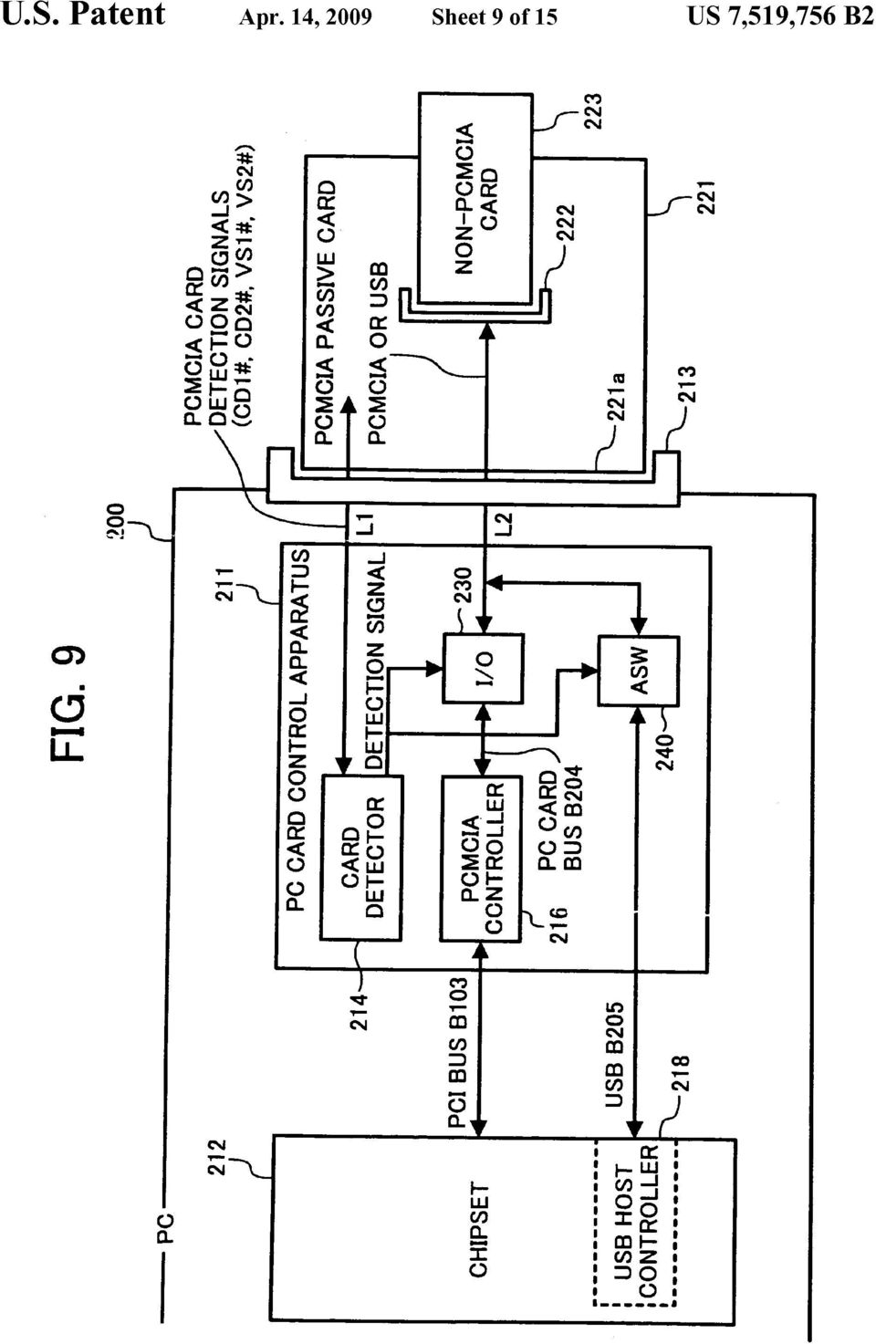
20 5 tor and an interconnection switching circuit. The PC card connector is con?gured to provide connections for connect ing one of a?rst PC card compliant with speci?c card stan dards and a second PC card compliant with a different card standard to the PC card control apparatus. The card detector is con?gured to detect insertion of the second PC card in the PC card control apparatus and to subsequently output a detection signal. The interconnection switching circuit is con?gured to switch the connections of the PC card connector to connect the PC card connector to a bus interface dedicated to the second PC card upon receiving the detection signal from the card detector. This patent speci?cation also describes, in one embodi ment, a novel method of controlling connections of?rst and second PC cards includes the steps of providing a PC card connector having connections for connecting one of a?rst PC card compliant with speci?c card standards and a second PC card compliant with a different card standard to a PC card control apparatus, detecting connection of the second PC card to the PC card control apparatus, outputting a detection signal upon a time the detecting step detects the insertion of the second PC card, and switching the connections of the PC card connector to connect the PC card connector to a bus interface dedicated to the second PC card upon receiving the detection signal output by the outputting step. Further, in one embodiment, a novel passive-card-adapting card includes a?rst card connector, a second card connector and a regulator. The?rst card connector is con?gured to be compatible with speci?c card standards for a?rst PC card and to connect the passive-card-adapting card to a PC card control apparatus. The second card connector is con?gured to have a connection for connecting a second PC card compliant with a card standard different from the speci?c card standards for the?rst PC card. The regulator is con?gured to regulate a power supply voltage supplied by the PC card control apparatus in order to adapt the power supply voltage for the second PC card. This patent speci?cation also describes, in one embodi ment, a novel method of controlling a passive-card-adapting card includes the steps of providing a connection for connect ing the passive-card-adapting card to a PC card control appa ratus, the passive-card-adapting card being compatible with speci?c card standards for a?rst PC card, regulating a power supply voltage supplied by the PC card control apparatus in order to adapt the power supply voltage for a second PC card compliant with a card standard different from the speci?c card standards for the?rst PC card, and providing a connec tion for connecting the second PC card. BRIEF DESCRIPTION OF THE DRAWINGS A more complete appreciation of the disclosure and many of the attendant advantages thereof will be readily obtained as the same becomes better understood by reference to the fol lowing detailed description when considered in connection with the accompanying drawings, wherein: FIG. 1 is an illustration showing a structure of a computer system including a conventional PC card control apparatus; FIG. 2 is an illustration showing a structure of a computer system including a PC card control apparatus of an exemplary embodiment according to the present patent speci?cation; FIG. 3 is an illustration showing a structure of an I/ O circuit provided in the PC card control apparatus of FIG. 2; FIG. 4 is an illustration showing a structure of an analog switch provided in the PC card control apparatus of FIG. 2; FIGS. 5A and 5B are illustrations of a detailed structure of the PC card control apparatus of FIG. 2; US 7,519,756 B FIG. 6 is a timing chart of signals issued in a PCMCIA passive-card-adapting card; FIG. 7 is a?owchart of card recognition operations per formed by the PC card control apparatus of the exemplary embodiment; FIG. 8 is a?owchart of card recognition operations per formed by a host computer of the exemplary embodiment; FIG. 9 is an illustration showing a structure of another computer system including a PC card control apparatus of another exemplary embodiment according to the present patent speci?cation; FIGS. 10A and 10B are illustrations of a detailed structure of the PC card control apparatus of FIG. 9 according to another exemplary embodiment of the present patent speci?cation; FIG. 11 is a?owchart of card recognition operations per formed by the PC card control apparatus of the exemplary embodiment; FIG. 12 is an illustration of a structure of another computer system including a PC card control apparatus of another exemplary embodiment according to the present patent speci?cation; FIG. 13 is an illustration of a structure of another computer system including a PC card control apparatus of another exemplary embodiment according to the present patent speci?cation; and FIG. 14 is an illustration of a structure of another computer system including a PC card control apparatus of another exemplary embodiment according to the present patent speci?cation. DETAILED DESCRIPTION OF THE PREFERRED EMBODIMENTS In describing preferred embodiments illustrated in the drawings, speci?c terminology is employed for the sake of clarity. However, the disclosure of this patent speci?cation is not intended to be limited to the speci?c terminology so selected and it is to be understood that each speci?c element includes all technical equivalents that operate in a similar manner. Referring now to the drawings, wherein like reference numerals designate identical or corresponding parts through out the several views, and particularly to FIG. 2, a structure of a computer system 100 is described according to an exem plary embodiment of the present patent speci?cation. As shown in FIG. 2, the computer system 100 includes a PC card control apparatus 111 and a chipset 112 connected to each other. The PC card control apparatus 111 is, for example, an extension board having a PC card connector 113 and includes a PC card detector 114, an I/O circuit 130 and an analog switch ( ASW in FIG. 2) 140. The chipset 112 is, for example, mounted on a mother board having a socket (not shown) for the extension board supporting a PCI bus B103 and a USB B105 used for the PC card control apparatus 111, and supports a CPU (not shown), a memory (not shown) and a USB host controller 118. The PC card control apparatus 111 may be integrated into a one-chip IC (integrated circuit) so that the PC card control apparatus 111 can be downsized. In addition, the PC card control apparatus 111 integrated into the one-chip IC can be connected to the chipset 112 through a small socket for IC. This allows the limited number of extension board sockets to be ef?ciently used. The PC card control apparatus 111 communicates with a PCMCIA passive-card-adapting card 121 through four con

21
22
23
24
25
\ \ \ connection connection connection interface interface interface
 US 20140122910A1 (19) United States (12) Patent Application Publication (10) Pub. No.: US 20140122910 A1 Chiu et al. (43) Pub. Date: May 1, 2014 (54) RACK SERVER SYSTEM AND OPERATION Publication Classi?cation
US 20070139188A1 (19) United States (12) Patent Application Publication (10) Pub. No.: US 2007/0139188 A1 Ollis et al. HOME PROCESSOR /\ J\ NETWORK
 United States (12) Patent Application Publication (10) Pub. No.: US 2007/0139188 A1 Ollis et al. HOME PROCESSOR /\ J\ NETWORK") US 20070139188A1 (19) United States (12) Patent Application Publication (10) Pub. No.: US 2007/0139188 A1 Ollis et al. (43) Pub. Date: Jun. 21, 2007 (54) (75) (73) (21) (22) METHOD AND APPARATUS FOR COMMUNICATING
US 20070139188A1 (19) United States (12) Patent Application Publication (10) Pub. No.: US 2007/0139188 A1 Ollis et al. (43) Pub. Date: Jun. 21, 2007 (54) (75) (73) (21) (22) METHOD AND APPARATUS FOR COMMUNICATING
(12) Patent Application Publication (10) Pub. No.: US 2003/0035525 A1 Wu et al. (43) Pub. Date: Feb. 20, 2003
 Patent Application Publication (10) Pub. No.: US 2003/0035525 A1 Wu et al. (43) Pub. Date: Feb. 20, 2003") (19) United States US 20030035525A1 (12) Patent Application Publication (10) Pub. No.: US 2003/0035525 A1 Wu et al. (43) Pub. Date: (54) (76) (21) (22) SYSTEM AND METHOD FOR DISTINGUISHING TELEPHONE NUMBER
(19) United States US 20030035525A1 (12) Patent Application Publication (10) Pub. No.: US 2003/0035525 A1 Wu et al. (43) Pub. Date: (54) (76) (21) (22) SYSTEM AND METHOD FOR DISTINGUISHING TELEPHONE NUMBER
US 20070016324A1 (19) United States (12) Patent Application Publication (10) Pub. No.: US 2007/0016324 A1. Operating System. 106 q f 108.
 United States (12) Patent Application Publication (10) Pub. No.: US 2007/0016324 A1. Operating System. 106 q f 108.") US 20070016324A1 (19) United States (12) Patent Application Publication (10) Pub. No.: US 2007/0016324 A1 Oddiraj u et al. (43) Pub. Date: Jan. 18, 2007 (54) SYSTEM BOOT OPTMZER (75) nventors: Chandar
US 20070016324A1 (19) United States (12) Patent Application Publication (10) Pub. No.: US 2007/0016324 A1 Oddiraj u et al. (43) Pub. Date: Jan. 18, 2007 (54) SYSTEM BOOT OPTMZER (75) nventors: Chandar
US 20130138449A1 (19) United States (12) Patent Application Publication (10) Pub. N0.: US 2013/0138449 A1 Pi0t (43) Pub. Date: May 30, 2013
 United States (12) Patent Application Publication (10) Pub. N0.: US 2013/0138449 A1 Pi0t (43) Pub. Date: May 30, 2013") US 20130138449A1 (19) United States (12) Patent Application Publication (10) Pub. N0.: US 2013/0138449 A1 Pi0t (43) Pub. Date: May 30, 2013 (54) SYSTEM AND METHOD FOR SCHEDULING (52) us. c1. HoME VISITS
US 20130138449A1 (19) United States (12) Patent Application Publication (10) Pub. N0.: US 2013/0138449 A1 Pi0t (43) Pub. Date: May 30, 2013 (54) SYSTEM AND METHOD FOR SCHEDULING (52) us. c1. HoME VISITS
(12) United States Patent (16) Patent N6.= US 6,198,814 B1 Gill (45) Date of Patent: Mar. 6, 2001
 United States Patent (16) Patent N6.= US 6,198,814 B1 Gill (45) Date of Patent: Mar. 6, 2001") US006198814B1 (12) United States Patent (16) Patent N6.= Gill (45) Date of Patent: Mar. 6, 2001 (54) SYSTEM AND METHOD FOR ENTERING 5,621,790 * 4/1997 Grossman 6161...... 379/266 CALL OUTCOME RECORDS IN
US006198814B1 (12) United States Patent (16) Patent N6.= Gill (45) Date of Patent: Mar. 6, 2001 (54) SYSTEM AND METHOD FOR ENTERING 5,621,790 * 4/1997 Grossman 6161...... 379/266 CALL OUTCOME RECORDS IN
(12) United States Patent Edelen
 United States Patent Edelen") US008285799B2 (12) United States Patent Edelen (10) Patent N0.: (45) Date of Patent: Oct. 9, 2012 (54) QUOTA-BASED ARCHIVING (75) Inventor: James Edelen, Renton, WA (U S) (73) Assignee: Microsoft Corporation,
US008285799B2 (12) United States Patent Edelen (10) Patent N0.: (45) Date of Patent: Oct. 9, 2012 (54) QUOTA-BASED ARCHIVING (75) Inventor: James Edelen, Renton, WA (U S) (73) Assignee: Microsoft Corporation,
(12) United States Patent (10) Patent N0.: US 7,068,424 B1 Jennings et al. (45) Date of Patent: Jun. 27, 2006
 United States Patent (10) Patent N0.: US 7,068,424 B1 Jennings et al. (45) Date of Patent: Jun. 27, 2006") US007068424B1 (12) United States Patent (10) Patent N0.: US 7,068,424 B1 Jennings et al. (45) Date of Patent: Jun. 27, 2006 (54) MULTIPLE PULSE GENERATION 6,141,127 A * 10/2000 Boivin et a1...... 398/92
US007068424B1 (12) United States Patent (10) Patent N0.: US 7,068,424 B1 Jennings et al. (45) Date of Patent: Jun. 27, 2006 (54) MULTIPLE PULSE GENERATION 6,141,127 A * 10/2000 Boivin et a1...... 398/92
llllllllllllllillllllllllllllllllllllllllllllllllllllllllllllllllllllllllll
 llllllllllllllillllllllllllllllllllllllllllllllllllllllllllllllllllllllllll USOO5535162A United States Patent [19] [11] Patent Number: 5,535,162 Uenoyama [45] Date of Patent: Jul. 9, 1996 [54] ELECTRICALLY
US 201203 03424Al (19) United States (12) Patent Application Publication (10) Pub. N0.: US 2012/0303424 A1 Lundstrom (43) Pub. Date: NOV.
 United States (12) Patent Application Publication (10) Pub. N0.: US 2012/0303424 A1 Lundstrom (43) Pub. Date: NOV.") US 201203 03424Al (19) United States (12) Patent Application Publication (10) Pub. N0.: US 2012/0303424 A1 Lundstrom (43) Pub. Date: NOV. 29, 2012 (54) METHOD AND SOFTWARE FOR Publication Classi?cation
US 201203 03424Al (19) United States (12) Patent Application Publication (10) Pub. N0.: US 2012/0303424 A1 Lundstrom (43) Pub. Date: NOV. 29, 2012 (54) METHOD AND SOFTWARE FOR Publication Classi?cation
US 20140046812A1 (19) United States (12) Patent Application Publication (10) Pub. No.: US 2014/0046812 A1 FAN et al. (43) Pub. Date: Feb.
 United States (12) Patent Application Publication (10) Pub. No.: US 2014/0046812 A1 FAN et al. (43) Pub. Date: Feb.") US 20140046812A1 (19) United States (12) Patent Application Publication (10) Pub. No.: US 2014/0046812 A1 FAN et al. (43) Pub. Date: (54) EXPENSE REPORTS FOR PAYMENTS MADE (52) US. Cl. WITH A MOBILE DEVICE
US 20140046812A1 (19) United States (12) Patent Application Publication (10) Pub. No.: US 2014/0046812 A1 FAN et al. (43) Pub. Date: (54) EXPENSE REPORTS FOR PAYMENTS MADE (52) US. Cl. WITH A MOBILE DEVICE
(12) United States Patent
 United States Patent") US008914855B2 (12) United States Patent Whitmyer, Jr. (10) Patent N0.: (45) Date of Patent: US 8,914,855 B2 Dec. 16, 2014 (54) PORTABLE PASSWORD KEEPER WITH INTERNET STORAGE AND RESTORE (75) Inventor:
US008914855B2 (12) United States Patent Whitmyer, Jr. (10) Patent N0.: (45) Date of Patent: US 8,914,855 B2 Dec. 16, 2014 (54) PORTABLE PASSWORD KEEPER WITH INTERNET STORAGE AND RESTORE (75) Inventor:
(Us) (73) Assignee: Avaya Technology Corp. Je?' McElroy, Columbia, SC (US); (21) Appl. No.: 10/413,024. (22) Filed: Apr. 14, 2003 (57) ABSTRACT
 (73) Assignee: Avaya Technology Corp. Je?' McElroy, Columbia, SC (US); (21) Appl. No.: 10/413,024. (22) Filed: Apr. 14, 2003 (57) ABSTRACT") US 20040202300A1 (19) United States (12) Patent Application Publication (10) Pub. No.: US 2004/0202300 A1 Cooper et al. (43) Pub. Date: Oct. 14, 2004 (54) CALL HANDLING USING NON-SPEECH CUES VIA A PERSONAL
US 20040202300A1 (19) United States (12) Patent Application Publication (10) Pub. No.: US 2004/0202300 A1 Cooper et al. (43) Pub. Date: Oct. 14, 2004 (54) CALL HANDLING USING NON-SPEECH CUES VIA A PERSONAL
US 20070041365A1 (19) United States (12) Patent Application Publication (10) Pub. No.: US 2007/0041365 A1 Nej ah (43) Pub. Date: Feb.
 United States (12) Patent Application Publication (10) Pub. No.: US 2007/0041365 A1 Nej ah (43) Pub. Date: Feb.") US 20070041365A1 (19) United States (12) Patent Application Publication (10) Pub. No.: US 2007/0041365 A1 Nej ah (43) Pub. Date: Feb. 22, 2007 (54) EBAY AND GOOGLE VOIP TELEPHONE (75) Inventor: Allen Nejah,
US 20070041365A1 (19) United States (12) Patent Application Publication (10) Pub. No.: US 2007/0041365 A1 Nej ah (43) Pub. Date: Feb. 22, 2007 (54) EBAY AND GOOGLE VOIP TELEPHONE (75) Inventor: Allen Nejah,
US 20090157756Al (19) United States (12) Patent Application Publication (10) Pub. No.: US 2009/0157756 A1 Sanvido (43) Pub. Date: Jun.
 United States (12) Patent Application Publication (10) Pub. No.: US 2009/0157756 A1 Sanvido (43) Pub. Date: Jun.") US 20090157756Al (19) United States (12) Patent Application Publication (10) Pub. No.: US 2009/0157756 A1 Sanvido (43) Pub. Date: Jun. 18, 2009 (54) FILE SYSTEM FOR STORING FILES IN Publication Classi?cation
US 20090157756Al (19) United States (12) Patent Application Publication (10) Pub. No.: US 2009/0157756 A1 Sanvido (43) Pub. Date: Jun. 18, 2009 (54) FILE SYSTEM FOR STORING FILES IN Publication Classi?cation
205 Controller / 205
 US 20130089195A1 (19) United States (12) Patent Application Publication (10) Pub. N0.: US 2013/0089195 A1 KIMBLE (43) Pub. Date: Apr. 1 1, 2013 (54) NEXT GENERATION AUTO-DIALER (52) US. Cl. CPC..... H04M3/42
US 20020072350A1 (19) United States (12) Patent Application Publication (10) Pub. No.: US 2002/0072350 A1 Fukuzato (43) Pub. Date: Jun.
 United States (12) Patent Application Publication (10) Pub. No.: US 2002/0072350 A1 Fukuzato (43) Pub. Date: Jun.") US 20020072350A1 (19) United States (12) Patent Application Publication (10) Pub. No.: US 20020072350 A1 Fukuzato (43) Pub. Date: Jun. 13, 2002 (54) BACKUP METHOD OF APPLICATIONS OF PORTABLE CELLULAR PHONE
US 20020072350A1 (19) United States (12) Patent Application Publication (10) Pub. No.: US 20020072350 A1 Fukuzato (43) Pub. Date: Jun. 13, 2002 (54) BACKUP METHOD OF APPLICATIONS OF PORTABLE CELLULAR PHONE
US 20050027827A1 (19) United States (12) Patent Application Publication (10) Pub. No.: US 2005/0027827 A1 Owhadi et al. (43) Pub. Date: Feb.
 United States (12) Patent Application Publication (10) Pub. No.: US 2005/0027827 A1 Owhadi et al. (43) Pub. Date: Feb.") US 20050027827A1 (19) United States (12) Patent Application Publication (10) Pub. No.: US 2005/0027827 A1 Owhadi et al. (43) Pub. Date: Feb. 3, 2005 (54) SYSTEM FOR PROVIDING SUPPORT FOR AN ELECTRONIC
US 20050027827A1 (19) United States (12) Patent Application Publication (10) Pub. No.: US 2005/0027827 A1 Owhadi et al. (43) Pub. Date: Feb. 3, 2005 (54) SYSTEM FOR PROVIDING SUPPORT FOR AN ELECTRONIC
(12) United States Patent (10) Patent N0.: US 8,695,377 B2 Bachelier et a]. (45) Date of Patent: Apr. 15, 2014
![(12) United States Patent (10) Patent N0.: US 8,695,377 B2 Bachelier et a]. (45) Date of Patent: Apr. 15, 2014](/thumbs/40/20550530.jpg "(12) United States Patent (10) Patent N0.: US 8,695,377 B2 Bachelier et a]. (45) Date of Patent: Apr. 15, 2014") USOO8695377B2 (12) United States Patent (10) Patent N0.: Bachelier et a]. (45) Date of Patent: Apr. 15, 2014 (54) PROCESS AND APPARATUS FOR THE (52) us. Cl. SEPARATION OF AIR BY CRYOGENIC USPC..... 62/644;
USOO8695377B2 (12) United States Patent (10) Patent N0.: Bachelier et a]. (45) Date of Patent: Apr. 15, 2014 (54) PROCESS AND APPARATUS FOR THE (52) us. Cl. SEPARATION OF AIR BY CRYOGENIC USPC..... 62/644;
(12) Patent Application Publication (10) Pub. No.: US 2013/0325512 A1 Kim et al. (43) Pub. Date: Dec. 5, 2013
 Patent Application Publication (10) Pub. No.: US 2013/0325512 A1 Kim et al. (43) Pub. Date: Dec. 5, 2013") (19) United States US 20130325512Al (12) Patent Application Publication (10) Pub. No.: US 2013/0325512 A1 Kim et al. (43) Pub. Date: Dec. 5, 2013 (54) ELECTRONIC MEDICAL RECORD SYSTEM Publication Classi?cation
(19) United States US 20130325512Al (12) Patent Application Publication (10) Pub. No.: US 2013/0325512 A1 Kim et al. (43) Pub. Date: Dec. 5, 2013 (54) ELECTRONIC MEDICAL RECORD SYSTEM Publication Classi?cation
: 2R5 ML OR 2. United States Patent [191. Fig-A3 [111 3,909,553. [451 Sept. 30, 1975 C54 ( T : Marshall. Laboratories Incorporated, Northlake, Ill.
 United States Patent [191 Marshall [111 3,909,553 [451 Sept. 30, 1975 I54] LINE CARD FOR KEY TELEPHONE SYSTEMS ADAPTED TO PROVIDE MUSIC DURING HOLD CONDITION [75] Inventor: Richard A. Marshall, Bensenville.
(12) Ulllted States Patent (10) Patent N0.: US 8,389,837 B1 Leguia (45) Date of Patent: Mar. 5, 2013
 Ulllted States Patent (10) Patent N0.: US 8,389,837 B1 Leguia (45) Date of Patent: Mar. 5, 2013") US008389837B1 (12) Ulllted States Patent (10) Patent N0.: US 8,389,837 B1 Leguia (45) Date of Patent: Mar. 5, 2013 (54) STRINGED INSTRUMENT HAVINGA 4,836,076 A 6/1989 Bernier FRETBOARD CANTILEVERED OVER
US008389837B1 (12) Ulllted States Patent (10) Patent N0.: US 8,389,837 B1 Leguia (45) Date of Patent: Mar. 5, 2013 (54) STRINGED INSTRUMENT HAVINGA 4,836,076 A 6/1989 Bernier FRETBOARD CANTILEVERED OVER
software, and perform automatic dialing according to the /*~102
 US 20140105199A1 (19) United States (12) Patent Application Publication (10) Pub. No.: US 2014/0105199 A1 Tian (43) Pub. Date: (54) METHOD AND APPARATUS FOR AUTOMATIC DIALING ACCESS POINTS (71) Applicant:
(54) LOTTERY METHOD Publication Classi?cation
 LOTTERY METHOD Publication Classi?cation") US 20130231987A1 (19) United States (12) Patent Application Publication (10) Pub. No.: US 2013/0231987 A1 Veverka et al. (43) Pub. Date: Sep. 5, 2013 (54) LOTTERY METHOD Publication Classi?cation (71)
US 20130231987A1 (19) United States (12) Patent Application Publication (10) Pub. No.: US 2013/0231987 A1 Veverka et al. (43) Pub. Date: Sep. 5, 2013 (54) LOTTERY METHOD Publication Classi?cation (71)
Ulllted States Patent [19] [11] Patent Number: 5,943,406
![Ulllted States Patent [19] [11] Patent Number: 5,943,406](/thumbs/30/14188909.jpg "Ulllted States Patent [19] [11] Patent Number: 5,943,406") US005943406A Ulllted States Patent [19] [11] Patent Number: 5,943,406 Leta et al. [45] Date of Patent: Aug. 24, 1999 [54] TELEPHONE CALL TRACKING AND 4,813,065 3/1989 Segala..... 379/112 BILLING SYSTEM
US005943406A Ulllted States Patent [19] [11] Patent Number: 5,943,406 Leta et al. [45] Date of Patent: Aug. 24, 1999 [54] TELEPHONE CALL TRACKING AND 4,813,065 3/1989 Segala..... 379/112 BILLING SYSTEM
Patent Application Publication Sep. 30, 2004 Sheet 1 0f 2. Hierarchical Query. Contact Ow FIG. 1
 US 20040193595A1 (19) United States (12) Patent Application Publication (10) Pub. No.: US 2004/0193595 A1 Kaminsky et al. (43) Pub. Date: Sep. 30, 2004 (54) NEAREST KNOWN PERSON DIRECTORY FUNCTION (75)
Hay (43) Pub. Date: Oct. 17, 2002
 Pub. Date: Oct. 17, 2002") US 20020152322A1 (19) United States (12) Patent Application Publication (10) Pub. No.: US 2002/0152322 A1 Hay (43) Pub. Date: Oct. 17, 2002 (54) (76) (21) (22) (51) (52) METHOD AND APPARATUS FOR FACILITATING
US 20020152322A1 (19) United States (12) Patent Application Publication (10) Pub. No.: US 2002/0152322 A1 Hay (43) Pub. Date: Oct. 17, 2002 (54) (76) (21) (22) (51) (52) METHOD AND APPARATUS FOR FACILITATING
60 REDIRECTING THE PRINT PATH MANAGER 1
 US006788429B1 (12) United States Patent (10) Patent No.: US 6,788,429 B1 Clough et al. (45) Date of Patent: Sep. 7, 2004 (54) REMOTE PRINT QUEUE MANAGEMENT FOREIGN PATENT DOCUMENTS (75) Inventors: James
(12) United States Patent Halonen
 United States Patent Halonen") (12) United States Patent Halonen US006334053B1 () Patent N0.: (45) Date of Patent: Dec. 25, 2001 (54) PROCEDURE AND SYSTEM FOR PROVIDING AN ANSWERING SERVICE (75) Inventor: Mikko Halonen, Oulu (Fl) (73)
(12) United States Patent Halonen US006334053B1 () Patent N0.: (45) Date of Patent: Dec. 25, 2001 (54) PROCEDURE AND SYSTEM FOR PROVIDING AN ANSWERING SERVICE (75) Inventor: Mikko Halonen, Oulu (Fl) (73)
US 20020116467A1 (19) United States (12) Patent Application Publication (10) Pub. No.: US 2002/0116467 A1 Boyer et al. (43) Pub. Date: Aug.
 United States (12) Patent Application Publication (10) Pub. No.: US 2002/0116467 A1 Boyer et al. (43) Pub. Date: Aug.") US 20020116467A1 (19) United States (12) Patent Application Publication (10) Pub. No.: US 2002/0116467 A1 Boyer et al. (43) Pub. Date: Aug. 22, 2002 (54) METHOD AND APPARATUS FOR Publication Classi?cation
US 20020116467A1 (19) United States (12) Patent Application Publication (10) Pub. No.: US 2002/0116467 A1 Boyer et al. (43) Pub. Date: Aug. 22, 2002 (54) METHOD AND APPARATUS FOR Publication Classi?cation
/ \33 40 \ / \\ \ \ M / 32. 28f 1. (19) United States (12) Patent Application Publication Lawser et al. NETWORK \ 36. SERVlCE 'NTERNET SERVICE
 United States (12) Patent Application Publication Lawser et al. NETWORK \ 36. SERVlCE 'NTERNET SERVICE") (19) United States (12) Patent Application Publication Lawser et al. US 20130336314A1 (10) Pub. N0.: US 2013/0336314 A1 (43) Pub. Date: Dec. 19, 2013 (54) (71) (72) (73) (21) (22) (63) METHOD FOR COMPLETING
(19) United States (12) Patent Application Publication Lawser et al. US 20130336314A1 (10) Pub. N0.: US 2013/0336314 A1 (43) Pub. Date: Dec. 19, 2013 (54) (71) (72) (73) (21) (22) (63) METHOD FOR COMPLETING
(12) United States Patent (10) Patent No.: US 8,253,226 B2 Oguri (45) Date of Patent: Aug. 28, 2012
 United States Patent (10) Patent No.: US 8,253,226 B2 Oguri (45) Date of Patent: Aug. 28, 2012") US008253226B2 (12) United States Patent (10) Patent No.: US 8,253,226 B2 Oguri (45) Date of Patent: Aug. 28, 2012 (54) ELECTRONIC PARTS, AND METHOD FOR (56) References Cited ARRANGING SHIELDING CASE AND
US008253226B2 (12) United States Patent (10) Patent No.: US 8,253,226 B2 Oguri (45) Date of Patent: Aug. 28, 2012 (54) ELECTRONIC PARTS, AND METHOD FOR (56) References Cited ARRANGING SHIELDING CASE AND
United States Patent [191
 United States Patent [191 Fancy [54] REDUNDANT SIGNAL CIRCUIT [75] Inventor: Thomas A. Fancy, Westminster, Mass. [73] Assignee: General Electric Company, Schenectady, NY. [211 Appl. No.: 854,973 [22] Filed:
(12) United States Patent (10) Patent N0.: US 8,282,471 B1 Korner (45) Date of Patent: Oct. 9, 2012
 United States Patent (10) Patent N0.: US 8,282,471 B1 Korner (45) Date of Patent: Oct. 9, 2012") US008282471B1 (12) United States Patent (10) Patent N0.: US 8,282,471 B1 Korner (45) Date of Patent: Oct. 9, 2012 (54) COMPUTER-IMPLEMENTED SPORTS 2011/0003634 A1* 1/2011 Manteris..... 463/25 WAGERING
US008282471B1 (12) United States Patent (10) Patent N0.: US 8,282,471 B1 Korner (45) Date of Patent: Oct. 9, 2012 (54) COMPUTER-IMPLEMENTED SPORTS 2011/0003634 A1* 1/2011 Manteris..... 463/25 WAGERING
MAIN COMPUTER MONlTOR. INPUT/ OUTPUT ClRCUlT. 4,748,566 May 31, 1988. United States Patent [191. [11] Patent Number: [45] Date of Patent:
![MAIN COMPUTER MONlTOR. INPUT/ OUTPUT ClRCUlT. 4,748,566 May 31, 1988. United States Patent [191. [11] Patent Number: [45] Date of Patent:](/thumbs/29/13384343.jpg "MAIN COMPUTER MONlTOR. INPUT/ OUTPUT ClRCUlT. 4,748,566 May 31, 1988. United States Patent [191. [11] Patent Number: [45] Date of Patent:") United States Patent [191 Sasaki et al. [11] Patent Number: [45] Date of Patent: May 31, 1988 [54] ENGINE CONTROL APPARATUS [75] Inventors: Shoji Sasaki; Kenji Tabuchi, both of Katsuta, Japan [73] Assignee:
United States Patent [191 Sasaki et al. [11] Patent Number: [45] Date of Patent: May 31, 1988 [54] ENGINE CONTROL APPARATUS [75] Inventors: Shoji Sasaki; Kenji Tabuchi, both of Katsuta, Japan [73] Assignee:
(12) United States Patent (10) Patent N0.: US 8,721,047 B2 Sakurai et a]. (45) Date of Patent: May 13, 2014
![(12) United States Patent (10) Patent N0.: US 8,721,047 B2 Sakurai et a]. (45) Date of Patent: May 13, 2014](/thumbs/39/20155291.jpg "(12) United States Patent (10) Patent N0.: US 8,721,047 B2 Sakurai et a]. (45) Date of Patent: May 13, 2014") USOO8721047B2 (12) United States Patent (10) Patent N0.: US 8,721,047 B2 Sakurai et a]. (45) Date of Patent: May 13, 2014 (54) LIQUID EJECTION HEAD AND INK JET (56) References Cited PRINTING APPARATUS
USOO8721047B2 (12) United States Patent (10) Patent N0.: US 8,721,047 B2 Sakurai et a]. (45) Date of Patent: May 13, 2014 (54) LIQUID EJECTION HEAD AND INK JET (56) References Cited PRINTING APPARATUS
(12) (10) Patent N0.: US 6,614,314 B2 d Haene et al. 45 Date 0f Patent: Se. 2 2003 (54) NON-LINEAR PHASE DETECTOR FOREIGN PATENT DOCUMENTS
 (10) Patent N0.: US 6,614,314 B2 d Haene et al. 45 Date 0f Patent: Se. 2 2003 (54) NON-LINEAR PHASE DETECTOR FOREIGN PATENT DOCUMENTS") United States Patent US006614314B2 (12) (10) Patent N0.: US 6,614,314 B2 d Haene et al. 45 Date 0f Patent: Se. 2 2003 a (54) NON-LINEAR PHASE DETECTOR FOREIGN PATENT DOCUMENTS (75) Inventors: Wesley Calvin
United States Patent US006614314B2 (12) (10) Patent N0.: US 6,614,314 B2 d Haene et al. 45 Date 0f Patent: Se. 2 2003 a (54) NON-LINEAR PHASE DETECTOR FOREIGN PATENT DOCUMENTS (75) Inventors: Wesley Calvin
51 7 522 Ml CRO- MICRO PLEASE
 US005951462A Ulllted States Patent [19] [11] Patent Number: 5,951,462 Yamanaka [45] Date of Patent: Sep. 14, 1999 [54] ELECTRONIC ENDOSCOPE SYSTEM FOR 5,402,769 4/1995 Tsuji..... 600/109 DISPLAYING UNCONNECTED
US006282278B1 (12) United States Patent. (10) Patent N0.: US 6,282,278 B1 D0ganata et al. (45) Date 0f Patent: Aug. 28, 2001
 United States Patent. (10) Patent N0.: US 6,282,278 B1 D0ganata et al. (45) Date 0f Patent: Aug. 28, 2001") US006282278B1 (12) United States Patent (10) Patent N0.: US 6,282,278 B1 D0ganata et al. (45) Date 0f Patent: Aug. 28, 2001 (54) UNIVERSAL CONFERENCE CONTROL 5,758,281 * 5/1998 Emery et a1...... 455/428
US006282278B1 (12) United States Patent (10) Patent N0.: US 6,282,278 B1 D0ganata et al. (45) Date 0f Patent: Aug. 28, 2001 (54) UNIVERSAL CONFERENCE CONTROL 5,758,281 * 5/1998 Emery et a1...... 455/428
(71) Applicant: SPEAKWRITE, LLC,Austin, TX (US)
 Applicant: SPEAKWRITE, LLC,Austin, TX (US)") US 20130304465Al (19) United States (12) Patent Application Publication (10) Pub. No.: US 2013/0304465 A1 Henry et al. (43) Pub. Date: NOV. 14, 2013 (54) METHOD AND SYSTEM FOR AUDIO-VIDEO (52) US. Cl.
US 20130304465Al (19) United States (12) Patent Application Publication (10) Pub. No.: US 2013/0304465 A1 Henry et al. (43) Pub. Date: NOV. 14, 2013 (54) METHOD AND SYSTEM FOR AUDIO-VIDEO (52) US. Cl.
(54) RAPID NOTIFICATION SYSTEM (52) US. Cl... 709/206. (57) ABSTRACT (75) Inventors: Anand Rajasekar, San Jose, CA
 RAPID NOTIFICATION SYSTEM (52) US. Cl... 709/206. (57) ABSTRACT (75) Inventors: Anand Rajasekar, San Jose, CA") US 20120303720A1 (19) United States (12) Patent Application Publication (10) Pub. N0.: US 2012/0303720 A1 Rajasekar et a]. (43) Pub. Date: NOV. 29, 2012 (54) RAPID NOTIFICATION SYSTEM (52) US. Cl......
US 20120303720A1 (19) United States (12) Patent Application Publication (10) Pub. N0.: US 2012/0303720 A1 Rajasekar et a]. (43) Pub. Date: NOV. 29, 2012 (54) RAPID NOTIFICATION SYSTEM (52) US. Cl......
Telephone Dressing Systems - Advantages and Disadvantages
 I US 20030185352A1 (19) United States (12) Patent Application Publication (10) Pub. No.: US 2003/0185352 A1 Savage et al. (43) Pub. Date: (54) AUTOMATED MESSAGE BROADCAST SYSTEM WITH DUAL MESSAGE SOURCES
(12> Ulllted States Patent (10) Patent N0.: US 6,591,288 B1 Edwards et al. (45) Date of Patent: Jul. 8, 2003
 Patent N0.: US 6,591,288 B1 Edwards et al. (45) Date of Patent: Jul. 8, 2003") ' ' US006591288B1 (12> Ulllted States Patent (10) Patent N0.: Edwards et al. (45) Date of Patent: Jul. 8, 2003 (54) DATA NETWORK ACCELERATED ACCESS EP 0837584 4/1998..... H04L/29/06 SYSTEM W0 WO 96/34340
' ' US006591288B1 (12> Ulllted States Patent (10) Patent N0.: Edwards et al. (45) Date of Patent: Jul. 8, 2003 (54) DATA NETWORK ACCELERATED ACCESS EP 0837584 4/1998..... H04L/29/06 SYSTEM W0 WO 96/34340
US 20070019798Al (19) United States (12) Patent Application Publication (10) Pub. No.: US 2007/0019798 A1 Voight et al. SUBSCRIBER DATABASE.
 United States (12) Patent Application Publication (10) Pub. No.: US 2007/0019798 A1 Voight et al. SUBSCRIBER DATABASE.") US 20070019798Al (19) United States (12) Patent Application Publication (10) Pub. No.: US 2007/0019798 A1 Voight et al. (43) Pub. Date: Jan. 25, 2007 (54) METHOD AND APPARATUS FOR PROVIDING CUSTOMIZED
US 20070019798Al (19) United States (12) Patent Application Publication (10) Pub. No.: US 2007/0019798 A1 Voight et al. (43) Pub. Date: Jan. 25, 2007 (54) METHOD AND APPARATUS FOR PROVIDING CUSTOMIZED
Naylor, Lake OsWego, OR (US) (51) Int_ CL
 (51) Int_ CL") US 20100023688A1 (19) United States (12) Patent Application Publication (10) Pub. No.: US 2010/0023688 A1 Crowther et al. (43) Pub. Date: (54) SYMMETRICAL STORAGE ACCESS ON (86) PCT No.: PCT/US2007/001542
US 20100023688A1 (19) United States (12) Patent Application Publication (10) Pub. No.: US 2010/0023688 A1 Crowther et al. (43) Pub. Date: (54) SYMMETRICAL STORAGE ACCESS ON (86) PCT No.: PCT/US2007/001542
(12) United States Patent Armenio et a].
![(12) United States Patent Armenio et a].](/thumbs/40/20558097.jpg "(12) United States Patent Armenio et a].") US008425210B2 (12) United States Patent Armenio et a]. (10) Patent N0.: (45) Date of Patent: Apr. 23, 2013 (54) TWO-SETTINGVARIABLE-ECCENTRICITY VANE PUMP (75) Inventors: Giacomo Armenio, Livorno (IT);
US008425210B2 (12) United States Patent Armenio et a]. (10) Patent N0.: (45) Date of Patent: Apr. 23, 2013 (54) TWO-SETTINGVARIABLE-ECCENTRICITY VANE PUMP (75) Inventors: Giacomo Armenio, Livorno (IT);
US 20130073440A1 (19) United States (12) Patent Application Publication (10) Pub. No.: US 2013/0073440 A1 Chen (57)
 United States (12) Patent Application Publication (10) Pub. No.: US 2013/0073440 A1 Chen (57)") US 20130073440A1 (19) United States (12) Patent Application Publication (10) Pub. No.: US 2013/0073440 A1 Chen (43) Pub. Date: Mar. 21, 2013 (54) PAYROLL SYSTEM AND METHOD Publication Classi?cation (76)
US 20130073440A1 (19) United States (12) Patent Application Publication (10) Pub. No.: US 2013/0073440 A1 Chen (43) Pub. Date: Mar. 21, 2013 (54) PAYROLL SYSTEM AND METHOD Publication Classi?cation (76)
222252 211222 1111;111:131... ~~~~~~~~~~~~~~~~~~~ 2221522 [73] Assigneez Rockwell Semiconductor Systems 5,754,639 5/1998 Flockhart et al...
![222252 211222 1111;111:131... ~~~~~~~~~~~~~~~~~~~ 2221522 [73] Assigneez Rockwell Semiconductor Systems 5,754,639 5/1998 Flockhart et al...](/thumbs/31/14952948.jpg "222252 211222 1111;111:131... ~~~~~~~~~~~~~~~~~~~ 2221522 [73] Assigneez Rockwell Semiconductor Systems 5,754,639 5/1998 Flockhart et al...") I I US0059012A Ulllted States Patent [19] [11] Patent Number: Dez0nn0 [] Date of Patent: * May 4, 1999 [54] APPARATUS AND METHOD FOR 5,526,416 6/1996 DeZonno et al...... 379/266 IDENTIFYING RECORDS ()1?
I I US0059012A Ulllted States Patent [19] [11] Patent Number: Dez0nn0 [] Date of Patent: * May 4, 1999 [54] APPARATUS AND METHOD FOR 5,526,416 6/1996 DeZonno et al...... 379/266 IDENTIFYING RECORDS ()1?
US 20110043191A1 (19) United States (12) Patent Application Publication (10) Pub. No.: US 2011/0043191 A1 Gutierrez (43) Pub. Date: Feb.
 United States (12) Patent Application Publication (10) Pub. No.: US 2011/0043191 A1 Gutierrez (43) Pub. Date: Feb.") US 20110043191A1 (19) United States (12) Patent Application Publication (10) Pub. No.: US 2011/0043191 A1 Gutierrez (43) Pub. Date: Feb. 24, 2011 (54) PHOENIX PROBE X VOLTAGE TESTER Publication Classi?cation
US 20110043191A1 (19) United States (12) Patent Application Publication (10) Pub. No.: US 2011/0043191 A1 Gutierrez (43) Pub. Date: Feb. 24, 2011 (54) PHOENIX PROBE X VOLTAGE TESTER Publication Classi?cation
(12> Ulllted States Patent (16) Patent N6.= US 6,320,621 B1 Fu (45) Date of Patent: Nov. 20, 2001
 Patent N6.= US 6,320,621 B1 Fu (45) Date of Patent: Nov. 20, 2001") US006320621B1 (12> Ulllted States Patent (16) Patent N6.= Fu (45) Date of Patent: Nov. 20, 2001 (54) METHOD OF SELECTINGADIGITAL 5,818,935 * 10/1998 Maa..... 380/20 ING SERVICE 5.900.908 * 5/1999 Kirkland
US006320621B1 (12> Ulllted States Patent (16) Patent N6.= Fu (45) Date of Patent: Nov. 20, 2001 (54) METHOD OF SELECTINGADIGITAL 5,818,935 * 10/1998 Maa..... 380/20 ING SERVICE 5.900.908 * 5/1999 Kirkland
(12) United States Patent (16) Patent N6.= US 6,611,861 B1 Schairer et al. (45) Date of Patent: Aug. 26, 2003
 United States Patent (16) Patent N6.= US 6,611,861 B1 Schairer et al. (45) Date of Patent: Aug. 26, 2003") US006611861B1 (12) United States Patent (16) Patent N6.= Schairer et al. () Date of Patent: Aug. 26, 2003 (54) INTERNET HOSTING AND ACCESS SYSTEM Primary Examiner AyaZ Sheikh AND METHOD Assistant Examiner
US006611861B1 (12) United States Patent (16) Patent N6.= Schairer et al. () Date of Patent: Aug. 26, 2003 (54) INTERNET HOSTING AND ACCESS SYSTEM Primary Examiner AyaZ Sheikh AND METHOD Assistant Examiner
(12) United States Patent (10) Patent No.: US 8,349,484 B2 Do et a]. (45) Date of Patent: Jan. 8, 2013
![(12) United States Patent (10) Patent No.: US 8,349,484 B2 Do et a]. (45) Date of Patent: Jan. 8, 2013](/thumbs/40/20543675.jpg "(12) United States Patent (10) Patent No.: US 8,349,484 B2 Do et a]. (45) Date of Patent: Jan. 8, 2013") US008349484B2 (12) United States Patent (10) Patent No.: US 8,349,484 B2 Do et a]. (45) Date of Patent: Jan. 8, 2013 (54) STACKING METHOD OF HIGH POWER 2007/0072083 A1 * 3/2007 Ikuta et al...... 429/246
US008349484B2 (12) United States Patent (10) Patent No.: US 8,349,484 B2 Do et a]. (45) Date of Patent: Jan. 8, 2013 (54) STACKING METHOD OF HIGH POWER 2007/0072083 A1 * 3/2007 Ikuta et al...... 429/246
Ulllted States Patent [19] [11] Patent Number: 6,141,545
![Ulllted States Patent [19] [11] Patent Number: 6,141,545](/thumbs/27/11642488.jpg "Ulllted States Patent [19] [11] Patent Number: 6,141,545") US0061445A Ulllted States Patent [19] [11] Patent Number: Begeja et al. [45] Date of Patent: *Oct. 31, 2000 [54] METHOD AND SYSTEM FOR REMOTE 5,440,614 8/1995 Sonberg et a1...... 455/414 CALL FORWARDING
US0061445A Ulllted States Patent [19] [11] Patent Number: Begeja et al. [45] Date of Patent: *Oct. 31, 2000 [54] METHOD AND SYSTEM FOR REMOTE 5,440,614 8/1995 Sonberg et a1...... 455/414 CALL FORWARDING
(12) United States Patent Mine et al.
 United States Patent Mine et al.") US008612715B2 (12) United States Patent Mine et al. (10) Patent N0.: (45) Date of Patent: US 8,612,715 B2 *Dec. 17, 2013 (54) (75) (73) (21) (22) (65) (63) (51) (52) (58) STORAGE SYSTEM AND UTILIZATION
US008612715B2 (12) United States Patent Mine et al. (10) Patent N0.: (45) Date of Patent: US 8,612,715 B2 *Dec. 17, 2013 (54) (75) (73) (21) (22) (65) (63) (51) (52) (58) STORAGE SYSTEM AND UTILIZATION
US 20020128882A1 (19) United States (12) Patent Application Publication (10) Pub. N0.: US 2002/0128882 A1
 United States (12) Patent Application Publication (10) Pub. N0.: US 2002/0128882 A1") US 20020128882A1 (19) United States (12) Patent Application Publication (10) Pub. N0.: US 2002/0128882 A1 Nakagawa et al. (43) Pub. Date: Sep. 12, 2002 (54) VEHICLE INSURANCE PREMIUM (22) Filed: Feb. 27,
US 20020128882A1 (19) United States (12) Patent Application Publication (10) Pub. N0.: US 2002/0128882 A1 Nakagawa et al. (43) Pub. Date: Sep. 12, 2002 (54) VEHICLE INSURANCE PREMIUM (22) Filed: Feb. 27,
etc.) (ERP) Computer System (e.g., columns, rows,?elds, r16 (e.g., Database) 24 Enterprise Resource Planning Table Objects Module 0 r26
 (ERP) Computer System (e.g., columns, rows,?elds, r16 (e.g., Database) 24 Enterprise Resource Planning Table Objects Module 0 r26") US 20120221582A1 (19) United States (12) Patent Application Publication (10) Pub. No.: US 2012/0221582 A1 Boross et al. (43) Pub. Date: Aug. 30, 2012 (54) SETTING AND DISPLAYING PRIMARY (52) US. Cl......
US 20120221582A1 (19) United States (12) Patent Application Publication (10) Pub. No.: US 2012/0221582 A1 Boross et al. (43) Pub. Date: Aug. 30, 2012 (54) SETTING AND DISPLAYING PRIMARY (52) US. Cl......
US 20120215907A1 (19) United States (12) Patent Application Publication (10) Pub. No.: US 2012/0215907 A1 Chung (43) Pub. Date: Aug.
 United States (12) Patent Application Publication (10) Pub. No.: US 2012/0215907 A1 Chung (43) Pub. Date: Aug.") US 20120215907A1 (19) United States (12) Patent Application Publication (10) Pub. No.: US 2012/0215907 A1 Chung (43) Pub. Date: (54) SYSTEMS AND METHODS FOR (52) US. Cl...... 709/224 SELF-ADJUSTING LOGGING
US 20120215907A1 (19) United States (12) Patent Application Publication (10) Pub. No.: US 2012/0215907 A1 Chung (43) Pub. Date: (54) SYSTEMS AND METHODS FOR (52) US. Cl...... 709/224 SELF-ADJUSTING LOGGING
17 Claims, 19 Drawing Sheets EG4 SD4 {8L4 ( I; DLI Q P A. \! v,zcll. RG1 7 / l. a U ' 14 A I 1) ~ $133 .. _. _. _. T. _. _. _. /,.
 ~ $133 .. _. _. _. T. _. _. _. /,.") US008564751B2 (12) United States Patent Nakanishi et a]. (10) Patent N0.: (45) Date of Patent: US 8,564,751 B2 Oct. 22, 2013 (54) (75) (73) ( * ) (21) (22) (86) (87) (65) (30) Apr. 17, 2009 (JP)..... 2009-101273
US008564751B2 (12) United States Patent Nakanishi et a]. (10) Patent N0.: (45) Date of Patent: US 8,564,751 B2 Oct. 22, 2013 (54) (75) (73) ( * ) (21) (22) (86) (87) (65) (30) Apr. 17, 2009 (JP)..... 2009-101273
(54) METHODS AND SYSTEMS FOR FINDING Publication Classi?cation CONNECTIONS AMONG SUBSCRIBERS TO AN EMAIL CAMPAIGN (51) Int- Cl
 METHODS AND SYSTEMS FOR FINDING Publication Classi?cation CONNECTIONS AMONG SUBSCRIBERS TO AN EMAIL CAMPAIGN (51) Int- Cl") US 201403 79420A1 (19) United States (12) Patent Application Publication (10) Pub. No.: US 2014/0379420 A1 Chestnut et al. (43) Pub. Date: Dec. 25, 2014 (54) METHODS AND SYSTEMS FOR FINDING Publication
US 201403 79420A1 (19) United States (12) Patent Application Publication (10) Pub. No.: US 2014/0379420 A1 Chestnut et al. (43) Pub. Date: Dec. 25, 2014 (54) METHODS AND SYSTEMS FOR FINDING Publication
US006424627B1 (12) United States Patent. (10) Patent N0.: US 6,424,627 B1 Snrhaug et al. (45) Date of Patent: Jul. 23, 2002
 United States Patent. (10) Patent N0.: US 6,424,627 B1 Snrhaug et al. (45) Date of Patent: Jul. 23, 2002") US006424627B1 (12) United States Patent (10) Patent N0.: Snrhaug et al. (45) Date of Patent: Jul. 23, 2002 (54) FULL-DUPLEX MEDIUM TAPAPPARATUS 5,459,723 A 10/1995 Thor AND SYSTEM 5,923,654 A * 7/1999
US006424627B1 (12) United States Patent (10) Patent N0.: Snrhaug et al. (45) Date of Patent: Jul. 23, 2002 (54) FULL-DUPLEX MEDIUM TAPAPPARATUS 5,459,723 A 10/1995 Thor AND SYSTEM 5,923,654 A * 7/1999
US 20130254326Al (19) United States (12) Patent Application Publication (10) Pub. No.: US 2013/0254326 A1 Weng et al. (43) Pub. Date: Sep.
 United States (12) Patent Application Publication (10) Pub. No.: US 2013/0254326 A1 Weng et al. (43) Pub. Date: Sep.") 1 l US 20130254326Al (19) United States (12) Patent Application Publication (10) Pub. No.: US 2013/0254326 A1 Weng et al. (43) Pub. Date: Sep. 26, 2013 (54) ELECTRONIC DEVICE, CLOUD STORAGE Publication
1 l US 20130254326Al (19) United States (12) Patent Application Publication (10) Pub. No.: US 2013/0254326 A1 Weng et al. (43) Pub. Date: Sep. 26, 2013 (54) ELECTRONIC DEVICE, CLOUD STORAGE Publication
* cited by examiner. f130 CPU. r1204 I /110 r140. Endpoint Host Brldge Memory. /120-2 I 150 f120-3 Endpoint SW'tCh Endpoint. F1204 r120-5 f120-n
 US008374157B2 (12) United States Patent Tamir et a1. (10) Patent N0.: (45) Date of Patent: Feb. 12, 2013 (54) (75) (73) (*) (21) (22) (65) (60) (51) (52) (58) WIRELESS DOCKING STATION Inventors: Tal Tamir,
Back up information data by blocks, and generate backup data of each block
 US 20140046903A1 (19) United States (12) Patent Application Publication (10) Pub. No.: US 2014/0046903 A1 Ylll (43) Pub. Date: (54) DATA BACKUP AND RECOVERY METHOD Publication Classi?cation FOR MOBILE
United States Patent [191 [11] Patent Number: 4,779,221 Magliocco et al. [45] Date of Patent: Oct. 18, 1988
![United States Patent [191 [11] Patent Number: 4,779,221 Magliocco et al. [45] Date of Patent: Oct. 18, 1988](/thumbs/24/4204589.jpg "United States Patent [191 [11] Patent Number: 4,779,221 Magliocco et al. [45] Date of Patent: Oct. 18, 1988") United States Patent [191 [11] Patent Number: 4,779,221 Magliocco et al. [45] Date of Patent: Oct. 18, 1988 [54] TIMING SIGNAL GENERATOR 4,063,308 12/1977 Collins et a1...... 364/900 4,231,104 10/1980
United States Patent [191 [11] Patent Number: 4,779,221 Magliocco et al. [45] Date of Patent: Oct. 18, 1988 [54] TIMING SIGNAL GENERATOR 4,063,308 12/1977 Collins et a1...... 364/900 4,231,104 10/1980
3,2 74,344 AUTOMATIC DIALING DEVICE. Filed June 14, 1963. 5 Sheets-Sheet 1 24 \ l NVENTOR. CHARLES C. YOUNG / /////% B73744 2?
 Sept. 20, 1966 Filed June 14, 1963 c. c. YOUNG AUTOMATIC DIALING DEVICE 3,2 74,344 5 Sheets-Sheet 1 3 w. L? U; / m wk, m 5 V/Wh :: ///////,// F G 2 w 24 \ / /////% 2-4 l NVENTOR. CHARLES C. YOUNG B73744
4,670,900 Jun. 2, 1987
 United States Patent [19] Waldman [11] Patent Number: [45] Date of Patent: 4,670,900 Jun. 2, 1987 [54] SINGLE LINE TELEPHONE CALL FORWARDING DEVICE [76] Inventor: Herbert H. Waldman, 1739 52nd St., Brooklyn,
US 20130325834A1 (19) United States (12) Patent Application Publication (10) Pub. N0.: US 2013/0325834 A1 Simburg (43) Pub. Date: Dec.
 United States (12) Patent Application Publication (10) Pub. N0.: US 2013/0325834 A1 Simburg (43) Pub. Date: Dec.") US 20130325834A1 (19) United States (12) Patent Application Publication (10) Pub. N0.: US 2013/0325834 A1 Simburg (43) Pub. Date: Dec. 5, 2013 (54) LINK ALLOCATION FOR SEARCH ENGINE (52) US. Cl. OPTIMIZATION
US 20130325834A1 (19) United States (12) Patent Application Publication (10) Pub. N0.: US 2013/0325834 A1 Simburg (43) Pub. Date: Dec. 5, 2013 (54) LINK ALLOCATION FOR SEARCH ENGINE (52) US. Cl. OPTIMIZATION
US 20070160058Al (19) United States (12) Patent Application Publication (10) Pub. No.: US 2007/0160058 A1 Zhou et al. (43) Pub. Date: Jul.
 United States (12) Patent Application Publication (10) Pub. No.: US 2007/0160058 A1 Zhou et al. (43) Pub. Date: Jul.") US 20070160058Al (19) United States (12) Patent Application Publication (10) Pub. No.: US 2007/0160058 A1 Zhou et al. (43) Pub. Date: (54) METHOD AND SYSTEM FOR IMPLEMENTING BACKUP BASED ON SESSION BORDER
US 20070160058Al (19) United States (12) Patent Application Publication (10) Pub. No.: US 2007/0160058 A1 Zhou et al. (43) Pub. Date: (54) METHOD AND SYSTEM FOR IMPLEMENTING BACKUP BASED ON SESSION BORDER
Load testing circuit. Knott, Arnold. Publication date: 2009. Document Version Publisher's PDF, also known as Version of record. Link to publication
 Downloaded from orbit.dtu.dk on: Feb 05, 2016 Load testing circuit Knott, Arnold Publication date: 2009 Document Version Publisher's PDF, also known as Version of record Link to publication Citation (APA):
Chapter 02: Computer Organization. Lesson 04: Functional units and components in a computer organization Part 3 Bus Structures
 Chapter 02: Computer Organization Lesson 04: Functional units and components in a computer organization Part 3 Bus Structures Objective: Understand the IO Subsystem and Understand Bus Structures Understand
(12) Ulllted States Patent (10) Patent N0.: US 8,532,017 B2 Ojala et a]. (45) Date of Patent: Sep. 10, 2013
![(12) Ulllted States Patent (10) Patent N0.: US 8,532,017 B2 Ojala et a]. (45) Date of Patent: Sep. 10, 2013](/thumbs/40/20548245.jpg "(12) Ulllted States Patent (10) Patent N0.: US 8,532,017 B2 Ojala et a]. (45) Date of Patent: Sep. 10, 2013") US008532017B2 (12) Ulllted States Patent (10) Patent N0.: US 8,532,017 B2 Ojala et a]. (45) Date of Patent: Sep. 10, 2013 (54) TPC COMMAND SIGNALING IN DL (58) Field of Classi?cation Search CONTROL CHANNEL
US008532017B2 (12) Ulllted States Patent (10) Patent N0.: US 8,532,017 B2 Ojala et a]. (45) Date of Patent: Sep. 10, 2013 (54) TPC COMMAND SIGNALING IN DL (58) Field of Classi?cation Search CONTROL CHANNEL
Ulllted States Patent [19] [11] Patent Number: 6,163,606. Otto [45] Date of Patent: *Dec. 19, 2000
![Ulllted States Patent [19] [11] Patent Number: 6,163,606. Otto [45] Date of Patent: *Dec. 19, 2000](/thumbs/25/5343678.jpg "Ulllted States Patent [19] [11] Patent Number: 6,163,606. Otto [45] Date of Patent: *Dec. 19, 2000") US006163606A Ulllted States Patent [19] [11] Patent Number: 6,163,606 Otto [45] Date of Patent: *Dec. 19, 2000 [54] SYSTEM FOR PROVDNG VRTUAL 5,467,388 11/1995 Redd, Jr. et al........ 379/196 CALLED PARTY
US006163606A Ulllted States Patent [19] [11] Patent Number: 6,163,606 Otto [45] Date of Patent: *Dec. 19, 2000 [54] SYSTEM FOR PROVDNG VRTUAL 5,467,388 11/1995 Redd, Jr. et al........ 379/196 CALLED PARTY
United States Patent [191 Brugliera et al.
 United States Patent [191 Brugliera et al. [11] [45] Patent Number: 4,910,767 Date of Patent: Mar. 20, 1990 [54] [75] [73] [21] [22] [51] [52] [58] [56] ANI AUTO DIALER WITH CARRIER CURRENT INTERFACE Inventors:
US 20030110248A1 (19) United States (12) Patent Application Publication (10) Pub. N0.: US 2003/0110248 A1 Ritchc (43) Pub. Date: Jun.
 United States (12) Patent Application Publication (10) Pub. N0.: US 2003/0110248 A1 Ritchc (43) Pub. Date: Jun.") US 20030110248A1 (19) United States (12) Patent Application Publication (10) Pub. N0.: US 2003/0110248 A1 Ritchc (43) Pub. Date: (54) (76) (21) (22) (51) (52) AUTOMATED SERVICE SUPPORT OF SOFTWARE DISTRIBUTION
US 20030110248A1 (19) United States (12) Patent Application Publication (10) Pub. N0.: US 2003/0110248 A1 Ritchc (43) Pub. Date: (54) (76) (21) (22) (51) (52) AUTOMATED SERVICE SUPPORT OF SOFTWARE DISTRIBUTION
(12) United States Patent (10) Patent N0.2 US 8,566,608 B2 Pemmaraju (45) Date of Patent: Oct. 22, 2013
 United States Patent (10) Patent N0.2 US 8,566,608 B2 Pemmaraju (45) Date of Patent: Oct. 22, 2013") US008566608B2 (12) United States Patent (10) Patent N0.2 US 8,566,608 B2 Pemmaraju (45) Date o Patent: Oct. 22, 2013 (54) METHODS AND APPARATUS FOR (56) Reerences Cited SECURING KEYSTROKES FROM BEING INTERCEPTED
US008566608B2 (12) United States Patent (10) Patent N0.2 US 8,566,608 B2 Pemmaraju (45) Date o Patent: Oct. 22, 2013 (54) METHODS AND APPARATUS FOR (56) Reerences Cited SECURING KEYSTROKES FROM BEING INTERCEPTED
(12) (10) Patent N0.: US 7,069,466 B2 Trimmer et a]. (45) Date of Patent: Jun. 27, 2006
![(12) (10) Patent N0.: US 7,069,466 B2 Trimmer et a]. (45) Date of Patent: Jun. 27, 2006](/thumbs/33/15766535.jpg "(12) (10) Patent N0.: US 7,069,466 B2 Trimmer et a]. (45) Date of Patent: Jun. 27, 2006") United States Patent US007069466B2 (12) (10) Patent N0.: US 7,069,466 B2 Trimmer et a]. (45) Date of Patent: Jun. 27, 2006 (54) METHOD AND SYSTEM FOR COPYING 5,963,971 A 10/1999 Fosler et a1. BACKUP DATA
United States Patent US007069466B2 (12) (10) Patent N0.: US 7,069,466 B2 Trimmer et a]. (45) Date of Patent: Jun. 27, 2006 (54) METHOD AND SYSTEM FOR COPYING 5,963,971 A 10/1999 Fosler et a1. BACKUP DATA
US 20130007621A1 (19) United States (12) Patent Application Publication (10) Pub. No.: US 2013/0007621 A1 Warren (43) Pub. Date: Jan.
 United States (12) Patent Application Publication (10) Pub. No.: US 2013/0007621 A1 Warren (43) Pub. Date: Jan.") US 20130007621A1 (19) United States (12) Patent Application Publication (10) Pub. No.: US 2013/0007621 A1 Warren (43) Pub. Date: Jan. 3, 2013 (54) (76) (21) (22) (51) (52) SYSTEM FOR LEARNING NAMES OF
US 20130007621A1 (19) United States (12) Patent Application Publication (10) Pub. No.: US 2013/0007621 A1 Warren (43) Pub. Date: Jan. 3, 2013 (54) (76) (21) (22) (51) (52) SYSTEM FOR LEARNING NAMES OF
USOOS 90761 1A Ulllted States Patent [19] [11 Patent Number: 5 907 611. 9 9 Dezonno et al. [45] Date of Patent: *May 25, 1999
![USOOS 90761 1A Ulllted States Patent [19] [11 Patent Number: 5 907 611. 9 9 Dezonno et al. [45] Date of Patent: *May 25, 1999](/thumbs/31/15320422.jpg "USOOS 90761 1A Ulllted States Patent [19] [11 Patent Number: 5 907 611. 9 9 Dezonno et al. [45] Date of Patent: *May 25, 1999") USOOS 90761 1A Ulllted States Patent [19] [11 Patent Number: 5 907 611 9 9 Dezonno et al. [45] Date of Patent: *May 25, 1999 [54] APPARATUS AND METHOD FOR 5,526,416 6/1996 Dezonno et al...... 379/266 IDENTIFYING
USOOS 90761 1A Ulllted States Patent [19] [11 Patent Number: 5 907 611 9 9 Dezonno et al. [45] Date of Patent: *May 25, 1999 [54] APPARATUS AND METHOD FOR 5,526,416 6/1996 Dezonno et al...... 379/266 IDENTIFYING
Psychic Psychic Psychic Psychic Psychic
 US 20070274495Al (19) United States (12) Patent Application Publication (10) Pub. No.: US 2007/0274495 A1 Youd et al. (43) Pub. Date: NOV. 29, 2007 (54) SYSTEMS AND METHODS FOR EXPERT Publication Classi?cation
(12) United States Patent Yamamoto et a1.
 United States Patent Yamamoto et a1.") US008098756B2 (12) United States Patent Yamamoto et a1. (10) Patent N0.: (45) Date of Patent: US 8,098,756 B2 Jan. 17, 2012 (54) (75) (73) ( * ) (21) (22) (86) (87) (65) (30) (51) (52) (58) MIMO ANTENNA
US008098756B2 (12) United States Patent Yamamoto et a1. (10) Patent N0.: (45) Date of Patent: US 8,098,756 B2 Jan. 17, 2012 (54) (75) (73) ( * ) (21) (22) (86) (87) (65) (30) (51) (52) (58) MIMO ANTENNA
(54) (71) (72) Vedelago (TV) (IT) (73) (21) (22) (30) Chirignago (VE) (IT); Alberto Al?er, Foreign Application Priority Data
 (71) (72) Vedelago (TV) (IT) (73) (21) (22) (30) Chirignago (VE) (IT); Alberto Al?er, Foreign Application Priority Data") US 20130094227Al (19) United States (12) Patent Application Publication (10) Pub. No.: US 2013/0094227 A1 Scordino et al. (43) Pub. Date: Apr. 18, 2013 (54) (71) (72) (73) (21) (22) (30) MOUNTING DEVICE
US 20130094227Al (19) United States (12) Patent Application Publication (10) Pub. No.: US 2013/0094227 A1 Scordino et al. (43) Pub. Date: Apr. 18, 2013 (54) (71) (72) (73) (21) (22) (30) MOUNTING DEVICE
US 20120222106Al (19) United States (12) Patent Application Publication (10) Pub. No.: US 2012/0222106 A1 Kuehl (43) Pub. Date: Aug.
 United States (12) Patent Application Publication (10) Pub. No.: US 2012/0222106 A1 Kuehl (43) Pub. Date: Aug.") US 20120222106Al (19) United States (12) Patent Application Publication (10) Pub. No.: US 2012/0222106 A1 Kuehl (43) Pub. Date: (54) AUTOMATED HYBRID CONNECTIONS (52) US. Cl...... 726/11 BETWEEN MULTIPLE
US 20120222106Al (19) United States (12) Patent Application Publication (10) Pub. No.: US 2012/0222106 A1 Kuehl (43) Pub. Date: (54) AUTOMATED HYBRID CONNECTIONS (52) US. Cl...... 726/11 BETWEEN MULTIPLE
United States Patent [191 [11] Patent Number: 4,732,385
![United States Patent [191 [11] Patent Number: 4,732,385](/thumbs/30/14321926.jpg "United States Patent [191 [11] Patent Number: 4,732,385") United States Patent [191 [11] Patent Number: 4,732,385 Castellanos [45] Date of Patent: Mar. 22, 1988 [54] ROULETTE F 0R GAMI N G FOREIGN PATENT DOCUMENTS [76] Invento? Rodolfo 1,3- castf?lanos, Escalmendi,
United States Patent [191 [11] Patent Number: 4,732,385 Castellanos [45] Date of Patent: Mar. 22, 1988 [54] ROULETTE F 0R GAMI N G FOREIGN PATENT DOCUMENTS [76] Invento? Rodolfo 1,3- castf?lanos, Escalmendi,
(43) Pub. Date: Feb. 16, 2012
 Pub. Date: Feb. 16, 2012") US 20120041897A1 (19) United States (12) Patent Application Publication (10) Pub. No.: US 2012/0041897 A1 Teague et al. (43) Pub. Date: (54) (75) (73) (21) (22) (63) MARKET INDICATOR PROCESS AND METHOD
US 20120041897A1 (19) United States (12) Patent Application Publication (10) Pub. No.: US 2012/0041897 A1 Teague et al. (43) Pub. Date: (54) (75) (73) (21) (22) (63) MARKET INDICATOR PROCESS AND METHOD
How To Make A Programmable Logic Network From A Program To A Program
 Àug.19,19694 c. CHEMLA :TAL ' 3,462,738. _ POLYPHASE PRIORITY DETERMINING SYSTEM Filed May 19, 1966 s sheets-*sheet x l I I I ` ` i i tu t1 t2 t3 t1. t5 te t7 te ts îlo tu t1: ha tu. BY mventors. clauos
(54) Applicant: (71) (72) Assignee: (73) (21) (22) (60)
 Applicant: (71) (72) Assignee: (73) (21) (22) (60)") US 20140373140A1 (19) United States (12) Patent Application Publication (10) Pub. No.: US 2014/0373140 A1 Waters, JR. et al. (43) Pub. Date: Dec. 18, 2014 (54) (71) (72) (73) (21) (22) (60) DATA CENTER
US 20140373140A1 (19) United States (12) Patent Application Publication (10) Pub. No.: US 2014/0373140 A1 Waters, JR. et al. (43) Pub. Date: Dec. 18, 2014 (54) (71) (72) (73) (21) (22) (60) DATA CENTER
US 20020141557A1 (19) United States (12) Patent Application Publication (10) Pub. No.: US 2002/0141557 A1 STRANDBERG (43) Pub. Date: Oct.
 United States (12) Patent Application Publication (10) Pub. No.: US 2002/0141557 A1 STRANDBERG (43) Pub. Date: Oct.") ---- US 20020141557A1 (19) United States (12) Patent Application Publication (10) Pub. No.: US 2002/0141557 A1 STRANDBERG (43) Pub. Date: (54) SYSTEM AND METHOD FOR PROVIDING AN AUTOMATIC TELEPHONE CALL
---- US 20020141557A1 (19) United States (12) Patent Application Publication (10) Pub. No.: US 2002/0141557 A1 STRANDBERG (43) Pub. Date: (54) SYSTEM AND METHOD FOR PROVIDING AN AUTOMATIC TELEPHONE CALL
Logging Application. (73) Assignee: AUDIOCODES, INC., Somerset, NJ (US)
 Assignee: AUDIOCODES, INC., Somerset, NJ (US)") US 20090303 897Al (19) United States (12) Patent Application Publication (10) Pub. No.: US 2009/0303897 A1 KOURETAS et al. (43) Pub. Date: Dec. 10, 2009 (54) METHOD AND APPARATUS FOR VOICE-OVER-IP CALL
US 20090303 897Al (19) United States (12) Patent Application Publication (10) Pub. No.: US 2009/0303897 A1 KOURETAS et al. (43) Pub. Date: Dec. 10, 2009 (54) METHOD AND APPARATUS FOR VOICE-OVER-IP CALL
(12) United States Patent Petralia
 United States Patent Petralia") US007676410B2 (12) United States Patent Petralia (10) Patent N0.: (45) Date of Patent: Mar. 9, 2010 (54) (75) (73) (*) (21) (22) (65) (51) (52) (58) COMBINED DEBT CONSOLIDATION AND SETTLEMENT PROGRAM Inventor:
US007676410B2 (12) United States Patent Petralia (10) Patent N0.: (45) Date of Patent: Mar. 9, 2010 (54) (75) (73) (*) (21) (22) (65) (51) (52) (58) COMBINED DEBT CONSOLIDATION AND SETTLEMENT PROGRAM Inventor:
(12) United States Patent (10) Patent No.: US 8,229,231 B2 Cho et a1. (45) Date of Patent: Jul. 24, 2012
 United States Patent (10) Patent No.: US 8,229,231 B2 Cho et a1. (45) Date of Patent: Jul. 24, 2012") US008229231B2 (12) United States Patent (10) Patent No.: US 8,229,231 B2 Cho et a1. (45) Date of Patent: Jul. 24, 2012 (54) METHOD AND APPARATUS FOR ENCODING (56) References Cited AND DECODING IMAGE U.S.
US008229231B2 (12) United States Patent (10) Patent No.: US 8,229,231 B2 Cho et a1. (45) Date of Patent: Jul. 24, 2012 (54) METHOD AND APPARATUS FOR ENCODING (56) References Cited AND DECODING IMAGE U.S.
US 20140196633A1 (19) United States (12) Patent Application Publication (10) Pub. N0.: US 2014/0196633 A1 Shaw (43) Pub. Date: Jul.
 United States (12) Patent Application Publication (10) Pub. N0.: US 2014/0196633 A1 Shaw (43) Pub. Date: Jul.") US 20140196633A1 (19) United States (12) Patent Application Publication (10) Pub. N0.: US 2014/0196633 A1 Shaw (43) Pub. Date: Jul. 17, 2014 (54) SECONDARY CONTAINMENT PALLET (52) US. Cl. HAVING FLEXIBLE
US 20140196633A1 (19) United States (12) Patent Application Publication (10) Pub. N0.: US 2014/0196633 A1 Shaw (43) Pub. Date: Jul. 17, 2014 (54) SECONDARY CONTAINMENT PALLET (52) US. Cl. HAVING FLEXIBLE
(12) United States Patent Buchman et a1.
 United States Patent Buchman et a1.") USOO8832030B1 (12) United States Patent Buchman et a1. (10) Patent N0.: (45) Date of Patent: Sep. 9, 2014 (54) (75) (73) (21) (22) (51) (52) (58) SHAREPOINT GRANULAR LEVEL RECOVERIES Inventors: Matthew
USOO8832030B1 (12) United States Patent Buchman et a1. (10) Patent N0.: (45) Date of Patent: Sep. 9, 2014 (54) (75) (73) (21) (22) (51) (52) (58) SHAREPOINT GRANULAR LEVEL RECOVERIES Inventors: Matthew
McGary (43) Pub. Date: Jun. 14, 2007
 Pub. Date: Jun. 14, 2007") US 20070133525Al (19) United States (12) Patent Application Publication (10) Pub. No.: McGary (43) Pub. Date: Jun. 14, 2007 (54) SYSTEM AND METHOD FOR Publication Classi?cation FACILITATING VOIP COMMUNICATIONS
US 20070133525Al (19) United States (12) Patent Application Publication (10) Pub. No.: McGary (43) Pub. Date: Jun. 14, 2007 (54) SYSTEM AND METHOD FOR Publication Classi?cation FACILITATING VOIP COMMUNICATIONS
(12) United States Patent Takada
 United States Patent Takada") US008218645B2 (12) United States Patent Takada (10) Patent N0.: (45) Date of Patent: US 8,218,645 B2 Jul. 10, 2012 (54) METHOD AND APPARATUS FOR ENCODING AND DECODING BY WAVELET TRANSFORM (75) Inventor:
US008218645B2 (12) United States Patent Takada (10) Patent N0.: (45) Date of Patent: US 8,218,645 B2 Jul. 10, 2012 (54) METHOD AND APPARATUS FOR ENCODING AND DECODING BY WAVELET TRANSFORM (75) Inventor:
(12) Ulllted States Patent (10) Patent N0.: US 8,028,070 B2 Boyd et al. (45) Date of Patent: Sep. 27, 2011
 Ulllted States Patent (10) Patent N0.: US 8,028,070 B2 Boyd et al. (45) Date of Patent: Sep. 27, 2011") US008028070B2 (12) Ulllted States Patent (10) Patent N0.: Boyd et al. (45) Date of Patent: Sep. 27, 2011 (54) SYNCHRONIZING TASKS BETWEEN 2002/0065926 A1 * 5/2002 Hackney et al...... 709/231 SERVERS 2004/0221323
US008028070B2 (12) Ulllted States Patent (10) Patent N0.: Boyd et al. (45) Date of Patent: Sep. 27, 2011 (54) SYNCHRONIZING TASKS BETWEEN 2002/0065926 A1 * 5/2002 Hackney et al...... 709/231 SERVERS 2004/0221323
United States Patent [191 [11] 4,388,717 Burke [45] Jun. 14, 1983
![United States Patent [191 [11] 4,388,717 Burke [45] Jun. 14, 1983](/thumbs/26/7153231.jpg "United States Patent [191 [11] 4,388,717 Burke [45] Jun. 14, 1983") ,. United States Patent [191 [11] 4,3,717 Burke [45] Jun. 14, 193 [54] CONFERENCE CIRCUIT FOR PCM SYSTEM Primary Examiner-Jin F. Ng [75] Inventor: Michael G. Burke, Corinth, Miss. 33g? gent or Firm James
,. United States Patent [191 [11] 4,3,717 Burke [45] Jun. 14, 193 [54] CONFERENCE CIRCUIT FOR PCM SYSTEM Primary Examiner-Jin F. Ng [75] Inventor: Michael G. Burke, Corinth, Miss. 33g? gent or Firm James
wanagamem transformation and management
 US 20120150919Al (19) United States (12) Patent Application Publication (10) Pub. No.: US 2012/0150919 A1 Brown et al. (43) Pub. Date: Jun. 14, 2012 (54) (76) (21) (22) (60) (51) AGENCY MANAGEMENT SYSTEM
US 201403 80094A1 (19) United States (12) Patent Application Publication (10) Pub. No.: US 2014/0380094 A1 Kota et al. (43) Pub. Date: Dec.
 United States (12) Patent Application Publication (10) Pub. No.: US 2014/0380094 A1 Kota et al. (43) Pub. Date: Dec.") US 201403 80094A1 (19) United States (12) Patent Application Publication (10) Pub. No.: US 2014/0380094 A1 Kota et al. (43) Pub. Date: (54) AVOIDING RESTART ON ERROR IN DATA (52) US. Cl. INTEGRATION CPC.....
US 201403 80094A1 (19) United States (12) Patent Application Publication (10) Pub. No.: US 2014/0380094 A1 Kota et al. (43) Pub. Date: (54) AVOIDING RESTART ON ERROR IN DATA (52) US. Cl. INTEGRATION CPC.....
IlllllllllllllIllllllllllllIIIIIlllllllllllllllllllllllllllllllllllllllllll
 IlllllllllllllIllllllllllllIIIIIlllllllllllllllllllllllllllllllllllllllllll US005497412A Ulllted States Patent [19] [11] Patent Number: 5,497,412 Lannen et a]. [45] Date of Patent: Mar. 5, 1996 [54] ENHANCED
i Sampling Results 1 Batch (12) United States Patent Ravid et a]. US 8,706,742 B1 Apr. 22, 2014 (60) /20 Consistency 60 Validation /
![i Sampling Results 1 Batch (12) United States Patent Ravid et a]. US 8,706,742 B1 Apr. 22, 2014 (60) /20 Consistency 60 Validation /](/thumbs/25/5680594.jpg "i Sampling Results 1 Batch (12) United States Patent Ravid et a]. US 8,706,742 B1 Apr. 22, 2014 (60) /20 Consistency 60 Validation /") US008706742B1 (12) United States Patent Ravid et a]. (10) Patent N0.: (45) Date of Patent: US 8,706,742 B1 Apr. 22, 2014 (54) (75) (73) (21) (22) (63) (60) (51) (52) (58) SYSTEM FOR ENHANCING EXPERT-BASED
US008706742B1 (12) United States Patent Ravid et a]. (10) Patent N0.: (45) Date of Patent: US 8,706,742 B1 Apr. 22, 2014 (54) (75) (73) (21) (22) (63) (60) (51) (52) (58) SYSTEM FOR ENHANCING EXPERT-BASED