Anleitungen Garagentoröffner Modell MotorLift Instructions Modèle MotorLift 4000 de ouvre-porte de garage
|
|
|
- Ilene Jackson
- 8 years ago
- Views:
Transcription
1 D F GB DK Anleitungen Garagentoröffner Modell MotorLift 4000 Instructions Modèle MotorLift 4000 de ouvre-porte de garage Instructions Garage Door Operator Model MotorLift 4000 Instruktioner Model MotorLift 4000 Garageportsåbner E Instrucciones 4000 Abridor de la puerta de garage, Modelo MotorLift GR I N NL P S SF O ËÁ Â MË ÓÈÛÌfi AÓÔ ÁÌ ÙÔ Î Ú fiappleôúù, MÔÓÙ ÏÔ MotorLift 4000 Istruzioni Apriporta per garage Modello MotorLift 4000 Instruksjoner Garasjeportåpner, Modell MotorLift 4000 Instrukties Model MotorLift 4000 Garagedeuropener Instruções Operador automático de porta Modelo MotorLift 4000 Instruktioner Garageportöppnare Modell MotorLift 4000 Ohjeet Autotallin oven avaaja, Malli MotorLift 4000 TM Alfred Nobel Str Saarwellingen, Deutschland D Für Service: (49) F Pour Service: (33) GB For Service: A Für Service: (43) NL (31) A1991H

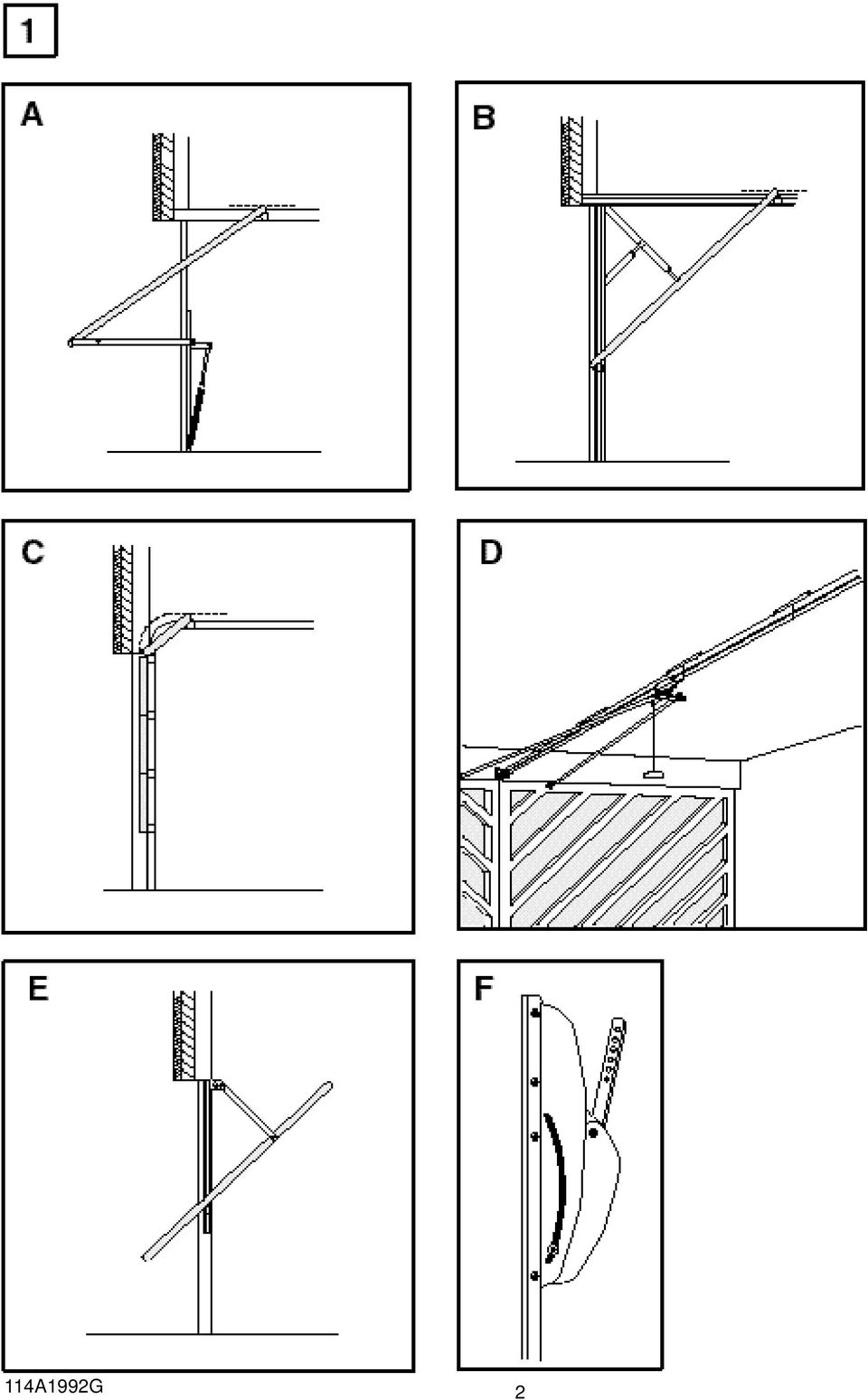
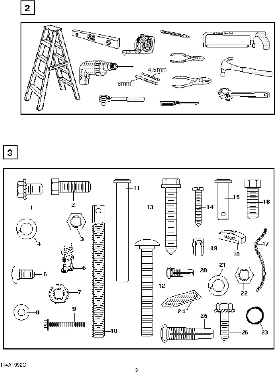
2 START BY READING THESE IMPORTANT SAFETY RULES These safety alert symbols mean Caution a personal safety or property damage instruction. Read these instructions carefully. This garage door opener is designed and tested to offer reasonable safe service provided it is installed and operated in strict accordance with the following safety rules. Failure to comply with the following instructions may result in serious personal injury or property damage. Caution: If your garage has no service entrance door, Model 1702EML Outside Quick Release must be installed. This accessory allows manual operation of the garage door from outside in case of power failure. Keep garage door balanced. Sticking or binding doors must be repaired. Garage doors, door springs, cables, pulleys, brackets and their hardware are under extreme tension and can cause serious personal injury. Do not attempt to loose, move or adjust them. Call for garage door service. Do not wear rings, watches or loose clothing while installing or servicing a garage door opener. To avoid serious personal injury from entanglement, remove all ropes connected to the garage door before installing the door opener. Installation and wiring must be in compliance with your local building and electrical codes. Connect the power supply cord only to properly earthed mains. Lightweight doors or fiberglass, aluminum or steel must be substantially reinforced to avoid door damage. (See page 4.) The best solution is to check with your garage door manufacturer for an opener installation reinforcement kit. The safety reverse system test is very important. Your garage door MUST reverse on contact with a 50mm obstacle placed on the floor. Failure to properly adjust the opener may result in serious personal injury from a closing garage door. Repeat the test once a month and make any needed adjustments. This unit should not be installed in a damp or wet space. Door must not extend over public byway during operation. The force, as measured on the closing edge of the door, should not exceed 150 N (15kg). If the closing force is adjusted to more than 150 N, the Protector System must be installed. Do not use the force adjustments to compensate for a binding or sticking garage door. Excessive force will interfere with the proper operation of the Safety Reverse System or damage the garage door. Fasten the caution label adjacent to the lighted door control button as a reminder of safe operating procedures. Disengage all existing garage door locks to avoid damage to garage door. Install the lighted door control button (or any additional push buttons) in a location where the garage door is visible, but out of the reach of children. Do not allow children to operate push button(s) or remote control(s). Serious personal injury from a closing garage door may result from misuse of the opener. Activate opener only when the door is in full view, free of obstructions and opener is properly adjusted. No one should enter or leave the garage while the door is in motion. Do not allow children to play near the door. Use manual release only to disengage the trolley and, if possible, only when the door is closed. Do not use the red handle to pull the door open or closed. Disconnect electric power to the garage door opener before making repairs or removing covers. This product is provided with a power supply cord of special design which, if damaged, must be replaced by a power supply cord of the same type; such a power supply cord may be obtained from your local Chamberlain distributor and must be fitted by a specialist. 1-GB CONTENTS SAFETY RULES: Page 1 DOOR TYPES: Page 1 Illustration TOOLS REQUIRED: Illustration 2 HARDWARE PROVIDED: Page 1 Illustration 3 BEFORE YOU BEGIN: Page 2 COMPLETED INSTALLATION: Page 2 Illustration 4 1 ASSEMBLY: Page 2 Illustrations 5 INSTALLATION: Pages 3-4 Illustrations PROGRAMMING THE CODE: Page 4 Illustration 21 ADJUSTMENT: Pages 4-5 Illustrations INSTALL THE PROTECTOR (Optional): Page 5 Illustration OPERATION OF YOUR OPENER: Page 5 CARE OF YOUR OPENER: Page 5 PROBLEMS: Page 6 MAINTENANCE OF YOUR OPENER: Page 7 ACCESSORIES: Page 7 Illustration 26 SPECIFICATIONS: Page 7 RAIL ASSEMBLY & INSTALLATION PARTS LIST: Illustration 27 OPENER PARTS LIST: Illustration 28 DOOR TYPES 1 A. One-Piece Door with Horizontal Track Only B. One-Piece Door with Horizontal and Vertical Track Special door arm (F, The Chamberlain Arm ) required. See your dealer. C. Sectional Door with Curved Track See 20 B connect door arm. D. Double-wing door Special door arm required. See your dealer. E. Canopy door Special door arm (F, The Chamberlain Arm ) required. See your dealer. HARDWARE PROVIDED 3 Assembly Hardware: (1) Washered Screws (2) (2) Hex Screws (2) (3) Nuts (2) (4) Lock Washers (2) (5) Master Links (2) (6) Carriage Bolts (12) (7) Lock Nuts (12) (8) Flat Washers (2) (9) Hex Screws (2) (10) Trolley Threaded Shaft (1) (11) Clevis Pin (1) Installation Hardware: (12) Carriage Bolts (2) (13) Wood Screws (4) (14) Screws (2) (15) Clevis Pins (2) (16) Hex Screws (5) (17) Rope (18) Handle (19) Insulated Staples (20) Anchors (2) (21) Lock Washers (8) (22) Nuts (9) (23) Ring Fasteners (3) (24) Rail Grease (25) 8mm Anchors (4) (26) Sheet Metal Screws (2) 114A1991H

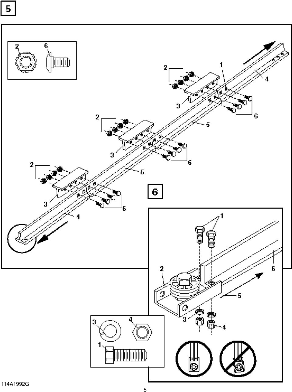
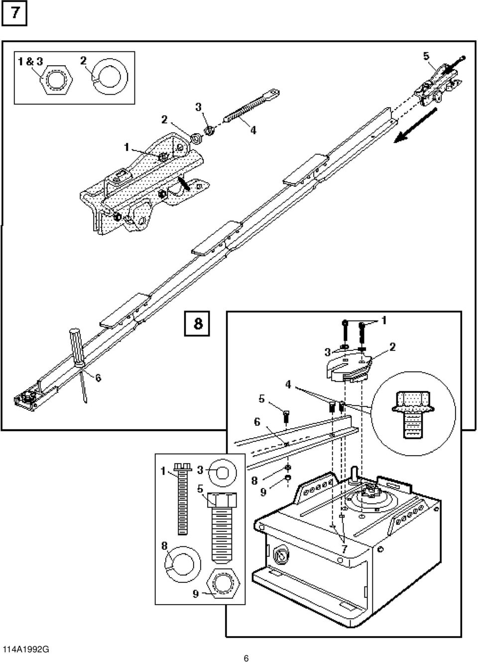
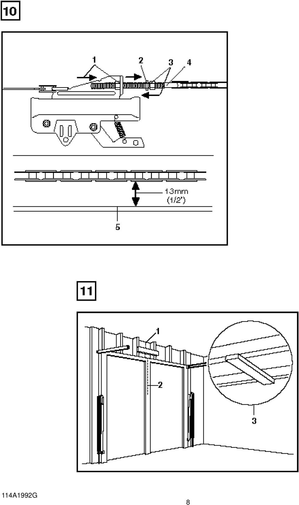
3 BEFORE YOU BEGIN: 1. Look at the wall or ceiling above the garage door. The header bracket must be securely fastened to structural supports. 2. Do you have a finished ceiling in your garage? If so, a support bracket and additional fastening hardware (not supplied) may be required. 3. Depending on your door's construction, you might need a special door arm. See your dealer. 4. Do you have an access door in addition to the garage door? If not, Model 1702EML Outside Quick Release Accessory is required. COMPLETED INSTALLATION As you proceed with the assembly, installation and adjustment proceedures in this manual, you may find it helpful to refer back to this illustration of a completed installation. (1) Cable Pulley Bracket (9) Manual Release (2) Trolley Rope & Handle (3) Chain & Cable (10) Curved Door Arm (4) T-rail (11) Straight Door Arm (5) Hanging Bracket (12) Door Bracket (6) Power Cord (13) Header Bracket (7) Opener (14) Trolley Release Arm (8) Light Lens ASSEMBLY SECTION 5 10 Important: If you have a canopy or dual-track door, you need to use the instructions packed with The Chamberlain Arm Accessory in conjunction with this Owner's Manual when assembling the T-rail. ASSEMBLE THE T-RAIL 5 Place rail pieces on flat surface for assembly. The center sections with tapered ends (5) are interchangeable. So are the end sections (4). Connect the braces (3) and lock nuts (2) from one side of the rails and insert the carriage bolts (6) from the opposite side. Then the trolley will not hit the lock nuts when it is installed. The square necks on the carriage bolts must be seated in square holes in rail sections (1). For canopy and dual-track doors, continue with the instructions in this manual until Step FASTEN T-RAIL & ATTACH CHAIN SPREADER Place packing material under the opener to protect the opener cover. For convenience, place a support under the cable pulley bracket end of rail. Remove the (2) washered screws (4) from the top of the opener. Align holes in back end of the T-rail with holes in opener (7). Fasten the rail to the opener with the same washered screws and tighten securely. Caution: Use only those screws! Use of any other screws will cause serious damage to the door opener. Attach the chain spreader (2) with hex screws (1) and flat washers (3). Insert a hex screw (5) into trolley stop hole in T-rail (6). Tighten securely with a lock washer (8) and nut (9). INSTALL THE CHAIN/CABLE Do not remove chain/cable from carton. Dispense a few inches of cable from carton and fasten to trolley with a master link. Master Link Procedure: Push pins of master link bar (5) through cable loop (6) and hole in front end of trolley (7). Push cap (2) over pins (8) and onto notches. Slide clip-on spring (1) over cap and onto pin notches until both pins are securely locked in place. Caution: Keep chain taut during installation to help prevent kinking. With the trolley against screwdriver, dispense chain/cable around pulley (4). Proceed back around a groove in chain spreader (9). (Chain installation for either the 6-tooth sprocket (11) or the 8-tooth sprocket (12) is based on door type.) All one-piece doors should use the 6-tooth sprocket. The opener sprocket teeth (10) must engage the chain. Use the second master link to connect the chain to the flat end of the threaded shaft (3). Check to make sure the chain is not twisted. Remove the screwdriver. TIGHTEN THE CHAIN/CABLE Spin inner nut (3) and lock washer (2) down threaded shaft (4). Check to make sure chain is not twisted. To tighten the chain, turn outer nut (1) in the direction shown. As you turn the nut, keep the chain from twisting. When chain is approximately 13mm (1/2") above the base of the T-rail (5) at midpoint, re-tighten inner nut. Sprocket noise can result if chain is either too loose or too tight. When installation is complete, you may notice some chain droop with the door closed. This is normal. If the chain returns to the position described above when the door is open, do not re-adjust the chain. During future maintenance, ALWAYS pull the manual release handle to disconnect trolley before adjusting chain GB INSTALL THE CABLE PULLEY BRACKET 6 Position cable pulley bracket (2) on the front section of T-rail (6). Fasten securely with: screws (1); lock washers (3) and nuts (4). When tightening the screws, be sure to keep bracket parallel to rail (5). Otherwise, rail may bow when opener is operated. ASSEMBLY OF YOUR OPENER IS NOW COMPLETE. INSTALL THE TROLLEY 7 Insert a screwdriver into trolley "stop" hole in the front end of T-rail (6). Attach trolley threaded shaft (4) to the trolley with: lock washer (2), and nuts (1 & 3). Slide trolley (5) along rail to the "stop". Note: If the trolley hits against any nuts on the T-rail, review rail assembly and reposition hardware. 114A1991H

4 INSTALLATION SECTION Wear protective goggles when working overhead to protect your eyes from injury. Disengage all existing garage door locks to avoid damage to the garage door. To avoid serious personal injury from entanglement, remove all ropes connected to the garage door before installing the opener. Installation of this product shall comply with ZH1/494, VDE 0700 Part 238, and VDE 0700 Part 1. It is recommended that the opener be installed 2,1m (7 feet) or more above the floor where space permits. POSITION THE HEADER BRACKET The header bracket must be rigidly fastened to a structural support of the garage. Reinforce the wall or ceiling with a 40mm (1-1/2") board if necessary. Failure to comply may result in improper operation of safety reverse system. You can attach the header bracket either to the header wall (1) or to the ceiling (3). Follow the instructions which will work best for your particular requirements. With the door closed, mark the vertical centerline (2) of the garage door. Extend line onto header wall above the door. Open door to highest point of travel. Draw an intersecting horizontal line on header wall 5cm (2") above high point to provide travel clearance for top edge of door. INSTALL THE HEADER BRACKET A. Wall Mount: Center the bracket (2) on the vertical guideline (1) with the bottom edge of the bracket on the horizontal line (6) (with the arrow pointing toward the ceiling). Mark either set of bracket holes (4 or 5). Do not use the holes designated for ceiling mount. Drill 4,5mm (3/16") pilot holes and fasten the bracket with wood screws (3). B. Ceiling Mount: Extend vertical guideline (1) onto the ceiling. Center the bracket (2) on the vertical mark no more than 150mm (6") from the wall. Make sure the arrow is pointing toward the wall. Mark holes designated for ceiling mount only (4). Drill 4,5mm (3/16") pilot holes and fasten the bracket with wood screws (3) HANG THE OPENER 15 The opener must be securely fastened to a structural support of the garage. Three representative installations are shown. Yours may be different. Hanging brackets (1) should be angled (Figure A) to provide rigid support. On finished ceilings, (Figure B) attach a sturdy metal bracket (not supplied) (4) to a structural support before installing the opener. For concrete ceiling mount, (Figure C), use concrete anchors (5) provided. On each side of opener measure the distance from the opener to the structural support (or ceiling). Cut both pieces of the hanging bracket to required lengths. Flatten one end of each bracket and bend or twist to fit the fastening angles. Do not bend at the bracket holes. Drill 4,5mm (3/16") pilot holes in the structural supports (or ceiling). Attach flattened ends of brackets to supports with wood screws (2). Lift opener and fasten to hanging brackets with screw, lock washer and nut (3). Check to make sure T-rail is centered over the door. REMOVE 25mm (1") board. Operate door manually. If door hits the rail, raise header bracket. Grease the top and underside of rail surface on which the trolley slides. A tube of grease is supplied. ATTACH MANUAL RELEASE ROPE & HANDLE 16 Thread one end of rope (1) through hole in top of red handle so "NOTICE" reads right side up as shown (3). Secure with an overhand knot (2). Knot should be at least 25mm (1") from end of the rope to prevent slipping. Thread other end of rope through hole in release arm of the outer trolley (4). Adjust rope length so that handle is 1,8m (6 feet) above the floor. Secure with an overhand knot. Note: If it is necessary to cut rope, heat seal cut end with a match or lighter to prevent fraying. CONNECT ELECTRIC POWER TO AVOID INSTALLATION DIFFICULTIES, DO NOT RUN THE GARAGE DOOR OPENER UNTIL INSTRUCTED TO DO SO. Connect the opener to a mains which is properly EARTHED according to the wiring instruction tag attached to power supply cord (and as specified by local code). Connect the door opener only to an outlet controlled by a double pole switch. 3-GB ATTACH T-RAIL TO HEADER BRACKET Position opener on garage floor below the header bracket. Use packing material to protect the cover. Note: To enable the T-rail to clear sectional door springs, it may be necessary to lift opener onto a temporary support. The opener must either be secured to a support or held firmly in place by another person. Raise T-rail until cable pulley and header brackets come together. Join with clevis pin (1). Insert ring fastener (2) to secure. POSITION THE OPENER Note: A 25mm (1") board (1) is convenient for setting an ideal door-to-t-rail distance (unless headroom is not sufficient). Raise the opener onto a stepladder. Open garage door. Place a 25mm (1") board (1) laid flat on the top section of door near the centerline as shown. Rest the T-rail on the board. If the raised door hits the trolley, pull down on the trolley release arm to disconnect the inner and outer trolley sections. The trolley can remain disconnected until connecting door arm to trolley is completed. 114A1991H INSTALL THE LIGHTED DOOR CONTROL BUTTON Locate push buttons where the garage door is visible, away from door and door hardware and out of the reach of children. Serious personal injury from a moving garage door may result from misuse of opener. Do not allow children to operate the lighted door control button or remote control transmitter. Fasten the caution label on the wall near the lighted door control button as a reminder of safe operating procedures. There are 2 screw terminals (1) on the back of the lighted door control button (2). Strip about 6mm (1/4") of insulation from bell wire (4). Separate wires enough to connect the white/red wire to terminal screw 1 and the white wire to terminal screw 2. Fasten the lighted door control button to an inside garage wall with sheet metal screws (3) provided. Drill 4mm (5/32") holes and use anchors (6) if installing into drywall. A convenient place is beside the service door and out of reach of children. Run the bell wire up the wall and across the ceiling to the garage door opener. Use insulated staples (5) to secure wire. The receiver terminal screws (7) are located on the back panel of the opener. Connect the bell wire to the terminal screws as follows: white/red to 1 and white to 2. 17
 or more above the floor where space permits.")
5 OPERATION OF THE LIGHTED DOOR CONTROL BUTTON Press to open or close the door. Press again to reverse the door during the closing cycle or to stop the door during opening cycle. INSTALL THE LIGHT AND LENS Install a 40 watt maximum light bulb (1) in the socket as shown. The light will turn on and remain lit for 4-1/2 minutes when power is connected. After 4-1/2 minutes it will turn off. Replace burned out bulbs with rough service light bulbs. Apply slight pressure on sides of the lens (2) and slide tabs (3) into slots (4) in the end panel. Reverse the procedure to remove the lens. FASTEN DOOR BRACKET If yours is a canopy or dual-track style garage door, a door arm conversion kit is required. Follow the installation instructions included with the replacement door arm. Exercise care in removing and assembling arm conversion kit. Keep fingers away from the sliding parts. Sectional and One-Piece Door Installation Procedure: 1. Center bracket (1) at the top of inside face of door as shown. Mark holes. 2. A. Wooden doors Drill 8mm (5/16") holes and fasten the door bracket with nut, lock washer, and carriage bolt (2). B. Sheet metal doors Fasten with sheet metal screws (3). C. One-piece door optional Fasten with sheet metal screws (3) PROGRAM YOUR OPENER & REMOTE Activate the opener only when door is in full view, free of obstruction and properly adjusted. No one should enter or leave garage while door is in motion. Do not allow children to operate push button(s) or remote(s). Do not allow children to play near the door. Your garage door opener receiver and remote control transmitter are set to a matching code. If you purchase additional remote controls, the garage door opener must be programmed to accept the new remote code. Program the Receiver to Match Additional Remote Control Codes 1. Press and hold the remote control push button (1). 2. Press and release the "Smart" button (2) on the back panel of the opener. The opener light will flash once. 3. Release the remote push button. Now the opener will operate when the remote control push button is pressed. If you release the remote control push button before the opener light flashes, the opener will not accept the code. To Erase all Remote Control Codes Press and hold the "Smart" button on the opener panel until the indicator light turns off (about 6 seconds). All the codes the opener has learned will be erased. To reprogram, repeat Steps 1 3 for each remote control in use. ADJUSTMENT SECTION GB CONNECT DOOR ARM TO TROLLEY Sectional Door Installation: Note door arm configuration in Figure B. One-Piece Door Installation: Procedure (Figure A). Connect straight door arm (1) and curved door arm sections (2) to obtain the longest possible length with hardware (3, 4 & 5). With door closed, connect straight door arm section to door bracket with a clevis pin (6). Secure with a ring fastener (7). Before connecting door arm to trolley, adjust travel limits. Limit adjustment screws are located on left side panel. Open Door Adjustment: Decrease up limit. Turn up limit adjustment screw counterclockwise 5-1/2 turns. Press door control button. Trolley will travel to full open position (8). Manually raise door to open position (parallel to floor) and lift door arm (9) to trolley. The arm should touch trolley just in back of door arm connector hole (10) as shown in solid line drawing. Increase up limit if necessary. One full turn equals 5cm (2") of door travel. Closed Door Adjustment: Decrease down limit. Turn down limit adjustment screw clockwise 5 complete turns. Press door control button. Trolley will travel to full closed position (11). Manually close door and lift door arm (12) to trolley. The arm should touch trolley just ahead of door arm connector hole (13) as shown in dotted line drawing. Decrease down limit if necessary. One full turn equals 5cm (2") of door travel. Connect Door Arm to Trolley: With door closed, connect curved arm to trolley with remaining clevis pin. Secure with ring fastener. Note: Lift door slightly to make connection if necessary. Run opener through a complete travel cycle. If door has a slight "backward" slant in full open position, decrease up limits until door is parallel to floor. 20 LIMIT ADJUSTMENT 22 Run the opener through a complete travel cycle. Limit adjustments are not necessary when the door opens and closes completely and doesn't reverse unintentionally in the fully closed position. Situations requiring limit adjustment are listed below. Run the opener through a complete travel cycle after each adjustment. Note: Repeated operation of the opener during adjustment procedures may cause motor to overheat and shut off. Allow a 15 minute cooling period after 5 continuous operations of the opener. Read the following carefully before proceeding to Force Adjustment. Use a screwdriver to make limit adjustments. If Door Doesn't Open Completely but Opens at Least 1,5m (5 feet): Increase up travel. Turn the up limit adjustment screw (1) clockwise. One turn equals 5cm (2") of travel. If door does not open at least 1,5m (5 feet): Adjust up (open) force. See Force Adjustment. If Door Doesn't Close Completely: If door arm is at maximum length, increase down travel. Turn down limit adjustment screw (2) counterclockwise. One turn equals 5cm (2") of travel. If the door still will not close completely, the header bracket is positioned too high. If Opener Reverses in Fully Closed Position: Decrease down travel. Turn down limit adjustment screw (2) clockwise. One turn equals 5cm (2") of travel. If Door Reverses when Closing and there is no Interference to Travel Cycle: Test door for binding. Pull manual release handle. Manually open and close door. If door is binding, call a door serviceman. If door is not binding or unbalanced, adjust down (close) force. 114A1991H

6 FORCE ADJUSTMENT 23 The force, as measured on the closing edge of the door, should not exceed 150 N (15kg). If the closing force is adjusted to more than 150 N, the Protector System must be installed. Do not use force adjustments to compensate for a binding or sticking garage door. Excessive force will interfere with proper operation of safety reverse system or damage garage door. Force Adjustment Controls (1 & 2) are located on the back panel of opener. If the force adjustments are set too light, door travel may be interrupted by nuisance reversals in down direction and stops in up direction. Weather conditions can affect the door movement, occasional adjustment may be needed. Maximum force adjustment range is 260 degrees, about 3/4 of a complete turn. Do not force controls beyond that point. Turn force adjustment controls with a screwdriver. Test Down (Close) Force: Grasp the door handle or door bottom when door is about halfway through down (close) travel. Door should reverse. (Reversal halfway through down travel does not guarantee reversal on a 50mm obstruction.) If the door is hard to hold or doesn't reverse, decrease down (close) force by turning the control (2) in a counterclockwise direction. Make small adjustments until door reverses normally. After each adjustment, run opener through a complete cycle. If Door Doesn't Open at Least 1,5m (5 feet): Increase up (open) force by turning the control (1) in a clockwise direction. Make small adjustments until door opens completely. Re-adjust up limit if necessary. After each adjustment, run opener through a complete travel cycle. If Door Reverses During Down (Close) Cycle: Increase down (close) force by turning the control (2) in a clockwise direction. Make small adjustments until door completes close cycle. After each adjustment, run the opener through a complete travel cycle. Do not increase the force beyond the minimum amount required to close the door. TEST THE SAFETY REVERSE SYSTEM The safety reverse system test is important. Garage door must reverse on contact with a 50mm obstacle laid flat on the floor. Failure to properly adjust opener may result in serious personal injury from a closing garage door. Repeat test once a month and adjust as needed. Procedure: Place a 50mm obstacle (1) laid flat on the floor under the garage door. Operate the door in the down direction. The door must reverse on the obstruction. If the door stops on the obstruction, it is not traveling far enough in the down direction. Increase the down limit by turning down limit adjustment screw counterclockwise 1/4 turn. Repeat test. When the door reverses on the 50mm obstacle, remove the obstruction and run the opener through a complete travel cycle. Door must not reverse in closed position. If it does, adjust Limits and Force and repeat safety reverse test. INSTALL THE PROTECTOR SYSTEM (See accessories) The force, as measured on the closing edge of the door, should not exceed 150 N (15kg). If the closing force is adjusted to more than 150 N, the Protector System must be installed. After opener has been installed and adjusted, The Protector System accessory can be installed. Instructions are included with this accessory. The Protector System provides an additional measure of safety against a small child being caught under a garage door. It uses an invisible beam which, when broken by an obstruction, causes a closing door to open and prevents an open door from closing and is strongly recommended for homeowners with young children. 114A1991H OPERATION OF YOUR OPENER Your opener can be activated by any of the following devices: The Lighted Door Control Button. Hold the button down until door starts to move. The Outside Keylock or Keyless Entry System (if you have installed either of these accessories). The Remote Control Transmitter. Hold the push button down until the door starts to move. Opening the Door Manually: Door should be fully closed if possible. Weak or broken springs could allow an open door to fall rapidly. Property damage or serious personal injury could result. The door can be opened manually by pulling the release handle down and back (toward the opener). To reconnect the door, pull the release handle straight down. Do not use the manual release handle to pull the door open or closed. When the Opener is Activated by Remote Control or Lighted Door Control Button: 1. If open, the door will close. If closed, the door will open. 2. If closing, the door will reverse. 3. If opening, the door will stop (allowing space for entry and exit of pets and for fresh air). 4. If the door has been stopped in a partially open position, it will close. 5. If an obstruction is encountered while closing, the door will reverse. 6. If an obstruction is encountered while opening, the door will stop. 7. The optional Protector System uses an invisible beam which, when broken by an obstruction, causes a closing door to open and prevents an open door from closing. It is STRONGLY RECOMMENDED for homeowners with young children. Allow a 15 minute cooling period after 5 continuous operations of the opener. The opener light will turn on: 1. when opener is initially plugged in; 2. when the power is interrupted; 3. when the opener is activated. The light turns off automatically after 4-1/2 minutes. Bulb size is 40 Watts maximum. CARE OF YOUR OPENER When properly installed, opener will provide high performance with a minimum of maintenance. The opener does not require additional lubrication. Limit and Force Adjustments: These adjustments must be checked and properly set when opener is installed. Only a screwdriver is required. Weather conditions may cause some minor changes in the door operation, requiring some re-adjustments, particularly during the first year of operation. Refer to the limit and force adjustments on pages 4 & 5. Follow the instructions carefully and repeat the safety reverse test after any adjustment. Remote Control Transmitter: The portable remote control may be secured to a car sun visor with the clip provided. Additional remotes can be purchased at any time for use in all vehicles using garage. Refer to Accessories.The receiver must be programmed to operate with any new remote. Remote Control Battery: The lithium batteries should produce power for up to 5 years. When the light becomes dim or does not come on, replace the battery. If transmission range lessens, check the battery test light. To Change Battery: To replace batteries, use the visor clip or screwdriver blade to pry open the case. Insert batteries positive side up. To replace cover, snap shut along both sides. Do not dispose of the old battery with household waste. Take batteries to a proper disposal center. 5-GB

7 HAVING A PROBLEM? 1. Opener doesn't operate from either door control or remote: Does the opener have electric power? Plug lamp into outlet. If it doesn't light, check the fuse box or the circuit breaker. (Some outlets are controlled by a wall switch.) Have you disengaged all door locks? Review installation instruction warnings on page 1. Is there a build-up of ice or snow under door? The door may be frozen to ground. Remove any obstruction. The garage door spring may be broken. Have it replaced. Repeated operation may have tripped the overload protector in the motor. Wait 15 minutes. Try again. 2. Opener operates from remote but not from door control: Is door control button lit? If not, remove the bell wire from the opener terminals. Short the red and white terminals by touching both terminals at the same time with a piece of wire. If the opener runs, check for a faulty wire connection at the door control, a short under the staples, or a broken wire. Are wiring connections correct? Review page Door operates from door control but not from remote: Check the battery test light. Replace battery if necessary. If you have two or more remotes and only one operates, review receiver programming procedures on page 4. Is the door control button flashing? The opener receiver must re-learn the remote control code. Follow the instructions on page Remote has short range: Is battery installed? Check battery test light. If the light is dim, change the battery. Change the location of the remote control on the car. A metal garage door, foil-backed insulation or metal siding will reduce the transmission range. 5. Door reverses for no apparent reason and opener light doesn't blink: Is something obstructing the door? Pull manual release handle. Operate door manually. If it is unbalanced or binding, call for professional garage door service. Clear any ice or snow from garage floor area where garage door closes. Review Force Adjustment. If door reverses in FULLY CLOSED position, decrease travel limits. Repeat safety reverse test after adjustment is complete. The need for occasional adjustment of the force and limit settings is normal. Weather conditions in particular can affect door travel. 6. Door reverses for no apparent reason and opener light blinks for 5 seconds after reversing: Check The Protector System (if you have installed this accessory). If the light is blinking, correct alignment. 7. Opener noise is disturbing in living quarters of home: If operational noise is a problem because of proximity of the opener to the living quarters, Vibration Isolator Kit 41A3263 can be installed. This kit was designed to eliminate the "sounding board effect" and is easy to install. 114A1991H 8. The garage door opens and closes by itself: Is there a neighbor with a garage door opener using the same frequency code? Change your code. Make sure remote push button is not stuck "on". 9. Door stops but doesn't close completely: Review Travel Limits Adjustment. Repeat safety reverse test after any adjustment of door arm length, close force or down limit. 10. Door opens but won't close: Check The Protector System (if you have installed this accessory). If the light is blinking, correct alignment. If opener light does not blink and it is a new installation, check the down force. Repeat the safety reverse test after the adjustment is complete. 11. Opener light does not turn ON: Replace light bulb (40 Watts maximum). Replace burned out bulbs with rough service light bulbs. 12. Opener light does not turn OFF: There may be a defective earth at the ceiling or wall receptacle. The unit must be earthed. 13. Opener strains or maximum force is needed to activate door: Door may be unbalanced or springs are broken. Close door and use manual release rope and handle to disconnect trolley. Open and close door manually. A properly balanced door will stay in any point of travel while being supported entirely by its springs. If it does not, call for professional garage door service to correct the problem. Do not increase the force to operate the opener. 14. Opener motor hums briefly, then won't work: Garage door springs are broken. SEE ABOVE. If problem occurs on first operation of opener, door is locked. Disable door lock. If chain was removed and reinstalled, the motor may be out of phase. Remove chain; cycle motor to down position. Observe drive sprocket. When it turns in clockwise direction and stops in down position, re-install chain. Repeat safety reverse test after adjustment is complete. 15. Opener won't activate due to power failure: Pull manual release rope and handle down and back to disconnect trolley. Door can be opened and closed manually. When the power is restored, pull the manual release handle straight down. The next time the opener is activated, the trolley will reconnect. The Outside Quick Release accessory 1702EML (if fitted) disconnects the trolley from outside the garage in case of power failure. 16. The chain droops or sags: It is normal for the chain to droop slightly in the closed door position. Use the manual release rope and handle to disconnect the trolley. If the chain returns to the normal height when the trolley is disengaged and the door reverses on a 50mm obstacle laid flat, no adjustments are needed. 6-GB

8 MAINTENANCE OF YOUR OPENER Once a Month: Repeat safety reverse test. Make any necessary adjustments. Manually operate door. If it is unbalanced or binding, call for professional garage door service. Check to be sure door opens and closes fully. Adjust Limits and/or Force if necessary. Twice a Year: Check chain tension. Disconnect trolley first. Adjust if necessary. Once a Year: Oil door rollers, bearings and hinges. The opener does not require additional lubrication. Do not grease the door tracks. ACCESSORIES 26 (1) Model 4330EML...Single-Function Remote Control (2) Model 4333EML...3-Function Remote Control (3) Model 4335EML...3-Function Mini Remote Control (4) Model 845EML...Multi-Function Door Control Panel (5) Model 75EML...Lighted Door Control Button (6) Model 747EML...Keyless Entry System (7) Model 760EML...Outside Keylock (8) Model 1702EML...Outside Quick Release (9) Model 770EML...The Protector System (10) Model 1703EML...The Chamberlain Arm (11) Model 1EML...Door Handle Quick Release (12) Model 34EML...2-Position Key Switch Flush Mount Model 41EML...2-Position Key Switch Surface Mount WIRING INSTRUCTIONS FOR ACCESSORIES Keyless Entry System To opener terminals: Red-1 and White-2 Lighted Push Button To opener terminals: Red-1 and White-2 Outside Keylock To opener terminals: Red-1 and White-2 Protector System To opener terminals: White-2 and Black-3 Wall Control Panel To opener terminals: Red-1 and White-2 REPLACEMENT PARTS SPECIFICATIONS Max. Pull Force...800N Watts Motor Type...Permanent split capacitor Speed rpm Volts Volts AC-50Hz Only Drive Mechanism Gears...16:1 worm gear reduction Drive...Chain/cable with one-piece trolley on steel T-rail. Length of Travel...Adjustable to 2,29m (7-1/2 feet) Travel Rate...178mm (7 inches) per second Lamp...On when door starts, off 4-1/2 minutes after stop. Door Linkage...Adjustable door arm. Pull cord trolley release. Safety Personal...Push button and automatic reversal in down direction. Push button and automatic stop in up direction. Electronic...Independent up and down force adjustment screws. Electrical...Motor overload protector and low voltage push button wiring. Limit Device...Circuit actuated by limit nut. Limit Adjustment...Screwdriver adjustment on side panel. Start Circuit...Low voltage push button circuit. Dimensions Length (Overall)...3,11m (122-1/2 inches) Headroom Required...5cm (2 inches) Hanging Weight...14,5 kg (32 lb) Receiver Memory Registers Computer Code...12 Code Switch...1 Keypad GB Declaration of Conformity Automatic Garage Door Opener...Model G4000ML is in conformity to the applicable sections of Standards...EN , EN55014, EN , ETS , & EN per the provisions & all amendments of the EU Directives /5/EC, 73/23/EEC, 89/336/EEC Declaration of Incorporation Automatic Garage Door Opener Model No. G4000ML, when installed and maintained according to all the Manufacturer s instructions in combination with a Garage Door, which has also been installed and maintained according to all the Manufacturer s instructions, meet the provisions of EU Directive 89/392/EEC and all amendments. I, the undersigned, hereby declare that the equipment specified above and any accessory listed in the manual conforms to the above Directives and Standards. THE CHAMBERLAIN GROUP, INC. Elmhurst, IL USA May, 2003 Barbara P. Kelkhoff Manager, Reg. Affairs 2003, Chamberlain GmbH 114A1991H All rights reserved Printed in Mexico
 Model 4333EML...3-Function Remote Control (3) Model 4335EML...3-Function Mini Remote Control (4) Model 845EML...Multi-Function Door Control Panel (5) Model 75EML.")
9 D F GB DK E GR I N NL P S SF Abbildungen Garagentoröffner Modell MotorLift 4000 Figures Modèle MotorLift 4000 de ouvre-porte de garage Illustrations Garage Door Operator Model MotorLift 4000 Illustration Model MotorLift 4000 Garageportsåbner Ilustraciones Abridor de la puerta de garage, Modelo MotorLift 4000 Ì MË ÓÈÛÌfi AÓÔ ÁÌ ÙÔ Î Ú fiappleôúù, MÔÓÙ ÏÔ MotorLift 4000 Illustrazioni Apriporta per garage Modello MotorLift 4000 Afbeeldingen Model MotorLift 4000 Garagedeuropener Illustrasjon Garasjeportåpner, Modell MotorLift 4000 Figuras Operador automático de porta, Modelo MotorLift 4000 Bild. Garageportöppnare Modell MotorLift 4000 Kuvat Autotallin oven avaaja, Malli MotorLift A1992G

10 114A1992G 2
11 114A1992G 3
12 114A1992G 4

13 114A1992G 5
14 114A1992G 6
15 114A1992G 7

16 114A1992G 8
17 114A1992G 9

18 114A1992G 10

19 114A1992G 11

20 114A1992G 12

21 KG KG A1992G 13
22 EML 4333EML 4335EML 845EML LOCK LIGHT 4 75EML EML EML 760EML 1702EML 770EML EML 34EML/41EML A1992G 14
23 27 Pb Cd Hg 41A A B A238 10A20 183B112 41A B B113 83A4 41A4330 CEILING MOUNT ONLY UP 41A C128 41A B A B374 1A995 NOTICE 41A B B35 178B34 114A1992G 15
24 28 41A C B66-2 (Schuko) 26B62-3 (UK) 41A A A B114 41A A4945B 41A A A A B D34 41A C A A D A R A1992G 2003, Chamberlain GmbH All rights reserved
GARAGE DOOR OPENER ASSEMBLY/INSTALLATION MANUAL
 The Chamberlain Group, Inc. 845 Larch Avenue Elmhurst, Illinois 60126-1196 www.chamberlain.com GARAGE DOOR OPENER ASSEMBLY/INSTALLATION MANUAL Please read this manual and the enclosed safety materials
GARAGE DOOR OPENER Model 3265 1/2 HP
 The Chamberlain Group, Inc. 845 Larch Avenue Elmhurst, Illinois 60126-1196 www.liftmaster.com GARAGE DOOR OPENER Model 3265 1/2 HP For Residential Use Only Owner s Manual Please read this manual and the
Models HD920EV HD930EV LW5000EV WD962KEV WD962KPEV WD962MLEV 349544
 .. Belt Drive Battery Backup Garage Door Opener Models HD920EV HD930EV LW5000EV WD962KEV WD962KPEV WD962MLEV 349544 FOR RESIDENTIAL USE ONLY Please read this manual and the enclosed safety materials carefully!
Models HD920EV HD930EV LW5000EV WD962KEV WD962KPEV WD962MLEV 349544
 .. Belt Drive Battery Backup Garage Door Opener Models HD920EV HD930EV LW5000EV WD962KEV WD962KPEV WD962MLEV 349544 FOR RESIDENTIAL USE ONLY Please read this manual and the enclosed safety materials carefully!
Owners & Installation Manual for the Sheridan, Mountainair, Pine Valley and Old Forge Ceiling Fan Family
 Owners & Installation Manual for the Sheridan, Mountainair, Pine Valley and Old Forge Ceiling Fan Family Part of the Kiva Lighting Family Custom Lighting and Fans Since 1992 1312 12th St NW Albuquerque,
TABLE OF CONTENTS. I. TROUBLESHOOTING... 2 - Section 1.01: Common Problems/Solutions... 2
 BAL Accu-Slide System I. Table of Contents TABLE OF CONTENTS I. TROUBLESHOOTING... 2 - Section 1.01: Common Problems/Solutions... 2 II. GETTING STARTED... 5 - Section 2.01: Tools You Will Need... 5 - Section
Installation and operating instructions for Merlin garage door opener Model MR800
 professional professional Installation and operating instructions for Merlin garage door opener Model MR800 www.chamberlainanz.com N966 Installation and operating instructions for Merlin garage door opener
Garage Door Opener. Model 8500. For Residential and Light Duty Commercial Use Install On Sectional Doors With Torsion Assemblies Only
 Garage Door Opener Model 8500 For Residential and Light Duty Commercial Use Install On Sectional Doors With Torsion Assemblies Only See Page 18 for Details This product is intended for installation only
Table of Contents. www.hunterfan.com. What to Expect with. Preparation. Tools Needed. Wiring. Hanging the Fan. Blades. Motor Housing.
 www.hunterfan.com Table of Contents What to Expect with Your Installation 30 inches Hanging the Fan Wiring 8 Maintenance, Operation & Cleaning Light Kit 13??? 14 1 9 Troubleshooting 11 5 Blades Motor Housing
JANUS INTERNATIONAL CORPORATION INSTALLATION INSTRUCTIONS Pantheon Mini Operator
 JANUS INTERNATIONAL CORPORATION INSTALLATION INSTRUCTIONS Pantheon Mini Operator The Janus Pantheon mini operator does not typically require the provision of any additional site requirements other than
1. SAFETY RULES. 8. Avoid placing objects in the path of the blades.
 1 1. SAFETY RULES 1. To reduce the risk of electric shock, insure electricity has been turned off at the circuit breaker or fuse box before beginning. 2. All wiring must be in accordance with the National
Cable Drum Installation
 20 Cable Drum Installation COUNTERBALANCE None Shake the TorqueMaster spring tube gently to extend the winding shafts out about 5" on each side. For single spring applications, there will be no left hand
ColdGuard Bi-PARTING DOOR INSTALLATION INSTRUCTIONS
 EHD TRACK LEVEL, (SET LEVEL ON PLASTIC HEADER. DO NOT PLACE LEVEL ON ALUMINUM TRACK.) TRACK IS FLUSH WITH TOP OF HEADER JUNCTION BOX IDLER PULLEY LOCATOR PINS LOCATOR PINS OPERATOR DOOR STOP JUNCTION BOX
1. SAFETY RULES WARNING TO REDUCE THE RISK OF FIRE, ELECTRIC SHOCK OR PERSONAL INJURY, MOUNT FAN TO OUTLET BOX MARKED "ACCEPTABLE FOR FAN SUPPORT".
 1 1. SAFETY RULES 1. To reduce the risk of electric shock, insure electricity has been turned off at the circuit breaker or fuse box before beginning. 2. All wiring must be in accordance with the National
FRONT BUMPER INSTALLATION INSTRUCTIONS 2007-2011 DODGE / MERCEDES SPRINTER
 Aluminess Products Inc 9402 Wheatlands Ct. #A Santee, CA 92071 619-449-9930 FRONT BUMPER INSTALLATION INSTRUCTIONS 2007-2011 DODGE / MERCEDES SPRINTER Please read before beginning Stainless steel hardware
Owner s Guide and Installation Manual. Vancouver Model Name. 21321, 21328 Model No. English Español
 For Your Records and Warranty Assistance For reference, also attach your receipt or a copy of your receipt to the manual. Vancouver Model Name 21321, 21328 Model No. Type A Models Owner s Guide and Installation
M-4700 M-4500. Owner s Manual contains: installation, operating, maintenance, & warranty instructions. For residential use only.
 Digital Intelligence for the Garage M-4700 M-4500 Owner s Manual contains: installation, operating, maintenance, & warranty instructions. For residential use only. Marantec America Corporation 675 Heathrow
BUILT-IN DISHWASHER INSTALLATION INSTRUCTIONS
 BUILT-IN DISHWASHER INSTALLATION INSTRUCTIONS PLEASE READ COMPLETE INSTRUCTIONS BEFORE YOU BEGIN LEAVE INSTALLATION INSTRUCTIONS AND USER'S GUIDE WITH OWNER ALL ELECTRIC WIRING AND PLUMBING MUST BE DONE
MGB Chrome Bumper Conversion
 MGB Chrome Bumper Conversion Installation Instructions For 1974 1/2-1980 MGB This kit requires cutting, welding, and painting. Professional installation recommended. Note: Every MGB body is slightly different
Installation Instructions For Slider Casement Air Conditioners
 Installation Instructions For Slider Casement Air Conditioners NOTE: These instructions describe installation in a typical wood framed window with a wood SLIDE-BY sash, or installation in a metal CASEMENT
Ceiling Fan Installation Instructions
 Ceiling Fan Installation Instructions 1525..series OWNER S MANUAL READ AND SAVE THESE INSTRUCTIONS Total fan wieght with light kit 1-1525-CUL-English INSTALLATION CH-545 Safety Tips WARNING: TO REDUCE
Installation Instructions
 READ BEFORE INSTALLING UNIT For Slider Casement Air Conditioners To avoid risk of personal injury, property damage, or product damage due to the weight of this device and sharp edges that may be exposed:
LUCCI AIRFUSION QUEST II CEILING FAN
 LUCCI AIRFUSION QUEST II CEILING FAN WITH IR REMOTE INSTALLATION OPERATION MAINTENANCE WARRANTY INFORMATION CAUTION READ INSTRUCTIONS CAREFULLY FOR SAFE INSTALLATION AND FAN OPERATION. V1.0 QUEST II IR
OWNER S MANUAL Table Tennis Table Patent Pending
 OWNER S MANUAL Table Tennis Table Patent Pending Be sure to write your model number and serial number here for future reference. You can find these numbers printed on the bottom of the table. MODEL # T8179
INSTALLATION INSTRUCTION SPEC. SHEET 7/00. City of New York Calendar #40747 ETL LISTED UNDER U.L. STD. 2108 LOW VOLTAGE TRACK LIGHTING SYSTEM
 7/00 INSTALLATION INSTRUCTION SPEC. SHEET 99052 99063 City of New York Calendar #40747 Copyright c 2000 ALFA Lighting, Inc. All rights reserved. Call:1-415-975-8080 QUICK JACK QJS R LISTED 9901483 ETL
Andersen Electric Window Opener for Andersen Awning and Roof Windows
 W A Electric Window Opener Electric Window Opener for Awning and Roof Windows Congratulations! You have just purchased one of the many fine products. For ease of installation and continued enjoyment of
Model 2300DR Installation Guide
 Model 2300DR Installation Guide POWER ACCESS CORPORATION P.O. BOX 1050 170 MAIN STREET NEW HARTFORD, CT 06057 800-344-0088 WEBSITE: www.power-access.com EMAIL: salesinfo@power-access.com 1 STANDARD PARTS
Navico-Northstar 2kW JRC Radar Package, Scanner Cable Removal and Replacement
 Navico-Northstar 2kW JRC Radar Package, Scanner Cable Removal and Replacement This work instruction describes the methods and means for which to remove and reinstall optional scanner cable configurations
Roll-Up Door Maintenance Guide
 R Roll-Up Door Maintenance Guide Cable Replacement on Two Spring Type Balancer Page 1 Panel Replacement - Removable Roller Cover Type Bottom Panel Page 1 Panel Replacement - Removable Roller Cover Type
MBSAW. Meat Cutting Band Saw With Meat Grinder Assembly & Operating Instructions
 06/2011 MBSAW Meat Cutting Band Saw With Meat Grinder Assembly & Operating Instructions READ ALL INSTRUCTIONS AND WARNINGS BEFORE USING THIS PRODUCT. This manual provides important information on proper
Small Flat Panel Lift Arm FSA-1004 and KSA-1004
 I N S T A L L A T I O N I N S T R U C T I O N S Small Flat Panel Lift Arm FSA-1004 and KSA-1004 The Lift Arm is an accessory that can be used with a broad range of Small Flat Panel Displays. The allows
Fleck 4650. Service Manual INSTALLATION AND START-UP PROCEDURE TABLE OF CONTENTS JOB SPECIFICATION SHEET
 Fleck 4650 Service Manual TABLE OF CONTENTS JOB SPECIFICATION SHEET...1 INSTALLATION AND START-UP PROCEDURE...1 CONTROL VALVE DRIVE ASSEMBLY...2 CONTROL DRIVE ASSEMBLY FOR CLOCK...3 BYPASS VALVE ASSEMBLY...4
Ceiling Mounted Folding Attic Ladders Installation Instructions
 Ceiling Mounted Folding Attic Ladders Installation Instructions WARNING Before you start installing your new Louisville Ceiling Mounted Folding Attic Ladder, you must read and understand the following:
Installation Instructions
 Installation Instructions READ BEFORE INSTALLING UNIT For Low Profile Window Air Conditioner INSTALLATION WARNINGS AND CAUTION Carefully read the installation manual before beginning. Follow each step
CortezTM A Kichler Décor Ceiling Fan
 CortezTM A Kichler Décor Ceiling Fan Kichler Lighting 7711 East Pleasant Valley Road P.O. Box 318010 Cleveland, Ohio 44131-8010 Customer Service 866.558.5706 8:30 AM to 5:00 PM EST, Monday - Friday Instruction
TECHNICAL INFORMATION
 TECHNICAL INFORMATION Models No. 2012NB Description 304mm (12") Automatic Thickness Planer CONCEPTION AND MAIN APPLICATIONS * Compact and light weight (27 Kg./59 lbs) automatic thickness planer for easier
INSTALLATION AND OPERATING INSTRUCTIONS For Model GL1 Gate Locks
 Securitron Magnalock Corp. www.securitron.com ASSA ABLOY, the global leader Tel 800.624.5625 techsupport@securitron.com in door opening solutions INSTALLATION AND OPERATING INSTRUCTIONS For Model GL1 Gate
1000-LB. TRAILER JACK OWNER S MANUAL
 1000-LB. TRAILER JACK OWNER S MANUAL WARNING: Read carefully and understand all INSTRUCTIONS before operating. Failure to follow the safety rules and other basic safety precautions may result in serious
INSTALL/REMOVAL INSTRUCTIONS: WINDOW REGULATOR
 REMOVAL/INSTALL OF WINDOW REGULATOR (741-306) Honda Accord 2003 07 General Tech Tips: Use painter s tape rather than duct tape to secure window. It will not damage paint or leave sticky residue. A plastic
PRODUCT: WASHER / WASHER-DRYER COMBO MODEL: AW 120 / AW 122 / AW 125 AWD 120 / AWD 121 / AWD 129
 PRODUCT: WASHER / WASHER-DRYER COMBO MODEL: The information included in this Splendide Repair Manual may change without notice. Please see our web site www.splendide.com/service/docs.html for updates,
ATS Overhead Table Shelf System INSTRUCTION MANUAL
 ATS Overhead Table Shelf System INSTRUCTION MANUAL ATS Overhead Table Shelf System Instruction Manual Warranty Newport Corporation warrants this product to be free of defects in material and workmanship
I BEAM TRACK INSTALLATION
 PDQ 0/700 FESTOON SYSTEM INSTALLATION AND MAINTENANCE INSTRUCTIONS INTRODUCTION The PDQ Festoon System was designed to run on one of three sizes of I-beams: S x., S8 x 8. and S x.. System trolleys must
Your Simple Guide to Battery. www.firstalertpro.com. Replacement. Customer Care: 1-800-852-0086. www.firstalertpro.
 Previous Menu Your Simple Guide to Battery www.firstalertpro.com Replacement p e t s ts ep -by Customer Care: 1-800-852-0086 FA/1565 9/00 www.firstalertpro.com Table of Contents: page Introduction...............................
UPLIFT Height Adjustable Standing Desk (T-Frame) DIRECTIONS FOR ASSEMBLY AND USE - - ALSO - - Watch our assembly video
 DIRECTIONS FOR ASSEMBLY AND USE - - ALSO - - Watch our assembly video") UPLIFT Height Adjustable Standing Desk (T-Frame) DIRECTIONS FOR ASSEMBLY AND USE - - ALSO - - Watch our assembly video http://bit.ly/9ywwh! CAUTION MAKE SURE NO OBSTACLES ARE IN THE DESK S PATH AND ALL
UPLIFT Height Adjustable Standing Desk (T-Frame) DIRECTIONS FOR ASSEMBLY AND USE - - ALSO - - Watch our assembly video http://bit.ly/9ywwh! CAUTION MAKE SURE NO OBSTACLES ARE IN THE DESK S PATH AND ALL
758 Heavy-duty Ratchet Guy Wire Cutter
 INSTRUCTION MANUAL 758 Heavy-duty Ratchet Guy Wire Cutter Read and understand all of the instructions and safety information in this manual before operating or servicing this tool. Register this product
Drive shaft, servicing
 Volkswagen Passat B6 - Drive shaft, servicing Стр. 1 из 41 40-7 Drive shaft, servicing Drive shafts, overview I - Assembly overview: Drive axle with CV joint VL100 40-7, Drive axle with CV joint VL100,
Installation Instructions
 Installation Instructions Built-In Dishwasher If you have questions, call 1-800-4-MY-HOME (1-800-469-4663) or visit our website at: www.sears.com BEFORE YOU BEGIN Read these instructions completely and
Operating Instructions Bedienungsanleitung Mode d emploi
 Operating Instructions Bedienungsanleitung Mode d emploi DW 400 www.bron-kobold.com Operating instructions DW 400 Before use Please read all the information contained in these operating instructions carefully.
EZ-Steer Assisted Steering System
 EZ-Steer Assisted Steering System Installation Instructions Platform Kit P/N 53059-54 Case IH CVX 1135 CVX 1145 CVX 1155 CVX 1170 CVX 1190 CVX 1195 CVX 135 CVX 145 CVX 155 CVX 175 CVX 195 New Holland TVT
UB1 AIR CONDITIONING UNIT INSTALLATION INSTRUCTIONS
 UB1 AIR CONDITIONING UNIT INSTALLATION INSTRUCTIONS INSTALLATION INSTRUCTIONS: Carefully read these instructions before installing your new air-conditioner. AUSTRALIAN AUTOMOTIVE AIR AL00500054E 1 Table
Original Assembly Guide
 TCT Multipurpose Single Bevel Sliding Compound Mitre Saw Original Assembly Guide Read instructions before assembling this tool. Table of Contents GB Assembly Guide Read instructions before assembling this
Build Your Own Solar Car Teach build learn renewable Energy! Page 1 of 1
 Solar Car Teach build learn renewable Energy! Page 1 of 1 Background Not only is the sun a source of heat and light, it s a source of electricity too! Solar cells, also called photovoltaic cells, are used
BILLET HEADLAMP WITH SHORT/TALL MOUNTS
 -J099 REV. 00-0- BILLET HEADLAMP WITH SHORT/TALL MOUNTS GENERAL Kit Number 9-0, 9-0 Models Kit 9-0 is a -/ inch headlamp and kit 9-0 is a -/ inch headlamp. Both kits will fit the models listed in Table.
Atlanta CAUTION READ INSTRUCTIONS CAREFULLY FOR SAFE INSTALLATION AND FAN OPERATION. IF UNSURE CONSULT A QUALIFIED ELECTRICIAN
 OWNERS INSTRUCTION MANUAL 30 /76cm Atlanta INSTALLATION OPERATION MAINTENANCE CAUTION READ INSTRUCTIONS CAREFULLY FOR SAFE INSTALLATION AND FAN OPERATION. IF UNSURE CONSULT A QUALIFIED ELECTRICIAN PAGE
IMPORTANT INSTRUCTIONS & OPERATING MANUAL. Houston 50 Inch Electric Wall Mounted Fireplace Black / White
 IMPORTANT INSTRUCTIONS & OPERATING MANUAL Houston 50 Inch Electric Wall Mounted Fireplace Black / White Model Number:MFE5050BK Model Number:MFE5050WH Read these instructions carefully before attempting
GSM-EXT Cable Assembly Installation Guide
 GSM-EXT Cable Assembly Installation Guide For Documentation and Online Support: http://www.security.honeywell.com/hsc/resources/mywebtech General Information The GSM-EXT cable assembly is used to connect
Operating instructions. SCORP 220 Plus SCORP 360. Pipe Cutter. Code 790 014 762 Machine-no.:
 precision. power. simplicity. Operating instructions Pipe Cutter SCORP 220 Plus SCORP 360 Code 790 014 762 Machine-no.: All rights reserved, in particular the rights of duplication and distribution as
Cooktop Low-Profile Ventilation Hoods
 INSTALLATION GUIDE Cooktop Low-Profile Ventilation Hoods Contents Wolf Cooktop Low-Profile Ventilation Hoods........ 3 Cooktop Low-Profile Hood Specifications.......... 4 Cooktop Low-Profile Hood Installation............
Express5800/120Ed. Rack Mount Kit Installation Procedures PN: 455-01607-001
 Express5800/120Ed Rack Mount Kit Installation Procedures PN: 455-01607-001 Proprietary Notice and Liability Disclaimer The information disclosed in this document, including all designs and related materials,
Overview PARTS LIST. B. Lever mounting base C. Flush handle assembly D. Grey/Blue float stop E. Grey float (Full Flush) F. Flush valve washer
 F. Flush valve washer") Overview READ ENTIRE INSTRUCTIONS BEFORE STARTING INSTALLATION PARTS LIST A. Flush valve B. Lever mounting base C. Flush handle assembly D. Grey/Blue float stop E. Grey float (Full Flush) F. Flush valve
Overview READ ENTIRE INSTRUCTIONS BEFORE STARTING INSTALLATION PARTS LIST A. Flush valve B. Lever mounting base C. Flush handle assembly D. Grey/Blue float stop E. Grey float (Full Flush) F. Flush valve
Oceanscience Cable Chimp II Cableway ROV System User Guide and Warranty
 Oceanscience Cable Chimp II Cableway ROV System User Guide and Warranty Page 1 Table of Contents Introduction Page 3 Overview Page 3 Setup and Operation Page 5 Remote Control Page 6 Power Management Page
Speed-Mat Rectangle Cutter
 Speed-Mat Rectangle Cutter 1 Honeycomb baseboard. 2 Left hold down. 14 3 Bottom hold down. 4 4 Left / right rule. 8 5 8 5 Left / right rule pointer. 1 6 Top / bottom rule. 7 Top / bottom rule pointer.
IMPORTANT SAFETY RULES TO FOLLOW
 WARNING FLOOR & CARPET CLEANER Any piece of equipment can be dangerous if not operated properly. YOU are responsible for the safe operation of this equipment. The operator must carefully read and follow
Trillium 40 Axis Spring Tensioner Wire Replacement Instructions
 Trillium 40 Axis Spring Tensioner Wire Replacement Instructions 1 Overview The objective is to replace the broken axis spring tensioner wire. This requires the following tasks: 1. Remove the seismometer
AerAtron. Ceiling fans
 AerAtron Ceiling fans User Manual & Technical Specifications Models: e502 & e503 Australian edition 2011 Instructions...3 General precautions...3 Location and installation requirements for your fan...3
POWER LOCK KIT GENERAL INSTALLATION -J04427 REV. 2007-12-04. Kit Number. Models. Additional Parts Required. Kit Contents
 -J0 REV. 00--0 POWER LOCK KIT GENERAL Kit Number -0, 0-0 Models For model fitment information, please see the P&A Retail Catalog or the Parts and Accessories section of www.harleydavidson.com (English
Rack installation instructions
 Rack installation instructions Review the documentation that comes with the rack cabinet for safety and cabling information. Before you install the server in a rack cabinet, review the following guidelines:
Table of Contents WARNING SYMBOLS AND DEFINITIONS
 Table of Contents SAFETY INSTALLATION OPERATION MAINTENANCE Safety... 2 Specifications... 4 Installation... 5 Operation... 8 WARNING SYMBOLS AND DEFINITIONS Maintenance... 9 Parts List and Assembly Diagram...
54 LinkTM. Instruction Manual. Includes our new CoolTouch Control System Looks permanent, but goes wherever you go! U.S.
 54 LinkTM Includes our new CoolTouch Control System TM Looks permanent, but goes wherever you go! U.S. Patent Pending A Kichler Décor ceiling fan HIGH EFFICIENCY DC MOTOR Kichler Lighting 7711 East Pleasant
DTM04 TANK MONITOR DTM08 TANK MONITOR Dtm12 TANK MONITOR. Installation and Operation Manual
 DTM04 TANK MONITOR DTM08 TANK MONITOR Dtm12 TANK MONITOR Installation and Operation Manual 1 ENGLISH Safety Instructions 2 Features 2-3 Specifications 3 Installation 4-5 Wiring Diagrams 6-7 Warranty 8
AerAtron. Ceiling fans
 AerAtron Ceiling fans User Manual & Technical Specifications Models: e502 & e503 Electricians PLEASE FOLLOW THESES INSTRUCTIONS CAREFULLY & PAY SPECIAL ATTENTION TO THE NOTES NOTES WILL ASSIST WITH AN
INSTRUCTIONS: LocknCharge Laptop Carts
 INSTRUCTIONS: LocknCharge Laptop Carts www.lockncharge.com Extra Tools required: Hammer, Philips head screwdriver, medium adjustable spanner. (Allen key supplied) (Panel colours for illustration purposes
All-Season Sunroom Sliding Glass Door Installation Instructions
 ASRESGD-08 All-Season Sunroom Sliding Glass Door Installation Instructions Panel Frame Door Frame Left Side Foam Insulator IE241 H Bar Assembly Door Frame Top Track Panel Frame Door Frame Right Side Stationary
Char-Lynn Hydraulic Motor. Repair Information. 10 000 Series. October, 1997
 Char-Lynn Hydraulic Motor October, 1997 Repair Information Geroler Motor Two Speed 001 27 Retainer inside bore of valve plate bearingless motors only 4 15 16 3 6 35 Parts Drawing 25 2 2 1 19 17 36 40 47
Owner s Manual Gantry Cranes
 Owner s Manual Gantry Cranes Fixed Height Gantry Crane MODEL NUMBER: SERIAL NUMBER: CAPACITY IN TONS: Telescoping Gantry Crane Bushman AvonTec 262-790-4200, 800338-7810, Fax 262-790-4200 www.bushmanavontec.com
MODELS 8007 Gorilla Cycle Alarm 8017 Gorilla Cycle Alarm with 2-way pager system 1018 2-way pager system
 MODELS 8007 Gorilla Cycle Alarm 8017 Gorilla Cycle Alarm with 2-way pager system 1018 2-way pager system Remote Control Motorcycle Alarm System Installation & Operation Instructions Sistema de Alarma de
Installation Instructions
 Installation Instructions For Use with PXPV230, PXPV265, PXPD230, and PXPD265 models Attention! - Please read these instructions completely before attempting installation. Always unplug the power supply
Rating when used as a weight carrying hitch without spring bars:
 BOLT-TOGETHER WEIGHT DISTRIBUTING HITCH SYSTEM Rating when used as a weight distributing hitch with spring bars: Part Number 48051 4805 48053 48054 Max Tongue Weight 550 Ibs. 750 Ibs. 1000 Ibs. 1400 lbs.
Basic Spring Motor Roller Shades
 Comprehensive Roller Shade Installation Guide Basic Spring Motor Roller Shades ATTENTION!!! READ CAREFULLY! This shade has a reliable long-lasting Spring Motor. The Spring Motor must have proper tension
Front brakes (FN- 3), servicing
, servicing") j a t Front brakes (FN- 3), servicing 46-1 Front brakes, servicing Note: Install complete repair kit. After replacing brake pads and before moving vehicle, depress brake pedal several times firmly to properly
j a t Front brakes (FN- 3), servicing 46-1 Front brakes, servicing Note: Install complete repair kit. After replacing brake pads and before moving vehicle, depress brake pedal several times firmly to properly
Operating Instructions
 Operating Instructions Series L 4000 Spring Driven Cord Reels 63 3 3 3 7A 63 0 63 3 3-RP 3 7B 63 X 6 3 3A 63 8 3 X 6 3 3A-RP 63 8 L 4000 63 3 3 3B 63 9 L 400 63 3-RP A 63 5 3 9 L 4500 63 3 A 63 5 3 9G
EasyNote TJ Series. Disassembly Manual
 EasyNote TJ Series Disassembly Manual CHAPTER3 Replacing notebook components Preventing static electricity discharge Preparing the work space Required tools Preparing the notebook Adding or replacing memory
60" TulleTM. Instruction Manual. A Kichler Select ceiling fan
 60" TulleTM A Kichler Select ceiling fan Kichler Lighting 7711 East Pleasant Valley Road P.O. Box 318010 Cleveland, Ohio 44131-8010 Customer Service 866.558.5706 8:30 AM to 5:00 PM EST, Monday - Friday
Assembly and Usage Instructions
 Assembly and Usage Instructions A Product 5885 West Van Horn Tavern Road Columbia, MO 65203 www.caldwellshooting.com Instruction #1001667 Limited Warranty Every Caldwell product is warrantied to be free
MODELS 7007 Gorilla Cycle Alarm 7017 Gorilla Cycle Alarm with 2-way pager system 1017 2-way pager system
 MODELS 7007 Gorilla Cycle Alarm 7017 Gorilla Cycle Alarm with 2-way pager system 1017 2-way pager system Remote Control Motorcycle Alarm System Installation & Operation Instructions Sistema de Alarma de
DE Frame with C Series Sidelight
 TOOLS REQUIRED Tape measure 6' magnetic level 3' magnetic level Screw gun with clutch adjusted #2 phillips tip #3 phillips tip Screwdriver (used to adjust frame on will using oval slots) Pry Bar Powder
HP UPS R1500 Generation 3
 HP UPS R1500 Generation 3 Installation Instructions Part Number 650952-001 NOTE: The rating label on the device provides the class (A or B) of the equipment. Class B devices have a Federal Communications
GEH6290. Mechanism Circuit Breaker. Handle Operating Mechanism Cat. No. Type NEMA 1, 3R, 12, 13 NEMA 4/4X Cat. No. Cat. No. Series Instruction
 GEH6290 g Cable Operator Mechanisms for E150, SE150, SF250, and SG600 Spectra RMS Circuit Breakers Type SCH1/1X, SCH2/2X Flange-Mounted Handle Assemblies, Cable Series SC3L SC10L and Type SC0M1A, SCOM1EF,
Mini Pallet Jack OWNER S MANUAL
 Mini Pallet Jack OWNER S MANUAL WARNING: Read carefully and understand all ASSEMBLY AND OPERATION INSTRUCTIONS before operating. Failure to follow the safety rules and other basic safety precautions may
PRODUCT MANUAL - M090
 PRODUCT MANUAL - M090 MODEL 203/266 ELECTRIC CAN OPENER 1 SAFETY CAUTION: SEVERED CAN LIDS HAVE CUTTING EDGES. USE OF A PROTECTIVE GLOVE OR TONGS IS ADVISED WHEN HANDLING LIDS. WARNING To avoid risk of
Installation Manual. SKU# 21000 series (Base Rails) SKU# 22000 series (Overhead Racks)
 SKU# 22000 series (Overhead Racks)") Installation Manual SKU# 21000 series (Base Rails) SKU# 22000 series (Overhead Racks) Welcome to the world of TracRac! We re delighted that you have chosen TracRac, the ultimate sliding truck rack system.
Installation Manual SKU# 21000 series (Base Rails) SKU# 22000 series (Overhead Racks) Welcome to the world of TracRac! We re delighted that you have chosen TracRac, the ultimate sliding truck rack system.
42U/45U 28" Wide Rack Installation & Service Guide
 42U/45U 28" Wide Rack Installation & Service Guide 96-00171-005 Rev B Important Information Information in this document is subject to change without notice and does not represent a commitment on the part
Solstice/Sky Water Pump Replacement
 Solstice/Sky Water Pump Replacement The water pump on the Solstice/Sky is starting to need replacement on some vehicles. This guide will help in replacing the water pump while the engine is still in the
Operator Manual 100 Series Coffee Grinders
 Operator Manual 100 Series Coffee Grinders Models 100 and 190SS Model 100 Model 190SS Specifications...2 Safety Information...2 Installation...3 Operation...3 Table of Contents Cleaning & Maintenance...6
http://waterheatertimer.org/troubleshoot-rheem-tankless-water-heater.html
 http://waterheatertimer.org/troubleshoot-rheem-tankless-water-heater.html TECHNICAL SERVICE DEPARTMENT Removal, Cleaning, & Reinstallation of the Burner Assembly For models 74 & GT199 Required tools -
Operating Instructions Drill rig DRU160
 Operating Instructions Drill rig DRU160 Index 000 / 001 Original operating instructions 10988825 en / 20.10.2009 Congratulations! With a Hydrostress unit from TYROLIT you have chosen a tried and tested
TERMINATION EQUIPMENT INSTRUCTION MANUAL TELE-PIERCE P/N 356-246
 TERMINATION EQUIPMENT INSTRUCTION MANUAL TELE-PIERCE P/N 356-246 OPERATION AND SERVICE INSTRUCTIONS AMPHENOL 157 SERIES TELE-PIERCE MULTI-WIRE TERMINATION TOOL 356-246 AMPHENOL TERMINATION SYSTEMS 1830
DYNA RIDER FOOTBOARD KIT
 -J0 REV. 0-0-0 DYNA RIDER FOOTBOARD KIT GENERAL Kit Number 000 Models For model fitment information, see the P&A Retail Catalog or the Parts and Accessories section of www.harley-davidson.com (English
Operating Instructions
 Operating Instructions Series L 000 Cord Reels Model Numbers: L 000 L 0 0 L 0 B L 0 X L 00 L A X L 0 L 0 0 L 00 L 0 L 0 B L 0 0 X L 00 L 0 A L 0 X IMPORTANT Read this manual carefully before installing,
MAINTENANCE & TROUBLESHOOTING
 MAINTENANCE & TROUBLESHOOTING This section describes how to: clean the lens replace the projection lamp replace the batteries in the remote use the security lock feature troubleshoot the projector Cleaning