IP Surveillance TroubleShooting Guide Version: 0.9 Release:
|
|
|
- Esmond Greer
- 8 years ago
- Views:
Transcription
1 IP Surveillance TroubleShooting Guide Version: 0.9 Release:

2

3 Chapter. 1. Introduction ACTi provides you a series of guides for your project from proposal stage to maintenance stage. They work as below [IP surveillance Proposal Guide]: Making proposal to your customer [IP Surveillance Deployment Guide]: Fulfill your project from proposal to practical to your customer. [Tech Support and Troubleshooting Guide]: Find the root cause of your problem and solve it. This [IP Surveillance Troubleshooting Guide] contains step by step procedure for you to solve a problem. First, we divide the troubleshooting by solutions into IP surveillance solution and Hybrid IP surveillance solution. Stage1. Know your problem Type Stage2. Find out the possible cause Stage3. Find the real cause and find respective solution We start from Define your problem type to know what kind of problem it is and define the problem type. Then we follow the problem type and refer to the chapters after to know the possible cause of this type of problem. After that, we can follow the introduction to clarify what is the actual cause of the problem this time and how to solve it. We will not include everything in this guide. Please refer to 1. [IP Surveillance Proposal Guide] for how make a proposal to your customer. 2. [IP Surveillance Deployment Guide] for how to fulfill your project from proposal to practical to your customer. 1
![[Tech Support and Troubleshooting Guide]: Find the root cause of your problem and solve it. This [IP Surveillance Troubleshooting Guide] contains step by step procedure for you to solve a problem.](/docs-images/43/16214373/images/page_3.jpg "First, we divide the troubleshooting by solutions into IP surveillance solution and Hybrid IP surveillance solution. Stage1. Know your problem Type Stage2. Find out the possible cause Stage3.")
4 1-1 Tech Support Workflow Below is the Tech support workflow, because the communication between ACTi and you will cost a lot of time. 1. Get a problem 2. Refer to Manual Most problems can be solved by reading the manual. Please check the manual for details about the hardware connection, software installation, software configuration, hardware configuration and other notes on use and installation. 3. Refer to On-line Tech Support In addition to Manual, you can also check the Tech Support Contents on the website Website Tech Support: Technical FAQ: Technical Guide: 4. Gather Problem Information If none of document solves your problem, please follow the trouble shooting guide and prepare necessary information to ACTi sales and technical support. It will greatly minimize the problem solving time. 5. Contact Sales Contact your sales representative and report the problem information for advanced trouble shooting. Copyright This manual is the intellectual property of ACTi and is protected by copyright. All 2

5 Rights are reserved. No part of this document maybe reproduced or transmitted for any purpose by any means including electronic or mechanical without the official written permission from ACTi. Trademarks All names used in this manual for hardware and software are probably registered trademarks of respective companies. Liability Every care has been taken during writing this manual. Please inform your local office if you find any inaccuracies or omissions. We cannot be held responsible for any typographical or technical errors and reserve the right to make changes to the product and manuals without prior notice. 3

6 Table of Contents CHAPTER. 1. INTRODUCTION TECH SUPPORT WORKFLOW...2 CHAPTER. 2. IP SURVEILLANCE SOLUTION TROUBLE SHOOTING SECTION ERROR! BOOKMARK NOT DEFINED. CHAPTER. 3. FIND YOUR PROBLEM TYPE... ERROR! BOOKMARK NOT DEFINED. 3-1 PROBLEM TYPE TABLE...ERROR! BOOKMARK NOT DEFINED. CHAPTER. 4. LOGIN PROBLEM FIND OUT THE POSSIBLE CAUSE LOGINPROBLEM TYPE LOGINPROBLEM TYPE LOGINPROBLEM TYPE CHAPTER. 5. MONITOR PROBLEM FIND OUT THE POSSIBLE CAUSE MONITOR PROBLEM TYPE MONITOR PROBLEM TYPE MONITOR PROBLEM TYPE MONITOR PROBLEM TYPE MONITOR PROBLEM TYPE MONITOR PROBLEM TYPE CHAPTER. 6. PTZ PROBLEM FIND OUT THE POSSIBLE CAUSE PTZ PROBLEM TYPE PTZ PROBLEM TYPE PTZ PROBLEM TYPE PTZ PROBLEM TYPE PTZ PROBLEM TYPE CHAPTER. 7. VIDEO QUALITY PROBLEM FIND OUT THE POSSIBLE CAUSE VIDEO QUALITY PROBLEM TYPE VIDEO QUALITY PROBLEM TYPE VIDEO QUALITY PROBLEM TYPE

7 7-5 VIDEO QUALITY PROBLEM TYPE VIDEO QUALITY PROBLEM TYPE VIDEO QUALITY PROBLEM TYPE VIDEO QUALITY PROBLEM TYPE VIDEO QUALITY PROBLEM TYPE VIDEO QUALITY PROBLEM TYPE VIDEO QUALITY PROBLEM TYPE VIDEO QUALITY PROBLEM TYPE CHAPTER. 8. LATENCY PROBLEM FIND OUT THE POSSIBLE CAUSE LATENCY PROBLEM TYPE LATENCY PROBLEM TYPE CHAPTER. 9. VIDEO JITTER PROBLEM FIND OUT THE POSSIBLE CAUSE VIDEO JITTER PROBLEM TYPE VIDEO JITTER PROBLEM TYPE CHAPTER. 10. DIO EVENT PROBLEM FIND OUT THE POSSIBLE CAUSE DIO PROBLEM TYPE DIO PROBLEM TYPE DIO PROBLEM TYPE DIO PROBLEM TYPE DIO PROBLEM TYPE DIO PROBLEM TYPE DIO PROBLEM TYPE DIO PROBLEM TYPE DIO PROBLEM TYPE DIO PROBLEM TYPE DIO PROBLEM TYPE DIO PROBLEM TYPE DIO PROBLEM TYPE DIO PROBLEM TYPE DIO PROBLEM TYPE DIO PROBLEM TYPE CHAPTER. 11. MD EVENT PROBLEM

8 11-1 FIND OUT THE POSSIBLE CAUSE MD PROBLEM TYPE MD PROBLEM TYPE MD PROBLEM TYPE MD PROBLEM TYPE MD PROBLEM TYPE MD PROBLEM TYPE MD PROBLEM TYPE MD PROBLEM TYPE MD PROBLEM TYPE MD PROBLEM TYPE MD PROBLEM TYPE MD PROBLEM TYPE MD PROBLEM TYPE MD PROBLEM TYPE MD PROBLEM TYPE MD PROBLEM TYPE MD PROBLEM TYPE MD PROBLEM TYPE MD PROBLEM TYPE MD PROBLEM TYPE CHAPTER. 12. RECORD & PLAYBACK PROBLEM FIND OUT THE POSSIBLE CAUSE RECORD & PLAYBACK PROBLEM TYPE RECORD & PLAYBACK PROBLEM TYPE RECORD & PLAYBACK PROBLEM TYPE RECORD & PLAYBACK PROBLEM TYPE RECORD & PLAYBACK PROBLEM TYPE RECORD & PLAYBACK PROBLEM TYPE RECORD & PLAYBACK PROBLEM TYPE RECORD & PLAYBACK PROBLEM TYPE RECORD & PLAYBACK PROBLEM TYPE RECORD & PLAYBACK PROBLEM TYPE RECORD & PLAYBACK PROBLEM TYPE RECORD & PLAYBACK PROBLEM TYPE RECORD & PLAYBACK PROBLEM TYPE RECORD & PLAYBACK PROBLEM TYPE

9 12-16 RECORD & PLAYBACK PROBLEM TYPE RECORD & PLAYBACK PROBLEM TYPE

10 Chapter. 2. Find your solution type We divided the IP surveillance Troubleshooting guide into two sections by solution. a. IP Surveillance solution Troubleshooting b. Hybrid IP surveillance solution Troubleshooting Each section covers the troubleshooting material for different IP surveillance solutions. Please refer to the description below to find your find the solution type and go to respective sections for more details IP Surveillance solution In Pure IP solution, everything is transmitted and stored digitally. The images are transmitted via Ethernet Network instead of the coaxial cable. The images are stored into a hard drive instead of cassettes. Monitor Imaging Management Management Storage Network Please refer to In Pure IP solution, everything is transmitted and stored digitally. The images are transmitted via Ethernet Network instead of the coaxial cable. The images are stored into a hard drive instead of cassettes. 8

11 2-1-2 Hybrid IP Surveillance solution Hybrid IP solution simply works as a connection extension solution for coaxial cable and RS-485/RS-232 connection. Network Imaging Decoding Monitor Management Storage Imaging block Normally, the images are generated by a video server connected to an analog camera. All images are digitalized before transmitted via network Network block Most of the connection is done via coaxial cabling. This hybrid IP solution works only as an extension for certain cameras where coaxial cabling can t reach Decoding block Digitalized images are converted back to analog images here. 9

12 Monitor/Management block All the monitor, management and storage are done via conventional DVR, VCRs and Matrix. 10

13 Chapter. 3. IP Surveillance solution troubleshooting section This section includes chapters from 3 to 13. It includes step by step procedure for you to know your problem kind, define your problem type, find possible causes, how to clarify each possible cause and how to solve the problem. 3-1 IP Surveillance Solution building blocks Monitor Imaging Management Management Storage Network Imaging block The images are generated by IP camera or a video server connected to an analog camera. All images are digitalized before transmitted via network Network block All the data is transmitted via Ethernet Network. There s no 11

14 coaxial cabling to transmit the video clip. The network could be a LAN (Local Area Network) or a WAN (Wide Area Network) including Internet Monitor block Live images and recorded files are played onto PC monitor instead of Analog TV Monitor block All the images, events are recorded into a PC with network connectivity to this network. The images stored can be playback and searched in the future.. 12

15 3-2 Find your problem type Please see the table below for definition of each problem type. Please see the problem type table from lower to higher (1~10). That s because the problem type with higher number relies on the problem type with lower number type. Example: If you have PTZ problem (No.3) that means you has no problem with a. Video server/ip camera login (No1) b. Monitor (No 2) IP Surveillance Solution Problem Type Table No. Problem Type Description 1 Video Server/ IP camera Login You have the IP camera / Video Server powered up but you fail to login the web-configurator to setup 2 Monitor You can t view live images from the IP camera / Video Server 3 PTZ control You can t control the Pan/Tilt/Zoom of the IP camera or the PTZ device connected to a video server 4 Video Quality You don t like the quality of the video; it could be wrong color rendering, image blur, mosaic and anything about video quality. 5 Latency You feel a lot of latency Time difference between the actual event and the video displayed on the monitor 6 Video Jitter You feel the video displayed on the monitor is jumping, not smooth. 7 DIO event 1. You can t receive DI (Digital Input) signal from sensors 2. You can t trigger DO device via DO. 8 MD event 1. You can t trigger event upon Motion Event 9 Recording & Playback 1. You can t record manually, on schedule, by motion or by event. 2. The recording is okay, but you can t find the recorded file. 10 NVR login (formal version) 1. You fail to login the NVR 13

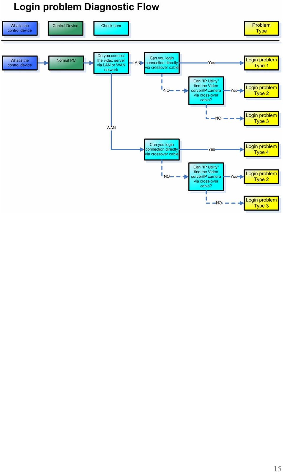
16 Chapter. 4. Login Problem In this Chapter, we will focus the problem that you can t login the Video server. We will provide a diagnostic flow for customer to find out his problem type within this problem category. Then we will examine the possible cause for each problem type and find out the root cause and respective solutions. 4-1 Find out the possible cause Please refer to the diagnostic flow to find out the problem type of the Login Problem. Then you can refer to next section for advanced clarification and troubleshooting. Check Item Remark Step1 Step2 Step3 Check the Control Device Connect the PC directly to the Video server/transcoder then via cross-over cable. Then input the Video server/transcoder to see if you can connect? Refer to the section of each problem type to do root cause clarification and find respective solutions. Please connect to LAN or WAN you used to connect previously 14

17 15
18 4-2 Login Problem Type 1 Refer to the cause clarification and respective solutions of each problem type below. RED circled parts below indicating which building block might cause this problem. Monitor Imaging Management Management Storage Network Network block The possible causes could be as below Inappropriate network infrastructure Because you can connect to the video server/ip camera via cross-over cable but you can t connect it via your LAN environment, your network layout of your LAN might be wrong. Clarification: 16

19 1. Connect the PC and Video Server back to original LAN 2. Use the PC to ping the Video Server s IP address 3. The ping is likely to fail. Solution: 1. Contact your MIS or anyone that build your network infrastructure. 2. Give him the test report above and ask him to fix the ping fail problem If problem not solved, how to report this problem? If the solution above can t solve the problem, please gather the following information and contact our sales. (Please see introduction about how to contact) Problem feedback table Problem feedback table of login problem 1 Category Sub-category Description Product model Model number Firmware Firmware version Video Server Use it to connect? LAN IP setting IP address Submask Gateway Video Server Use it to connect? WAN IP setting IP address Submask Gateway PC IP setting Use it to connect? IP address Submask Gateway Network Network diagram deployment Respective setting of switch / routers. 17

20 4-3 Login Problem Type 2 Refer to the cause clarification and respective solutions of each problem type below. RED circled parts below indicating which building block might cause this problem. Monitor Imaging Management Management Storage Network Network block The possible causes could be as below Inappropriate Video server/ip camera IP address setting Sometimes you can t link to the video server /IP camera It could be caused by the video server/ip camera IP address. This setting is relevant to PC s IP address and Subnet mask setting. Then we will discuss both of them in this section. 18

21 Clarification: 1. Connect the Video Server/IP camera via cross-over cable. 2. Open IP utility and click Refresh to search for the Video Server/IP and PC s IP address. (IP utility should be version later than ). 3. Check the PC s IP setting as below 4. Fill in the table below Video Server/IP PC camera IP address A1.B1.C1.D1 A2.B2.C2.D2 Subnet Mask E1.F1.G1.H1 E2.F2.G2.H2 5. Check according to the check item and see if it follows the rule below. Video Server/IP PC camera Setting A1.B1.C1.D1 A2.B2.C2.D2 IP address Rule to A1=A2, 19
22 Subnet Mask Rule to check B1=B2, C1=C2, D1 D2 Setting E1.F1.G1.H1 Check E1=E2=255, F1=F2=255, G1=G2=255, H1=H2=0 E2.F2.G2.H2 6. If yes, this is not IP address setting. 7. If not, please follow the solution as below. Solution: 1. Follow the rule below to change the PC setting. IP address Video Server/IP camera Setting A1.B1.C1.D1 Rule to check Subnet Mask Rule to A1=A2, B1=B2, C1=C2, D1 D2 Setting E1.F1.G1.H1 Check E1=E2=255, F1=F2=255, G1=G2=255, H1=H2=0 PC A2.B2.C2.D2 E2.F2.G2.H2 2. After change the PC setting, try connecting to the video server/ip camera again Wrong PC IP address setting This site is included in the previous section Please go there and see details. 20
23 Inappropriate Video server/ip camera network port setting It could be caused by the video server/ip camera network port setting. Different network ports are for different functions. Clarification: 1. Connect the Video Server/IP camera via cross-over cable. 2. Open IP utility and click Refresh to search for the Video Server/IP. (IP utility should be version later than ). 3. Find the HTTP port of the video server/ip camera 4. Check if your login link follows the rule below HTTP port Login link Correct? 80 or ports other than 80 (XX= the port setting you find above) Note: is the IP address of the IP camera 5. If yes, this is not port setting issue 6. If not, this is the port setting issue. Solution: 1. Change the login link following the rules below. HTTP port Login link Correct? 80 or ports other than 80 (XX= the port setting you find above) 21
24 4-3-2 Monitoring block The possible causes could be as below Inappropriate O/S and Browser software The possible cause might be the browser software you use to login the video server/ip camera. Clarification: 1. Check if your software Software Recommended version Correct? O/S (Operating software) Windows 2000 SP2 or Window XP Browser Internet Explorer 6.0 and above 2. If they are correct, then it s not software problem 3. If they are not correct, it might be software problem Solution: 1. Please install and use the software recommended Wrong ID and password The login might fail if you input the wrong account ID and password. Clarification: 1. ID and password is captive sensitive, please make sure that you are inputting the right one. Default ID: Admin (captive sensitive) Default Password: Solution: 1. If you can t recall the ID and password, please Hardware reset the camera. (See respective hardware user manual). 2. Then login with the default ID and password Default ID: Admin (captive sensitive) Default Password:
25 4-3-3 If problem not solved, how to report this problem? If the solution above can t solve the problem, please gather the following information and contact our sales. (Please see introduction about how to contact) Problem feedback table Problem feedback table of login problem 1 Category Sub-category Description Product model Firmware Other information you found during the testing Model number Firmware version 23
26 4-4 Login Problem Type 3 Refer to the cause clarification and respective solutions of each problem type below. RED circled parts below indicating which building block might cause this problem. Monitor Imaging Management Management Storage Network Imaging block The possible causes could be as below Inappropriate network physical connection It might because of the physical connection error (such as network cable fail, or cabling wrong). Clarification: 1. Connect your Video server/ip camera to a switch via the network cable you are using. 24
27 2. Check if the Network LED on Video Server and Switch on? 3. If both are on, then is it not physical connection problem 4. If any of those are not, the physical connection is wrong. Solution: 1. If the Video Server/IP camera is using standard RJ-45 network connector, just replace with a new cable. 2. If the Video Server/IP camera is not using standard RJ-45 connector (ex: CAM-5130/CAM-5140/CAM-5150), please use follow the user manual of CAM-5130/CAM-5140/CAM-5150 and make new cable if necessary? Inappropriate network platform temporally failure The network platform very rarely might fail for unknown reason. Clarification: 1. Please reboot the camera. 2. Check if you can find the camera afterward. 3. If yes, this is a network platform temporally failure problem 4. If not, this is not a network platform temporally failure problem Solution: 1. Because the network platform is very rarely to fail, you can go on use it. But if your system temporally fails too often, please contact our sales If problem not solved, how to report this problem? If the solution above can t solve the problem, please gather the following information and contact our sales. (Please see introduction about how to contact). 25
28 Problem feedback table Problem feedback table of login problem 1 Category Sub-category Description Product model Model number Other information you found during the testing 26
29 4-5 Login Problem Type 4 Refer to the cause clarification and respective solutions of each problem type below. RED circled parts below indicating which building block might cause this problem. Monitor Imaging Management Management Storage Network Network block The possible causes could be as below Inappropriate Video server/ip camera network port forwarding setting The problem could be the inappropriate network transmission. Network transmission involves correct setting below 27
30 Network transmission check table Category Video Server Sub-category Internet connectivity Port setting Network Port forwarding Firewall setting PC Internet connectivity Because each parts are dependent to each other. Then we put them all together in this section. Clarification: 1. Please read the support package TS attached. - Chapter 1~3: How does internet communication works - Appendix C : How to check the network communication 2. If the check fails, this is a network communication problem. 3. If the check ok, this is not a network communication problem. Solution: 1. Follows the support package TS to build up the internet communication step by step Inappropriate network port setting The problem is discussed in , please go there for details Video server/ip camera has no internet connectivity The problem is discussed in , please go there for details. 28
31 Blocked by firewall The problem is discussed in , please go there for details PC has no internet connectivity The problem is discussed in , please go there for details If problem not solved, how to report this problem? If the solution above can t solve the problem, please gather the following information and contact our sales. (Please see introduction about how to contact) Problem feedback table Problem feedback table of login problem 1 Category Sub-category Description Product model Firmware Video Server LAN IP setting Video Server WAN IP setting PC IP setting Network deployment Model number Firmware version Use it to connect? IP address Submask Gateway Use it to connect? IP address Submask Gateway Use it to connect? IP address Submask Gateway Network diagram Respective setting of switch / routers. 29
32 30
33 Chapter. 5. Monitor Problem In this Chapter, we will focus the problem that you 1. Can login the video server/ip camera 2. Can t monitor the images we will provide a diagnostic flow for customer to find out his problem type within this problem category. Then we will examine the possible cause for each problem type and find out the root cause and respective solutions. 5-1 Find out the possible cause Please refer to the diagnostic flow to find out the problem type of the Login Problem. Then you can refer to next section for advanced clarification and troubleshooting. Check Item Remark Step1 Step2 Step3 Step4 Check the Control Device Check if you see the Video server/transcoder s analog output on a TV monitor. Connect the PC directly to the Video server/transcoder then via cross-over cable. Then input the Video server/transcoder IP. Refer to the section of each problem type to do root cause clarification and find respective solutions. 31
34 32
35 5-2 Monitor Problem Type 1 Refer to the cause clarification and respective solutions of each problem type below. RED circled parts below indicating which building block might cause this problem. Monitor Imaging Management Management Storage Network Network block The possible causes could be as below Inappropriate network infrastructure (if you were connecting via LAN) The problem could be the inappropriate network infrastructure. Clarification: 33
36 1. Below is the status of this problem definition so far. Function Network environment Respective network ports Cross-over LAN Port name Port number (Default) Login Yes Yes HTTP 80 View image Yes No HTTP 80 Register 6000 Streaming As you can see from the table, there s something wrong about your LAN. Solution: 1. Because this problem involves mostly about your LAN environment, it s less possible for us to provide the solution. 2. Please fill in your definition table Function Network environment Respective network ports Cross-over LAN Port name Port number Login Yes Yes HTTP View image Yes No HTTP Register Streaming 3. Please provide the definition table above to your MIS or your network architect for this problem. Ask him for solution. 34
37 Inappropriate network port forwarding (if you were connecting via WAN) The problem could be the inappropriate network transmission. Network transmission involves correct setting below. Then we put them all together. Network transmission check table Category Video Server Sub-category Internet connectivity Port setting Network Port forwarding Firewall setting PC Internet connectivity Clarification: 1. Below is the status of this problem definition so far. Function Network environment Respective network ports Cross-over WAN Port name Port number (Default) Login Yes Yes HTTP 80 Monitor Yes No HTTP 80 Register 6000 Streaming As you can see from the table, there s something wrong about your WAN. 4. Please read the support package TS attached. - Chapter 1~3: How does internet communication works - Appendix C : How to check the network communication for Monitoring images 5. If the check fails, this is a network communication problem. 6. If the check ok, this is not a network communication 35
38 problem. Solution: 2. Follows the support package TS to build up the internet communication step by step Blocked by firewall (if you were connecting via WAN) The problem is discussed in , please go there for details DNS problem (if you were connecting via DNS) This problem could happen if you connect to the video server/ip camera using Domain Name (Ex: instead of IP address (Ex: Clarification: 1. Please switch the software setting from IP address from Domain Name to IP address and see if you can monitor the images. 2. If yes, this is a DNS problem. 3. If not, this is not a DNS problem. Solution: 1. Report the following information to our sales. We will provide you an updated version A.S.A.P. Category Description Example: Hardware SED-2120 Model number Firmware A1D-V version Software model NVR Software version V Before you get that updated version, you can use IP address instead of Domain name to connect to the video 36
39 server/ip camera and a contingency plan If problem not solved, how to report this problem? If the solution above can t solve the problem, please gather the following information and contact our sales. (Please see introduction about how to contact) Problem feedback table Problem feedback table of login problem 1 Category Sub-category Description Product model Firmware Video Server LAN IP setting Video Server WAN IP setting PC IP setting Network deployment Software Model number Firmware version Use it to connect? IP address Submask Gateway Use it to connect? IP address Submask Gateway Use it to connect? IP address Submask Gateway Network diagram Respective setting of switch / routers. Model Version Setting 37
40 5-3 Monitor Problem Type 2 Refer to the cause clarification and respective solutions of each problem type below. RED circled parts below indicating which building block might cause this problem. Monitor Imaging Management Management Storage Network Monitor block The possible causes could be as below Inappropriate O/S and Browser software The possible cause might be the browser software you use to login the video server/ip camera. Clarification: 1. Check if your software 38
41 Software Recommended version Correct? O/S (Operating software) Windows 2000 SP2 or Windows XP Browser Internet Explorer 6.0 and above 2. If they are correct, then it s not software problem 3. If they are not correct, it might be software problem Solution: 1. Please install and use the software recommended ActiveX control not installed This problem could be caused if you didn t install the ActiveX control. Clarification: 1. Login the web-configurator of video server/ip camera 2. Click the Live Display 3. Check if you see an error sign at the bottom left corner of the web-page. 4. If yes, this is an ActiveX control installation problem 5. If not, this is not an ActiveX control installation problem Solution: 1. Please login this computer as an administrator. (Sometimes only Administrator can install ActiveX) 2. For some models, you can install the ActiveX directly from the video server/ip camera., just click to allow your PC to install the ActiveX control 3. If you still can t install the AcitveX control, please install the ActiveX control installer. (You can always get it from ual/activex%20control/) 39
42 5-3-2 If problem not solved, how to report this problem? If the solution above can t solve the problem, please gather the following information and contact our sales. (Please see introduction about how to contact) Problem feedback table Problem feedback table of login problem 1 Category Sub-category Description Product model Firmware Video Server LAN IP setting Video Server WAN IP setting PC IP setting Network deployment Other information during this troubleshooting Model number Firmware version Use it to connect? IP address Submask Gateway Use it to connect? IP address Submask Gateway Use it to connect? IP address Submask Gateway Network diagram Respective setting of switch / routers. 40
43 5-4 Monitor Problem Type 3 Refer to the cause clarification and respective solutions of each problem type below. RED circled parts below indicating which building block might cause this problem. Monitor Imaging Management Management Storage Network Image The possible causes could be as below Analog Video- Lens problem This could be the lens problem that caused no lighting income to the camera. This problem happens on BOX camera which requires you to install a lens onto it. 41
44 Clarification: 1. Remove the lens 2. See if the image become white 3. If yes, this is the lens problem 4. If not, this is not the lens problem Solution: 1. The solution varies for different kind of lens you use. Please follow the table below for solutions. Lens type Solution steps Auto-Iris Fixed Iris 1 Check if there s anything blocking the lens (ex: lens cover) 2 Be sure to connect the Auto Iris Cable to the camera 3 Be sure to switch the camera setting to Auto Iris or DC Iris 1 Check if there s anything blocking the lens (ex: lens cover) 2 Be sure to switch the camera setting to AES Analog Video- Camera power up fail This could be the camera power up fail. Clarification: The clarification procedure different for different kinds of camera, please see below table for details. Camera Type Clarification procedure Zoom Lens camera 1. Reboot the camera 2. See if the zoom lens moves during start-up (It moves as if it wants to zoom-in then zoom-out) 3. If yes, this is a temporally camera power up problem 42
45 4. If not, this is the a camera power up problem Speed dome or PTZ camera 1. Reboot the camera 2. See if the camera initialize during start-up (it will pan, tilt and zoom) 3. If yes, this is a temporally camera power up problem 4. If not, this is a camera power up problem Other cameras (Not zoom lens or speed dome or PTZ camera) 1. Reboot the camera 2. See if the image becomes ok 3. If yes, this is a temporally camera power up problem 4. If not, this might be a camera power up problem. Please check other possible cause first. If you can t find other possible cause, then we can think it as a camera power up problem. Solution: 1. The solution varies for different kind situation. Please see the table below for respective solutions. Power up problem Solution steps type Temporally power up problem 1 Normally, this problem happens rarely. You can just ignore this problem. 2 If the problem happens very often, please gather problem information and contact our sales. Power up problem 1 If the problem happens very often, please gather problem information and contact our sales Analog Video- BNC wiring fail It happens only when you are using a video server connecting to an analog camera. This could be the camera s BNC wiring fail that 43
46 causes the video server receive no video signal Clarification: 1. Get a BNC cable from a working system (a BNC cable that works fine) 2. Connect the Video server to the IP camera via the BNC cable and see if you can see the image via analog output 3. If yes, this is the BNC wiring problem. 4. If not, this is not the BNC wiring problem Solution: 1. Simply replace current BNC cable with a working one Analog Video- DC level adjust It happens for IP camera or analog camera with DC level adjusts. If the DC level is set to very low, the image will be completely dark. That is because the DC level directly affects the brightness of the camera. Clarification: 1. Increase the DC level according to the hardware manual 2. See if the images is ok 3. If yes, this is DC level problem 4. If not, this is not DC level problem Solution: 1. Adjust the DC level according to your environment.. 44
47 5-4-2 If problem not solved, how to report this problem? If the solution above can t solve the problem, please gather the following information and contact our sales. (Please see introduction about how to contact) Problem feedback table Problem feedback table of login problem 1 Category Sub-category Description Product model Firmware Camera Setting Other information during this troubleshooting Model number Firmware version DC level Auto Iris or AES 45
48 5-5 Monitor Problem Type 4 Refer to the cause clarification and respective solutions of each problem type below. RED circled parts below indicating which building block might cause this problem. Monitor Imaging Management Management Storage Network Network block The possible causes could be as below Inappropriate network port setup The network port setting of the video server/ip camera should be the same as the configuration in Streaming Activator, otherwise, there might be no images coming out. 46
49 Clarification: 1. Login the camera and open streaming Activator to fill in the port setting table below. Function Port Function Video Server/IP camera Streaming Activator Default value Monitor HTTP 80 Register 6000 Streaming Check each function port and see if it is the same in both video server/ip camera and the Streaming Activator (below is a reference result) Function Port Function Video Server/IP camera Streaming Activator The same? Monitor HTTP Yes Register NO Streaming NO 3. If any of those are not the same, this is a port setting problem. 4. If all these port setting are the same, this is not a port setting problem. Solution: 1. Adjust the setting of the streaming activator or video server/ip camera to make the port setting is the same for each port. Example: Function Port Function Video Server/IP camera Streaming Activator The same? Monitor HTTP Yes Register Yes 47
50 ->6000 Streaming >6002 Yes Management block The possible causes could be as below Inappropriate Streaming Activator version For some previous Streaming Activator version, it doesn t support all our IP cameras. Then it could cause the monitor to fail. Clarification: 1. Check the table below to see if it is a Streaming Activator version problem Streaming Activator version Video Server/IP camera Protocol version* TCP1.0* TCP2.0* Version before OK OK Fail Fail Version after OK OK OK OK Note: Please refer to the support package TS Firmware function comparison table of TCP1.0 and TCP2.0 - TCP2.0 and TCP1.0 supporting product list. Note: For TCP1.0 and TCP2.0, please also make sure the firmware version as below - TCP1.0 : The firmware function should be after TCP2.0 : The firmware and TCP1.0 supporting product list. 2. If your using environment is in the grey area above, this is a Streaming Activator version problem. 48
51 Solution: 1. Please go to our website to download the newest Streaming Activator software If problem not solved, how to report this problem? If the solution above can t solve the problem, please gather the following information and contact our sales. (Please see introduction about how to contact) Problem feedback table Problem feedback table of login problem 1 Category Sub-category Description Hard model Firmware Model number Firmware version Software model Use it to connect? Software version Video Server LAN IP setting Video Server WAN IP setting PC IP setting Use it to connect? IP address Submask Gateway Use it to connect? IP address Submask Gateway Use it to connect? IP address Submask Gateway 49
52 5-6 Monitor Problem Type 5 Refer to the cause clarification and respective solutions of each problem type below. RED circled parts below indicating which building block might cause this problem. Monitor Imaging Management Management Storage Network Network block The possible causes could be as below Inappropriate network port setup The network port setting of the video server/ip camera should be the same as the configuration in Streaming Activator, otherwise, there might be no images coming out. Clarification: 1. Login the camera and open streaming Activator to fill in 50
53 the port setting table below. Function Port Function Video Server/IP camera Streaming Activator Default value Monitor HTTP 80 Register 6000 Streaming Check each function port and see if it is the same in both video server/ip camera and the Streaming Activator (below is a reference result) Function Port Function Video Server/IP camera Streaming Activator The same? Monitor HTTP Yes Register NO Streaming NO 3. If any of those are not the same, this is a port setting problem. 4. If all these port setting are the same, this is not a port setting problem. Solution: 1. Adjust the setting of the streaming activator or video server/ip camera to make the port setting is the same for each port. Example: Function Port Function Video Server/IP camera Streaming Activator The same? Monitor HTTP Yes Register >6000 Yes Streaming Yes 51
54 -> Monitor block The possible causes could be as below Inappropriate Streaming Explorer version For some previous Streaming Explorer version, it doesn t support all our IP cameras. Then it could cause the monitor to fail. Clarification: 1. Check the table below to see if it is a Streaming Explorer version problem Streaming Activator version Video Server/IP camera Protocol version* TCP1.0* TCP2.0* Version before 1.0 OK OK Fail Fail Version after 1.1 OK OK OK OK Note: Please refer to the support package TS Firmware function comparison table of TCP1.0 and TCP2.0 - TCP2.0 and TCP1.0 supporting product list. Note: For TCP1.0 and TCP2.0, please also make sure the firmware version as below - TCP1.0 : The firmware function should be after TCP2.0: The firmware and TCP1.0 supporting product list. 2. If your using environment is in the grey area above, this is a Streaming Explorer version problem. Solution: 1. Please go to our website to download the newest 52
55 Streaming Activator software If problem not solved, how to report this problem? If the solution above can t solve the problem, please gather the following information and contact our sales. (Please see introduction about how to contact) Problem feedback table Problem feedback table of login problem 1 Category Sub-category Description Hard model Firmware Model number Firmware version Software model Use it to connect? Software version Video Server LAN IP setting Video Server WAN IP setting PC IP setting Use it to connect? IP address Submask Gateway Use it to connect? IP address Submask Gateway Use it to connect? IP address Submask Gateway 53
56 5-7 Monitor Problem Type 6 Refer to the cause clarification and respective solutions of each problem type below. RED circled parts below indicating which building block might cause this problem. Monitor Imaging Management Management Storage Network Network block The possible causes could be as below Inappropriate network port setup The network port setting of the video server/ip camera should be the same as the configuration in Streaming Activator, otherwise, there might be no images coming out. Clarification: 1. Login the camera and open streaming Activator to fill in 54
57 the port setting table below. Function Port Function Video Server/IP camera Streaming Activator Default value Monitor HTTP 80 Register 6000 Streaming Check each function port and see if it is the same in both video server/ip camera and the Streaming Activator (below is a reference result) Function Port Function Video Server/IP camera Streaming Activator The same? Monitor HTTP Yes Register NO Streaming NO 3. If any of those are not the same, this is a port setting problem. 4. If all these port setting are the same, this is not a port setting problem. Solution: 1. Adjust the setting of the streaming activator or video server/ip camera to make the port setting is the same for each port. Example: Function Port Function Video Server/IP camera Streaming Activator The same? Monitor HTTP Yes Register >6000 Yes Streaming Yes 55
58 -> If problem not solved, how to report this problem? If the solution above can t solve the problem, please gather the following information and contact our sales. (Please see introduction about how to contact) Problem feedback table Problem feedback table of login problem 1 Category Sub-category Description Hard model Firmware Model number Firmware version Software model Use it to connect? Software version Video Server LAN IP setting Video Server WAN IP setting PC IP setting Use it to connect? IP address Submask Gateway Use it to connect? IP address Submask Gateway Use it to connect? IP address Submask Gateway 56
59 Chapter. 6. PTZ Problem In this Chapter, we will focus the problem that you can 1. Can login the video server/ip camera 2. Can monitor the image 3. Can t control camera s PTZ function. We will provide a diagnostic flow for customer to find out his problem type within this problem category. Then we will examine the possible cause for each problem type and find out the root cause and respective solutions. 6-1 Find out the possible cause Please refer to the diagnostic flow to find out the problem type of the Login Problem. Then you can refer to next section for advanced clarification and troubleshooting. Check Item Remark Step1 Step2 Step3 Step4 Check the Control Device Check if you can control the PTZ the Video server/transcoder s analog output on a TV monitor. Connect the PC directly to the Video server/transcoder then via cross-over cable. Then input the Video server/transcoder IP. Refer to the section of each problem type to do root cause clarification and find respective solutions. 57
60 58
61 6-2 PTZ problem Type 1 Refer to the cause clarification and respective solutions of each problem type below. RED circled parts below indicating which building block might cause this problem. Monitor Imaging Management Management Storage Network Network block The possible causes could be as below Inappropriate network infrastructure (if you were connecting via LAN) The problem could be the inappropriate network infrastructure. Clarification: 1. Below is the status of this problem definition so far. 59
62 Function Network environment Respective network ports Cross-over LAN Port name Port number (Default) Login Yes Yes HTTP 80 View image Yes Yes HTTP 80 Register 6000 Streaming 6002 PTZ control Yes No Control As you can see from the table, there s something wrong about your LAN. Solution: 1. Because this problem involves mostly about your LAN environment, it s less possible for us to provide the solution. 2. Please fill in your definition table Function Network environment Respective network ports Cross-over LAN Port name Port number Login Yes Yes HTTP View image Yes Yes HTTP Register Streaming PTZ control Yes No Control 3. Please provide the definition table above to your MIS or your network architect for this problem. Ask him for solution. 60
63 Inappropriate network port forwarding (if you were connecting via WAN) The problem could be the inappropriate network transmission. Network transmission involves correct setting below. Then we put them all together. Network transmission check table Category Video Server Sub-category Internet connectivity Port setting Network Port forwarding Firewall setting PC Internet connectivity Clarification: 1. Below is the status of this problem definition so far. Function Network environment Respective network ports Cross-over WAN Port name Port number (Default) Login Yes Yes HTTP 80 Monitor Yes Yes HTTP 80 Register 6000 Streaming 6002 PTZ Yes No Control As you can see from the table, there s something wrong about your WAN. 3. Please read the support package TS attached. - Chapter 1~3: How does internet communication works - Appendix C : How to check the network communication for Monitoring images 4. If the check fails, this is a network communication problem. 61
64 5. If the check ok, this is not a network communication problem. Solution: 1. Follows the support package TS to build up the internet communication step by step Blocked by firewall (if you were connecting via WAN) The problem is discussed in , please go there for details DNS problem (if you were connecting via DNS) This problem could happen if you connect to the video server/ip camera using Domain Name (Ex: instead of IP address (Ex: Clarification: 1. Please switch the software setting from IP address from Domain Name to IP address and see if you can monitor the images. 2. If yes, this is a DNS problem. 3. If not, this is not a DNS problem. Solution: 1. Report the following information to our sales. We will provide you an updated version A.S.A.P. Category Description Example: Hardware SED-2120 Model number Firmware A1D-V version Software model NVR Software version V Before you get that updated version, you can use IP 62
65 address instead of Domain name to connect to the video server/ip camera and a contingency plan If problem not solved, how to report this problem? If the solution above can t solve the problem, please gather the following information and contact our sales. (Please see introduction about how to contact) Problem feedback table Problem feedback table of login problem 1 Category Sub-category Description Product model Firmware Video Server LAN IP setting Video Server WAN IP setting PC IP setting Network deployment Model number Firmware version Use it to connect? IP address Submask Gateway Use it to connect? IP address Submask Gateway Use it to connect? IP address Submask Gateway Network diagram Respective setting of switch / routers. 63
66 6-3 PTZ problem Type 2 Refer to the cause clarification and respective solutions of each problem type below. RED circled parts below indicating which building block might cause this problem. Monitor Imaging Management Management Storage Network Image block The possible causes could be as below Inappropriate Analog video Serial setting (Baud rate, Parity, Bit length, Stop bit) These serial setting (baud rate, parity, stop bit) must be the same for analog video and network platform for PTZ function to work. We will include both sections in this chapter below. 64
67 Clarification: 1. First, we have to check out the serial settings of analog video and control device (Web-configurator). The checkout procedure might be different. Please refer to the table below. Serial Setting No Description Analog Video Control device 1 Analog Camera + Video Server Please refer to analog camera s Please login the web-configurator manual 2 IP PTZ camera with fixed serial setting * Please see table below for Please login the web-configurator information 3 IP PTZ camera with Adjustable serial setting* Please refer to IP camera hardware manual Please login the web-configurator *: Please refer to the table below for how to differentiate the IP PTZ camera and relative settings. IP PTZ camera with fixed serial Analog Video Serial Setting No Model Baud rate Parity Byte length Stop bit 1 CAM None CAM None CAM None 8 1 IP PTZ camera with Adjustable serial Analog Video Serial Setting No Model Baud rate Parity Byte length Stop bit 1 CAM-6100 Adjustable None CAM-6200 Adjustable None CAM-6500 Adjustable None CAM-6600 Adjustable None 8 1 Sample baud rate setting in web-configurator 65
68 2. Then fill in the table below and check out if the settings from Analog Video and Control device are the same for each serial setting. Serial Setting Serial Setting Analog Video Control device The same? Baud rate Parity Byte length Stop bit Sample table Serial Setting Analog Video Serial Setting Control device The same? Baud rate No Parity None None Yes Byte length 8 8 Yes Stop bit 1 1 Yes 3. If all the serial settings are the same in Analog Video and 66
69 Network platform, this is not a Serial Setting issue. 4. If any of the serial settings is not the in Analog Video and Network platform, this is a Serial Setting issue. Solution: 1. Follow the table below to adjust the setting of the Analog Video and Control device and make all the serial settings the same. (for how to adjust each setting, please refer to hardware manual and software manual) Example:.Before Serial Setting Analog Video Serial Setting Control device The same? Baud rate No Parity None None Yes Byte length 8 8 Yes Stop bit 1 1 Yes.After Serial Setting Serial Setting Analog Video Network Platform The same? Baud rate yes Parity None None Yes Byte length 8 8 Yes Stop bit 1 1 Yes Inappropriate Network platform - Serial Setting (Baud rate, Parity, Bit length, Stop bit) The problem is discussed in , please go there for details. 67
70 Inappropriate Analog video - Protocol setting These PTZ settings (Protocol and Camera ID) must be the same for Analog Video and Controlled device for PTZ function to work. We will include both sections in this chapter below. Clarification: 1. First, we have to check out the protocol of analog video and the controlled device (depends on what device you use to control the PTZ) the checkout procedure might be different. Please refer to the table below. No Description Analog Video PTZ setting Control device 1 Analog Camera + Video Server 2 IP PTZ camera with fixed serial setting * 3 IP PTZ camera with Adjustable serial setting* Please refer to analog camera s manual Please see table below for information Please refer to IP camera hardware manual Please go the control device PTZ setup page Please go the control device PTZ setup page Please go the control device PTZ setup page *: Please refer to the table below for how to differentiate the IP PTZ camera and relative settings. IP PTZ camera with fixed PTZ setting No Model Protocol setting Camera ID 1 CAM-5130 Campro_V1 1 2 CAM-5140 Campro_V1 1 3 CAM-5150 Campro_V1 1 IP PTZ camera with Adjustable PTZ setting No Model Protocol setting Camera ID 1 CAM-6100 Adjustable Camera ID (Pelco-P, Adjustable Pelco-D, VCL) (1~255) 2 CAM-6200 Adjustable Camera ID (Pelco-P, Adjustable Pelco-D, Eyeview) (1~255) 3 CAM-6500 Adjustable Camera ID (Pelco-P, Adjustable 68
71 Pelco-D, Dynacolor*) (1~255) 4 CAM-6600 Adjustable Camera ID (Pelco-P, Pelco-D, Dynacolor*) Adjustable (1~255) *: This protocol is marked as DSCP in the hardware manual *: If the control device is Streaming Activator, please go to the page to find its PTZ setting. Please refer to the table below for how to differentiate the IP PTZ camera and relative settings. 2. Then fill in the table below and check out if the settings from Analog Video and Network Platform are the same for each serial setting. PTZ Setting Serial Setting Analog Video Control device The same? Protocol Camera ID Sample table Serial Setting Analog Video Serial Setting Control device The same? 69
72 Protocol Pelco-P Pelco-D No Camera ID 1 1 Yes 3. If all the PTZ settings are the same in Analog Video and Control device, this is not a PTZ Setting issue. 4. If any of the PTZ settings is not the same in Analog Video and Control device, this is a PTZ Setting issue. Solution: 1. Follow the table below to adjust the setting of the Analog Video and Network platform and make all the serial settings the same. Example:.Before Serial Setting Analog Video Serial Setting Control device The same? Protocol Pelco-P Pelco-D No Camera ID 1 1 Yes.After Serial Setting Serial Setting Analog Video Network Platform The same? Protocol Pelco-P Pelco-P No Camera ID 1 1 Yes Inappropriate Analog Video Camera ID setup The problem is discussed in , please go there for details. 70
73 Inappropriate Network platform - Serial type setup (if you are connecting a video server to an analog camera) The serial connection problem (might happen ONLY on video server + analog cameras. If you are not using video servers + analog cameras, please skip this section. The serial connection type and serial physical connection have to be right on both Video server and Analog cameras for PTZ function to work. Thus we put them both. Clarification: 1. Check out the serial connection type of the analog camera and video servers and fill in the table below. Serial Connection type No Description Analog camera Video server 1 RS-485 * Default 2 RS-232 * 3 RS-422 * *: Please refer to the analog camera s hardware manual for its serial connection type. Sample table Serial Connection type No Description Analog camera Video server 1 RS-485 Default 2 RS RS-422 Yes 2. If all the Serial Connection type is the same in Analog Camera and Video server, this is not a Serial Connection type. Then we go on next step to check out serial physical connection. 3. If any of the Serial Connection type is not the same in Analog Camera and Video server, this is a Serial Connection type issue. Please go to solution to solve it 71
74 first. 4. Follow the system diagram below for how does each serial physical connection goes. (You might need to refer to video server and speed dome s hardware manual for it s serial pin details) RS-485: Data+ Data- Data+ Data- RS-232: T+ R+ GND T+ R+ GND 72
75 T+ T- R+ R- T+ T- R+ R- 5. If your connection is the same as above, this is not a serial physical connection problem. 6. If your connection is not the same as above, this is a serial physical connection problem. Serial Connection Type Solution: 1. Refer to the previous table and adjust both connection type to be the same (please follow the video server s hardware manual) Example:.Before No Description Serial Connection type Analog camera Video server 1 RS-485 Default 2 RS RS-422 Yes.After No Description 1 RS-485 Serial Connection type Analog camera Video server 73
76 2 RS RS-422 Yes Yes Serial Physical Connection Solution: 1. Follow the serial physical connection diagram in Clarification Step 4. Then correct them accordingly Inappropriate Network platform - Serial Physical Connection (if you are connecting a video server to an analog camera) The problem is discussed in , please go there for details Network block The possible causes could be as below Inappropriate network port setup The network port setting of the video server/ip camera should be the same as the configuration in Streaming Activator, otherwise, there might be no images coming out. Clarification: 1. Login the camera and open streaming Activator to fill in the port setting table below. Function Port Function Video Server/IP camera Streaming Activator Default value Monitor HTTP 80 Register 6000 Streaming 6002 Control Check each function port and see if it is the same in both video server/ip camera and the Streaming Activator (below is a reference result) 74
77 Function Port Function Video Server/IP camera Streaming Activator The same? Monitor HTTP Yes Register NO Streaming NO 3. If any of those are not the same, this is a port setting problem. 4. If all these port setting are the same, this is not a port setting problem. Solution: 2. Adjust the setting of the streaming activator or video server/ip camera to make the port setting is the same for each port. Example: Function Port Function Video Server/IP camera Streaming Activator The same? Monitor HTTP Yes Register >6000 Yes Streaming Yes -> Management block The possible causes could be as below Inappropriate baud rate, parity, stop bit setting The problem is discussed in , please go there for details Inappropriate PTZ setting (protocol, camera ID). The problem is discussed in , please go there for details. 75
78 6-3-4 If problem not solved, how to report this problem? If the solution above can t solve the problem, please gather the following information and contact our sales. (Please see introduction about how to contact) Problem feedback table Problem feedback table of login problem 1 Category Sub-category Description Hard model Firmware Software model Software version Analog Video Serial setting Model number Firmware version Serial Type Connection diagram Baud rate Byte length, stop bit Network Platform Software PTZ setting HTTP port Streaming port Control port Register port Serial Type Connection diagram Baud rate Byte length, stop bit Software port setting Other details you find during clarification HTTP port Streaming port Control port Register port 76
79 6-4 PTZ problem Type 3 Refer to the cause clarification and respective solutions of each problem type below. RED circled parts below indicating which building block might cause this problem. Monitor Imaging Management Management Storage Network Management block The possible causes could be as below Inappropriate control panel connection The Control panel connection to Streaming Activator PC might be wrong and cause the PTZ control to fail. 77
80 Clarification: 1. Check out the control panel connection type by referring to the hardware manual No Description Serial Connection type 1 RS RS RS Check if the connection between the control panel and the streaming activator PC as below. (please follow the converter manual for how to connect) No Description Connection 1 RS-485 Control panel =>Serial converter (RS-485 to RS-232) => PC com port 2 RS-232 Control panel => PC com port 3 RS-422 Control panel =>Serial converter (RS-422 to RS-232) => PC com port 3. If the connection is right, this is not control panel connection problem. 4. If the connection is not right, this is a control panel connection problem. Solution: 1. Please follow the system diagram above in the problem clarification and modify the connections Inappropriate Panel connection setting setting (Baud rate, Parity, Byte length, Stop bit, Com port setting) These Panel connection settings have to be the same for the control panel and the streaming activator for this function to work. P 78
81 Clarification: 1. First, we have to check out these Panel connection settings of control panel and streaming activator. And fill in the table below. Panel connection settings No Description Control Panel Streaming Activator 1 Baud rate * ** 2 Parity * ** 3 Byte length * ** 4 Stop bit * ** 5 Com port * ** *: Please refer to the hardware manual for details **: Please login the activator to view the settings as below 2. Check if all the setting is the same. Sample table: No Description Panel connection settings Control Panel Streaming Activator The same? 1 Baud rate No 2 Parity No No Yes 3 Byte length 8 8 Yes 4 Stop bit 1 1 Yes 5 Com port 2 2 Yes 79
82 3. If all the settings are the same, this is not a Panel connection settings problem. 4. If any of the settings is not the same, this is a Panel connection setting problem. Solution: 1. Follow the table below to adjust the setting of the Control Panel and Streaming Activator and make all the Panel connection settings. (for how to adjust each setting, please refer to hardware manual and software manual) 80
83 6-5 PTZ problem Type 4 Refer to the cause clarification and respective solutions of each problem type below. RED circled parts below indicating which building block might cause this problem. Monitor Imaging Management Management Storage Network Image block The possible causes could be as below Inappropriate Analog video Serial setting (Baud rate, Parity, Bit length, Stop bit) These serial setting (baud rate, parity, stop bit) must be the same for analog video and network platform for PTZ function to work. We will include both sections in this chapter below. 81
84 Clarification: 1. First, we have to check out the serial settings of analog video and control device (Control Panel). The checkout procedure might be different. Please refer to the table below. Serial Setting No Description Analog Video Control Panel 1 Analog Camera + Video Server Please refer to analog camera s manual Please refer to the control panel hardware manual 2 IP PTZ camera with fixed serial setting * Please see table below for information Please refer to the control panel hardware manual 3 IP PTZ camera with Adjustable serial setting* Please refer to IP camera hardware manual Please refer to the control panel hardware manual *: Please refer to the table below for how to differentiate the IP PTZ camera and relative settings. IP PTZ camera with fixed serial Analog Video Serial Setting No Model Baud rate Parity Byte length Stop bit 1 CAM None CAM None CAM None 8 1 IP PTZ camera with Adjustable serial Analog Video Serial Setting No Model Baud rate Parity Byte length Stop bit 1 CAM-6100 Adjustable None CAM-6200 Adjustable None CAM-6500 Adjustable None CAM-6600 Adjustable None Then fill in the table below and check out if the settings from Analog Video and Control Panel are the same for 82
85 each serial setting. Serial Setting Baud rate Parity Byte length Stop bit Analog Video Serial Setting Control Panel The same? Sample table Serial Setting Analog Video Serial Setting Control Panel The same? Baud rate No Parity None None Yes Byte length 8 8 Yes Stop bit 1 1 Yes 3. If all the serial settings are the same in Analog Video and Control Panel, this is not a Serial Setting issue. 4. If any of the serial settings is not the in Analog Video and Control Panel, this is a Serial Setting issue. Solution: 1. Follow the table below to adjust the setting of the Analog Video and Control Panel and make all the serial settings the same. (for how to adjust each setting, please refer to hardware manual and software manual) Example:.Before Serial Setting Analog Video Serial Setting Control Panel The same? Baud rate No 83
86 Parity None None Yes Byte length 8 8 Yes Stop bit 1 1 Yes.After Serial Setting Analog Video Serial Setting Control Panel The same? Baud rate yes Parity None None Yes Byte length 8 8 Yes Stop bit 1 1 Yes Inappropriate Network platform - Serial Setting (Baud rate, Parity, Bit length, Stop bit) The problem is discussed in , please go there for details Inappropriate Analog video - Protocol setting These PTZ settings (Protocol and Camera ID) must be the same for Analog Video and Controlled device for PTZ function to work. We will include both sections in this chapter below. Clarification: 2. First, we have to check out the protocol of analog video and the controlled device (depends on what device you use to control the PTZ) the checkout procedure might be different. Please refer to the table below. PTZ setting No Description Analog Video Control Panel 1 Analog Camera + Please refer to Please go the Video Server analog camera s control device PTZ manual setup page 2 IP PTZ camera with Please see table Please go the fixed serial setting * below for control device PTZ information setup page 84
87 3 IP PTZ camera with Adjustable serial setting* Please refer to IP camera hardware manual Please go the control device PTZ setup page *: Please refer to the table below for how to differentiate the IP PTZ camera and relative settings. IP PTZ camera with fixed PTZ setting No Model Protocol setting Camera ID 1 CAM-5130 Campro_V1 1 2 CAM-5140 Campro_V1 1 3 CAM-5150 Campro_V1 1 IP PTZ camera with Adjustable PTZ setting No Model Protocol setting Camera ID 1 CAM-6100 Adjustable Camera ID (Pelco-P, Pelco-D, VCL) Adjustable (1~255) 2 CAM-6200 Adjustable Camera ID (Pelco-P, Pelco-D, Eyeview) Adjustable (1~255) 3 CAM-6500 Adjustable Camera ID (Pelco-P, Pelco-D, Dynacolor*) Adjustable (1~255) 4 CAM-6600 Adjustable Camera ID (Pelco-P, Pelco-D, Dynacolor*) Adjustable (1~255) *: This protocol is marked as DSCP in the hardware manual 3. Then fill in the table below and check out if the settings from Analog Video and Network Platform are the same for each serial setting. PTZ Setting Serial Setting Analog Video Control Panel The same? Protocol Camera ID Sample table Serial Setting Analog Video Serial Setting Control Panel The same? 85
88 Protocol Pelco-P Pelco-D No Camera ID 1 1 Yes 5. If all the PTZ settings are the same in Analog Video and Control Panel, this is not a PTZ Setting issue. 6. If any of the PTZ settings is not the same in Analog Video and Control Panel, this is a PTZ Setting issue. Solution: 3. Follow the table below to adjust the setting of the Analog Video and Control Panel and make all the serial settings the same. Example:.Before Serial Setting Analog Video Serial Setting Control Panel The same? Protocol Pelco-P Pelco-D No Camera ID 1 1 Yes.After Serial Setting Analog Video Serial Setting Control Panel The same? Protocol Pelco-P Pelco-P No Camera ID 1 1 Yes Inappropriate Analog Video Camera ID setup The problem is discussed in , please go there for details. 86
89 Inappropriate Network platform - Serial type setup (if you are connecting a video server to an analog camera) The serial connection problem (might happen ONLY on video server + analog cameras. If you are not using video servers + analog cameras, please skip this section. The serial connection type and serial physical connection have to be right on both Video server and Analog cameras for PTZ function to work. Thus we put them both. Clarification: 1. Check out the serial connection type of the analog camera and video servers and fill in the table below. Serial Connection type No Description Analog camera Video server 1 RS-485 * Default 2 RS-232 * 3 RS-422 * *: Please refer to the analog camera s hardware manual for its serial connection type. Sample table Serial Connection type No Description Analog camera Video server 1 RS-485 Default 2 RS RS-422 Yes 2. If all the Serial Connection type is the same in Analog Camera and Video server, this is not a Serial Connection type. Then we go on next step to check out serial physical connection. 3. If any of the Serial Connection type is not the same in Analog Camera and Video server, this is a Serial Connection type issue. Please go to solution to solve it 87
90 first. 4. Follow the system diagram below for how does each serial physical connection goes. (You might need to refer to video server and speed dome s hardware manual for it s serial pin details) RS-485: Data+ Data- Data+ Data- RS-232: T+ R+ GND T+ R+ GND 88
91 RS-422: T+ T- R+ R- T+ T- R+ R- 5. If your connection is the same as above, this is not a serial physical connection problem. 6. If your connection is not the same as above, this is a serial physical connection problem. Serial Connection Type Solution: 2. Refer to the previous table and adjust both connection type to be the same (please follow the video server s hardware manual) Example:.Before No Description Serial Connection type Analog camera Control Panel 1 RS-485 Default 2 RS RS-422 Yes.After No Description Serial Connection type Analog camera Control Panel 89
92 1 RS RS RS-422 Yes Yes Serial Physical Connection Solution: 2. Follow the serial physical connection diagram in Clarification Step 4. Then correct them accordingly Inappropriate Network platform - Serial Physical Connection (if you are connecting a video server to an analog camera) The problem is discussed in , please go there for details Management block The possible causes could be as below Inappropriate panel protocol The problem is discussed in , please go there for details Inappropriate panel baud rate, parity, stop bit setup The problem is discussed in , please go there for details Inappropriate panel model number Because there are so many proprietary control panels on the market, sometimes the PTZ fail just because the control panel is not compatible with the video server. Clarification: 1. Check with the IP camera or Analog camera vendor for its compatibility. Or you can test by yourself. Solution: 1. Replace it with the control panel approved by the IP camera or analog camera vendor. 90
93 6-6 PTZ problem Type 5 Refer to the cause clarification and respective solutions of each problem type below. RED circled parts below indicating which building block might cause this problem. Monitor Imaging Management Management Storage Network Image block Refer to the cause clarification and respective solutions of each problem type below. RED circled parts below indicating which building block might cause this problem. 91
94 Monitor Imaging Management Management Storage Network Image block The possible causes could be as below Inappropriate Analog video Serial setting (Baud rate, Parity, Bit length, Stop bit) These serial setting (baud rate, parity, stop bit) must be the same for analog video and network platform for PTZ function to work. We will include both sections in this chapter below. 92
95 Clarification: 1. First, we have to check out the serial settings of analog video and control device (Web-configurator). The checkout procedure might be different. Please refer to the table below. Serial Setting No Description Analog Video Control device 1 Analog Camera + Video Server Please refer to analog camera s Please login the web-configurator manual 2 IP PTZ camera with fixed serial setting * Please see table below for Please login the web-configurator information 3 IP PTZ camera with Adjustable serial setting* Please refer to IP camera hardware manual Please login the web-configurator *: Please refer to the table below for how to differentiate the IP PTZ camera and relative settings. IP PTZ camera with fixed serial Analog Video Serial Setting No Model Baud rate Parity Byte length Stop bit 1 CAM None CAM None CAM None 8 1 IP PTZ camera with Adjustable serial Analog Video Serial Setting No Model Baud rate Parity Byte length Stop bit 1 CAM-6100 Adjustable None CAM-6200 Adjustable None CAM-6500 Adjustable None CAM-6600 Adjustable None 8 1 Sample baud rate setting in web-configurator 93
96 2. Then fill in the table below and check out if the settings from Analog Video and Control device are the same for each serial setting. Serial Setting Serial Setting Analog Video Control device The same? Baud rate Parity Byte length Stop bit Sample table Serial Setting Analog Video Serial Setting Control device The same? Baud rate No Parity None None Yes Byte length 8 8 Yes Stop bit 1 1 Yes 94
97 3. If all the serial settings are the same in Analog Video and Network platform, this is not a Serial Setting issue. 4. If any of the serial settings is not the in Analog Video and Network platform, this is a Serial Setting issue. Solution: 2. Follow the table below to adjust the setting of the Analog Video and Control device and make all the serial settings the same. (for how to adjust each setting, please refer to hardware manual and software manual) Example:.Before Serial Setting Analog Video Serial Setting Control device The same? Baud rate No Parity None None Yes Byte length 8 8 Yes Stop bit 1 1 Yes.After Serial Setting Serial Setting Analog Video Network Platform The same? Baud rate yes Parity None None Yes Byte length 8 8 Yes Stop bit 1 1 Yes Inappropriate Network platform - Serial Setting (Baud rate, Parity, Bit length, Stop bit) The problem is discussed in , please go there for details. 95
98 Inappropriate Analog video - Protocol setting These PTZ settings (Protocol and Camera ID) must be the same for Analog Video and Controlled device for PTZ function to work. We will include both sections in this chapter below. Clarification: 3. First, we have to check out the protocol of analog video and the controlled device (depends on what device you use to control the PTZ) the checkout procedure might be different. Please refer to the table below. No Description Analog Video PTZ setting Control device 1 Analog Camera + Video Server 2 IP PTZ camera with fixed serial setting * 3 IP PTZ camera with Adjustable serial setting* Please refer to analog camera s manual Please see table below for information Please refer to IP camera hardware manual Please go the control device PTZ setup page Please go the control device PTZ setup page Please go the control device PTZ setup page *: Please refer to the table below for how to differentiate the IP PTZ camera and relative settings. IP PTZ camera with fixed PTZ setting No Model Protocol setting Camera ID 1 CAM-5130 Campro_V1 1 2 CAM-5140 Campro_V1 1 3 CAM-5150 Campro_V1 1 IP PTZ camera with Adjustable PTZ setting No Model Protocol setting Camera ID 1 CAM-6100 Adjustable Camera ID (Pelco-P, Adjustable Pelco-D, VCL) (1~255) 2 CAM-6200 Adjustable Camera ID (Pelco-P, Adjustable Pelco-D, Eyeview) (1~255) 96
99 3 CAM-6500 Adjustable Camera ID (Pelco-P, Pelco-D, Dynacolor*) Adjustable (1~255) 4 CAM-6600 Adjustable Camera ID (Pelco-P, Pelco-D, Dynacolor*) Adjustable (1~255) *: This protocol is marked as DSCP in the hardware manual *: If the control device is Streaming Activator, please go to the page to find its PTZ setting. Please refer to the table below for how to differentiate the IP PTZ camera and relative settings. 4. Then fill in the table below and check out if the settings from Analog Video and Network Platform are the same for each serial setting. PTZ Setting Serial Setting Analog Video Control device The same? Protocol Camera ID Sample table Serial Setting Serial Setting The same? 97
100 Analog Video Control device Protocol Pelco-P Pelco-D No Camera ID 1 1 Yes 7. If all the PTZ settings are the same in Analog Video and Control device, this is not a PTZ Setting issue. 8. If any of the PTZ settings is not the same in Analog Video and Control device, this is a PTZ Setting issue. Solution: 4. Follow the table below to adjust the setting of the Analog Video and Network platform and make all the serial settings the same. Example:.Before Serial Setting Analog Video Serial Setting Control device The same? Protocol Pelco-P Pelco-D No Camera ID 1 1 Yes.After Serial Setting Serial Setting Analog Video Network Platform The same? Protocol Pelco-P Pelco-P No Camera ID 1 1 Yes Inappropriate Analog Video Camera ID setup The problem is discussed in , please go there for details. 98
101 Inappropriate Network platform - Serial type setup (if you are connecting a video server to an analog camera) The serial connection problem (might happen ONLY on video server + analog cameras. If you are not using video servers + analog cameras, please skip this section. The serial connection type and serial physical connection have to be right on both Video server and Analog cameras for PTZ function to work. Thus we put them both. Clarification: 2. Check out the serial connection type of the analog camera and video servers and fill in the table below. Serial Connection type No Description Analog camera Video server 1 RS-485 * Default 2 RS-232 * 3 RS-422 * *: Please refer to the analog camera s hardware manual for its serial connection type. Sample table Serial Connection type No Description Analog camera Video server 1 RS-485 Default 2 RS RS-422 Yes 7. If all the Serial Connection type is the same in Analog Camera and Video server, this is not a Serial Connection type. Then we go on next step to check out serial physical connection. 8. If any of the Serial Connection type is not the same in Analog Camera and Video server, this is a Serial Connection type issue. Please go to solution to solve it 99
102 first. 9. Follow the system diagram below for how does each serial physical connection goes. (You might need to refer to video server and speed dome s hardware manual for it s serial pin details) RS-485: Data+ Data- Data+ Data- RS-232: T+ R+ GND T+ R+ GND 100
103 T+ T- R+ R- T+ T- R+ R- 10. If your connection is the same as above, this is not a serial physical connection problem. 11. If your connection is not the same as above, this is a serial physical connection problem. Serial Connection Type Solution: 3. Refer to the previous table and adjust both connection type to be the same (please follow the video server s hardware manual) Example:.Before No Description Serial Connection type Analog camera Video server 1 RS-485 Default 2 RS RS-422 Yes.After No Description 1 RS-485 Serial Connection type Analog camera Video server 101
104 2 RS RS-422 Yes Yes Serial Physical Connection Solution: 3. Follow the serial physical connection diagram in Clarification Step 4. Then correct them accordingly Inappropriate Network platform - Serial Physical Connection (if you are connecting a video server to an analog camera) The problem is discussed in , please go there for details Network block The possible causes could be as below Inappropriate network port setup The network port setting of the video server/ip camera should be the same as the configuration in Streaming Activator, otherwise, there might be no images coming out. Clarification: 5. Login the camera and open streaming Activator to fill in the port setting table below. Function Port Function Video Server/IP camera Streaming Activator Default value Monitor HTTP 80 Register 6000 Streaming 6002 Control Check each function port and see if it is the same in both video server/ip camera and the Streaming Activator (below is a reference result) 102
105 Function Port Function Video Server/IP camera Streaming Activator The same? Monitor HTTP Yes Register NO Streaming NO 7. If any of those are not the same, this is a port setting problem. 8. If all these port setting are the same, this is not a port setting problem. Solution: 5. Adjust the setting of the streaming activator or video server/ip camera to make the port setting is the same for each port. Example: Function Port Function Video Server/IP camera Streaming Activator The same? Monitor HTTP Yes Register >6000 Yes Streaming Yes -> Management block The possible causes could be as below Inappropriate baud rate, parity, stop bit setting The problem is discussed in , please go there for details Inappropriate PTZ setting (protocol, camera ID). The problem is discussed in , please go there for details. 103
106 6-6-5 If problem not solved, how to report this problem? If the solution above can t solve the problem, please gather the following information and contact our sales. (Please see introduction about how to contact) Problem feedback table Problem feedback table of login problem 1 Category Sub-category Description Hard model Firmware Software model Software version Analog Video Serial setting Model number Firmware version Serial Type Connection diagram Baud rate Byte length, stop bit Network Platform Software PTZ setting HTTP port Streaming port Control port Register port Serial Type Connection diagram Baud rate Byte length, stop bit Software port setting Other details you find during clarification HTTP port Streaming port Control port Register port 104
107 Chapter. 7. Video Quality Problem In this Chapter, we will focus the problem that you can 1. Can login the video server/ip camera 2. Can monitor the image 3. Video Quality is not good. We will provide a diagnostic flow for customer to find out his problem type within this problem category. Then we will examine the possible cause for each problem type and find out the root cause and respective solutions. 7-1 Find out the possible cause Please refer to the diagnostic flow to find out the problem type of the Login Problem. Then you can refer to next section for advanced clarification and troubleshooting. Check Item Remark Step1 Check the Control Device Step2 Step3 Step4 What is your video quality problem type? 1. Image color is not true 2. Image blur 3. Image flashing Do you find the same problem on a TV connecting to the analog output? Refer to the section of each problem type to do root cause clarification and find respective solutions. Please make sure the TV color display is ok 105
108 106
109 7-2 Video Quality problem Type 1 Refer to the cause clarification and respective solutions of each problem type below. RED circled parts below indicating which building block might cause this problem. Monitor Imaging Management Management Storage Network Image block The possible causes could be as below Inappropriate Network Platform Video parameter The in-correct image color might be resulted in-correct Video Parameter setup in the network platform. This will result in in-correct color rendering during image compression. 107
110 Clarification: 1. Login the video server/ip camera to check out its video parameter and fill in the table as below. 2. Fill them in the video parameter table below. The table below is divided by two parameter a. Monitor type b. Video Type of the Camera spec Monitor Type Recommended parameter Video Type NTSC PAL Hue Brightness Contrast Saturation Your setting (Video server /IP camera) 3. If these video parameters are the same as recommended, this is not a network platform video parameter problem 4. If any of these video parameters are not the same as 108
111 recommended, this is a network platform video parameter problem. Solution: 1. Adjust the video parameter to make it exactly the same as the one in recommended Inappropriate Analog Video Video Type Sometimes If the analog video output is not right, the in-correct color issue might be caused by in-appropriate Video Type. Clarification: 1. Login the video server/ip camera to check out its video parameter and fill in the table as below. Fill them in the video parameter table below. Monitor Type Your setting Recommended (Video server parameter /IP camera) Video Type NTSC PAL Hue
112 Brightness Contrast Saturation If these video parameters are the same as recommended, this is not a network platform video parameter problem 3. If any of these video parameters are not the same as recommended, this is a network platform video parameter problem. Solution: 1. Adjust the video parameter to make it exactly the same as the one in recommended Management block Block The possible causes could be as below Inappropriate Software Video Parameter setup The in-correct image color might be resulted in-correct Software video Parameter setup in the Streaming Activator. This will result in in-correct color rendering during image compression. Clarification: 1. Open Streaming Activator and go to Camera Setup page. 2. Click Preview to connect to the video server / IP camera and find the video parameter. 110
113 Fill them in the video parameter table below. Monitor Type Recommended Software value setting Video Type NTSC PAL Hue Brightness Contrast Saturation If these video parameters are the same as recommended, this is not a software video parameter problem 4. If any of these software video parameters are not the same as recommended, this is a software video parameter problem Solution: 1. Adjust the software video parameter to make it exactly the same as the one in recommended. 111
114 7-2-3 Other block The possible causes could be as below Inappropriate PC / TV monitor setting The color rendering issue might be caused by incorrect monitor you use. Clarification: 1. Make sure the Video Parameter in Web-configurator is ok first. (Follow the rules in 7-2-1, 7-2-3, 7-2-4) 2. Try to image on this monitor and see if the color is correct? 3. If yes, this is not PC / TV monitor setting issue. 4. If not, this is PC / TV monitor setting issue. Solution: 1. Adjust the video parameter of the PC / TC monitor (following the monitor manual) to make the color right If problem not solved, how to report this problem? If the solution above can t solve the problem, please gather the following information and contact our sales. (Please see introduction about how to contact) Problem feedback table Problem feedback table of login problem 1 Category Sub-category Description Hard model Firmware Model number Firmware version 112
115 Software model Software version Network Platform Video Software Video setting Other details you find during clarification Video Type Hue Brightness Contrast Saturation Video Type Hue Brightness Contrast Saturation 113
116 7-3 Video Quality problem Type 2 Refer to the cause clarification and respective solutions of each problem type below. RED circled parts below indicating which building block might cause this problem. Monitor Imaging Management Management Storage Network Image block The possible causes could be as below Inappropriate Analog video Video Type If the analog video output is not right, the in-correct color issue might be caused by in-appropriate Video Type. Clarification: 114
117 1. Check out your local TV video type (NTSC/PAL) and the IP camera / analog camera s video type (NTSC/PAL) Analog Video Type TV camera/ip The same? camera NTSC PAL 2. Check if the TV video type is the same as the IP camera / analog camera? Example Analog Video Type TV camera/ip The same? camera NTSC PAL No 3. If the video type is the same, this is not an analog video video type problem. 4. If the video type is not the same, this is an analog video video type problem. Solution: 1. Replace the current camera with a right video type camera. Example: Before: Analog Video Type TV camera/ip The same? camera NTSC PAL No 115
118 After: Analog Video Type TV camera/ip The same? camera NTSC PAL No Inappropriate Analog video White balance setting If the analog video output is not right, the in-correct color issue might be caused by in-appropriate analog video white balance setting. Clarification: White balance settings are subject to different environments, and the clarification is done via testing different settings. Before we do that, we have to know what the white balance settings available are. (Some settings might not be available for some cameras) a. AWB (Auto White Balance) b. ATW (Auto Trace White Balance) c. PWB (Push-to-lock White Balance) d. Manually Adjust (Manually set Red and Blue parameters) 1. We will follow the flow below to try different white balance settings. 2. First, if you have AWBs and ATWS settings, please switch between AWB and ATWs and see if the color is 116
119 correct. You can refer to the table for what white balance setting a camera has. (Note: this only includes ACTi IP cameras, for other analog cameras, you have to refer to their hardware manual respectively) Camera Series AWB ATW PWB Manual Adjust CAM-5100 CAM-5200 CAM-5300 CAM-5130 CAM-5140 CAM-5150 CAM-7100 CAM-6100 CAM-6200 CAM-6500 CAM If step2 fail, switch the white balance to PWB and see if the color is correct. Please refer the following procedure for PWB setting. a. Use a white paper to fully cover the camera s lens b. Switch to PWB setting c. Make camera to sync white balance setting with current paper (please see respective hardware manual) d. Remove the white paper e. Check if the color is correct now. 4. If step3 fail, switch the white balance to Manual Adjust for color correction. (please see respective hardware manual) Solution: 117
120 The solution is done during the clarification stage above If problem not solved, how to report this problem? If the solution above can t solve the problem, please gather the following information and contact our sales. (Please see introduction about how to contact) Problem feedback table Problem feedback table of login problem 1 Category Sub-category Description Hard model Firmware Analog Video Other details you find during clarification Model number Firmware version Video Type White balance setting On-site situation 118
121 7-4 Video Quality problem Type 3 Refer to the cause clarification and respective solutions of each problem type below. RED circled parts below indicating which building block might cause this problem. Monitor Imaging Management Management Storage Network Image block The possible causes could be as below Inappropriate Analog Video Focus If the focus is not right, the image is likely to be blurred. Clarification: 1. First, we have to what kind of camera you are using 119
122 2. Then refer to the table below for adjusting the focus and see if the image becomes clear. Camera Type Manually adjust the lens Adjust via software remotely Box / Dome camera * with Fixed lens Box / Dome camera * with varifocal lens Zoom lens camera ** Speed dome camera ** *. Please refer to lens hardware manual for focus adjust **. Please refer to IP camera s hardware manual to adjust the focus. 3. If adjusting the focus doesn t solve this problem, this is not a focus problem. 4. If adjusting the focus solves the problem, please check the table for further action. Camera Type Problem Fixed Adjust OSD setting Box / Dome camera with Fixed lens Box / Dome camera with varifocal lens Zoom lens camera * (go to Step5) Speed dome camera * (go to Step5) 5. This steps is for cameras supporting OSD function a. zoom lens camera b. speed dome camera Please make sure the focus setting in the OSD menu is set to Auto. You can refer to respective hardware manual 120
123 for how to setup. Solution: The solution is done during the clarification stage above Inappropriate Analog Video Lens, CCD, Cover cleanness If the lens, CCD, cover is dirty, the image is likely to be blurred. Clarification: 1. Please check if the items below are clear Item Clean Lens CCD Cover 2. If not clear, please only clean it with special wipers for glass. Item Wiper for Glass Use blower Lens CCD Cover Solution: The solution is done during the clarification stage above Inappropriate Analog Video Lens type (for Box camera with day/night function) This problem is because of the focus shift between the day/night modes of the camera. This problem happens only on camera a. with day/night function 121
124 b. without lens built-in (lens is bought in addition to the camera) please see the table below Day/Night cameras Camera Type Model No. Possible lens type problem Box camera CAM-5120 CAM-5220 CAM-5320 Yes Yes Yes Zoom lens CAM camera CAM Speed dome CAM-6110 CAM-6120 CAM-6220 CAM-6230 CAM-6510 CAM-6520 CAM-6610 CAM Clarification: 1. If you are using the camera above marked with this possible les type problem, then you have to check the lens type you use. Item Focus situation Normal Lens IR correct In either Day / Night situation In switching between Day / Night situation 2. If you are using IR correct lens, this is not an analog video lens type problem. 122
125 3. If you are not using IR correct lens, this is an analog video Lens type problem. Solution: 1. Please purchase the lens with IR correct function to ensure the focus right in switching between Day/Night modes Inappropriate Analog Video OSD setting (for cameras supporting OSD function) This is discussed in Please go there and see details If problem not solved, how to report this problem? If the solution above can t solve the problem, please gather the following information and contact our sales. (Please see introduction about how to contact) Problem feedback table Problem feedback table of login problem 1 Category Sub-category Description Hard model Firmware Analog Video Other details you find during clarification Model number Firmware version Lens type OSD setting (if the camera have) Lens cleanness CCD cleanness Cover cleanness 123
126 7-5 Video Quality problem Type 4 Refer to the cause clarification and respective solutions of each problem type below. RED circled parts below indicating which building block might cause this problem. Monitor Imaging Management Management Storage Network Image block The possible causes could be as below Inappropriate Network Platform Bit rate, frame rate The video quality is determined by 3 parameters a. Resolution b. Bit rate c. frame rate 124
127 Thus, a wrong combination of the 3 parameters is very likely to cause the blurred images. Clarification: 1. Please refer to support package TS about the respective video. Item Focus situation Normal Lens IR correct In either Day / Night situation In switching between Day / Night situation 2. If you are using IR correct lens, this is not an analog video lens type problem. 3. If you are not using IR correct lens, this is an analog video Lens type problem. Solution: 1. Please purchase the lens with IR correct function to ensure the focus right in switching between Day/Night modes If problem not solved, how to report this problem? If the solution above can t solve the problem, please gather the following information and contact our sales. (Please see introduction about how to contact) Problem feedback table Problem feedback table of login problem 1 Category Sub-category Description Hard model Firmware Analog Video Model number Firmware version Resolution 125
128 Other details you find during clarification Frame rate Bit rate 126
129 7-6 Video Quality problem Type 5 Refer to the cause clarification and respective solutions of each problem type below. RED circled parts below indicating which building block might cause this problem. Monitor Imaging Management Management Storage Network Image block The possible causes could be as below Inappropriate Analog Video Video Type The video flash is likely to be caused by inappropriate Video Type. Clarification: 1. Check out your local TV video type (NTSC/PAL) and the IP camera / analog camera s video type (NTSC/PAL) 127
130 Analog Video Type TV camera/ip The same? camera NTSC PAL 2. Check if the TV video type is the same as the IP camera / analog camera? Example Analog Video Type TV camera/ip The same? camera NTSC PAL No 3. If the video type is the same, this is not an analog video video type problem. 4. If the video type is not the same, this is an analog video video type problem. Solution: 1. Replace the current camera with a right video type camera. Example: Before: Analog Video Type TV camera/ip The same? camera NTSC PAL No After: 128
131 Analog Video Type TV camera/ip The same? camera NTSC PAL No If problem not solved, how to report this problem? If the solution above can t solve the problem, please gather the following information and contact our sales. (Please see introduction about how to contact) Problem feedback table Problem feedback table of login problem 1 Category Sub-category Description Hard model Firmware Analog Video Serial setting Environment condition Other details you find during clarification Model number Firmware version Video Type TV video type Electric frequency 129
132 7-7 Video Quality problem Type 6 Refer to the cause clarification and respective solutions of each problem type below. RED circled parts below indicating which building block might cause this problem. Monitor Imaging Management Management Storage Network Image block The possible causes could be as below Inappropriate Analog Video Video Type The video flash is likely to be caused by inappropriate Video Type. Clarification: 1. Check out your local TV video type (NTSC/PAL) and the IP camera / analog camera s video type (NTSC/PAL) 130
133 Analog Video Type TV camera/ip The same? camera NTSC PAL 2. Check if the TV video type is the same as the IP camera / analog camera? Example Analog Video Type TV camera/ip The same? camera NTSC PAL No 3. If the video type is the same, this is not an analog video video type problem. 4. If the video type is not the same, this is an analog video video type problem. Solution: 1. Replace the current camera with a right video type camera. Example: Before: Analog Video Type TV camera/ip The same? camera NTSC PAL No After: 131
134 Analog Video Type TV camera/ip The same? camera NTSC PAL No Inappropriate Analog Video Iris, ES (Electric Shutter) setting Both of the Iris setting and ES setting is used to adapt the camera to current environment lighting conditions. If you use AES (Auto Electric Shutter) it is very likely for you to have the image flashing problem. Please see below for details. Clarification: 1. Check out the setting of your camera to see its iris setting and ES setting. Video Type Auto Fixed Iris Setting ES Note: Mostly, the ES setting will be fixed when Iris setting is set to Auto. 2. Please see if your setting is the same as recommended in the table. (please refer to respective hardware manual for how to setup) Example Recommendation Your setting Video Type Auto Fixed Auto Fixed Iris Setting ES 132
135 3. If the Iris and ES settings are the same, this is not an analog video Iris and ES settings. 4. If the Iris and ES settings are not the same, this is an analog video Iris and ES settings. Solution: 1. Set the Iris and ES setting as recommended. Example: Before: Recommendation Your setting Video Type Auto Fixed Auto Fixed Iris Setting ES After: Video Type Recommendation Your setting Auto Fixed Auto Fixed Iris Setting ES Inappropriate Analog Video Flickerless This problem happens on places where TV video type s frequency is different from the local electric frequency (ex: Japan). If the TV video type s frequency is the same as the local electric frequency, you can skip this section.. Clarification: 1. Check out the TV video type and the electric frequency and find your column in the table. Electric TV Video Type 133
136 Frequency NTSC PAL 50Hz A B 60Hz C D 2. If you are in column B, C, this is not a Flickerless problem 3. If you are in column A, D, this is a Flickerless problem. Solution: 1. Please refer to the table for solution for each camera type in different kind of video type environment. Camera Series NTSC PAL Enable Flickerless Set ES fixed at 1/100sec Enable Flickerless Set ES fixed at 1/120sec Camera CAM-5100 with Flickerless function CAM-5200 CAM-5300 Camera CAM-5130 with CAM-5140 Flickerless CAM-5150 function CAM-7100 CAM-6100 CAM-6200 CAM-6500 CAM
137 7-7-2 If problem not solved, how to report this problem? If the solution above can t solve the problem, please gather the following information and contact our sales. (Please see introduction about how to contact) Problem feedback table Problem feedback table of login problem 1 Category Sub-category Description Hard model Firmware Analog Video Serial setting Environment condition Other details you find during clarification Model number Firmware version Video Type Iris setting ES setting Flickerless setting TV video type Electric frequency Local lighting condition 135
138 7-8 Video Quality problem Type 7 Refer to the cause clarification and respective solutions of each problem type below. RED circled parts below indicating which building block might cause this problem. Monitor Imaging Management Management Storage Network Image block The possible causes could be as below Unknown problem It is rare to see mosaic at the analog output. The possible cause could be CCD or Camera DSP mal-function. Please capture a picture of the analog mosaic images and send it back. 136
139 7-9 Video Quality problem Type 8 Refer to the cause clarification and respective solutions of each problem type below. RED circled parts below indicating which building block might cause this problem. Monitor Imaging Management Management Storage Network Monitor, Management, Storage Block The possible causes could be as below Inappropriate PC specs The mosaic problem might happen if your PC doesn t have enough computing power to decode the image. Clarification: 1. Check out the support package TS to check if you re PC meets the system requirement of our software. 137
140 2. If your system meets the requirement, this is not an inappropriate PC spec problem. 3. If your system fails to meet to requirement, this is an inappropriate PC spec problem. Solution: 1. Please follow the system requirement in support package TS to adjust your PC spec If problem not solved, how to report this problem? If the solution above can t solve the problem, please gather the following information and contact our sales. (Please see introduction about how to contact) Problem feedback table Problem feedback table of login problem 1 Category Sub-category Description Hard model Firmware Software model Software version Network connection PC spec Model number Firmware version Connection (LAN or WAN or cross-over) CPU RAM Motherboard FSB Other details VGA card Register port 138
141 you find during clarification 139
142 7-10 Video Quality problem Type 9 Refer to the cause clarification and respective solutions of each problem type below. RED circled parts below indicating which building block might cause this problem. Monitor Imaging Management Management Storage Network Monitor, Management, Storage block The possible causes could be as below Too many con-current users The mosaic problem might happen if there are too many con-current users connecting to the video server/ip camera and cause it overload. Clarification: 1. Please fill in the table below about the video setting and 140
143 number of con-current users. (If you use one PC to record, and one PC to view the images, there are two con-current user of this video server/ip camera) Item Description Bit rate Protocol Type (TCP1.0 or TCP2.0)* Number of connections * Please refer to the support package TS and your video setting in web-configurator for Protocol type are you using. Example: Item Bit rate Protocol Type (TCP1.0 or TCP2.0) Number of connections Description 3M Refer to the table below to find out the con-current user we support. This table is divided by different combination of bit rate and protocol types. Bit rate Protocol type TCP1.0 TCP2.0 3M M K If your con-current user exceeds the con-current user we supported, this is a problem of too many con-current users. 141
144 4. If your con-current user doesn t exceed the con-current user we supported, this is a problem of too many con-current users. Solution: 1. There are two types of solution to solve this problem. a. Decrease the bit rate to increase the con-current user (Note: Decrease the bit rate might cause the video quality to decrease as well) b. Decrease the number of con-current user. (decrease the number of user by changing system design) Network block The possible causes could be as below Insufficient/instable network bandwidth Insufficient network bandwidth or instable network bandwidth is very likely to cause the network package to be lost during transmission. Too many drop network packages will cause mosaic. Clarification: 1. Because the mosaic disappears when connecting via cross-over cable. The problem definition will be as below Connection Type Mosaic Normal Previous network Cross-over 2. Please bring the test result to your MIS or the one build-up your network infrastructure and ask him to clarify if the network bandwidth is ok and stable. Item Description Bit rate 3M Protocol Type 1 (TCP1.0 or TCP2.0) Number of 2 142
145 connections Connection Type Mosaic Normal Previous network Cross-over 3. If yes, this is not an insufficient/instable network bandwidth problem. 4. If not, this is an insufficient/instable network bandwidth problem. Solution: 1. Because the network involves too many issues, it s very hard for ACTi to provide you to solution. Thus, please ask your MIS or the one build up your network infrastructure about how to solve this problem If problem not solved, how to report this problem? If the solution above can t solve the problem, please gather the following information and contact our sales. (Please see introduction about how to contact) Problem feedback table Problem feedback table of login problem 1 Category Sub-category Description Product model Firmware Video Server Model number Firmware version Bit rate Software Network Protocol type Gateway Number of con-current user Network diagram 143
146 deployment Respective setting of switch / routers. 144
147 7-11 Video Quality problem Type 10 Refer to the cause clarification and respective solutions of each problem type below. RED circled parts below indicating which building block might cause this problem. Monitor Imaging Management Management Storage Network Image block The possible causes could be as below Inappropriate Analog Video Low lighting environment If the environment lighting is now, it is very likely to cause noise to happen. Clarification: 1. Switch the IP camera/analog camera to a place where 145
148 lighting condition is ok and see if there s still noises 2. If not, this is Analog video low lighting environment problem 3. If yes, this is not Analog Video Low lighting environment problem. Solution: 1. To solve this issue, you have to increase the lighting condition in the environment Inappropriate Analog Video Day/Night mode switch This section is for cameras with Day/Night function only. Sometimes the noises is caused by inappropriate mode. Clarification: 1. Switch the IP camera/analog camera to Night mode and see if the noise disappears. 2. If yes, this is Analog Video Day/Night mode switch problem. 3. If not, this is not Analog Video Day/Night mode switch problem. Solution: 1. Please refer to camera s hardware manual for how to a. Switch to Night mode b. Enable the camera to switch automatically between day/night mode Inappropriate Analog Video AGC (Auto Gain Control) Sometimes the AGC will cause the camera to have noises. But only if the lighting condition of your environment is always sufficient, 146
149 otherwise we would recommend you to skip this section. Clarification: 1. Switch the IP camera/analog camera s AGC to OFF and see if the noise disappears. There might be 3 results and see the table below for advanced action. Test result Action No Enhance local Image clear Noises AGC setting lighting 1 Yes OFF 2 Yes Yes ON Yes 3 Yes ON Yes Solution: 1. The solution is listed in the clarification procedure If problem not solved, how to report this problem? If the solution above can t solve the problem, please gather the following information and contact our sales. (Please see introduction about how to contact) Problem feedback table Problem feedback table of login problem 1 Category Sub-category Description Product model Firmware Analog Video Environment Others information you find during test Model number Firmware version AGC setting Day/Night setting (If the camera supports) Lighting condition 147
150 7-12 Video Quality problem Type 11 Refer to the cause clarification and respective solutions of each problem type below. RED circled parts below indicating which building block might cause this problem. Monitor Imaging Management Management Storage Network Other The possible causes could be as below Unknown It is rare to see images with noise while the video servers/ip cameras analog output has no noise. Please prepare a snapshot of the analog image and a recording file of the digital images 148
151 Problem feedback table of login problem 1 Category Sub-category Description Product model Firmware Software model Software version Video Server Software Model number Firmware version A snapshot of analog image Video clip of the digital images 149
152 Chapter. 8. Latency Problem In this Chapter, we will focus the problem that you 1. Can login the video server/ip camera 2. Can monitor the image 3. The latency is very big We will provide a diagnostic flow for customer to find out his problem type within this problem category. Then we will examine the possible cause for each problem type and find out the root cause and respective solutions. 8-1 Find out the possible cause Please refer to the diagnostic flow to find out the problem type of the Login Problem. Then you can refer to next section for advanced clarification and troubleshooting. Check Item Remark Step1 Check the Control Device Step2 Is the latency ok when connected directly via cross-over cable? Please refer to appendix A for how to test latency. 150
153 8-2 Latency problem Type 1 Refer to the cause clarification and respective solutions of each problem type below. RED circled parts below indicating which building block might cause this problem. Monitor Imaging Management Management Storage Network Monitor, Management, Storage block The possible causes could be as below Too many con-current users The latency problem might happen if there s too many con-current user connecting to the video server/ip camera and cause the it overload. Clarification: 151
154 1. Please fill in the table below about the video setting and number of con-current users. (If you use one PC to record, and one PC to view the images, there are two con-current user of this video server/ip camera) Item Description Bit rate Protocol Type (TCP1.0 or TCP2.0)* Number of connections * Please refer to the support package TS and your video setting in web-configurator for Protocol type are you using. Example: Item Bit rate Protocol Type (TCP1.0 or TCP2.0) Number of connections Description 3M Refer to the table below to find out the con-current user we support. This table is divided by different combination of bit rate and protocol types. Bit rate Protocol type TCP1.0 TCP2.0 3M M K If your con-current user exceeds the con-current user we supported, this is a problem of too many con-current users. 4. If your con-current user doesn t exceed the con-current 152
155 user we supported, this is a problem of too many con-current users. Solution: 1. There are two types of solution to solve this problem. a. Decrease the bit rate to increase the con-current user (Note: Decrease the bit rate might cause the video quality to decrease as well) b. Decrease the number of con-current user. (decrease the number of user by changing system design) Network block The possible causes could be as below Insufficient/instable network bandwidth Insufficient network bandwidth or instable network bandwidth is very likely to cause the network package to be lost during transmission. Too many drop network packages will cause the latency to be poor. Clarification: 1. Because the latency problem disappears when connecting via cross-over cable. The problem definition will be as below Connection Type Latency Normal Previous network Cross-over 2. Please bring the test result to your MIS or the one build-up your network infrastructure and ask him to clarify if the network bandwidth is ok and stable. Item Description Bit rate 3M Protocol Type 1 (TCP1.0 or TCP2.0) Number of 2 153
156 connections Connection Type Latency Normal Previous network Cross-over 3. If yes, this is not an insufficient/instable network bandwidth problem. 4. If not, this is an insufficient/instable network bandwidth problem. Solution: 1. Because the network involves too many issues, it s very hard for ACTi to provide you to solution. Thus, please ask your MIS or the one build up your network infrastructure about how to solve this problem If problem not solved, how to report this problem? If the solution above can t solve the problem, please gather the following information and contact our sales. (Please see introduction about how to contact) Problem feedback table Problem feedback table of login problem 1 Category Sub-category Description Product model Firmware Video Server Model number Firmware version Bit rate Software Network Protocol type Gateway Number of con-current user Network diagram 154
157 deployment Respective setting of switch / routers. 155
158 8-3 Latency problem Type 2 Refer to the cause clarification and respective solutions of each problem type below. RED circled parts below indicating which building block might cause this problem. Monitor Imaging Management Management Storage Network Monitor, Management, Storage Block The possible causes could be as below Inappropriate PC specs The latency problem might happen if your PC doesn t have enough computing power to decode the image. Clarification: 1. Check out the support package TS to check if your PC meets the system requirement of our software. 156
159 2. If your system meets the requirement, this is not an inappropriate PC spec problem. 3. If your system fails to meet to requirement, this is an inappropriate PC spec problem. Solution: 1. Please follow the system requirement in support package TS to adjust your PC spec Inappropriate buffer setting All software has a buffer to make sure the smoothness of video displays. This setting is directly related to latency test result. Clarification: 1. Check out the buffer setting for the software. 2. If the buffer setting is 3 frames or less, this is not a buffer setting problem. 3. If the buffer setting is 4 frames or more, this is a buffer setting problem. Solution: 1. Please adjust the buffer setting to be 3 frames Inappropriate PC network card The PC network card directly effect the network performance of a. Speed b. Stability If the PC network card is bad, the latency is likely to be bad. Clarification: 1. Check out the PC network card spec, and see if it is using Intel chipsets. 157
160 2. If yes, this is NOT an inappropriate network card problem. 3. If not, this is an inappropriate network card problem. Solution: 1. Please change the PC network card with Intel Chipset. Note: Network cards with Intel Chipset have tested to be reliable and fast If problem not solved, how to report this problem? If the solution above can t solve the problem, please gather the following information and contact our sales. (Please see introduction about how to contact) Problem feedback table Problem feedback table of login problem 1 Category Sub-category Description Hard model Firmware Software model Software version Network connection PC spec Model number Firmware version Connection (LAN or WAN or cross-over) CPU RAM Motherboard FSB Other details you find during clarification VGA card PC network card 158
161 Chapter. 9. Video Jitter Problem In this Chapter, we will focus the problem that you 1. Can login the video server/ip camera 2. Can monitor the image 3. You see jitter (Image jumping from time to time) We will provide a diagnostic flow for customer to find out his problem type within this problem category. Then we will examine the possible cause for each problem type and find out the root cause and respective solutions. 9-1 Find out the possible cause Please refer to the diagnostic flow to find out the problem type of the Login Problem. Then you can refer to next section for advanced clarification and troubleshooting. Check Item Remark Step1 Step2 Check the Control Device Do you see the video jitter when connected directly via cross-over cable? 159
162 9-2 Video Jitter problem Type 1 Refer to the cause clarification and respective solutions of each problem type below. RED circled parts below indicating which building block might cause this problem. Monitor Imaging Management Management Storage Network Monitor, Management, Storage Block The possible causes could be as below Inappropriate PC specs The jitter problem might happen if your PC doesn t have enough computing power to decode the image. Clarification: 1. Check out the support package TS to check if your PC meets the system requirement of our software. 160
163 2. If your system meets the requirement, this is not an inappropriate PC spec problem. 3. If your system fails to meet to requirement, this is an inappropriate PC spec problem. Solution: 1. Please follow the system requirement in support package TS to adjust your PC spec Inappropriate PC network card The PC network card directly effect the network performance of a. Speed b. Stability If the PC network card is bad, the jitter is likely to happen. Clarification: 1. Check out the PC network card spec, and see if it is using Intel chipsets. 2. If yes, this is NOT an inappropriate network card problem. 3. If not, this is an inappropriate network card problem. Solution: 1. Please change the PC network card with Intel Chipset. Note: Network cards with Intel Chipset have tested to be reliable and fast If problem not solved, how to report this problem? If the solution above can t solve the problem, please gather the following information and contact our sales. (Please see introduction about how to contact). 161
164 Problem feedback table Problem feedback table of login problem 1 Category Sub-category Description Hard model Firmware Software model Software version Network connection PC spec Model number Firmware version Connection (LAN or WAN or cross-over) CPU RAM Motherboard FSB VGA card Other details you find during clarification PC network card 162
165 9-3 Video Jitter problem Type 2 Refer to the cause clarification and respective solutions of each problem type below. RED circled parts below indicating which building block might cause this problem. Monitor Imaging Management Management Storage Network Monitor, Management, Storage block The possible causes could be as below Too many con-current users The Jitter problem might happen if there s too many con-current user connecting to the video server/ip camera and cause the it overload. Clarification: 163
166 1. Please fill in the table below about the video setting and number of con-current users. (If you use one PC to record, and one PC to view the images, there are two con-current user of this video server/ip camera) Item Description Bit rate Protocol Type (TCP1.0 or TCP2.0)* Number of connections * Please refer to the support package TS and your video setting in web-configurator for Protocol type are you using. Example: Item Bit rate Protocol Type (TCP1.0 or TCP2.0) Number of connections Description 3M Refer to the table below to find out the con-current user we support. This table is divided by different combination of bit rate and protocol types. Bit rate Protocol type TCP1.0 TCP2.0 3M M K If your con-current user exceeds the con-current user we supported, this is a problem of too many con-current users. 4. If your con-current user doesn t exceed the con-current 164
167 user we supported, this is a problem of too many con-current users. Solution: 1. There are two types of solution to solve this problem. a. Decrease the bit rate to increase the con-current user (Note: Decrease the bit rate might cause the video quality to decrease as well) b. Decrease the number of con-current user. (decrease the number of user by changing system design) Network block The possible causes could be as below Insufficient/instable network bandwidth Insufficient network bandwidth or instable network bandwidth is very likely to cause the network package to be lost during transmission. Too many drop network packages will cause the jitter to happen. Clarification: 1. Because the jitter problem disappears when connecting via cross-over cable. The problem definition will be as below Connection Type Jitter Normal Previous network Cross-over 2. Please bring the test result to your MIS or the one build-up your network infrastructure and ask him to clarify if the network bandwidth is ok and stable. Item Description Bit rate 3M Protocol Type (TCP1.0 or TCP2.0) Number of connections
168 Connection Type Jitter Normal Previous network Cross-over 3. If yes, this is not an insufficient/instable network bandwidth problem. 4. If not, this is an insufficient/instable network bandwidth problem. Solution: 2. Because the network involves too many issues, it s very hard for ACTi to provide you to solution. Thus, please ask your MIS or the one build up your network infrastructure about how to solve this problem If problem not solved, how to report this problem? If the solution above can t solve the problem, please gather the following information and contact our sales. (Please see introduction about how to contact) Problem feedback table Problem feedback table of login problem 1 Category Sub-category Description Product model Firmware Video Server Software Network deployment Model number Firmware version Bit rate Protocol type Gateway Number of con-current user Network diagram Respective setting of switch / routers. 166
169 Chapter. 10. DIO event Problem In this Chapter, we will focus the problem that you 1. Can login the video server/ip camera 2. Can monitor the image 3. You can t use DI and DO function (Example: You can t record every time you receive DI or you can t manually trigger DO.) We will provide a diagnostic flow for customer to find out his problem type within this problem category. Then we will examine the possible cause for each problem type and find out the root cause and respective solutions Find out the possible cause Please refer to the diagnostic flow to find out the problem type of the DI/O Problem. You can see a table right beside each problem type indicating which building block of the IP surveillance might cause the problem. Then you can refer to next section for advanced clarification and troubleshooting. Check Item Remark Step1 Step2 Check the Control Device What DI/DO function do you have problem with? Step3 Step4 Can Streaming Activator Receive DI Operation procedure signal while connecting directly via will be added in cross-over cable? next version Other advanced clarification related to each problem. Can your PC use the same FTP setting to send FTP? Can your PC use the same setting to send ? Can your PC send DO signal to the video server / IP camera? Operation procedure will be added in next version 167
170 168
171 169
172 170
173 10-2 DIO problem Type 1 Refer to the cause clarification and respective solutions of each problem type below. RED circled parts below indicating which building block might cause this problem. Monitor Imaging Management Management Storage Network Image block The possible causes could be as below Inappropriate network platform FTP client setting This problem could happen if you didn t setup the FTP client setting in the web-configurator right. Clarification: 1. Please read the support package TS for how to setup the FTP setting. 171
174 2. Clarify if your settings are right. 3. If yes, this is NOT a network platform FTP client setting 4. If not, this is a network platform FTP client setting. Solution: 1. Please refer to the support package TS for how to correctly set it Inappropriate network platform event setting This problem could happen if you didn t setup the event setting in the web-configurator right. Clarification: 1. Please read the support package TS for how to setup the event setting. 2. Clarify if your settings are right. 3. If yes, this is NOT a network platform event setting 4. If not, this is a network platform event setting. Solution: 1. Please refer to the support package TS for how to correctly set it If problem not solved, how to report this problem? If the solution above can t solve the problem, please gather the following information and contact our sales. (Please see introduction about how to contact) Problem feedback table Problem feedback table of login problem 1 Category Sub-category Description Product model Firmware Video Server Model number Firmware version Use it to connect? 172
175 LAN IP setting IP address Submask Gateway Video Server Use it to connect? WAN IP setting IP address Submask Gateway Video server FTP setting event setting Event action Network Network diagram deployment Respective setting of switch / routers. 173
176 10-3 DIO problem Type 2 Refer to the cause clarification and respective solutions of each problem type below. RED circled parts below indicating which building block might cause this problem. Monitor Imaging Management Management Storage Network Management block The possible causes could be as below Inappropriate FTP server setup The problem could be a. inappropriate FTP server setup b. inappropriate FTP client setting We will discuss both in this section. 174
177 Clarification: 1. Because you fail to connect the FTP setting using your own PC, that means there s something wrong about the a. FTP server setup and b. FTP client setting. 2. Because this problem involves mostly about your network and MIS infrastructure, it s less possible for us to provide the solution. Solution: 1. Please provide the following item and give it to your MIS or your network architect for this problem. Ask him for solution. Category Sub-category Settings FTP server FTP Client Server PC Other Server IP Account Password File Path Other Inappropriate FTP client setting (account and password) The problem is discussed in , please go there for details If problem not solved, how to report this problem? If the solution above can t solve the problem, please gather the following information and contact our sales. (Please see introduction about how to contact). 175
178 Problem feedback table Problem feedback table of login problem 1 Category Sub-category Description Product model Firmware Video Server LAN IP setting Video Server WAN IP setting Video server event setting FTP server Model number Firmware version Use it to connect? IP address Submask Gateway Use it to connect? IP address Submask Gateway FTP setting Event action Server PC Other FTP Client Server IP Account Password File Path Other 176
179 10-4 DIO problem Type 3 Refer to the cause clarification and respective solutions of each problem type below. RED circled parts below indicating which building block might cause this problem. Monitor Imaging Management Management Storage Network Image block The possible causes could be as below Inappropriate DI devices The problem can be resulted by a. Inappropriate DI devices or b. Inappropriate DI connections 177
180 Clarification: 1. Please read the support package TS to clarify if your DI device spec is right. 2. Please read the support package TS to clarify if your DI connection is right. 3. If yes, this is NOT a DI device or DI connection problem. 4. If not, this is a DI device or DI connection problem Solution: 1. Please refer to the support package TS for how to correctly set it Inappropriate DI connections The problem is discussed in , please go there for details If problem not solved, how to report this problem? If the solution above can t solve the problem, please gather the following information and contact our sales. (Please see introduction about how to contact) Problem feedback table Problem feedback table of login problem 1 Category Sub-category Description Product model Firmware Software model Software version DI Other data you find during clarification Model number Firmware version DI device spec DI connection diagram Server PC 178
181 10-5 DIO problem Type 4 Refer to the cause clarification and respective solutions of each problem type below. RED circled parts below indicating which building block might cause this problem. Monitor Imaging Management Management Storage Network Image block The possible causes could be as below Inappropriate network platform client setting This problem could happen if you didn t setup the client setting in the web-configurator right. Clarification: 5. Please read the support package TS for how to setup the FTP client setting. 179
182 6. Clarify if your settings are right. 7. If yes, this is NOT a network platform client setting 8. If not, this is a network platform client setting. Solution: 2. Please refer to the support package TS for how to correctly set it Inappropriate network platform event setting This problem could happen if you didn t setup the event setting in the web-configurator right. Clarification: 5. Please read the support package TS for how to setup the event setting. 6. Clarify if your settings are right. 7. If yes, this is NOT a network platform event setting 8. If not, this is a network platform event setting. Solution: 2. Please refer to the support package TS for how to correctly set it If problem not solved, how to report this problem? If the solution above can t solve the problem, please gather the following information and contact our sales. (Please see introduction about how to contact) Problem feedback table Problem feedback table of login problem 1 Category Sub-category Description Product model Firmware Model number Firmware version 180
183 Video Server Use it to connect? LAN IP setting IP address Submask Gateway Video Server Use it to connect? WAN IP setting IP address Submask Gateway Video server Client setting event setting Event action Network Network diagram deployment Respective setting of switch / routers. 181
184 10-6 DIO problem Type 5 Refer to the cause clarification and respective solutions of each problem type below. RED circled parts below indicating which building block might cause this problem. Monitor Imaging Management Management Storage Network Management block The possible causes could be as below Inappropriate server setup The problem could be a. inappropriate server setup b. inappropriate client setting We will discuss both in this section. 182
185 Clarification: 1. Because you fail to connect the setting using your own PC, that means there s something wrong about the a. server setup and b. client setting. 2. Because this problem involves mostly about your network and MIS infrastructure, it s less possible for us to provide the solution. Solution: 1. Please provide the following item and give it to your MIS or your network architect for this problem. Ask him for solution. Category Sub-category Settings server Client Server PC Other Server IP Account Password File Path Other Inappropriate FTP client setting (account and password) The problem is discussed in , please go there for details If problem not solved, how to report this problem? If the solution above can t solve the problem, please gather the following information and contact our sales. (Please see introduction about how to contact). 183
186 Problem feedback table Problem feedback table of login problem 1 Category Sub-category Description Product model Firmware Video Server LAN IP setting Video Server WAN IP setting Video server event setting server Model number Firmware version Use it to connect? IP address Submask Gateway Use it to connect? IP address Submask Gateway FTP setting Event action Server PC Other Client Server IP Account Password File Path Other 184
187 10-7 DIO problem Type 6 Refer to the cause clarification and respective solutions of each problem type below. RED circled parts below indicating which building block might cause this problem. Monitor Imaging Management Management Storage Network Image block The possible causes could be as below Inappropriate network platform event setting This problem could happen if you didn t setup the event setting in the web-configurator right. Clarification: 1. Please read the support package TS for how to 185
188 setup the event setting. 2. Clarify if your settings are right. 3. If yes, this is NOT a network platform event setting 4. If not, this is a network platform event setting. Solution: 1. Please refer to the support package TS for how to correctly set it If problem not solved, how to report this problem? If the solution above can t solve the problem, please gather the following information and contact our sales. (Please see introduction about how to contact) Problem feedback table Problem feedback table of login problem 1 Category Sub-category Description Product model Firmware Video Server LAN IP setting Video Server WAN IP setting Video server event setting Network deployment Model number Firmware version Use it to connect? IP address Submask Gateway Use it to connect? IP address Submask Gateway Event action Network diagram Respective setting of switch / routers. 186
189 10-8 DIO problem Type 7 Refer to the cause clarification and respective solutions of each problem type below. RED circled parts below indicating which building block might cause this problem. Monitor Imaging Management Management Storage Network Image block The possible causes could be as below Inappropriate DO devices The problem can be resulted by a. Inappropriate DO devices or b. Inappropriate DO connections 187
190 Clarification: 1. Please read the support package TS to clarify if your DO device spec is right. 2. Please read the support package TS to clarify if your DI connection is right. 3. If yes, this is NOT a DO device or DO connection problem. 4. If not, this is a DO device or DO connection problem Solution: 1. Please refer to the support package TS for how to correctly set it Inappropriate DO connections The problem is discussed in , please go there for details If problem not solved, how to report this problem? If the solution above can t solve the problem, please gather the following information and contact our sales. (Please see introduction about how to contact) Problem feedback table Problem feedback table of login problem 1 Category Sub-category Description Product model Firmware Software model Software version DO Other data you find during Model number Firmware version DO device spec DO connection diagram Server PC 188
191 clarification 189
192 10-9 DIO problem Type 8 Refer to the cause clarification and respective solutions of each problem type below. RED circled parts below indicating which building block might cause this problem. Monitor Imaging Management Management Storage Network Network block The possible causes could be as below Inappropriate network infrastructure (if you were connecting via LAN) The problem could be the inappropriate network infrastructure. Clarification: 1. Below is the status of this problem definition so far. 190
193 Function Network environment Respective network ports Cross-over LAN Port name Port number (Default) Login Yes Yes HTTP 80 View image Yes Yes HTTP 80 Register 6000 Streaming 6002 DIO signal Yes No Control As you can see from the table, there s something wrong about your LAN. Solution: 1. Because this problem involves mostly about your LAN environment, it s less possible for us to provide the solution. 2. Please fill in your definition table Function Network environment Respective network ports Cross-over LAN Port name Port number Login Yes Yes HTTP View image Yes Yes HTTP Register Streaming DIO signal Yes No Control 3. Please provide the definition table above to your MIS or your network architect for this problem. Ask him for solution. 191
194 Inappropriate network port forwarding (if you were connecting via WAN) The problem could be the inappropriate network transmission. Network transmission involves correct setting below. Then we put them all together. Network transmission check table Category Video Server Sub-category Internet connectivity Port setting Network Port forwarding Firewall setting PC Internet connectivity Clarification: 1. Below is the status of this problem definition so far. Function Network environment Respective network ports Cross-over WAN Port name Port number (Default) Login Yes Yes HTTP 80 Monitor Yes Yes HTTP 80 Register 6000 Streaming 6002 DIO signal Yes No Control As you can see from the table, there s something wrong about your WAN. 3. Please read the support package TS attached. - Chapter 1~3: How does internet communication works - Appendix C : How to check the network communication for Monitoring images 4. If the check fails, this is a network communication problem. 192
195 5. If the check ok, this is not a network communication problem. Solution: 1. Follows the support package TS to build up the internet communication step by step Blocked by firewall (if you were connecting via WAN) The problem is discussed in , please go there for details DNS problem (if you were connecting via DNS) This problem could happen if you connect to the video server/ip camera using Domain Name (Ex: instead of IP address (Ex: Clarification: 1. Please switch the software setting from IP address from Domain Name to IP address and see if you can monitor the images. 2. If yes, this is a DNS problem. 3. If not, this is not a DNS problem. Solution: 1. Report the following information to our sales. We will provide you an updated version A.S.A.P. Category Description Example: Hardware SED-2120 Model number Firmware A1D-V version Software model NVR Software version V Before you get that updated version, you can use IP 193
196 address instead of Domain name to connect to the video server/ip camera a contingency plan Management block The possible causes could be as below Inappropriate Streaming Activator FTP client setting This problem could happen if you didn t setup the FTP client setting in the Streaming Activator right. Clarification: 1. Please read the Streaming Activator s software manual for how to setup the FTP client setting. 2. Clarify if your settings are right. 3. If yes, this is NOT an inappropriate Streaming Activator FTP setting 4. If not, this is an inappropriate Streaming Activator FTP client setting. Solution: 1. Please refer to the Streaming Activator s software manual for how to correctly set it Inappropriate Streaming Activator event setting This problem could happen if you didn t setup the event setting in the Streaming Activator right. Clarification: 1. Please read the Streaming Activator s software manual for how to setup the event setting. 2. Clarify if your settings are right. 3. If yes, this is NOT an inappropriate Streaming Activator event setting 4. If not, this is an inappropriate Streaming Activator event client setting. 194
197 Solution: 1. Please refer to the Streaming Activator s software manual for how to correctly set it If problem not solved, how to report this problem? If the solution above can t solve the problem, please gather the following information and contact our sales. (Please see introduction about how to contact) Problem feedback table Problem feedback table of login problem 1 Category Sub-category Description Product model Firmware Video Server LAN IP setting Video Server WAN IP setting Streaming Activator event Network deployment Model number Firmware version Use it to connect? IP address Submask Gateway Use it to connect? IP address Submask Gateway Version FTP setting Event action Network diagram Respective setting of switch / routers. 195
198 10-10 DIO problem Type 9 Refer to the cause clarification and respective solutions of each problem type below. RED circled parts below indicating which building block might cause this problem. Monitor Imaging Management Management Storage Network Network block The possible causes could be as below Inappropriate network infrastructure (if you were connecting via LAN) The problem could be the inappropriate network infrastructure. Clarification: 1. Below is the status of this problem definition so far. 196
199 Function Network environment Respective network ports Cross-over LAN Port name Port number (Default) Login Yes Yes HTTP 80 View image Yes Yes HTTP 80 Register 6000 Streaming 6002 DIO signal Yes No Control As you can see from the table, there s something wrong about your LAN. Solution: 1. Because this problem involves mostly about your LAN environment, it s less possible for us to provide the solution. 2. Please fill in your definition table Function Network environment Respective network ports Cross-over LAN Port name Port number Login Yes Yes HTTP View image Yes Yes HTTP Register Streaming DIO signal Yes No Control 3. Please provide the definition table above to your MIS or your network architect for this problem. Ask him for solution. 197
200 Inappropriate network port forwarding (if you were connecting via WAN) The problem could be the inappropriate network transmission. Network transmission involves correct setting below. Then we put them all together. Network transmission check table Category Video Server Sub-category Internet connectivity Port setting Network Port forwarding Firewall setting PC Internet connectivity Clarification: 1. Below is the status of this problem definition so far. Function Network environment Respective network ports Cross-over WAN Port name Port number (Default) Login Yes Yes HTTP 80 Monitor Yes Yes HTTP 80 Register 6000 Streaming 6002 DIO signal Yes No Control As you can see from the table, there s something wrong about your WAN. 3. Please read the support package TS attached. - Chapter 1~3: How does internet communication works - Appendix C : How to check the network communication for Monitoring images 4. If the check fails, this is a network communication problem. 198
201 5. If the check ok, this is not a network communication problem. Solution: 1. Follows the support package TS to build up the internet communication step by step Blocked by firewall (if you were connecting via WAN) The problem is discussed in , please go there for details DNS problem (if you were connecting via DNS) This problem could happen if you connect to the video server/ip camera using Domain Name (Ex: instead of IP address (Ex: Clarification: 1. Please switch the software setting from IP address from Domain Name to IP address and see if you can monitor the images. 2. If yes, this is a DNS problem. 3. If not, this is not a DNS problem. Solution: 1. Report the following information to our sales. We will provide you an updated version A.S.A.P. Category Description Example: Hardware SED-2120 Model number Firmware A1D-V version Software model NVR Software version V Before you get that updated version, you can use IP 199
202 address instead of Domain name to connect to the video server/ip camera a contingency plan Management block The possible causes could be as below Inappropriate Streaming Activator client setting This problem could happen if you didn t setup the client setting in the Streaming Activator right. Clarification: 1. Please read the Streaming Activator s software manual for how to setup the client setting. 2. Clarify if your settings are right. 3. If yes, this is NOT an inappropriate Streaming Activator client setting 4. If not, this is an inappropriate Streaming Activator client setting. Solution: 1. Please refer to the Streaming Activator s software manual for how to correctly set it Inappropriate Streaming Activator event setting This problem could happen if you didn t setup the event setting in the Streaming Activator right. Clarification: 1. Please read the Streaming Activator s software manual for how to setup the event setting. 2. Clarify if your settings are right. 3. If yes, this is NOT an inappropriate Streaming Activator event setting 4. If not, this is an inappropriate Streaming Activator event client setting. 200
203 Solution: 1. Please refer to the Streaming Activator s software manual for how to correctly set it If problem not solved, how to report this problem? If the solution above can t solve the problem, please gather the following information and contact our sales. (Please see introduction about how to contact) Problem feedback table Problem feedback table of login problem 1 Category Sub-category Description Product model Firmware Video Server LAN IP setting Video Server WAN IP setting Streaming Activator event Network deployment Model number Firmware version Use it to connect? IP address Submask Gateway Use it to connect? IP address Submask Gateway Version setting Event action Network diagram Respective setting of switch / routers. 201
204 10-11 DIO problem Type 10 Refer to the cause clarification and respective solutions of each problem type below. RED circled parts below indicating which building block might cause this problem. Monitor Imaging Management Management Storage Network Network block The possible causes could be as below Inappropriate network infrastructure (if you were connecting via LAN) The problem could be the inappropriate network infrastructure. Clarification: 1. Below is the status of this problem definition so far. 202
205 Function Network environment Respective network ports Cross-over LAN Port name Port number (Default) Login Yes Yes HTTP 80 View image Yes Yes HTTP 80 Register 6000 Streaming 6002 DIO signal Yes No Control As you can see from the table, there s something wrong about your LAN. Solution: 1. Because this problem involves mostly about your LAN environment, it s less possible for us to provide the solution. 2. Please fill in your definition table Function Network environment Respective network ports Cross-over LAN Port name Port number Login Yes Yes HTTP View image Yes Yes HTTP Register Streaming DIO signal Yes No Control 3. Please provide the definition table above to your MIS or your network architect for this problem. Ask him for solution. 203
206 Inappropriate network port forwarding (if you were connecting via WAN) The problem could be the inappropriate network transmission. Network transmission involves correct setting below. Then we put them all together. Network transmission check table Category Video Server Sub-category Internet connectivity Port setting Network Port forwarding Firewall setting PC Internet connectivity Clarification: 1. Below is the status of this problem definition so far. Function Network environment Respective network ports Cross-over WAN Port name Port number (Default) Login Yes Yes HTTP 80 Monitor Yes Yes HTTP 80 Register 6000 Streaming 6002 DIO signal Yes No Control As you can see from the table, there s something wrong about your WAN. 3. Please read the support package TS attached. - Chapter 1~3: How does internet communication works - Appendix C : How to check the network communication for Monitoring images 4. If the check fails, this is a network communication problem. 204
207 5. If the check ok, this is not a network communication problem. Solution: 1. Follows the support package TS to build up the internet communication step by step Blocked by firewall (if you were connecting via WAN) The problem is discussed in , please go there for details DNS problem (if you were connecting via DNS) This problem could happen if you connect to the video server/ip camera using Domain Name (Ex: instead of IP address (Ex: Clarification: 1. Please switch the software setting from IP address from Domain Name to IP address and see if you can monitor the images. 2. If yes, this is a DNS problem. 3. If not, this is not a DNS problem. Solution: 1. Report the following information to our sales. We will provide you an updated version A.S.A.P. Category Description Example: Hardware SED-2120 Model number Firmware A1D-V version Software model NVR Software version V Before you get that updated version, you can use IP 205
208 address instead of Domain name to connect to the video server/ip camera a contingency plan Management block The possible causes could be as below Inappropriate Streaming Activator event setting This problem could happen if you didn t setup the event setting in the Streaming Activator right. Clarification: 1. Please read the Streaming Activator s software manual for how to setup the event setting. 2. Clarify if your settings are right. 3. If yes, this is NOT an inappropriate Streaming Activator event setting 4. If not, this is an inappropriate Streaming Activator event client setting. Solution: 1. Please refer to the Streaming Activator s software manual for how to correctly set it If problem not solved, how to report this problem? If the solution above can t solve the problem, please gather the following information and contact our sales. (Please see introduction about how to contact) Problem feedback table Problem feedback table of login problem 1 Category Sub-category Description Product model Firmware Model number Firmware version 206
209 Video Server LAN IP setting Video Server WAN IP setting Streaming Use it to connect? IP address Submask Gateway Use it to connect? IP address Submask Gateway Version Activator event Event action Network Network diagram deployment Respective setting of switch / routers. 207
210 10-12 DIO problem Type 11 Refer to the cause clarification and respective solutions of each problem type below. RED circled parts below indicating which building block might cause this problem. Monitor Imaging Management Management Storage Network Management block The possible causes could be as below Inappropriate recording setting This problem could happen if your recording settings are wrong. Clarification: 1. Please read the Streaming Activator s software manual for how to setup the record setting. 2. Clarify if your settings are right. 3. If yes, this is NOT an inappropriate recording setting. 208
211 4. If not, this is an inappropriate recording setting. Solution: 1. Please refer to the Streaming Activator s software manual for how to correctly set it Inappropriate PC authority This problem could happen if your have limited PC authority which will cause you problem when a. Executing program b. Save recordings Clarification: 1. Please check if you login this PC as Administrator or any account with the same authority. 2. If yes, this is NOT an inappropriate PC authority. 3. If not, this is an inappropriate PC authority. Solution: 1. Always login this PC as Administrator Insufficient HD space If your HD space is not sufficient, you will have problem recording files. Clarification: 1. Open Streaming Activator 2. See if there s HD insufficient warning pop-out right after you login 3. If not, this is NOT an insufficient HD space. 4. If not, this is an insufficient HD space. Solution: 1. Your system must have enough HD space for software to record all the time. 209
212 2. Please refer to each software s manual for the space required If problem not solved, how to report this problem? If the solution above can t solve the problem, please gather the following information and contact our sales. (Please see introduction about how to contact) Problem feedback table Problem feedback table of login problem 1 Category Sub-category Description Product model Firmware Software PC login Model number Firmware version Version Recording setting HD space Authority (As Admin, power user, or user) 210
213 10-13 DIO problem Type 12 Refer to the cause clarification and respective solutions of each problem type below. RED circled parts below indicating which building block might cause this problem. Monitor Imaging Management Management Storage Network Network block The possible causes could be as below Inappropriate network infrastructure (if you were connecting via LAN) The problem could be the inappropriate network infrastructure. Clarification: 211
214 1. Below is the status of this problem definition so far. Function Network environment Respective network ports Cross-over LAN Port name Port number (Default) Login Yes Yes HTTP 80 View image Yes Yes HTTP 80 Register 6000 Streaming 6002 DIO signal Yes No Control As you can see from the table, there s something wrong about your LAN. Solution: 1. Because this problem involves mostly about your LAN environment, it s less possible for us to provide the solution. 2. Please fill in your definition table Function Network environment Respective network ports Cross-over LAN Port name Port number Login Yes Yes HTTP View image Yes Yes HTTP Register Streaming DIO signal Yes No Control 3. Please provide the definition table above to your MIS or your network architect for this problem. Ask him for solution. 212
215 Inappropriate network port forwarding (if you were connecting via WAN) The problem could be the inappropriate network transmission. Network transmission involves correct setting below. Then we put them all together. Network transmission check table Category Video Server Sub-category Internet connectivity Port setting Network Port forwarding Firewall setting PC Internet connectivity Clarification: 1. Below is the status of this problem definition so far. Function Network environment Respective network ports Cross-over WAN Port name Port number (Default) Login Yes Yes HTTP 80 Monitor Yes Yes HTTP 80 Register 6000 Streaming 6002 DIO signal Yes No Control As you can see from the table, there s something wrong about your WAN. 3. Please read the support package TS attached. - Chapter 1~3: How does internet communication works - Appendix C : How to check the network communication for Monitoring images 4. If the check fails, this is a network communication problem. 213
216 5. If the check ok, this is not a network communication problem. Solution: 1. Follows the support package TS to build up the internet communication step by step Blocked by firewall (if you were connecting via WAN) The problem is discussed in , please go there for details DNS problem (if you were connecting via DNS) This problem could happen if you connect to the video server/ip camera using Domain Name (Ex: instead of IP address (Ex: Clarification: 1. Please switch the software setting from IP address from Domain Name to IP address and see if you can monitor the images. 2. If yes, this is a DNS problem. 3. If not, this is not a DNS problem. Solution: 1. Report the following information to our sales. We will provide you an updated version A.S.A.P. Category Description Example: Hardware SED-2120 Model number Firmware A1D-V version Software model NVR Software version V Before you get that updated version, you can use IP 214
217 address instead of Domain name to connect to the video server/ip camera a contingency plan Storage block The possible causes could be as below Inappropriate NVR client setting This problem could happen if you didn t setup the FTP client setting in the NVR right. Clarification: 1. Please read the NVR s software manual for how to setup the client setting. 2. Clarify if your settings are right. 3. If yes, this is NOT an inappropriate NVR setting 4. If not, this is an inappropriate NVR client setting. Solution: 1. Please refer to the NVR software manual for how to correctly set it Inappropriate NVR event setting This problem could happen if you didn t setup the event setting in the NVR right. Clarification: 1. Please read the NVRs software manual for how to setup the event setting. 2. Clarify if your settings are right. 3. If yes, this is NOT an inappropriate NVR event setting 4. If not, this is an inappropriate NVR event client setting. Solution: 1. Please refer to the NVR s software manual for how to correctly set it. 215
218 If problem not solved, how to report this problem? If the solution above can t solve the problem, please gather the following information and contact our sales. (Please see introduction about how to contact) Problem feedback table Problem feedback table of login problem 1 Category Sub-category Description Product model Firmware Video Server LAN IP setting Video Server WAN IP setting NVR event Network deployment Model number Firmware version Use it to connect? IP address Submask Gateway Use it to connect? IP address Submask Gateway Version FTP setting Event action Network diagram Respective setting of switch / routers. 216
219 10-14 DIO problem Type 13 Refer to the cause clarification and respective solutions of each problem type below. RED circled parts below indicating which building block might cause this problem. Monitor Imaging Management Management Storage Network Network block The possible causes could be as below Inappropriate network infrastructure (if you were connecting via LAN) The problem could be the inappropriate network infrastructure. Clarification: 1. Below is the status of this problem definition so far. 217
220 Function Network environment Respective network ports Cross-over LAN Port name Port number (Default) Login Yes Yes HTTP 80 View image Yes Yes HTTP 80 Register 6000 Streaming 6002 DIO signal Yes No Control As you can see from the table, there s something wrong about your LAN. Solution: 1. Because this problem involves mostly about your LAN environment, it s less possible for us to provide the solution. 2. Please fill in your definition table Function Network environment Respective network ports Cross-over LAN Port name Port number Login Yes Yes HTTP View image Yes Yes HTTP Register Streaming DIO signal Yes No Control 3. Please provide the definition table above to your MIS or your network architect for this problem. Ask him for solution. 218
221 Inappropriate network port forwarding (if you were connecting via WAN) The problem could be the inappropriate network transmission. Network transmission involves correct setting below. Then we put them all together. Network transmission check table Category Video Server Sub-category Internet connectivity Port setting Network Port forwarding Firewall setting PC Internet connectivity Clarification: 1. Below is the status of this problem definition so far. Function Network environment Respective network ports Cross-over WAN Port name Port number (Default) Login Yes Yes HTTP 80 Monitor Yes Yes HTTP 80 Register 6000 Streaming 6002 DIO signal Yes No Control As you can see from the table, there s something wrong about your WAN. 3. Please read the support package TS attached. - Chapter 1~3: How does internet communication works - Appendix C : How to check the network communication for Monitoring images 4. If the check fails, this is a network communication problem. 219
222 5. If the check ok, this is not a network communication problem. Solution: 1. Follows the support package TS to build up the internet communication step by step Blocked by firewall (if you were connecting via WAN) The problem is discussed in , please go there for details DNS problem (if you were connecting via DNS) This problem could happen if you connect to the video server/ip camera using Domain Name (Ex: instead of IP address (Ex: Clarification: 1. Please switch the software setting from IP address from Domain Name to IP address and see if you can monitor the images. 2. If yes, this is a DNS problem. 3. If not, this is not a DNS problem. Solution: 1. Report the following information to our sales. We will provide you an updated version A.S.A.P. Category Description Example: Hardware SED-2120 Model number Firmware A1D-V version Software model NVR Software version V Before you get that updated version, you can use IP 220
223 address instead of Domain name to connect to the video server/ip camera a contingency plan Storage block The possible causes could be as below Inappropriate NVR event setting This problem could happen if you didn t setup the event setting in the NVR right. Clarification: 1. Please read the NVR s software manual for how to setup the event setting. 2. Clarify if your settings are right. 3. If yes, this is NOT an inappropriate NVR event setting 4. If not, this is an inappropriate NVR event client setting. Solution: 1. Please refer to the NVR s software manual for how to correctly set it If problem not solved, how to report this problem? If the solution above can t solve the problem, please gather the following information and contact our sales. (Please see introduction about how to contact) Problem feedback table Problem feedback table of login problem 1 Category Sub-category Description Product model Firmware Video Server LAN IP setting Model number Firmware version Use it to connect? IP address 221
224 Submask Gateway Video Server Use it to connect? WAN IP setting IP address Submask Gateway NVR event Version Event action Network Network diagram deployment Respective setting of switch / routers. 222
225 10-15 DIO problem Type 14 Refer to the cause clarification and respective solutions of each problem type below. RED circled parts below indicating which building block might cause this problem. Monitor Imaging Management Management Storage Network Storage block The possible causes could be as below Inappropriate recording setting This problem could happen if your recording settings are wrong. Clarification: 5. Please read the NVR s software manual for how to setup the record setting. 223
226 6. Clarify if your settings are right. 7. If yes, this is NOT an inappropriate recording setting. 8. If not, this is an inappropriate recording setting. Solution: 2. Please refer to the NVR s software manual for how to correctly set it Inappropriate PC authority This problem could happen if your have limited PC authority which will cause you problem when a. Executing program b. Save recordings Clarification: 4. Please check if you login this PC as Administrator or any account with the same authority. 5. If yes, this is NOT an inappropriate PC authority. 6. If not, this is an inappropriate PC authority. Solution: 2. Always login this PC as Administrator Insufficient HD space If your HD space is not sufficient, you will have problem recording files. Clarification: 5. Open NVR 6. See if there s HD insufficient warning pop-out right after you login 7. If not, this is NOT an insufficient HD space. 8. If not, this is an insufficient HD space. Solution: 224
227 3. Your system must have enough HD space for software to record all the time. 4. Please refer to each software s manual for the space required If problem not solved, how to report this problem? If the solution above can t solve the problem, please gather the following information and contact our sales. (Please see introduction about how to contact) Problem feedback table Problem feedback table of login problem 1 Category Sub-category Description Product model Firmware Software PC login Model number Firmware version Version Recording setting HD space Authority (As Admin, power user, or user) 225
228 10-16 DIO problem Type 15 Refer to the cause clarification and respective solutions of each problem type below. RED circled parts below indicating which building block might cause this problem. Monitor Imaging Management Management Storage Network Network block The possible causes could be as below Inappropriate network infrastructure (if you were connecting via LAN) The problem could be the inappropriate network infrastructure. Clarification: 1. Below is the status of this problem definition so far. 226
229 Function Network environment Respective network ports Cross-over LAN Port name Port number (Default) Login Yes Yes HTTP 80 View image Yes Yes HTTP 80 Register 6000 Streaming 6002 DIO signal Yes No Control As you can see from the table, there s something wrong about your LAN. Solution: 1. Because this problem involves mostly about your LAN environment, it s less possible for us to provide the solution. 2. Please fill in your definition table Function Network environment Respective network ports Cross-over LAN Port name Port number Login Yes Yes HTTP View image Yes Yes HTTP Register Streaming DIO signal Yes No Control 3. Please provide the definition table above to your MIS or your network architect for this problem. Ask him for solution. 227
230 Inappropriate network port forwarding (if you were connecting via WAN) The problem could be the inappropriate network transmission. Network transmission involves correct setting below. Then we put them all together. Network transmission check table Category Video Server Sub-category Internet connectivity Port setting Network Port forwarding Firewall setting PC Internet connectivity Clarification: 1. Below is the status of this problem definition so far. Function Network environment Respective network ports Cross-over WAN Port name Port number (Default) Login Yes Yes HTTP 80 Monitor Yes Yes HTTP 80 Register 6000 Streaming 6002 DIO signal Yes No Control As you can see from the table, there s something wrong about your WAN. 3. Please read the support package TS attached. - Chapter 1~3: How does internet communication works - Appendix C : How to check the network communication for Monitoring images 4. If the check fails, this is a network communication problem. 228
231 5. If the check ok, this is not a network communication problem. Solution: 1. Follows the support package TS to build up the internet communication step by step Blocked by firewall (if you were connecting via WAN) The problem is discussed in , please go there for details DNS problem (if you were connecting via DNS) This problem could happen if you connect to the video server/ip camera using Domain Name (Ex: instead of IP address (Ex: Clarification: 1. Please switch the software setting from IP address from Domain Name to IP address and see if you can monitor the images. 2. If yes, this is a DNS problem. 3. If not, this is not a DNS problem. Solution: 1. Report the following information to our sales. We will provide you an updated version A.S.A.P. Category Description Example: Hardware SED-2120 Model number Firmware A1D-V version Software model NVR Software version V Before you get that updated version, you can use IP 229
232 address instead of Domain name to connect to the video server/ip camera an a contingency plan If problem not solved, how to report this problem? If the solution above can t solve the problem, please gather the following information and contact our sales. (Please see introduction about how to contact) Problem feedback table Problem feedback table of login problem 1 Category Sub-category Description Product model Firmware Video Server LAN IP setting Video Server WAN IP setting Streaming Explorer Network deployment Model number Firmware version Use it to connect? IP address Submask Gateway Use it to connect? IP address Submask Gateway Version Network diagram Respective setting of switch / routers. 230
233 10-17 DIO problem Type 16 Refer to the cause clarification and respective solutions of each problem type below. RED circled parts below indicating which building block might cause this problem. Monitor Imaging Management Management Storage Network Image block The possible causes could be as below Inappropriate DO devices The problem can be resulted by a. Inappropriate DO devices or b. Inappropriate DO connections Clarification: 231
234 1. Please read the support package TS to clarify if your DO device spec is right. 2. Please read the support package TS to clarify if your DI connection is right. 3. If yes, this is NOT a DO device or DO connection problem. 4. If not, this is a DO device or DO connection problem Solution: 1. Please refer to the support package TS for how to correctly set it Inappropriate DO connections The problem is discussed in , please go there for details Network block The possible causes could be as below Inappropriate network port setting The problem could be the inappropriate network infrastructure. Clarification: 1. Check out the port settings below of the web-configurator and the Streaming Explorer. Function Respective network ports Port name Port number (Default) Login HTTP 80 View image HTTP 80 Register 6000 Streaming 6002 Web-confi gurator Streaming Explorer DIO signal Control Check if any of the port not the same, this is Inappropriate 232
235 network port setting problem. 3. Check if all of the port are the same, this is not Inappropriate network port setting problem. Solution: 1. Change the control port setting on the streaming explorer to match the settings on the web-configurator If problem not solved, how to report this problem? If the solution above can t solve the problem, please gather the following information and contact our sales. (Please see introduction about how to contact) Problem feedback table Problem feedback table of login problem 1 Category Sub-category Description Product model Firmware Model number Firmware version Web-configurator HTTP port Streaming Port Control port Software model model Software version HTTP port Streaming Port DO Other data you find during clarification Control port DO device spec DO connection diagram Server PC 233
236 Chapter. 11. MD event Problem In this Chapter, we will focus the problem that you 1. Can login the video server/ip camera 2. Can monitor the image 3. You can t use the Motion Detection function (Example: You can t record every time there s a motion happening.) We will provide a diagnostic flow for customer to find out his problem type within this problem category. Then we will examine the possible cause for each problem type and find out the root cause and respective solutions Find out the possible cause Please refer to the diagnostic flows to find out the problem type of the MD Problem. We define two kinds of MD problem as below 1st: No event: You can t trigger even when there s a motion 2nd: False alarm: You have many unwanted motion events. We have two diagnostic flows for different kinds MD problem. Please refer to the diagnostic flow to find the and refer to next section for possible cause clarification and solutions No event MD problem diagnostic flow Check Item Remark Step1 Check the Control Device Step2 Step3 What MD function do you have problem with? (Web-Configurator) Can you see RED square at the Video Adjust on the web-configurator? (Streaming Activator) Can you see RED square at Motion Detection setup page while connecting directly via cross-over cable? (NVR) Can you see RED square at the Video Adjust on the web-configurator? Detailed procedure will be added in next version Detailed procedure will be added in next version Detailed procedure will be added in next version 234
237 Step4 Other advanced clarification related to each problem. Can your PC use the same FTP setting to send FTP? Can your PC use the same setting to send ? Can your PC send DO signal to the video server / IP camera via cross-over cable? Detailed procedure will be added in next version 235
238 236
239 False alarm MD problem diagnostic flow Check Item Remark Step1 Step2 Step3 Check the Control Device Are there a lot of activities in the shooting theme? Are there 1. Constant color shift 2. Constant lighting shift 3. A lot of noises Detailed procedure will be added in next version 237
240 238
241 11-2 MD Problem Type 1 Refer to the cause clarification and respective solutions of each problem type below. RED circled parts below indicating which building block might cause this problem. Monitor Imaging Management Management Storage Network Image block The possible causes could be as below Inappropriate network platform FTP client setting This problem could happen if you didn t setup the FTP client setting in the web-configurator right. Clarification: 1. Please read the support package TS for how to setup the FTP setting. 239
242 2. Clarify if your settings are right. 3. If yes, this is NOT a network platform FTP client setting 4. If not, this is a network platform FTP client setting. Solution: 1. Please refer to the support package TS for how to correctly set it Inappropriate network platform event setting This problem could happen if you didn t setup the event setting in the web-configurator right. Clarification: 1. Please read the support package TS for how to setup the event setting. 2. Clarify if your settings are right. 3. If yes, this is NOT a network platform event setting 4. If not, this is a network platform event setting. Solution: 1. Please refer to the support package TS for how to correctly set it If problem not solved, how to report this problem? If the solution above can t solve the problem, please gather the following information and contact our sales. (Please see introduction about how to contact) Problem feedback table Problem feedback table of login problem 1 Category Sub-category Description Product model Firmware Video Server Model number Firmware version Use it to connect? 240
243 LAN IP setting Video Server WAN IP setting Video server event setting Network deployment IP address Submask Gateway Use it to connect? IP address Submask Gateway FTP setting Event action Network diagram Respective setting of switch / routers.. 241
244 11-3 MD Problem Type 2 Refer to the cause clarification and respective solutions of each problem type below. RED circled parts below indicating which building block might cause this problem. Monitor Imaging Management Management Storage Network Network block The possible causes could be as below Inappropriate FTP server setup The problem could be a. inappropriate FTP server setup b. inappropriate FTP client setting We will discuss both in this section. 242
245 Clarification: 1. Because you fail to connect the FTP setting using your own PC, that means there s something wrong about the a. FTP server setup and b. FTP client setting. 2. Because this problem involves mostly about your network and MIS infrastructure, it s less possible for us to provide the solution. Solution: 1. Please provide the following item and give it to your MIS or your network architect for this problem. Ask him for solution. Category Sub-category Settings FTP server FTP Client Server PC Other Server IP Account Password File Path Other Inappropriate FTP client setting (account and password) The problem is discussed in , please go there for details If problem not solved, how to report this problem? If the solution above can t solve the problem, please gather the following information and contact our sales. (Please see introduction about how to contact). 243
246 Problem feedback table Problem feedback table of login problem 1 Category Sub-category Description Product model Firmware Video Server LAN IP setting Video Server WAN IP setting Video server event setting FTP server Model number Firmware version Use it to connect? IP address Submask Gateway Use it to connect? IP address Submask Gateway FTP setting Event action Server PC Other FTP Client Server IP Account Password File Path Other 244
247 11-4 MD Problem Type 3 Refer to the cause clarification and respective solutions of each problem type below. RED circled parts below indicating which building block might cause this problem. Monitor Imaging Management Management Storage Network Image block The possible causes could be as below Inappropriate network platform MD setting The problem could be that the MD setup procedure wrong. Clarification: 1. Please recheck the testing procedure and see if the MD setting s wrong again. 245
248 2. If not, this is an inappropriate network platform MD setting problem. 3. If yes, let s look at the problem scenario, a. you are connecting via cross-over cable b. you follow the test procedure 4. It s less possible for you to have network problem and software setup problem. Thus, it would still be an inappropriate network platform MD setting problem. Solution: 1. Please follow the firmware manual for how to setup correctly If problem not solved, how to report this problem? If the solution above can t solve the problem, please gather the following information and contact our sales. (Please see introduction about how to contact) Problem feedback table Problem feedback table of login problem 1 Category Sub-category Description Product model Firmware Video Server MD setting Other information you find during clarification Model number Firmware version How do you set? What do you see after you set it? 246
249 11-5 MD Problem Type 4 Refer to the cause clarification and respective solutions of each problem type below. RED circled parts below indicating which building block might cause this problem. Monitor Imaging Management Management Storage Network Image block The possible causes could be as below Inappropriate network platform client setting This problem could happen if you didn t setup the FTP client setting in the web-configurator right. Clarification: 1. Please read the support package TS for how to setup the client setting. 247
250 2. Clarify if your settings are right. 3. If yes, this is NOT a network platform client setting 4. If not, this is a network platform client setting. Solution: 1. Please refer to the support package TS for how to correctly set it Inappropriate network platform event setting This problem could happen if you didn t setup the event setting in the web-configurator right. Clarification: 1. Please read the support package TS for how to setup the event setting. 2. Clarify if your settings are right. 3. If yes, this is NOT a network platform event setting 4. If not, this is a network platform event setting. Solution: 1. Please refer to the support package TS for how to correctly set it If problem not solved, how to report this problem? If the solution above can t solve the problem, please gather the following information and contact our sales. (Please see introduction about how to contact) Problem feedback table Problem feedback table of login problem 1 Category Sub-category Description Product model Firmware Model number Firmware version 248
251 Video Server Use it to connect? LAN IP setting IP address Submask Gateway Video Server Use it to connect? WAN IP setting IP address Submask Gateway Video server setting event setting Event action Network Network diagram deployment Respective setting of switch / routers. 249
252 11-6 MD Problem Type 5 Refer to the cause clarification and respective solutions of each problem type below. RED circled parts below indicating which building block might cause this problem. Monitor Imaging Management Management Storage Network Network block The possible causes could be as below Inappropriate server setup The problem could be a. inappropriate server setup b. inappropriate client setting We will discuss both in this section. 250
253 Clarification: 1. Because you fail to connect the setting using your own PC, that means there s something wrong about the a. server setup and b. client setting. 2. Because this problem involves mostly about your network and MIS infrastructure, it s less possible for us to provide the solution. Solution: 1. Please provide the following item and give it to your MIS or your network architect for this problem. Ask him for solution. Category Sub-category Settings server Client Server PC Other Server IP Account Password File Path Other Inappropriate client setting (account and password) The problem is discussed in , please go there for details If problem not solved, how to report this problem? If the solution above can t solve the problem, please gather the following information and contact our sales. (Please see introduction about how to contact). 251
254 Problem feedback table Problem feedback table of login problem 1 Category Sub-category Description Product model Firmware Video Server LAN IP setting Video Server WAN IP setting Video server event setting server Model number Firmware version Use it to connect? IP address Submask Gateway Use it to connect? IP address Submask Gateway setting Event action Server PC Other Client Server IP Account Password File Path Other 252
255 11-7 MD Problem Type 6 Refer to the cause clarification and respective solutions of each problem type below. RED circled parts below indicating which building block might cause this problem. Monitor Imaging Management Management Storage Network Image block The possible causes could be as below Inappropriate DO devices The problem can be resulted by a. Inappropriate DO devices or b. Inappropriate DO connections 253
256 Clarification: 1. Please read the support package TS to clarify if your DO device spec is right. 2. Please read the support package TS to clarify if your DI connection is right. 3. If yes, this is NOT a DO device or DO connection problem. 4. If not, this is a DO device or DO connection problem Solution: 1. Please refer to the support package TS for how to correctly set it Inappropriate DO connections The problem is discussed in , please go there for details Inappropriate network platform event setting This problem could happen if you didn t setup the event setting in the web-configurator right. Clarification: 1. Please read the support package TS for how to setup the event setting. 2. Clarify if your settings are right. 3. If yes, this is NOT a network platform event setting 4. If not, this is a network platform event setting. Solution: 2. Please refer to the support package TS for how to correctly set it If problem not solved, how to report this problem? If the solution above can t solve the problem, please gather the following information and contact our sales. (Please see introduction about how to 254
257 contact) Problem feedback table Problem feedback table of login problem 1 Category Sub-category Description Product model Firmware Software model Software version DO Other data you find during clarification Model number Firmware version DO device spec DO connection diagram Server PC 255
258 11-8 MD Problem Type 7 Refer to the cause clarification and respective solutions of each problem type below. RED circled parts below indicating which building block might cause this problem. Monitor Imaging Management Management Storage Network Network block The possible causes could be as below Inappropriate network infrastructure (if you were connecting via LAN) The problem could be the inappropriate network infrastructure. Clarification: 1. Below is the status of this problem definition so far. 256
259 Function Network environment Respective network ports Cross-over LAN Port name Port number (Default) Login Yes Yes HTTP 80 View image Yes Yes HTTP 80 Register 6000 Streaming 6002 MD signal Yes No Control As you can see from the table, there s something wrong about your LAN. Solution: 1. Because this problem involves mostly about your LAN environment, it s less possible for us to provide the solution. 2. Please fill in your definition table Function Network environment Respective network ports Cross-over LAN Port name Port number Login Yes Yes HTTP View image Yes Yes HTTP Register Streaming MD signal Yes No Control 3. Please provide the definition table above to your MIS or your network architect for this problem. Ask him for solution. 257
260 Inappropriate network port forwarding (if you were connecting via WAN) The problem could be the inappropriate network transmission. Network transmission involves correct setting below. Then we put them all together. Network transmission check table Category Video Server Sub-category Internet connectivity Port setting Network Port forwarding Firewall setting PC Internet connectivity Clarification: 1. Below is the status of this problem definition so far. Function Network environment Respective network ports Cross-over WAN Port name Port number (Default) Login Yes Yes HTTP 80 Monitor Yes Yes HTTP 80 Register 6000 Streaming 6002 MD signal Yes No Control As you can see from the table, there s something wrong about your WAN. 3. Please read the support package TS attached. - Chapter 1~3: How does internet communication works - Appendix C : How to check the network communication for Monitoring images 4. If the check fails, this is a network communication problem. 258
261 5. If the check ok, this is not a network communication problem. Solution: 1. Follows the support package TS to build up the internet communication step by step Blocked by firewall (if you were connecting via WAN) The problem is discussed in , please go there for details DNS problem (if you were connecting via DNS) This problem could happen if you connect to the video server/ip camera using Domain Name (Ex: instead of IP address (Ex: Clarification: 1. Please switch the software setting from IP address from Domain Name to IP address and see if you can monitor the images. 2. If yes, this is a DNS problem. 3. If not, this is not a DNS problem. Solution: 1. Report the following information to our sales. We will provide you an updated version A.S.A.P. Category Description Example: Hardware SED-2120 Model number Firmware A1D-V version Software model NVR Software version V Before you get that updated version, you can use IP 259
262 address instead of Domain name to connect to the video server/ip camera an a contingency plan Management block The possible causes could be as below Inappropriate Streaming Activator FTP client setting This problem could happen if you didn t setup the FTP client setting in the Streaming Activator right. Clarification: 1. Please read the Streaming Activator s software manual for how to setup the FTP client setting. 2. Clarify if your settings are right. 3. If yes, this is NOT an inappropriate Streaming Activator FTP setting 4. If not, this is an inappropriate Streaming Activator FTP client setting. Solution: 1. Please refer to the Streaming Activator s software manual for how to correctly set it Inappropriate Streaming Activator event setting This problem could happen if you didn t setup the event setting in the Streaming Activator right. Clarification: 1. Please read the Streaming Activator s software manual for how to setup the event setting. 2. Clarify if your settings are right. 3. If yes, this is NOT an inappropriate Streaming Activator event setting 4. If not, this is an inappropriate Streaming Activator event client setting. 260
263 Solution: 1. Please refer to the Streaming Activator s software manual for how to correctly set it If problem not solved, how to report this problem? If the solution above can t solve the problem, please gather the following information and contact our sales. (Please see introduction about how to contact) Problem feedback table Problem feedback table of login problem 1 Category Sub-category Description Product model Firmware Video Server LAN IP setting Video Server WAN IP setting Streaming Activator event Network deployment Model number Firmware version Use it to connect? IP address Submask Gateway Use it to connect? IP address Submask Gateway Version FTP setting Event action Network diagram Respective setting of switch / routers. 261
264 11-9 MD Problem Type 8 Refer to the cause clarification and respective solutions of each problem type below. RED circled parts below indicating which building block might cause this problem. Monitor Imaging Management Management Storage Network Network block The possible causes could be as below Inappropriate network infrastructure (if you were connecting via LAN) The problem could be the inappropriate network infrastructure. Clarification: 1. Below is the status of this problem definition so far. 262
265 Function Network environment Respective network ports Cross-over LAN Port name Port number (Default) Login Yes Yes HTTP 80 View image Yes Yes HTTP 80 Register 6000 Streaming 6002 MD signal Yes No Control As you can see from the table, there s something wrong about your LAN. Solution: 1. Because this problem involves mostly about your LAN environment, it s less possible for us to provide the solution. 2. Please fill in your definition table Function Network environment Respective network ports Cross-over LAN Port name Port number Login Yes Yes HTTP View image Yes Yes HTTP Register Streaming MD signal Yes No Control 3. Please provide the definition table above to your MIS or your network architect for this problem. Ask him for solution. 263
266 Inappropriate network port forwarding (if you were connecting via WAN) The problem could be the inappropriate network transmission. Network transmission involves correct setting below. Then we put them all together. Network transmission check table Category Video Server Sub-category Internet connectivity Port setting Network Port forwarding Firewall setting PC Internet connectivity Clarification: 1. Below is the status of this problem definition so far. Function Network environment Respective network ports Cross-over WAN Port name Port number (Default) Login Yes Yes HTTP 80 Monitor Yes Yes HTTP 80 Register 6000 Streaming 6002 MD signal Yes No Control As you can see from the table, there s something wrong about your WAN. 3. Please read the support package TS attached. - Chapter 1~3: How does internet communication works - Appendix C : How to check the network communication for Monitoring images 4. If the check fails, this is a network communication problem. 264
267 5. If the check ok, this is not a network communication problem. Solution: 1. Follows the support package TS to build up the internet communication step by step Blocked by firewall (if you were connecting via WAN) The problem is discussed in , please go there for details DNS problem (if you were connecting via DNS) This problem could happen if you connect to the video server/ip camera using Domain Name (Ex: instead of IP address (Ex: Clarification: 1. Please switch the software setting from IP address from Domain Name to IP address and see if you can monitor the images. 2. If yes, this is a DNS problem. 3. If not, this is not a DNS problem. Solution: 1. Report the following information to our sales. We will provide you an updated version A.S.A.P. Category Description Example: Hardware SED-2120 Model number Firmware A1D-V version Software model NVR Software version V Before you get that updated version, you can use IP 265
268 address instead of Domain name to connect to the video server/ip camera an a contingency plan Management block The possible causes could be as below Inappropriate Streaming Activator client setting This problem could happen if you didn t setup the client setting in the Streaming Activator right. Clarification: 1. Please read the Streaming Activator s software manual for how to setup the client setting. 2. Clarify if your settings are right. 3. If yes, this is NOT an inappropriate Streaming Activator client setting 4. If not, this is an inappropriate Streaming Activator client setting. Solution: 1. Please refer to the Streaming Activator s software manual for how to correctly set it Inappropriate Streaming Activator event setting This problem could happen if you didn t setup the event setting in the Streaming Activator right. Clarification: 1. Please read the Streaming Activator s software manual for how to setup the event setting. 2. Clarify if your settings are right. 3. If yes, this is NOT an inappropriate Streaming Activator event setting 4. If not, this is an inappropriate Streaming Activator event client setting. 266
269 Solution: 1. Please refer to the Streaming Activator s software manual for how to correctly set it If problem not solved, how to report this problem? If the solution above can t solve the problem, please gather the following information and contact our sales. (Please see introduction about how to contact) Problem feedback table Problem feedback table of login problem 1 Category Sub-category Description Product model Firmware Video Server LAN IP setting Video Server WAN IP setting Streaming Activator event Network deployment Model number Firmware version Use it to connect? IP address Submask Gateway Use it to connect? IP address Submask Gateway Version setting Event action Network diagram Respective setting of switch / routers. 267
270 11-10 MD Problem Type 9 Refer to the cause clarification and respective solutions of each problem type below. RED circled parts below indicating which building block might cause this problem. Monitor Imaging Management Management Storage Network Network block The possible causes could be as below Inappropriate network infrastructure (if you were connecting via LAN) The problem could be the inappropriate network infrastructure. Clarification: 1. Below is the status of this problem definition so far. 268
271 Function Network environment Respective network ports Cross-over LAN Port name Port number (Default) Login Yes Yes HTTP 80 View image Yes Yes HTTP 80 Register 6000 Streaming 6002 MD signal Yes No Control As you can see from the table, there s something wrong about your LAN. Solution: 1. Because this problem involves mostly about your LAN environment, it s less possible for us to provide the solution. 2. Please fill in your definition table Function Network environment Respective network ports Cross-over LAN Port name Port number Login Yes Yes HTTP View image Yes Yes HTTP Register Streaming MD signal Yes No Control 3. Please provide the definition table above to your MIS or your network architect for this problem. Ask him for solution. 269
272 Inappropriate network port forwarding (if you were connecting via WAN) The problem could be the inappropriate network transmission. Network transmission involves correct setting below. Then we put them all together. Network transmission check table Category Video Server Sub-category Internet connectivity Port setting Network Port forwarding Firewall setting PC Internet connectivity Clarification: 1. Below is the status of this problem definition so far. Function Network environment Respective network ports Cross-over WAN Port name Port number (Default) Login Yes Yes HTTP 80 Monitor Yes Yes HTTP 80 Register 6000 Streaming 6002 MD signal Yes No Control As you can see from the table, there s something wrong about your WAN. 3. Please read the support package TS attached. - Chapter 1~3: How does internet communication works - Appendix C : How to check the network communication for Monitoring images 4. If the check fails, this is a network communication problem. 270
273 5. If the check ok, this is not a network communication problem. Solution: 1. Follows the support package TS to build up the internet communication step by step Blocked by firewall (if you were connecting via WAN) The problem is discussed in , please go there for details DNS problem (if you were connecting via DNS) This problem could happen if you connect to the video server/ip camera using Domain Name (Ex: instead of IP address (Ex: Clarification: 1. Please switch the software setting from IP address from Domain Name to IP address and see if you can monitor the images. 2. If yes, this is a DNS problem. 3. If not, this is not a DNS problem. Solution: 1. Report the following information to our sales. We will provide you an updated version A.S.A.P. Category Description Example: Hardware SED-2120 Model number Firmware A1D-V version Software model NVR Software version V Before you get that updated version, you can use IP 271
274 address instead of Domain name to connect to the video server/ip camera an a contingency plan If problem not solved, how to report this problem? If the solution above can t solve the problem, please gather the following information and contact our sales. (Please see introduction about how to contact) Problem feedback table Problem feedback table of login problem 1 Category Sub-category Description Product model Firmware Video Server LAN IP setting Video Server WAN IP setting Streaming Activator event Network deployment Model number Firmware version Use it to connect? IP address Submask Gateway Use it to connect? IP address Submask Gateway Version setting Event action Network diagram Respective setting of switch / routers. 272
275 11-11 MD Problem Type 10 Refer to the cause clarification and respective solutions of each problem type below. RED circled parts below indicating which building block might cause this problem. Monitor Imaging Management Management Storage Image block Network The possible causes could be as below Inappropriate DO devices The problem can be resulted by a. Inappropriate DO devices or b. Inappropriate DO connections Clarification: 1. Please read the support package TS to clarify if 273
276 your DO device spec is right. 2. Please read the support package TS to clarify if your DI connection is right. 3. If yes, this is NOT a DO device or DO connection problem. 4. If not, this is a DO device or DO connection problem Solution: 1. Please refer to the support package TS for how to correctly set it Inappropriate DO connections The problem is discussed in , please go there for details Network block The possible causes could be as below Inappropriate network port setting The problem could be the inappropriate network infrastructure. Clarification: 1. Check out the port settings below of the web-configurator and the Streaming Explorer. Function Respective network ports Port name Port number (Default) Login HTTP 80 View image HTTP 80 Register 6000 Streaming 6002 Web-confi gurator Streaming Explorer DIO signal Control Check if any of the port not the same, this is Inappropriate network port setting problem. 274
277 3. Check if all of the port are the same, this is not Inappropriate network port setting problem. Solution: 1. Change the control port setting on the streaming explorer to match the settings on the web-configurator If problem not solved, how to report this problem? If the solution above can t solve the problem, please gather the following information and contact our sales. (Please see introduction about how to contact) Problem feedback table Problem feedback table of login problem 1 Category Sub-category Description Product model Firmware Model number Firmware version Web-configurator HTTP port Streaming Port Control port Software model model Software version HTTP port Streaming Port DO Other data you find during clarification Control port DO device spec DO connection diagram Server PC 275
278 11-12 MD Problem Type 11 Refer to the cause clarification and respective solutions of each problem type below. RED circled parts below indicating which building block might cause this problem. Monitor Imaging Management Management Storage Network Network block The possible causes could be as below Inappropriate network infrastructure (if you were connecting via LAN) The problem could be the inappropriate network infrastructure. Clarification: 1. Below is the status of this problem definition so far. 276
279 Function Network environment Respective network ports Cross-over LAN Port name Port number (Default) Login Yes Yes HTTP 80 View image Yes Yes HTTP 80 Register 6000 Streaming 6002 DIO signal Yes No Control As you can see from the table, there s something wrong about your LAN. Solution: 1. Because this problem involves mostly about your LAN environment, it s less possible for us to provide the solution. 2. Please fill in your definition table Function Network environment Respective network ports Cross-over LAN Port name Port number Login Yes Yes HTTP View image Yes Yes HTTP Register Streaming DIO signal Yes No Control 3. Please provide the definition table above to your MIS or your network architect for this problem. Ask him for solution. 277
280 Inappropriate network port forwarding (if you were connecting via WAN) The problem could be the inappropriate network transmission. Network transmission involves correct setting below. Then we put them all together. Network transmission check table Category Video Server Sub-category Internet connectivity Port setting Network Port forwarding Firewall setting PC Internet connectivity Clarification: 1. Below is the status of this problem definition so far. Function Network environment Respective network ports Cross-over WAN Port name Port number (Default) Login Yes Yes HTTP 80 Monitor Yes Yes HTTP 80 Register 6000 Streaming 6002 MD signal Yes No Control As you can see from the table, there s something wrong about your WAN. 3. Please read the support package TS attached. - Chapter 1~3: How does internet communication works - Appendix C : How to check the network communication for Monitoring images 4. If the check fails, this is a network communication problem. 278
281 5. If the check ok, this is not a network communication problem. Solution: 1. Follows the support package TS to build up the internet communication step by step Blocked by firewall (if you were connecting via WAN) The problem is discussed in , please go there for details DNS problem (if you were connecting via DNS) This problem could happen if you connect to the video server/ip camera using Domain Name (Ex: instead of IP address (Ex: Clarification: 1. Please switch the software setting from IP address from Domain Name to IP address and see if you can monitor the images. 2. If yes, this is a DNS problem. 3. If not, this is not a DNS problem. Solution: 1. Report the following information to our sales. We will provide you an updated version A.S.A.P. Category Description Example: Hardware SED-2120 Model number Firmware A1D-V version Software model NVR Software version V Before you get that updated version, you can use IP 279
282 address instead of Domain name to connect to the video server/ip camera an a contingency plan Management block The possible causes could be as below Inappropriate Streaming Activator event setting This problem could happen if you didn t setup the event setting in the Streaming Activator right. Clarification: 1. Please read the Streaming Activator s software manual for how to setup the event setting. 2. Clarify if your settings are right. 3. If yes, this is NOT an inappropriate Streaming Activator event setting 4. If not, this is an inappropriate Streaming Activator event client setting. Solution: 1. Please refer to the Streaming Activator s software manual for how to correctly set it If problem not solved, how to report this problem? If the solution above can t solve the problem, please gather the following information and contact our sales. (Please see introduction about how to contact) Problem feedback table Problem feedback table of login problem 1 Category Sub-category Description Product model Firmware Model number Firmware version 280
283 Video Server LAN IP setting Video Server WAN IP setting Streaming Use it to connect? IP address Submask Gateway Use it to connect? IP address Submask Gateway Version Activator event Event action Network Network diagram deployment Respective setting of switch / routers. 281
284 11-13 MD Problem Type 12 Refer to the cause clarification and respective solutions of each problem type below. RED circled parts below indicating which building block might cause this problem. Monitor Imaging Management Management Storage Network Management block The possible causes could be as below Inappropriate recording setting This problem could happen if your recording settings are wrong. Clarification: 9. Please read the Streaming Activator s software manual for how to setup the record setting. 10. Clarify if your settings are right. 282
285 11. If yes, this is NOT an inappropriate recording setting. 12. If not, this is an inappropriate recording setting. Solution: 3. Please refer to the Streaming Activator s software manual for how to correctly set it Inappropriate PC authority This problem could happen if your have limited PC authority which will cause you problem when a. Executing program b. Save recordings Clarification: 7. Please check if you login this PC as Administrator or any account with the same authority. 8. If yes, this is NOT an inappropriate PC authority. 9. If not, this is an inappropriate PC authority. Solution: 3. Always login this PC as Administrator Insufficient HD space If your HD space is not sufficient, you will have problem recording files. Clarification: 9. Open Streaming Activator 10. See if there s HD insufficient warning pop-out right after you login 11. If not, this is NOT an insufficient HD space. 12. If not, this is an insufficient HD space. Solution: 5. Your system must have enough HD space for software to 283
286 record all the time. 6. Please refer to each software s manual for the space required If problem not solved, how to report this problem? If the solution above can t solve the problem, please gather the following information and contact our sales. (Please see introduction about how to contact) Problem feedback table Problem feedback table of login problem 1 Category Sub-category Description Product model Firmware Software PC login Model number Firmware version Version Recording setting HD space Authority (As Admin, power user, or user) 284
287 11-14 MD Problem Type 13 Refer to the cause clarification and respective solutions of each problem type below. RED circled parts below indicating which building block might cause this problem. Monitor Imaging Management Management Storage Network Network block The possible causes could be as below Inappropriate network infrastructure (if you were connecting via LAN) The problem could be the inappropriate network infrastructure. Clarification: 1. Below is the status of this problem definition so far. 285
288 Function Network environment Respective network ports Cross-over LAN Port name Port number (Default) Login Yes Yes HTTP 80 View image Yes Yes HTTP 80 Register 6000 Streaming 6002 DIO signal Yes No Control As you can see from the table, there s something wrong about your LAN. Solution: 1. Because this problem involves mostly about your LAN environment, it s less possible for us to provide the solution. 2. Please fill in your definition table Function Network environment Respective network ports Cross-over LAN Port name Port number Login Yes Yes HTTP View image Yes Yes HTTP Register Streaming DIO signal Yes No Control 3. Please provide the definition table above to your MIS or your network architect for this problem. Ask him for solution. 286
289 Inappropriate network port forwarding (if you were connecting via WAN) The problem could be the inappropriate network transmission. Network transmission involves correct setting below. Then we put them all together. Network transmission check table Category Video Server Sub-category Internet connectivity Port setting Network Port forwarding Firewall setting PC Internet connectivity Clarification: 1. Below is the status of this problem definition so far. Function Network environment Respective network ports Cross-over WAN Port name Port number (Default) Login Yes Yes HTTP 80 Monitor Yes Yes HTTP 80 Register 6000 Streaming 6002 MD signal Yes No Control As you can see from the table, there s something wrong about your WAN. 3. Please read the support package TS attached. - Chapter 1~3: How does internet communication works - Appendix C : How to check the network communication for Monitoring images 4. If the check fails, this is a network communication problem. 287
290 5. If the check ok, this is not a network communication problem. Solution: 1. Follows the support package TS to build up the internet communication step by step Blocked by firewall (if you were connecting via WAN) The problem is discussed in , please go there for details DNS problem (if you were connecting via DNS) This problem could happen if you connect to the video server/ip camera using Domain Name (Ex: instead of IP address (Ex: Clarification: 1. Please switch the software setting from IP address from Domain Name to IP address and see if you can monitor the images. 2. If yes, this is a DNS problem. 3. If not, this is not a DNS problem. Solution: 1. Report the following information to our sales. We will provide you an updated version A.S.A.P. Category Description Example: Hardware SED-2120 Model number Firmware A1D-V version Software model NVR Software version V Before you get that updated version, you can use IP 288
291 address instead of Domain name to connect to the video server/ip camera an a contingency plan Storage block The possible causes could be as below Inappropriate NVR client setting This problem could happen if you didn t setup the client setting in the NVR right. Clarification: 1. Please read the NVR s software manual for how to setup the client setting. 2. Clarify if your settings are right. 3. If yes, this is NOT an inappropriate NVR setting 4. If not, this is an inappropriate NVR client setting. Solution: 1. Please refer to the NVR software manual for how to correctly set it Inappropriate NVR event setting This problem could happen if you didn t setup the event setting in the NVR right. Clarification: 1. Please read the NVRs software manual for how to setup the event setting. 2. Clarify if your settings are right. 3. If yes, this is NOT an inappropriate NVR event setting 4. If not, this is an inappropriate NVR event client setting. Solution: 1. Please refer to the NVR s software manual for how to correctly set it. 289
292 If problem not solved, how to report this problem? If the solution above can t solve the problem, please gather the following information and contact our sales. (Please see introduction about how to contact) Problem feedback table Problem feedback table of login problem 1 Category Sub-category Description Product model Firmware Video Server LAN IP setting Video Server WAN IP setting NVR Network deployment Model number Firmware version Use it to connect? IP address Submask Gateway Use it to connect? IP address Submask Gateway Version setting Event action Network diagram Respective setting of switch / routers. 290
293 11-15 MD Problem Type 14 Refer to the cause clarification and respective solutions of each problem type below. RED circled parts below indicating which building block might cause this problem. Monitor Imaging Management Management Storage Network Network block The possible causes could be as below Inappropriate network infrastructure (if you were connecting via LAN) The problem could be the inappropriate network infrastructure. Clarification: 1. Below is the status of this problem definition so far. 291
294 Function Network environment Respective network ports Cross-over LAN Port name Port number (Default) Login Yes Yes HTTP 80 View image Yes Yes HTTP 80 Register 6000 Streaming 6002 DIO signal Yes No Control As you can see from the table, there s something wrong about your LAN. Solution: 1. Because this problem involves mostly about your LAN environment, it s less possible for us to provide the solution. 2. Please fill in your definition table Function Network environment Respective network ports Cross-over LAN Port name Port number Login Yes Yes HTTP View image Yes Yes HTTP Register Streaming DIO signal Yes No Control 3. Please provide the definition table above to your MIS or your network architect for this problem. Ask him for solution. 292
295 Inappropriate network port forwarding (if you were connecting via WAN) The problem could be the inappropriate network transmission. Network transmission involves correct setting below. Then we put them all together. Network transmission check table Category Video Server Sub-category Internet connectivity Port setting Network Port forwarding Firewall setting PC Internet connectivity Clarification: 1. Below is the status of this problem definition so far. Function Network environment Respective network ports Cross-over WAN Port name Port number (Default) Login Yes Yes HTTP 80 Monitor Yes Yes HTTP 80 Register 6000 Streaming 6002 MD signal Yes No Control As you can see from the table, there s something wrong about your WAN. 3. Please read the support package TS attached. - Chapter 1~3: How does internet communication works - Appendix C : How to check the network communication for Monitoring images 4. If the check fails, this is a network communication problem. 293
296 5. If the check ok, this is not a network communication problem. Solution: 1. Follows the support package TS to build up the internet communication step by step Blocked by firewall (if you were connecting via WAN) The problem is discussed in , please go there for details DNS problem (if you were connecting via DNS) This problem could happen if you connect to the video server/ip camera using Domain Name (Ex: instead of IP address (Ex: Clarification: 1. Please switch the software setting from IP address from Domain Name to IP address and see if you can monitor the images. 2. If yes, this is a DNS problem. 3. If not, this is not a DNS problem. Solution: 1. Report the following information to our sales. We will provide you an updated version A.S.A.P. Category Description Example: Hardware SED-2120 Model number Firmware A1D-V version Software model NVR Software version V Before you get that updated version, you can use IP 294
297 address instead of Domain name to connect to the video server/ip camera an a contingency plan Storage block The possible causes could be as below Inappropriate NVR event setting This problem could happen if you didn t setup the event setting in the NVR right. Clarification: 1. Please read the NVR s software manual for how to setup the event setting. 2. Clarify if your settings are right. 3. If yes, this is NOT an inappropriate NVR event setting 4. If not, this is an inappropriate NVR event client setting. Solution: 1. Please refer to the NVR s software manual for how to correctly set it If problem not solved, how to report this problem? If the solution above can t solve the problem, please gather the following information and contact our sales. (Please see introduction about how to contact) Problem feedback table Problem feedback table of login problem 1 Category Sub-category Description Product model Firmware Video Server LAN IP setting Model number Firmware version Use it to connect? IP address 295
298 Submask Gateway Video Server Use it to connect? WAN IP setting IP address Submask Gateway NVR event Version Event action Network Network diagram deployment Respective setting of switch / routers. 296
299 11-16 MD Problem Type 15 Refer to the cause clarification and respective solutions of each problem type below. RED circled parts below indicating which building block might cause this problem. Monitor Imaging Management Management Storage Network Storage block The possible causes could be as below Inappropriate recording setting This problem could happen if your recording settings are wrong. Clarification: 1. Please read the NVR s software manual for how to setup the record setting. 2. Clarify if your settings are right. 297
300 3. If yes, this is NOT an inappropriate recording setting. 4. If not, this is an inappropriate recording setting. Solution: 1. Please refer to the NVR s software manual for how to correctly set it Inappropriate PC authority This problem could happen if your have limited PC authority which will cause you problem when a. Executing program b. Save recordings Clarification: 1. Please check if you login this PC as Administrator or any account with the same authority. 2. If yes, this is NOT an inappropriate PC authority. 3. If not, this is an inappropriate PC authority. Solution: 1. Always login this PC as Administrator Insufficient HD space If your HD space is not sufficient, you will have problem recording files. Clarification: 1. Open NVR 2. See if there s HD insufficient warning pop-out right after you login 3. If not, this is NOT an insufficient HD space. 4. If not, this is an insufficient HD space. Solution: 1. Your system must have enough HD space for software to 298
301 record all the time. 2. Please refer to each software s manual for the space required If problem not solved, how to report this problem? If the solution above can t solve the problem, please gather the following information and contact our sales. (Please see introduction about how to contact) Problem feedback table Problem feedback table of login problem 1 Category Sub-category Description Product model Firmware Software PC login Model number Firmware version Version Recording setting HD space Authority (As Admin, power user, or user) 299
302 11-17 MD Problem Type 16 Refer to the cause clarification and respective solutions of each problem type below. RED circled parts below indicating which building block might cause this problem. Monitor Imaging Management Management Storage Network None This is a normal situation. Clarification: 1. Since there re a lot of activities going on, you are sure to have a lot of motion events. Solution: 1. We would recommend you to close the motion to event setting for these channels and change it to always on (ex: change it to always recording from record upon motion). 300
303 11-18 MD Problem Type 17 Refer to the cause clarification and respective solutions of each problem type below. RED circled parts below indicating which building block might cause this problem. Monitor Imaging Management Management Storage Network Image block The possible causes could be as below. All the items below are directly related to image quality; please go to Chapter 7 for details about A. Problem type 5 B. Problem type 6 301
304 11-19 MD Problem Type 18 Refer to the cause clarification and respective solutions of each problem type below. RED circled parts below indicating which building block might cause this problem. Monitor Imaging Management Management Storage Network Image block The possible causes could be as below. All the items below are directly related to image quality; please go to Chapter 7 for details about A. Problem type 1 B. Problem type 2 302
305 11-20 MD Problem Type 19 Refer to the cause clarification and respective solutions of each problem type below. RED circled parts below indicating which building block might cause this problem. Monitor Imaging Management Management Storage Network Image block The possible causes could be as below. All the items below are directly related to image quality; please go to Chapter 7 for details about A. Problem type 10 B. Problem type
306 11-21 MD Problem Type 20 Refer to the cause clarification and respective solutions of each problem type below. RED circled parts below indicating which building block might cause this problem. Monitor Imaging Management Management Storage Network Image, Management, storage block The possible causes could be as below Inappropriate MD setting sensitivity If the sensitivity is too high, it is very likely to trigger false alarm for tiny little change happen in the scene. If the sensitivity is too low, it is very likely to ignore everything happening in the scene. 304
307 Clarification: 1. Check out your sensitivity setting and if the camera is in indoor or outdoor. 2. Compare with the table for recommended sensitive setting and see if it in the range recommended. Environment Indoor Outdoor Sensitivity 60~80 70~80 3. If yes, this is not an inappropriate MD setting sensitivity problem. 4. If no, this is an inappropriate MD setting sensitivity problem. Solution: 1. Adjust the sensitivity of the MD (following respective manual) to the number recommended If problem not solved, how to report this problem? If the solution above can t solve the problem, please gather the following information and contact our sales. (Please see introduction about how to contact) Problem feedback table Problem feedback table of login problem 1 Category Sub-category Description Hard model Firmware MD setting Software Model number Firmware version Model Version 305
308 Other details you find during clarification MD sensitivity 306
309 Chapter. 12. Record & Playback Problem In this Chapter, we will focus on the problem that you 1. Can login the video server/ip camera 2. Can monitor the image 3. You can t - record the video - search and find recorded video - playback recorded video We will provide a diagnostic flow for customer to find out his problem type within this problem category. Then we will examine the possible cause for each problem type and find out the root cause and respective solutions Find out the possible cause Please refer to the diagnostic flow to find out the problem type of the Login Problem. Then you can refer to next section for advanced clarification and troubleshooting. Check Item Remark Step1 Step2 Check the Control Device What function do you have problem with? Step3 Step4 (Recording) Refer to software Can you record manually? manual (Search fail) Refer to software Can you search while setting search start manual time to 1970/01.01 and end time to current time? (Can t playback) Detailed procedure Can you find the file in the path will be added in next version Other advanced clarification related to each problem. (Recording) Can you use streaming Activator to receive DI signal while connection to the devices via cross-over cable? 307
310 (Recording-Activator) Can you see RED Square at motion detection setup page while connecting via cross-over cable? (Recording-NVR) Can you see RED Square at motion detection setup page while connecting via cross-over cable? Detailed procedure will be added in next version 308
311 12-2 Record & Playback Problem Type 1 Refer to the cause clarification and respective solutions of each problem type below. RED circled parts below indicating which building block might cause this problem. Monitor Imaging Management Management Storage Network Management block The possible causes could be as below Inappropriate recording setting This problem could happen if your recording settings are wrong. Clarification: 13. Please read the Streaming Activator s software manual for how to setup the record setting. 14. Clarify if your settings are right. 309
312 15. If yes, this is NOT an inappropriate recording setting. 16. If not, this is an inappropriate recording setting. Solution: 4. Please refer to the Streaming Activator s software manual for how to correctly set it Inappropriate PC authority This problem could happen if your have limited PC authority which will cause you problem when a. Executing program b. Save recordings Clarification: 10. Please check if you login this PC as Administrator or any account with the same authority. 11. If yes, this is NOT an inappropriate PC authority. 12. If not, this is an inappropriate PC authority. Solution: 4. Always login this PC as Administrator Insufficient HD space If your HD space is not sufficient, you will have problem recording files. Clarification: 13. Open Streaming Activator 14. See if there s HD insufficient warning pop-out right after you login 15. If not, this is NOT an insufficient HD space. 16. If not, this is an insufficient HD space. Solution: 7. Your system must have enough HD space for software to 310
313 record all the time. 8. Please refer to each software s manual for the space required If problem not solved, how to report this problem? If the solution above can t solve the problem, please gather the following information and contact our sales. (Please see introduction about how to contact) Problem feedback table Problem feedback table of login problem 1 Category Sub-category Description Product model Firmware Software PC login Model number Firmware version Version Recording setting HD space Authority (As Admin, power user, or user) 311
314 12-3 Record & Playback Problem Type 2 Refer to the cause clarification and respective solutions of each problem type below. RED circled parts below indicating which building block might cause this problem. Monitor Imaging Management Management Storage Network Management block Inappropriate schedule setup This problem could happen if you didn t setup the schedule setting in the software right. Clarification: 1. Please read the software s software manual for how to setup the event setting. 2. Clarify if your settings are right. 312
315 3. If yes, this is NOT an inappropriate schedule setting 4. If not, this is an inappropriate schedule setting. Solution: 1. Please refer to the software manual for how to correctly set it If problem not solved, how to report this problem? If the solution above can t solve the problem, please gather the following information and contact our sales. (Please see introduction about how to contact) Problem feedback table Problem feedback table of login problem 1 Category Sub-category Description Product model Software Model number Version Schedule setting MDB file (Software database) 313
316 12-4 Record & Playback Problem Type 3 Refer to the cause clarification and respective solutions of each problem type below. RED circled parts below indicating which building block might cause this problem. Monitor Imaging Management Management Storage Network Image Block The possible causes could be as below Inappropriate network platform Time setting If you doesn t setup the Time in the video server/ip camera well, you might be able to find the file. That s because ACTi s recordings has the time embedded, and the software search the recordings by its time embedded in the recorded file. 314
317 Clarification: 1. This is clear that your time of the video setting is wrong as you can see from the search result.. Solution: 1. Please refer to the firmware manual of the video server/ip camera for how to set it up If problem not solved, how to report this problem? If the solution above can t solve the problem, please gather the following information and contact our sales. (Please see introduction about how to contact) Problem feedback table Problem feedback table of login problem 1 Category Sub-category Description Product model Firmware Video Server Time setting Other things you find during clarification Model number Firmware version NTP? Manual Time zone 315
318 12-5 Record & Playback Problem Type 4 Refer to the cause clarification and respective solutions of each problem type below. RED circled parts below indicating which building block might cause this problem. Monitor Imaging Management Management Storage Network Management block The possible causes could be as below Inappropriate search procedure You might fail to find the recording if your search procedure is wrong. Clarification: 1. Please follow the software manual about how to search file and search again. 316
319 2. If it solves the problem, this is an inappropriate search procedure problem. 3. If it doesn t solve the problem, this is not an inappropriate search procedure problem. Solution: 1. Please follow the search procedure in the software manual Inappropriate database If the software database is damaged, it might cause your search to fail but the recordings is ok at the same time. Clarification: 1. This problem is very hard to clarify. Please send us the a. software database and b. information about the recording you wish to find. Solution: 1. If the problem is truly database issue. It is not reversible. Be sure to backup the database for time to time and especially when you upgrade or re-install the software If problem not solved, how to report this problem? If the solution above can t solve the problem, please gather the following information and contact our sales. (Please see introduction about how to contact). 1. Problem feedback table Problem feedback table of login problem 1 Category Sub-category Description Product model Model number 317
320 Software Version Schedule setting MDB file (Software database) Information about the recording you wish to find 318
321 12-6 Record & Playback Problem Type 5 Refer to the cause clarification and respective solutions of each problem type below. RED circled parts below indicating which building block might cause this problem. Monitor Imaging Management Management Storage Network Management block The possible causes could be as below Recording re-cycling Clarification: If you enable the re-cycling recording, the software will attempt to delete both while the HD space is insufficient a. the oldest recording files b. the event database related to the recording files 319
322 Then it will cause you not be able to a. search through software b. search through recording folder Solution: 1. Please read the software manual to find the best a. Software setting b. Hardware requirement for you to keep recordings for your desired time If problem not solved, how to report this problem? If the solution above can t solve the problem, please gather the following information and contact our sales. (Please see introduction about how to contact). 2. Problem feedback table Problem feedback table of login problem 1 Category Sub-category Description Product model Software Model number Version Schedule setting MDB file (Software database) Information about the recording you wish to find HD HD space Recording keep time 320
323 12-7 Record & Playback Problem Type 6 Refer to the cause clarification and respective solutions of each problem type below. RED circled parts below indicating which building block might cause this problem. Monitor Imaging Management Management Storage Network Management block Codec missing If the codec is not installed correctly, you might not be able to playback the files. Clarification: 1. Install the codec of FFDshow provided in the product CD 2. Check if you can playback the recording now. 321
324 3. If yes, this is a codec missing problem. 4. If not, this is not a codec missing problem. Solution: 1. Make sure the codec is installed properly before you playback the file If problem not solved, how to report this problem? If the solution above can t solve the problem, please gather the following information and contact our sales. (Please see introduction about how to contact). 3. Problem feedback table Problem feedback table of login problem 1 Category Sub-category Description Product model Software Model number Version The recording file you wish to playback 322
325 12-8 Record & Playback Problem Type 7 Refer to the cause clarification and respective solutions of each problem type below. RED circled parts below indicating which building block might cause this problem. Monitor Imaging Management Management Storage Network Management block Unauthorized delete or rename the recording file Clarification: 1. This problem happens only when someone a. deletes the file name b. rename the previous recording file Solution: 1. Make sure the unauthorized entry and operation of the PC. 323
326 12-9 Record & Playback Problem Type 8 Refer to the cause clarification and respective solutions of each problem type below. RED circled parts below indicating which building block might cause this problem. Monitor Imaging Management Management Storage Network Management block Inappropriate database handling This problem happens only on Streaming Activator version before 1.37 (exclude 1.37). Clarification: If you enable the re-cycling recording, the software will attempt to delete both while the HD space is insufficient a. the oldest recording files 324
327 b. the event database related to the recording files This problem happens when the software a. delete the oldest recording b. keep the event database related to the recording files Only on Streaming Activator with version 1.36.xx and before has this problem Solution: 1. Please upgrade your Streaming Activator version to 1.37 and above. 325
328 12-10 Record & Playback Problem Type 9 Refer to the cause clarification and respective solutions of each problem type below. RED circled parts below indicating which building block might cause this problem. Monitor Imaging Management Management Storage Network Storage block Management block The possible causes could be as below Inappropriate recording setting This problem could happen if your recording settings are wrong. Clarification: 1. Please read the NVR s software manual for how to setup 326
329 the record setting. 2. Clarify if your settings are right. 3. If yes, this is NOT an inappropriate recording setting. 4. If not, this is an inappropriate recording setting. Solution: 1. Please refer to the NVR s software manual for how to correctly set it Inappropriate PC authority This problem could happen if your have limited PC authority which will cause you problem when a. Executing program b. Save recordings Clarification: 1. Please check if you login this PC as Administrator or any account with the same authority. 2. If yes, this is NOT an inappropriate PC authority. 3. If not, this is an inappropriate PC authority. Solution: 1. Always login this PC as Administrator Insufficient HD space If your HD space is not sufficient, you will have problem recording files. Clarification: 1. Open Streaming Activator 2. See if there s HD insufficient warning pop-out right after you login 3. If not, this is NOT an insufficient HD space. 4. If not, this is an insufficient HD space. 327
330 Solution: 1. Your system must have enough HD space for software to record all the time. 2. Please refer to each software s manual for the space required If problem not solved, how to report this problem? If the solution above can t solve the problem, please gather the following information and contact our sales. (Please see introduction about how to contact) Problem feedback table Problem feedback table of login problem 1 Category Sub-category Description Product model Firmware Software PC login Model number Firmware version Version Recording setting HD space Authority (As Admin, power user, or user) 328
331 12-11 Record & Playback Problem Type 10 Refer to the cause clarification and respective solutions of each problem type below. RED circled parts below indicating which building block might cause this problem. Monitor Imaging Management Management Storage Network Storage block Inappropriate schedule setup This problem could happen if you didn t setup the schedule setting in the software right. Clarification: 1. Please read the software s manual for how to setup the event setting. 2. Clarify if your settings are right. 329
332 3. If yes, this is NOT an inappropriate schedule setting 4. If not, this is an inappropriate schedule setting. Solution: 1. Please refer to the software manual for how to correctly set it If problem not solved, how to report this problem? If the solution above can t solve the problem, please gather the following information and contact our sales. (Please see introduction about how to contact) Problem feedback table Problem feedback table of login problem 1 Category Sub-category Description Product model Software Model number Version Schedule setting MDB file (Software database) 330
333 12-12 Record & Playback Problem Type 11 Refer to the cause clarification and respective solutions of each problem type below. RED circled parts below indicating which building block might cause this problem. Monitor Imaging Management Management Storage Network Image Block The possible causes could be as below Inappropriate network platform Time setting If you doesn t setup the Time in the video server/ip camera well, you might be able to find the file. That s because ACTi s recordings has the time embedded, and the software search the recordings by its time embedded in the recorded file. 331
334 Clarification: 1. This is clear that your time of the video setting is wrong as you can see from the search result.. Solution: 1. Please refer to the firmware manual of the video server/ip camera for how to set it up If problem not solved, how to report this problem? If the solution above can t solve the problem, please gather the following information and contact our sales. (Please see introduction about how to contact) Problem feedback table Problem feedback table of login problem 1 Category Sub-category Description Product model Firmware Video Server Time setting Other things you find during clarification Model number Firmware version NTP? Manual Time zone 332
335 12-13 Record & Playback Problem Type 12 Refer to the cause clarification and respective solutions of each problem type below. RED circled parts below indicating which building block might cause this problem. Monitor Imaging Management Management Storage Network Storage block The possible causes could be as below Inappropriate search procedure You might fail to find the recording if your search procedure is wrong. Clarification: 4. Please follow the software manual about how to search file and search again. 333
336 5. If it solves the problem, this is an inappropriate search procedure problem. 6. If it doesn t solve the problem, this is not an inappropriate search procedure problem. Solution: 2. Please follow the search procedure in the software manual Inappropriate database If the software database is damaged, it might cause your search to fail but the recordings is ok at the same time. Clarification: 2. This problem is very hard to clarify. Please send us the a. software database and b. information about the recording you wish to find. Solution: 2. If the problem is truly database issue. It is not reversible. Be sure to backup the database for time to time and especially when you upgrade or re-install the software If problem not solved, how to report this problem? If the solution above can t solve the problem, please gather the following information and contact our sales. (Please see introduction about how to contact). 1. Problem feedback table Problem feedback table of login problem 1 Category Sub-category Description Product model Model number 334
337 Software Version Schedule setting MDB file (Software database) Information about the recording you wish to find 335
338 12-14 Record & Playback Problem Type 13 Refer to the cause clarification and respective solutions of each problem type below. RED circled parts below indicating which building block might cause this problem. Monitor Imaging Management Management Storage Network Storage block Recording re-cycling Clarification: If you enable the re-cycling recording, the software will attempt to delete both while the HD space is insufficient a. the oldest recording files b. the event database related to the recording files Then it will cause you not be able to a. search through software 336
339 b. search through recording folder Solution: 1. Please read the software manual to find the best a. Software setting b. Hardware requirement for you to keep recordings for your desired time If problem not solved, how to report this problem? If the solution above can t solve the problem, please gather the following information and contact our sales. (Please see introduction about how to contact) Problem feedback table Problem feedback table of login problem 1 Category Sub-category Description Product model Software Model number Version Schedule setting MDB file (Software database) Information about the recording you wish to find HD HD space Recording keep time 337
340 12-15 Record & Playback Problem Type 14 Refer to the cause clarification and respective solutions of each problem type below. RED circled parts below indicating which building block might cause this problem. Monitor Imaging Management Management Storage Network Storage block Codec missing If the codec is not installed correctly, you might not be able to playback the files. Clarification: 1. Install the codec of FFDshow provided in the product CD 2. Check if you can playback the recording now. 338
341 3. If yes, this is a codec missing problem. 4. If not, this is not a codec missing problem. Solution: 1. Make sure the codec is installed properly before you playback the file If problem not solved, how to report this problem? If the solution above can t solve the problem, please gather the following information and contact our sales. (Please see introduction about how to contact). 2. Problem feedback table Problem feedback table of login problem 1 Category Sub-category Description Product model Software Model number Version The recording file you wish to playback 339
342 12-16 Record & Playback Problem Type 15 Refer to the cause clarification and respective solutions of each problem type below. RED circled parts below indicating which building block might cause this problem. Monitor Imaging Management Management Storage Network Storage block Unauthorized delete or file rename Clarification: 1. This problem happens only when someone a. deletes the file name b. rename the previous recording file Solution: 1. Make sure the unauthorized entry and operation of the PC. 340
343 12-17 Record & Playback Problem Type 16 Refer to the cause clarification and respective solutions of each problem type below. RED circled parts below indicating which building block might cause this problem. Monitor Imaging Management Management Storage Network Storage block Inappropriate database handling Clarification: If you enable the re-cycling recording, the software will attempt to delete both while the HD space is insufficient a. the oldest recording files b. the event database related to the recording files This problem happens when the software 341
344 a. delete the oldest recording b. keep the event database related to the recording files Solution: 1. Please provide the feedback table as below and contact our sales (See introduction about how to contact). We will give you an solution A.S.A.P.. Problem feedback table of login problem 1 Category Sub-category Description Product model Software Model number Version Your recording setup Database 342
345 Chapter. 13. Appendix Appendix. A How to test your latency? Below is the latency testing procedure for you to find your own latency. You can then refer this latency figure to our latency figure. Then you know whether you have the optimized latency performance or not? A. Get the counter program Download the program Unzip the file A counter.exe appears B. Test procedure Execute the counter.exe A counter window appears. 343

346 Let an IP camera shoot this counter window An IP camera or a camera connected to video server Connect this IP camera to an analog monitor View the IP camera images in a way you wish to test Example: If you want to test the latency of our Transcoder, please connect the Transcoder to this IP camera and display images on to another monitor. NOTE: The frame rate setting of this IP camera or this video server should be real time (NTSC: 30fps, PAL: 25fps) to make this latency test precise. 344
4. Rear View. Function Switches 1. Fixed IP 2. DHCP Floating IP 3. Auto IRIS (DC Driver LENS) 4. Fixed LENS (AES)
 4. Fixed LENS (AES)") 4. Rear View 5 1.STATIC IP 2.DHCP 3.DC IRIS Mini USB 1 2 3 4 5 6 1. ALM-RST 2. ALM-IN 3. ALM-OUT 4. GND 5. RS485-6. RS485 + 1 2 3 4 5 6 7 DC Power Input: DC Jackψ2.1, DC12V---0.5A or higher. LAN/WAN Network
4. Rear View 5 1.STATIC IP 2.DHCP 3.DC IRIS Mini USB 1 2 3 4 5 6 1. ALM-RST 2. ALM-IN 3. ALM-OUT 4. GND 5. RS485-6. RS485 + 1 2 3 4 5 6 7 DC Power Input: DC Jackψ2.1, DC12V---0.5A or higher. LAN/WAN Network
ACTi Streaming Explorer User s Manual Ver 2.1.09
 ACTi Streaming Explorer User s Manual Ver 2.1.09 2011/06/24 Overview Streaming Explorer is a Web tool used to manage devices remotely. The Functions provided include Connection, PTZ, DI/DO, Motion, Camera
How To Remotely View Your Security Cameras Through An Ezwatch Pro Dvr/Camera Server On A Pc Or Ipod (For A Small Charge) On A Network (For An Extra $20) On Your Computer Or Ipo (For Free
 On A Network (For An Extra $20) On Your Computer Or Ipo (For Free") How to Remotely View Security Cameras Using the Internet Introduction: The ability to remotely view security cameras is one of the most useful features of your EZWatch Pro system. It provides the ability
How to Remotely View Security Cameras Using the Internet Introduction: The ability to remotely view security cameras is one of the most useful features of your EZWatch Pro system. It provides the ability
Wifi Pan/Tilt IP Camera User Manual
 Wifi Pan/Tilt IP Camera User Manual Rev. 3.0 Software Version 3.00 May. 25 th.2009 Table of Contents 1. PRODUCT VIEWS...3 1.1. PRONT PANEL...3 1.2. BACK PANEL...3 1.3. ACCESSORIES...4 2. SETUP AND STARTUP...5
AXIS Camera Station Quick Installation Guide
 AXIS Camera Station Quick Installation Guide Copyright Axis Communications AB April 2005 Rev. 3.5 Part Number 23997 1 Table of Contents Regulatory Information.................................. 3 AXIS Camera
DDNS Management System User Manual V1.0
 DDNS Management System User Manual V1.0 1 03/01/2012 Table of Contents 1. Introduction.3 2. Network Configuration 3 2.1. Configuring DDNS locally through DVR Menu..3 2.2. Configuring DDNS through Internet
FLIR M-Series and NavNet TZtouch
 FLIR M-Series and NavNet TZtouch Overview The following example illustrates the integration of the FLIR M-Series into a NavNet network. The M- Series and the JCU controller are set with a fix IP address
Quick Guide of HiDDNS Settings (with UPnP)
") Quick Guide of HiDDNS Settings (with UPnP) Solution 1: With the development of surveillance systems, more and more users want to use ADSL to realize video surveillance through network. But ADSL gives dynamic
Quick Guide of HiDDNS Settings (with UPnP) Solution 1: With the development of surveillance systems, more and more users want to use ADSL to realize video surveillance through network. But ADSL gives dynamic
Amcrest 960H DVR Quick Start Guide
 Amcrest 960H DVR Quick Start Guide Welcome Thank you for purchasing our Amcrest 960H DVR! This quick start guide will help you become familiar with our DVR in a very short time. Before installation and
Quick-Start Guide. Remote Surveillance & Playback SUPER DVR MONITORING SOFTWARE. For use on Q-See s QSDT series of PC Securitiy Surveillance Cards
 Quick-Start Guide SUPER DVR MONITORING SOFTWARE Remote Surveillance & Playback For use on Q-See s QSDT series of PC Securitiy Surveillance Cards 2 CONFIGURING ROUTER FOR REMOTE ACCESS REMOTE SURVEILLANCE
HREP Series DVR DDNS Configuration Application Note
 HREP Series DVR DDNS Configuration Application Note DDNS enables your HREP Series DVR to be remotely accessed using a Dynamic DNS server, which is commonly used if a broadband connection does not have
3.1 RS-232/422/485 Pinout:PORT1-4(RJ-45) RJ-45 RS-232 RS-422 RS-485 PIN1 TXD PIN2 RXD PIN3 GND PIN4 PIN5 T+ 485+ PIN6 T- 485- PIN7 R+ PIN8 R-
 RJ-45 RS-232 RS-422 RS-485 PIN1 TXD PIN2 RXD PIN3 GND PIN4 PIN5 T+ 485+ PIN6 T- 485- PIN7 R+ PIN8 R-") MODEL ATC-2004 TCP/IP TO RS-232/422/485 CONVERTER User s Manual 1.1 Introduction The ATC-2004 is a 4 Port RS232/RS485 to TCP/IP converter integrated with a robust system and network management features
MODEL ATC-2004 TCP/IP TO RS-232/422/485 CONVERTER User s Manual 1.1 Introduction The ATC-2004 is a 4 Port RS232/RS485 to TCP/IP converter integrated with a robust system and network management features
DVR-4TL/8TL/16TL Setup Guide
 Package Content DVR-4TL/8TL/16TL Setup Guide Inspect the DVR s packaging. Make sure that the DVR-4TL/8TL/16TL is packed properly. Remove all items from the box and make sure it contains the following items.
Network Video Recorder. Operation Manual
 Network Video Recorder Operation Manual Content 1 Product Description... 1 1.1 Product Overview... 1 1.2 Specification... 1 2 Product Structure Introduction... 2 2.1 Back Interface... 2 2.2 Front Panel...
4-CH Video Server SED-2310Q. Ver. 061031. User s Manual
 4-CH Video Server SED-2310Q Ver. 061031 User s Manual 0 0 PRECAUTIONS 1. Read these instructions All the safety and operating instructions should be read before the product is operated. 2. Heed all warnings
IP Power Stone 4000 User Manual
 IP Power Stone 4000 User Manual Two Outlet Remote AC Power Controller Multi Link, Inc. 122 Dewey Drive Nicholasville, KY 40356 USA Sales and Tech Support 800.535.4651 FAX 859.885.6619 techsupport@multi
GV-Data Capture V3 Series User's Manual
 GV-Data Capture V3 Series User's Manual Before attempting to connect or operate this product, please read these instructions carefully and save this manual for future use. 2006 GeoVision, Inc. All rights
User s Manual of DVR DVS Remote Client Software V 4.0.1
 User s Manual of DVR DVS Remote Client Software V 4.0.1 Index Version description...4 1 Introduction...8 2 Software Install, Uninstall and use...9 2.1 Install remote client software ver4.0.1...9 2.2 Uninstall
Configuration Manual English version
 Configuration Manual English version Frama F-Link Configuration Manual (EN) All rights reserved. Frama Group. The right to make changes in this Installation Guide is reserved. Frama Ltd also reserves the
How To Set Up A Network Camera On A Network Cable Extender (Rj45) With A Network Cam (Cms) On A Pc Or Mac) With An Ipad Or Ipad (For Awn) With The Power Cable (
 With A Network Cam (Cms) On A Pc Or Mac) With An Ipad Or Ipad (For Awn) With The Power Cable (") OUTDOOR IR NETWORK CAMERA SERIES Installation Guide Please read instructions thoroughly before operation and retain it for future reference. TABLE OF CONTENTS 1. OVERVIEW... 1 1.1 Package Content... 1
OUTDOOR IR NETWORK CAMERA SERIES Installation Guide Please read instructions thoroughly before operation and retain it for future reference. TABLE OF CONTENTS 1. OVERVIEW... 1 1.1 Package Content... 1
WIRED/WIRELESS IP CAMERA USER MANUAL V1.0
 WIRED/WIRELESS IP CAMERA USER MANUAL V1.0 CATALOGUE 1.DESCRIPTION OF PRODUCT -------------------------------------------------------------------------1 1.1 Packing ------------------------------------------------------------------------------------------------------2
V.I.P. Kit. Video Insight Pilot Kit. (Video Insight Pilot Kit).
.") V.I.P. Kit (Video Insight Pilot Kit). Video Insight Pilot Kit Please follow these instructions and everything should go very smoothly. Before you begin, you will need to establish (or obtain from your
V.I.P. Kit (Video Insight Pilot Kit). Video Insight Pilot Kit Please follow these instructions and everything should go very smoothly. Before you begin, you will need to establish (or obtain from your
PC/POLL SYSTEMS Version 7 Polling SPS2000 Cash Register TCP/IP Communications
 PC/POLL SYSTEMS Version 7 Polling SPS2000 Cash Register TCP/IP Communications PC/POLL SYSTEMS supports native TCP/IP polling for the SPS2000 cash register. It is recommended users have the register updated
How to Remotely View Security Cameras Using the Internet
 How to Remotely View Security Cameras Using the Internet Introduction: The ability to remotely view security cameras is one of the most useful features of your EZWatch Pro system. It provides the ability
Wireless G Broadband quick install
 Wireless G Broadband Router quick install guide Model 503693 INT-503693-QIG-0608-02 Thank you for purchasing the INTELLINET NETWORK SOLUTIONS Wireless G Broadband Router, Model 503693. This quick install
User s Manual TCP/IP TO RS-232/422/485 CONVERTER. 1.1 Introduction. 1.2 Main features. Dynamic DNS
 MODEL ATC-2000 TCP/IP TO RS-232/422/485 CONVERTER User s Manual 1.1 Introduction The ATC-2000 is a RS232/RS485 to TCP/IP converter integrated with a robust system and network management features designed
How to Remotely Access Hikvision Devices User Manual
 HIKVISION EUROPE B.V. How to Remotely Access Hikvision Devices User Manual (Use to remotely access Hikvision DVR s, NVR s and IP Cameras) Name: Remote Access Publisher: HIKVISION EUROPE B.V. Type: Information
IE Operating Instruction Manual
 IE Operating Instruction Manual June. 5. 2013 1 contents 1. Brief introduction of IE browsing operation... 3 1.1. Installation of plug-ins and login... 3 2. IE menu introduction... 4 2.1 Home... 4 2.2
Central Management System (CMS) USER MANUAL
 USER MANUAL") Central Management System (CMS) USER MANUAL LEGAL INFORMATION Reproduction, transfer, distribution or storage of part or all of the contents in this document in any form without the prior written permission
Central Management System (CMS) USER MANUAL LEGAL INFORMATION Reproduction, transfer, distribution or storage of part or all of the contents in this document in any form without the prior written permission
Installation Steps Follow these steps to install the network camera on your local network (LAN):
:") 1. Description The Network Camera supports the network service for a sensor image with progressive scan, which can be monitored on a real-time screen regardless of distances and locations. By using its
1. Description The Network Camera supports the network service for a sensor image with progressive scan, which can be monitored on a real-time screen regardless of distances and locations. By using its
emerge 50P emerge 5000P
 emerge 50P emerge 5000P Initial Software Setup Guide May 2013 Linear LLC 1950 Camino Vida Roble Suite 150 Carlsbad, CA 92008 www.linearcorp.com Copyright Linear LLC. All rights reserved. This guide is
This techno knowledge paper can help you if: You need to setup a WAN connection between a Patton Router and a NetGuardian.
 Problem: Patton / 240T WAN Setup Platform: NetGuardian 240T This TKP is a guide to setting up a PPP to T1 WAN connection between a Patton Model 2603 Router and a NetGuardian 240T. The example in this guide
Instruction for IE network monitor
 Instruction for IE network monitor This system features a built-in browser-based software that allows you to access your system remotely over your local area network (LAN) or over the Internet (WAN) using
 1 I have forgotten the administrator username and/or password. To reset the administrator username and password, Press and hold down the RESET BUTTON for 5 seconds. Release the power button and the username
LAN / WAN Connection Of Instruments with Serial Interface By Using a Terminal Server
 Products: EFA with EFA Scan, DVRM and DVMD with Realtime Monitor or Stream Explorer DVMD-B1 LAN / WAN Connection Of Instruments with Serial Interface By Using a Terminal Server Remote control of test and
IP Indoor High Speed Dome. CAM-6500 series. Ver. 070307. Quick Installation Guide
 IP Indoor High Speed Dome CAM-6500 series Ver. 070307 Quick Installation Guide 1 1 Getting Started 1.1 PACKAGE CONTENTS CAM-6500 series Warranty Card Software CD Power & A/V Cable LAN/WAN Cable Alarm Cable
ivms-4200 Client Software Quick Start Guide V1.02
 ivms-4200 Client Software Quick Start Guide V1.02 Contents 1 Description... 2 1.1 Running Environment... 2 1.2 Surveillance System Architecture with an Performance of ivms-4200... 3 2 Starting ivms-4200...
Quick Guide of DDNS Settings
 Quick Guide of DDNS Settings Solution: With the development of surveillance systems, more and more users want to use ADSL to realize video surveillance through network. But ADSL gives dynamic IP addresses
Broadband Phone Gateway BPG510 Technical Users Guide
 Broadband Phone Gateway BPG510 Technical Users Guide (Firmware version 0.14.1 and later) Revision 1.0 2006, 8x8 Inc. Table of Contents About your Broadband Phone Gateway (BPG510)... 4 Opening the BPG510's
How To Set Up Flir Cloud Client For Pc Or Mac Or Mac (For Pc Or Ipad) On A Pc Or Pc Or Mouse (For Mac) On An Iphone Or Ipa) On Pc Or Tv (For Ipa
 On A Pc Or Pc Or Mouse (For Mac) On An Iphone Or Ipa) On Pc Or Tv (For Ipa") Instruction Manual FLIR Cloud Services Client Instruction Manual FLIR Cloud Services Client #LX400018; r. 2.0/14567/14568; en-us iii Table of contents 1 Setting up FLIR Cloud Client for PC or Mac...1
Instruction Manual FLIR Cloud Services Client Instruction Manual FLIR Cloud Services Client #LX400018; r. 2.0/14567/14568; en-us iii Table of contents 1 Setting up FLIR Cloud Client for PC or Mac...1
Quick Installation Guide
 V2.01 IP Wired / Wireless Camera Quick Installation Guide (For Windows OS) Model: FI8602/FI8602W ShenZhen Foscam Intelligent Technology Co., Ltd Packing List Quick Installation Guide 1) IP CAMERA X 1 2)
Quick Installation Guide
 Quick Installation Guide (For Windows & Mac OS) Outdoor Wireless IP Camera Package Contents V1.1 IP Camera Power Adapter Resource CD Ethernet Cable Mounting Bracket(except FI8919) Wi-Fi Antenna Quick Installation
INSTRUCTION MANUAL Neo Coolcam IP Camera
 INSTRUCTION MANUAL Neo Coolcam IP Camera Revised: June 28, 2013 Thank you for purchasing from SafetyBasement.com! We appreciate your business. We made this simple manual to help you enjoy your new product
Multi-Homing Dual WAN Firewall Router
 Multi-Homing Dual WAN Firewall Router Quick Installation Guide M73-APO09-400 Multi-Homing Dual WAN Firewall Router Overview The Multi-Homing Dual WAN Firewall Router provides three 10/100Mbit Ethernet
Network setup and troubleshooting
 ACTi Knowledge Base Category: Troubleshooting Note Sub-category: Network Model: All Firmware: All Software: NVR Author: Jane.Chen Published: 2009/12/21 Reviewed: 2010/10/11 Network setup and troubleshooting
NETWORK SETUP INSTRUCTIONS
 NETWORK SETUP INSTRUCTIONS How to Connect AVTECH Product to Internet To connect AVTECH DVR or network camera to Internet, you need to: 1). Figure out your network environment, and have related IP information
Wireless Router Setup Manual
 Wireless Router Setup Manual NETGEAR, Inc. 4500 Great America Parkway Santa Clara, CA 95054 USA 208-10082-02 2006-04 2006 by NETGEAR, Inc. All rights reserved. Trademarks NETGEAR is a trademark of Netgear,
Firewall VPN Router. Quick Installation Guide M73-APO09-380
 Firewall VPN Router Quick Installation Guide M73-APO09-380 Firewall VPN Router Overview The Firewall VPN Router provides three 10/100Mbit Ethernet network interface ports which are the Internal/LAN, External/WAN,
Network Client. Troubleshooting Guide FREQUENTLY ASKED QUESTIONS
 Network Client Troubleshooting Guide 1 Network Client Troubleshooting Guide The first section of this guide answers some frequently asked questions (FAQs) about the operation of Intellex and the Network
To perform Ethernet setup and communication verification, first perform RS232 setup and communication verification:
 PURPOSE Verify that communication is established for the following products programming option (488.2 compliant, SCPI only): DCS - M9C & DCS M130, DLM M9E & DLM-M9G & DLM M130, DHP - M9D, P series, SG,
GV-IP Decoder Box and GV-Pad
 GV-IP Decoder Box and GV-Pad User s Manual V1.01 Before attempting to connect or operate this product, please read these instructions carefully and save this manual for future use. DBV101-A-EN 2012 GeoVision,
TENVIS Technology Co., Ltd. User Manual. For H.264 Cameras. Version 2.0.0
 TENVIS Technology Co., Ltd User Manual For H.264 Cameras Version 2.0.0 Catalogue Basic Operation... 3 Hardware Installation... 3 Search Camera... 3 Get live video... 5 Camera Settings... 8 System... 8
Box Camera Series Hardware Manual
 Encoder Firmware V4.06.09 User s Manual Box Camera Series Hardware Manual D21 (D21F / D21V) D22 (D22F / D22V) E21 (E21F / E21V) E22 (E22F / E22V) E23, E24, E25 2013/08/27 Table of Contents Precautions...
JKW-IP. IP Video Entry System. QuikStart Guide
 1210 JKW-IP IP Video Entry System QuikStart Guide This is an abbreviated instruction manual for installation purposes. Please see the JKW-IP Installation Manual and JKW-IP Operation Manual for complete
AXIS Installation Monitor. User s Manual
 AXIS Installation Monitor User s Manual Overview Setup Single camera setup One or more cameras in a network setup Device menu Monitor window Monitor menu Tips and tricks Overview AXIS Installation Monitor
Quick Guide of DDNS Settings
 Quick Guide of DDNS Settings Solution: With the development of surveillance systems, more and more users want to use ADSL to realize video surveillance through network. But ADSL gives dynamic IP addresses
Quick Installation Guide
 V48.01 Model: FI8919W Quick Installation Guide Outdoor Pan/Tilt Wireless IP Camera For Windows OS ------- Page 1 For MAC OS ------- Page 15 ShenZhen Foscam Intelligent Technology Co., Ltd Quick Installation
UIP1868P User Interface Guide
 UIP1868P User Interface Guide (Firmware version 0.13.4 and later) V1.1 Monday, July 8, 2005 Table of Contents Opening the UIP1868P's Configuration Utility... 3 Connecting to Your Broadband Modem... 4 Setting
7. Mobile Phone Support
 7. Mobile Phone Support A state-of-the-art feature of this DVR device is transmitting live feed from the CCTV cameras to your mobile phone, so that you can have on the go access to your surveillance system
Quick Installation Guide
 V2.01 Model: FI9821W Quick Installation Guide Indoor HD Pan/Tilt Wireless IP Camera Black White For Windows OS ------- Page 1 For MAC OS ------- Page 16 ShenZhen Foscam Intelligent Technology Co., Ltd
Basics of Port Forwarding on a Router for Security DVR s
 Basics of Port Forwarding on a Router for Security DVR s The basic concept of setting up your router to allow for Off Site access to your DVR involves setting up the two necessary ports the Security DVR
About This Guide SolarEdge Configuration Tool Software Guide. About This Guide
 About This Guide 3 About This Guide This user guide is intended for Photovoltaic (PV) system owners, installers, technicians, maintainers, administrators and integrators who are authorized to configure
Installing an Omnicast System Omnicast version 3.5
 Installing an Omnicast System Omnicast version 3.5 INST-9001 Version 1.0 INST-9001 Page 1 Omnicast Install Table of Contents 1 PREAMBLE...3 1.1 DOCUMENT REVISIONS...3 1.2 OMNICAST OVERVIEW...3 1.3 SUPPORTED
Client Software User s Manual
 1-512-756-1678 CPT2IP / CPT4IP Client Software User s Manual Table of Contents 1 Brief Introduction... 3 2 Installation Guide... 3 3 Software Instructions... 5 3.1 Main Interface... 5 3.2 The main interface
SIP Proxy Server. Administrator Installation and Configuration Guide. V2.31b. 09SIPXM.SY2.31b.EN3
 SIP Proxy Server Administrator Installation and Configuration Guide V2.31b 09SIPXM.SY2.31b.EN3 DSG, DSG logo, InterPBX, InterServer, Blaze Series, VG5000, VG7000, IP590, IP580, IP500, IP510, InterConsole,
7 6.2 Windows Vista / Windows 7. 10 8.2 IP Address Syntax. 12 9.2 Mobile Port. 13 10.2 Windows Vista / Windows 7. 17 13.2 Apply Rules To Your Device
 TABLE OF CONTENTS ADDRESS CHECKLIST 3 INTRODUCTION 4 WHAT IS PORT FORWARDING? 4 PROCEDURE OVERVIEW 5 PHYSICAL CONNECTION 6 FIND YOUR ROUTER S LOCAL NETWORK IP ADDRESS 7 6.1 Windows XP 7 6.2 Windows Vista
TCP/IP Converter DDS EX-9132 Operation Manual for 8051 Series
 TCP/IP Converter DDS EX-9132 Operation Manual for 8051 Series First Edition, March 2005 Table of Contents 1. Introduction 3 Overview 4 Package Checklist 5 Block Diagram 6 Features 7 Product Specifications
Symphony Network Troubleshooting
 Symphony Network Troubleshooting Step 1) Review the Networking 101 presentation on the CD included with the Symphony. A basic understanding of networks is essential to this procedure. Step 2) Identify
KViewCenter Software User Manual 2012 / 04 / 20 Version 2.2.1.0
 KViewCenter Software User Manual 2012 / 04 / 20 Version 2.2.1.0 Table of Contents Chapter 1. KViewCenter Interface... 5 1.1. Log in.... 5 1.2. Log out... 5 1.3. Control Panel... 6 1.4. Control Panel (Preview
Using Zistos PNSC over BGAN
 Using Zistos PNSC over BGAN Self powered Field Surveillance and Monitoring Version 01 12 th November 2009 1 Contents 1 Overview 1 2 Applications 1 3 Features & Benefits 1 4 Network Diagram 2 5 Connecting
Live Streaming Camera GV-LS2 / GV-LS1. Connection Guide. Other information can be found in the Reference Manual.
 C2N LYT2644-002A 0513YHM-YH-OT Live Streaming Camera GV-LS2 / GV-LS1 Connection Guide This PDF will give you the steps in order to connect the Live Streaming Camera to your network and digital devices.
Internet Access to a DVR365
 Configuration Details : Internet Access to DVR365 Page : 1 Internet Access to a DVR365 These instructions will show you how to connect your DVR365 to the internet via an ADSL broadband modem/router. The
DSA-1000 / PRT-1000 Device Server / Thermal Printer
 LevelOne DSA-1000 / PRT-1000 Device Server / Thermal Printer User Manual V2.0 TABLE OF CONTENTS 1. INTRODUCTION...- 3-2. DEVICE OVERVIEW...- 7-3. HARDWARE SETUP...- 10-4. SYSTEM CONFIGURATION...- 12 -,
Ethernet Interface Manual Thermal / Label Printer. Rev. 1.01 Metapace T-1. Metapace T-2 Metapace L-1 Metapace L-2
 Ethernet Interface Manual Thermal / Label Printer Rev. 1.01 Metapace T-1 Metapace T-2 Metapace L-1 Metapace L-2 Table of contents 1. Interface setting Guiding...3 2. Manual Information...4 3. Interface
USER S MANUAL. AXIS Mobile Monitor
 USER S MANUAL AXIS Mobile Monitor AXIS Mobile Monitor Overview Main window Main menu Find Devices Find Devices menu Monitor window Monitor menu Sequence window Sequence menu How to Use AXIS Mobile Monitor
Configuration Guide. How to Configure SSL VPN Features in DSR Series. Overview
 Configuration Guide How to Configure SSL VPN Features in DSR Series Overview This document describes how to configure D-Link DSR-500N to enable SSL VPN feature. An SSL VPN is a form of VPN that can be
Networking Basics for Automation Engineers
 Networking Basics for Automation Engineers Page 1 of 10 mac-solutions.co.uk v1.0 Oct 2014 1. What is Transmission Control Protocol/Internet Protocol (TCP/IP)------------------------------------------------------------
Configuring a customer owned router to function as a switch with Ultra TV
 Configuring a customer owned router to function as a switch with Ultra TV This method will turn the customer router into a wireless switch and allow the Ultra Gateway to perform routing functions and allow
Professional Surveillance System User s Manual
 Professional Surveillance System User s Manual \ 1 Content Welcome...4 1 Feature...5 2 Installation...6 2.1 Environment...6 2.2 Installation...6 2.3 Un-installation...8 3 Main Window...9 3.1 Interface...9
PC-ZViewer User Manual
 PC-ZViewer User Manual For further help, please visit www.zmodo.com Contents Preface... 3 Statement... 3 Intended Reader... 3 Terms in this Manual... 3 Software Introduction... 3 Operating Environment...
Broadband Router ESG-103. User s Guide
 Broadband Router ESG-103 User s Guide FCC Warning This equipment has been tested and found to comply with the limits for Class A & Class B digital device, pursuant to Part 15 of the FCC rules. These limits
Client and Server System Requirements
 Client and Server System Requirements M inimum Server Requirements Motherboard Asus P4P800, Intel 915G, Intel D865PERL CPU Processor Celeron 2.6/Intel P4 2.0 or greater for DVR s with 4-8 channels Intel
BlackHawk for MAC Software User Guide
 BlackHawk for MAC Software User Guide Products: BLK-DH2 Series and BLK-HD Series DVRs Please read this manual before using your software, and always follow the instructions for safety and proper use. Save
User Manual Network Interface
 User Manual Network Interface Rev. 1.00 SRP-350plusll SRP-352plusll http://www.bixolon.com Table of Contents 1. Manual Information...3 2. Specifications...3 2-1 Hardware version...3 2-2 Configuration Tool...3
GV-iView HD V1 for ipad
 GV-iView HD V1 for ipad Article ID: GV10-11-03-07 Release Date: 03/07/2011 GV-iView HD V1 function is introduced to support ipad for the mobile surveillance application. System Requirements Handheld Device
ReadMe File. Installing the Unified Messaging Application for
 ReadMe File MERLIN! Messaging System Release 4.0 and PARTNER! Messaging System Release 7.0 Installing the Unified Messaging Application 11-300139, Issue 2, May 2004 ReadMe File Installing the Unified Messaging
ebus Player Quick Start Guide
 ebus Player Quick Start Guide This guide provides you with the information you need to efficiently set up and start using the ebus Player software application to control your GigE Vision or USB3 Vision
How To Use A Wireless Pan & Tilt Camera On A Pc Or Mac Or Ipad (For Pc) For Free (For Mac) For A Week (For A Week) For $99.99) For Two Weeks (For Ipad)
 For Free (For Mac) For A Week (For A Week) For $99.99) For Two Weeks (For Ipad)") User Manual Wireless Pan & Tilt Camera CIPCAMPTIWL v1.0 Index 1 INTRODUCTION... 4 1.1 THE PACKAGE INCLUDES... 4 1.2 FUNCTION AND FEATURES... 4 1.3 TECHNICAL SPECIFICATIONS... 4 2 APPEARANCE AND INTERFACE...
User Manual Wireless Pan & Tilt Camera CIPCAMPTIWL v1.0 Index 1 INTRODUCTION... 4 1.1 THE PACKAGE INCLUDES... 4 1.2 FUNCTION AND FEATURES... 4 1.3 TECHNICAL SPECIFICATIONS... 4 2 APPEARANCE AND INTERFACE...
IP POWER 9258 USER MANUAL IP POWER 9258 USER MANUAL
 IP POWER 9258 USER MANUAL USER MANUAL IP POWER 9258 Version: X.X 2005.11-1 - VER. X.X, Warning: Any changes to this equipment without permission may cause damages to your equipment! This equipment has
BIT COMMANDER. Serial RS232 / RS485 to Ethernet Converter
 BIT COMMANDER Serial RS232 / RS485 to Ethernet Converter (Part US2000A) Copyrights U.S. Converters 1 Contents Overview and Features... 3 Functions..5 TCP Server Mode... 5 Httpd Client Mode.5 TCP Auto mode....6
1CH VIDEO SERVER INSTALLATION GUIDE. Please read instructions thoroughly before operation and retain it for future reference.
 314Z 1CH VIDEO SERVER INSTALLATION GUIDE Please read instructions thoroughly before operation and retain it for future reference. x931_931a_v1.1 314Z 1CH VIDEO SERVER INSTALLATION GUIDE Please read instructions
USER GUIDE. Ethernet Configuration Guide (Lantronix) P/N: 2900-300321 Rev 6
 P/N: 2900-300321 Rev 6") KRAMER ELECTRONICS LTD. USER GUIDE Ethernet Configuration Guide (Lantronix) P/N: 2900-300321 Rev 6 Contents 1 Connecting to the Kramer Device via the Ethernet Port 1 1.1 Connecting the Ethernet Port Directly
KRAMER ELECTRONICS LTD. USER GUIDE Ethernet Configuration Guide (Lantronix) P/N: 2900-300321 Rev 6 Contents 1 Connecting to the Kramer Device via the Ethernet Port 1 1.1 Connecting the Ethernet Port Directly
Quick Installation Guide. Live! Titanium
 Quick Installation Guide Live! Titanium Contents 1. Live! overview... 2. Installation... 3. Network setup... 4. Wireless setup... 5. Configuring your Live!... 6. Troubleshooting... 2 4 7 8 9 10 1 1. Live!
DOORKING SYSTEMS 1830 SERIES NETWORK WORKSHOP LAN APPLICATIONS ACCESS CONTROL SOLUTIONS LOCAL AREA NETWORK (LAN) CONNECTION REV 04.
 CONNECTION REV 04.") DOORKING SYSTEMS ACCESS CONTROL SOLUTIONS 1830 SERIES NETWORK WORKSHOP LAN APPLICATIONS REV 04.11 LOCAL AREA NETWORK (LAN) CONNECTION Ethernet Connection: An Ethernet Cable, or wireless connection must
DOORKING SYSTEMS ACCESS CONTROL SOLUTIONS 1830 SERIES NETWORK WORKSHOP LAN APPLICATIONS REV 04.11 LOCAL AREA NETWORK (LAN) CONNECTION Ethernet Connection: An Ethernet Cable, or wireless connection must
IP Camera User s Manual
 (Version 1.2.1) IP-INTB1 & IP-INTB2 Network Bullet Cameras IP-INTD3 & IP-INTD4 Network Dome Cameras 1 IP-INTT5 & IP-T5 Network Traditional Cameras Introduction We appreciate your purchasing our IP Network
ImagineWorldClient Client Management Software. User s Manual. (Revision-2)
") ImagineWorldClient Client Management Software User s Manual (Revision-2) (888) 379-2666 US Toll Free (905) 336-9665 Phone (905) 336-9662 Fax www.videotransmitters.com 1 Contents 1. CMS SOFTWARE FEATURES...4
ImagineWorldClient Client Management Software User s Manual (Revision-2) (888) 379-2666 US Toll Free (905) 336-9665 Phone (905) 336-9662 Fax www.videotransmitters.com 1 Contents 1. CMS SOFTWARE FEATURES...4
exacqvision IP Camera Quickstart Guide
 exacqvision IP Camera Quickstart Guide This document is supplemental to the quick start guide and software user manual software user manual shipped with your system. Both documents can be downloaded at
19 LCD / 8 CHANNEL DVR COMBO WITH 160GB HDD & 4 CAMERAS
 19 LCD / 8 CHANNEL DVR COMBO WITH 160GB HDD & 4 CAMERAS Overview - Remote Viewing MODEL: SG19LD804-161 www.lorexcctv.com Copyright 2007 LOREX Technology Inc. Remote Viewing Overview Remote Viewing Overview
How To Connect To Bloomerg.Com With A Network Card From A Powerline To A Powerpoint Terminal On A Microsoft Powerbook (Powerline) On A Blackberry Or Ipnet (Powerbook) On An Ipnet Box On
 On A Blackberry Or Ipnet (Powerbook) On An Ipnet Box On") Transport and Security Specification 15 July 2015 Version: 5.9 Contents Overview 3 Standard network requirements 3 Source and Destination Ports 3 Configuring the Connection Wizard 4 Private Bloomberg Network
Transport and Security Specification 15 July 2015 Version: 5.9 Contents Overview 3 Standard network requirements 3 Source and Destination Ports 3 Configuring the Connection Wizard 4 Private Bloomberg Network
Volume. Instruction Manual
 Volume 1 Instruction Manual Networking EVERFOCUS ELECTRONICS CORPORATION Networking Instruction Guide 2004 Everfocus Electronics Corp 2445 Huntington Drive Phone 626.844.8888 Fax 626.844.8838 All rights