The Manitoba Water Services Board SECTION Standard Construction Specifications September 2013 Page 1 of 21
|
|
|
- Reynold Lewis
- 8 years ago
- Views:
Transcription
1 September 2013 Page 1 of 21 Part 1 General 1.1 DESCRIPTION OF WORK.1 The work described herein shall consist of the construction of sewers including: the supply and installation of pipe, saddles, tees, elbows, plugs, manholes, the connection of the sewer to the point of discharge; and the hydrostatic leakage or infiltration testing, mandrel testing and television inspection of the sewer as required..2 'Tunnelling' shall mean augering, boring, directional drilling, pushing or coring beneath the ground surface. 1.2 CLASSIFICATION OF WORK.1 - Sewer mains shall be classified on the basis of size expressed as the nominal inside diameter, (nom. i.d.), on the basis of the class rating of the pipe (if applicable), on the basis of the installation depth, and on the basis of the class of trench backfill (in accordance with Clauses 2.4 and 3.8 of Section , Pipe Excavation, Bedding and Backfill):.1 Common Backfill (if class of backfill is not specified, it shall be "common").2 Compacted Common Backfill.3 Compacted Select Granular Backfill.4 Unshrinkable Backfill.2 SEWER SERVICE CONNECTIONS - Sewer service connections shall be classified on the basis of size expressed as the inside diameter of the sewer service pipe..3 FITTINGS - Fittings (saddles, sewer service, tees, elbows, and plugs) shall be classified on the basis of size expressed as the inside diameter..4 MANHOLES - There are six types of precast concrete manholes, the use of types 1, 2, 3, 4 and 5 being governed by the inside diameter of the largest sewermain in the manhole..1 Type 1 - Standard for all sewer lines 200 mm to 600 mm diameter..2 Type 2- Standard for all sewer lines 200 mm to 600 mm diameter..3 Type 3- For 600 mm to 900 mm diameter lines.

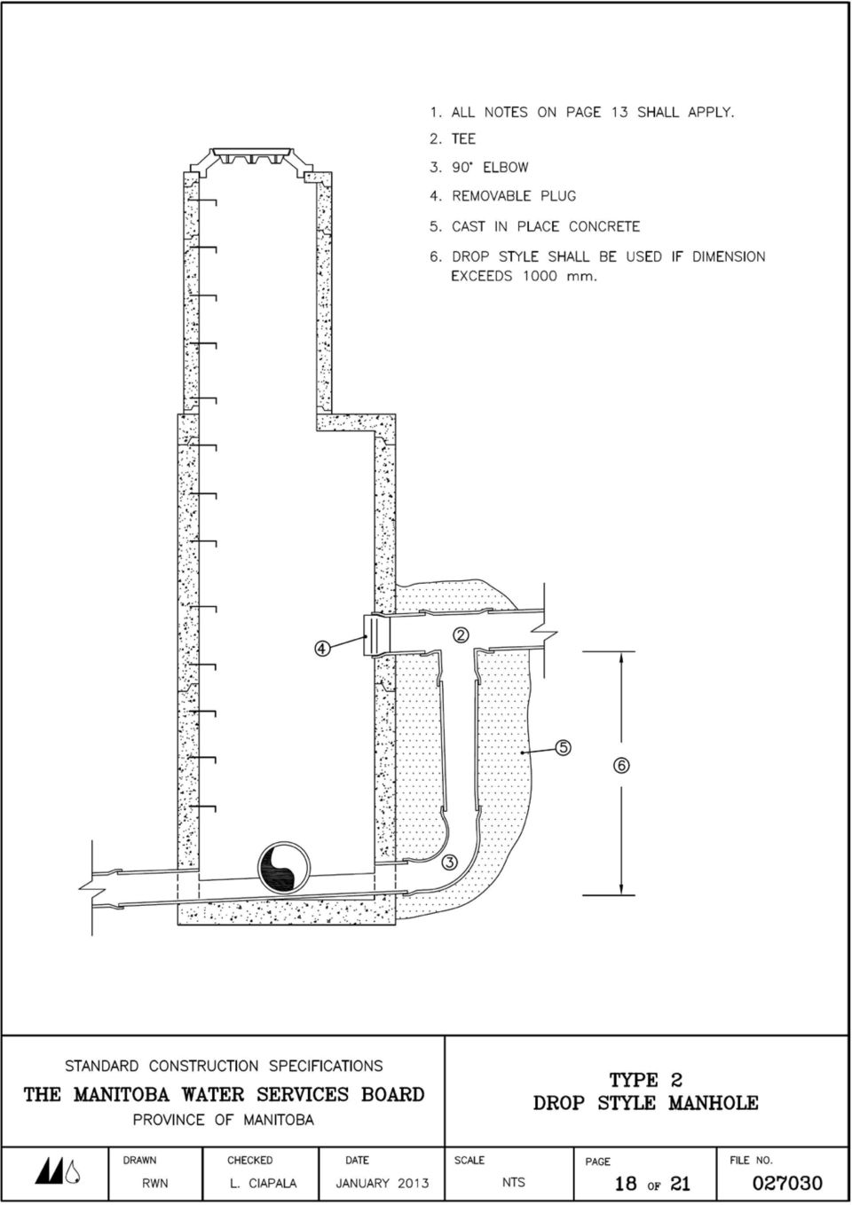
2 September 2013 Page 2 of 21.4 Type 4 - For 1500 mm or larger diameter lines..5 Type 5 - For Intersecting or Deflecting sewermains where sewermains are greater than 600 mm diameter..6 Type 2 Drop-Style for sewer lines 200 mm to 600 mm diameter where the difference in invert elevations exceeds one metre. Descriptions for each type of manhole may be found in the Typical Details of Manholes, Pages 13 to 18 of this Section..5 MANHOLE FRAME AND COVER UNITS - Frame and cover units shall be classified as either:.1 Solid.2 Open.3 Side Inlet.4 Rolled Curb and Gutter Descriptions of each type may be found in the Typical Details of Frame and Cover Units on Pages 19 and 20 of this Section..6 CONNECTION TO POINT OF DISCHARGE - The connection of the furthermost downstream portion of the sewer to a point of discharge shall be classified as either a connection to an existing plugged sewer stub, to a manhole, or to a wetwell. 1.3 STANDARDS The following organizations publish Standards which have been referred to in this Section:.1 CSA International 178 Rexdale Boulevard Toronto, Ontario M9W 1R3.2 ASTM American Society for Testing and Materials 100 Barr Harbor Drive West Conshohocken, PA USA The Standards referred to shall be the most recent edition

3 September 2013 Page 3 of QUALITY ASSURANCE.1 CONCRETE - The Engineer shall carry out such tests on concrete (used to grout manholes and catch basins) as he considers necessary, in accordance with the current CSA Standard A23.2, Methods of Test for Concrete. Such tests shall be at the expense of the Owner, except that the Contractor shall furnish any and all test samples free of charge. 1.5 STORAGE AND HANDLING.1 Pipe, fittings and appurtenant materials associated with the construction of the sewers shall be stored and handled in accordance with the recommendations of the respective manufacturer or as directed by the Engineer. 1.6 INSPECTION.1 Inspection of the work described in this Section shall be performed by the Engineer. Part 2 PRODUCTS 2.1 PIPE Unless otherwise specified in Section 01001, Special Provisions, pipe, saddles, tees, elbows, plugs and joining products shall be as follows:.1 PVC - Pipe and fittings shall be manufactured of Type 1 Grade 1 Polyvinyl Chloride in accordance with the current ASTM Standard D2241, Standard for Polyvinyl Chloride Pipe, ASTM3034, Standard Specification for Type PSM Poly (Vinyl Chloride) (PVC) Sewer Pipe and Fittings, CSA B182.1 Plastic Drain and Sewer Pipe and Pipe Fittings and CSA B182.2 PVC Sewer Pipe and Fittings. Each length of pipe shall have a bell end with a rubber gasket as supplied by the pipe manufacturer. Pipe lengths shall not exceed 6 m. The pipe shall be either PVC SDR 35 or PVC SDR 28 for sewermains, and PVC SDR 35 for sewer service connection pipe..2 PROFILE PVC SEWER PIPE - Profile PVC sewer pipe shall conform to CSA B182.4 Profile PVC Sewer Pipe and Fittings and ASTM F-794 Poly (Vinyl Chloride) (PVC) Profile Gravity Sewer Pipe and Fittings Based on Controlled Inside Diameter. The pipe shall have a cell classification of B in accordance with ASTM D1784. Pipe fittings shall be injection moulded to ASTM D3034 and CSA B Fabricated fittings for larger size fittings shall be in accordance with ASTM D3034, ASTM F679 and CSA B Gaskets for pipe and fittings shall be CSA and ASTM F477.

4 September 2013 Page 4 of 21.3 CONCRETE Pipe and fittings shall be extra strength concrete conforming to the current ASTM C14, Standard for Non-reinforced Concrete Sewer, Storm Drain and Culvert Pipe, for pipe up to 450 mm in diameter. Concrete pipe and fittings 525 mm in diameter and larger shall be Class II reinforced concrete conforming to the current ASTM C76-11 Standard for Reinforced Concrete Culvert, Storm Drain and Sewer Pipe. Each length of pipe of 150 mm to 525 mm in diameter shall be complete with a rubber gasket. Each length of pipe of 600 mm to 1.35 m shall be complete with either a rubber or "Ram-nek" flexible bituminous gasket. Each length of pipe with an inside diameter exceeding 1.35 m shall be complete with either a "Ram-nek" flexible bituminous gasket or with a mortar joint. Pipe shall not exceed 3 m in length. 2.2 MANHOLES.1 Manholes shall be fabricated of precast reinforced concrete in accordance with the current ASTM C478, Standard Specification for Precast Reinforced Concrete Manhole Section. Joints shall be complete with a "Ram-nek" flexible bituminous gasket. Cement used in precast concrete manhole manufacture shall be sulphate resistant meeting the current CSA Standard A5, Portland Cement, Type 50. Aluminium ladder rungs shall be cast into the manhole sections. 2.3 MANHOLE FRAME AND COVER UNITS.1 Frame and cover units shall be cast iron in accordance with ASTM A48, Standard Specification for Gray Iron Castings, Strength Class 30B. Castings shall be true to the required pattern and shall be free from cracks, gas holes, flaws and excessive shrinkage. Casting surfaces shall be free from burnt-on sand and shall be reasonably smooth. Runners, risers, fins and other cast-on pieces shall be removed. Adjustment riser rings shall be used for adjusting the elevation of cover units. 2.4 CONCRETE.1 Concrete used for grout and for forming benching channels in manholes shall have a 28 day compressive strength of not less than 15 MPa. Cement used in concrete shall be sulphate resistant meeting the current CSA Standard A5, Type 50 Portland cement. Water used for mixing concrete shall be clean and free from injurious amounts of oil, acid, alkali, organic matter or other deleterious substances. It shall be equal to potable (suitable for drinking) water in both physical and chemical properties. 2.5 GASKETS AND LUBRICANTS.1 Gaskets and lubricant used to join pipes and fittings shall be of a type compatible with the particular pipe or fitting being used.

5 September 2013 Page 5 of SEWERMAIN INSULATION (SHALLOW BURY).1 When in areas of shallow trench it shall be necessary to provide insulation over the top and sides of the pipe. The required insulation shall conform to CAN ULC S or CGSB-51-GP-20M type 4 rigid extruded polystyrene foam HI-40 (blue in colour) as manufactured by DOW chemical or approved equal with a compression strength of 275 kpa. A typical pipe insulation detail is shown on page 21 of this section. In the case of two pipes insulated in a common trench the insulation shall envelope both pipes. 2.7 RUNGS.1 Rungs shall be cast into the manhole precast concrete sections every 305 mm and shall be made in accordance with CSA G30.12, No. 25M Billet steel deformed bars, hot dipped, galvanized to CSA G164. Rungs shall be safety pattern (drop step type). Part 3 EXECUTION 3.1 EXCAVATION AND BEDDING BACKFILL.1 This portion of the work shall be in accordance with Section , Pipe Excavation, Bedding and Backfill. 3.2 GRADE AND ALIGNMENT.1 Sewer pipe shall be installed to the line and grade shown on the Plans and as set in the field by the Engineer. Vertical variance from grade shall not exceed the following limits; the invert of the pipe shall not be more than 12 millimetres below the design grade nor more than 12 millimetres above the design grade and there shall be no dips which will allow ponding of water to a depth of more than 25 millimetres. Horizontal variance from line shall not exceed 100 millimetres. Sharp bends will not be permitted even though the sewer pipe remains within these tolerances..2 Manholes, tees, wyes, reducers and bends shall be installed to the grades and at the locations shown on the Plans. The allowable tolerance from the line and grade shall not exceed those specified for sewer pipe. 3.3 CLEANING.1 Prior to installation, all interior and joining surfaces of all pipes and fittings shall be cleaned of dirt and foreign material and wiped dry.

6 September 2013 Page 6 of JOINING PVC PIPE.1 The pipe shall be installed with the bell end facing upstream unless otherwise specified by the Engineer. An integral rubber gasket shall be supplied in the bell end of the pipe. The manufacturer's recommended lubricant shall be applied to the bevelled spigot end. The spigot end shall be inserted into the bell end of the previously laid pipe to the stop mark which the manufacturer provides on the spigot end, such that a secure joint is obtained. 3.5 JOINING CONCRETE PIPE (BELL AND SPIGOT TYPE).1 The pipe shall be laid with the bell end facing upstream unless otherwise specified by the Engineer. Lubricant shall be applied to the spigot and gasket in the bell end of the pipe. The spigot end of the pipe shall be inserted into the bell end of the previously laid pipe such that a secure joint is obtained. 3.6 JOINING CONCRETE (TONGUE AND GROOVE TYPE).1 The pipe shall be laid with the groove end facing upstream unless otherwise specified by the Engineer. A gasket shall be placed on the tongue end of the pipe. The lubricant shall be applied to the tongue and groove ends of the pipe. The tongue end of the pipe shall be inserted into the groove end of the previously laid pipe such that a secure joint is obtained. 3.7 GENERAL JOINING PROCEDURE.1 Spigot or tongue ends of pipe may be inserted into the bell, coupling or groove ends of previously laid pipe by hand, or if additional force is required to effect complete insertion, the following may be used:.1 BAR AND BLOCK - If a bar is used for leverage, a wooden block shall be placed between the bar and the end of the pipe being pushed..2 LEVER-TYPE OR FRICTION PULLERS - When pullers are used, the chains shall be employed in a manner which does not cause damage to the pipe. 3.8 TUNNELLING.1 Where the sewer is to be installed by means of auguring, coring, pushing, or directional boring rather than by open cut trenching, the tunnel shall be of a diameter large enough to enable the pipes to be pushed through without interference or obstruction. The pits at either end of the tunnel shall be of adequate length to allow each pipe length to be lowered in parallel to the tunnel and joined to the length of pipe installed previously. The bell, coupling or grooved end of the previously installed pipe shall extend clear of the tunnel opening and be completely exposed to facilitate joining. The pipe lengths shall be
.1 The pipe shall be laid with the bell end facing upstream unless otherwise specified by the Engineer.")
7 September 2013 Page 7 of 21 securely joined in accordance with Clause 3.4, 3.5, 3.6 and 3.7 of this Section; whichever is appropriate. 3.9 CUTTING PIPE.1 If it is necessary to shorten a length of sewer pipe, the pipe shall be cut with a fine toothed hand saw, power saw (quicky saw) or hack saw, but not with a chain saw. Cut ends of PVC pipe shall be bevelled to the correct outside diameter with a fine file to duplicate the factory bevel on the spigot end of the pipe MANHOLES.1 Manholes shall be constructed in accordance with the typical manhole, Pages 13 to 18 of this Section..2 "Ram-nek" flexible bituminous gaskets shall be installed on each manhole section prior to lowering the section into the trench. Sections shall be lowered with care and properly aligned to ensure that all ladder rungs line up vertically..3 A flat top ring shall be installed on the riser just prior to the frame and cover unit..4 Subsequent to the installation of the precast concrete sections and frame and cover unit, all joints and holes for lifting lugs shall be sealed on the inside with grout..5 The outside of the precast concrete manhole sections shall be wrapped with 0.15 mm (6 mil) thick polyethylene which shall be taped tightly with duct tape prior to the placement of backfill. The polyethylene wrapping shall extend from the top of the manhole to the manhole base section..6 TYPE 1, 2 AND 5 MANHOLES - the sewer line shall be laid through the manhole. The line shall be cut lengthwise in the bottom of the manhole such that an outside semi-circular space shall be filled with concrete to the level of the middle of the semi-circular pipe. The concrete floor shall be graded at a 10:1 slope toward the channel formed by the pipe. When the Contractor installs PVC sewer pipe through cast-in-place manhole or precast concrete walls he shall ensure a water tight connection by coating the PVC pipe with an epoxy and apply a select granular material (i.e. sand) to the epoxy for a rough prepared surface prior to grouting the PVC sewer pipe in place, otherwise the Contractor shall install a "manhole adaptor" (i.e. GPK manhole adaptor) grouted into place to ensure a water tight connection..7 TYPE 1, 2, 3 AND 4 MANHOLE - The joints of the manhole pipe and stack unit shall be grouted externally and internally.

8 September 2013 Page 8 of 21.8 TYPE 2 - DROP MANHOLES - Drop manholes shall be constructed with tee and elbow sections encased in concrete as shown on the Typical Drop Manhole Detail, Page 18 of 21 of this Section CONNECTION TO POINT OF DISCHARGE.1 EXISTING PLUGGED SEWER - The plug shall be removed from the existing sewer. A new gasket shall be installed to join the existing pipe with the new pipe. Where the two pipes consist of different materials, a secure joint shall be made by placing sulphate resistant concrete around the joint between the two pipes or by installing an approved coupler or adaptor connecting the new to the existing sewer pipe..2 EXISTING MANHOLE - The wall of the existing manhole shall be exposed by excavation. A jackhammer or sledge hammer shall be used to create an opening in the wall at the point where the new pipe invert is to be located. Care shall be taken to ensure that the opening in the manhole is restricted to the immediate vicinity of the proposed pipe entry. The reinforcing steel in the area of the opening shall be cut. All rubble resulting from these operations is unsuitable material and shall be disposed of by removing it from the manhole. If a semicircular channel does not already exist in the bottom of the manhole, one shall be formed. Existing formed channel works shall be reformed (by jack hammering and placing concrete) if required. The new pipe shall be installed such that it forms a continuous channel in the manhole. The pipe shall be cut, concrete placed and all holes grouted. When the Contractor installs PVC sewer pipe through a cast-in-place manhole or precast concrete walls he shall ensure a water tight connection by coating PVC pipe with an approved cementing agent to which sand has been added prior to grouting the PVC sewer pipe in place, otherwise the Contractor shall install a "manhole adaptor" (i.e. GPK manhole adaptor) grouted into place to ensure a water tight connection or utilize a link seal complete with link seal sleeve..3 EXISTING WETWELL - An existing wetwell may be either a lift station, a portion of a sewage treatment plant, or a chamber. An opening shall be made in the wall of the wetwell in the same manner as described for existing manholes in Clause The pipe shall be inserted, grouted in, and cut flush with the inside wall SERVICE CONNECTIONS.1 Service lines shall be connected to the sewermains by means of either an in-line tee or a saddle. Tees shall be installed by the same method as is used to join the sewermain pipe. All saddles except PVC saddles shall be installed on the main and grouted in place using sulphate resistant cement for concrete. Appropriate

9 September 2013 Page 9 of 21 cutting tools shall be employed to cut a hole in the main for the service line prior to the installation of the saddle. PVC saddles shall be installed by means of the solvent-weld cement (in the case of solvent weld saddles) on PVC sewermain, complete with two all-stainless steel clamps. Saddles utilizing a gasket only, shall be installed in accordance with manufacturers recommendations and two allstainless steel clamps. Refer to Sewer Service Connection Detail on Page 12 of 21 in this Section..2 Elbows shall be used as required to connect service line pipe to the tee or saddle on the sewermain. Riser pipe shall be used as required to join sewer service lines to deep sewer mains..3 The end of each service line (which normally terminates at the limit of the road right-of-way) shall be sealed with an appropriate plug and a marker post installed at the ground surface TEMPORARY PLUGS.1 During prolonged pauses in the construction, such as meal breaks and overnight, the sewer lines shall be temporarily plugged with an approved plug to prevent the entry of foreign matter HYDROSTATIC TESTING Following the completion of construction, the appropriate hydrostatic test shall be performed as directed by the Engineer..1 INFILTRATION TEST - All accumulated water shall be removed from the sewermain prior to the commencement of the test. The Engineer shall observe the amount of accumulated infiltration over a 24 hour period. The Engineer shall calculate the amount of infiltration by establishing the volume of the pipes and manholes below the static water level in the manhole which is furthest downstream. The maximum allowable rate of infiltration shall be 0.15 litres per millimetre of inside diameter per 100 metres of pipeline per hour. This amount shall include infiltration through the manhole..2 EXFILTRATION TEST - The lines shall be filled with water and left to stand for 24 hours prior to commencing the test, in order to allow for absorption into the pipe and manhole walls. Thereafter, the manhole and sewermain shall be filled to the level determined by the Engineer. The Engineer shall observe the drop in level over a 2 hour period. The maximum rate of leakage shall be 0.20 litres per millimetre of inside diameter per 100 metres of pipeline per hour. An additional 3.0 litres per hour per metre of manhole riser above the invert shall be allowed for leakage through manholes.

10 September 2013 Page 10 of MANDREL If hydrostatic testing reveals excessive leakage, the Contractor shall repair the defective sewermains at his own cost and the test shall be repeated until leakage falls within the prescribed limit..1 At the discretion of the Engineer, the contractor shall subject PVC pipe sewers to a mandrel test with a rigid device sized to pass 5% or less deflection (deformation) after backfilling of the trench over the pipe. The Contractor may decide to test for pipe deflection following the consolidation of the trench backfill to be determined by the Engineer. The deflection following trench consolidation shall not be greater than 7.5 per cent. The mandrel shall be supplied by the Engineer for the Contractor's use. No allowance shall be made for pipe wall thickness tolerances or ovality (from heat, shipping, poor production, etc). The above shall be counted in as part of the deflection allowance. The mandrel shall be hand pulled by the Contractor through the sewer lines. Any sections of sewer not passing the mandrel test shall be excavated and the Contractor shall re-install or replace the sewermain to the satisfaction of the Engineer. The repaired sections shall be retested. The inspection shall be conducted no earlier than 30 days after reaching final trench backfill grade, provided in the opinion of the Engineer that sufficient water densification or rainfall has occurred to thoroughly settle the soil throughout the entire trench depth..2 If densification cannot be achieved in the time after installation prior to the project completion date, then the mandrel size shall be increased so that the rigid mandrels device would be sized to pass 4 percent or less deflection (deformation of the pipe diameter) BALL TESTING.1 All sewers (excepting those where the Engineer requires mandrel testing) shall be subject to ball testing by the Contractor..2 Ball testing shall comprise pulling a wood or metal ball through sewer lines between manholes, such a ball being 50 mm smaller in diameter than the internal diameter of the sewer being tested. If the ball does not pass readily through the sewer, the Contractor shall repair or replace or clean the defective sewer at the Contractor's expense and the test shall be repeated TELEVISION INSPECTION.1 The Contractor shall provide a television inspection when specified under Section of the Special Provisions or requested on site by the Engineer. The television inspection shall be complete with video recording of all completed gravity sewermains which have an internal diameter of 1200 millimetres or less.
 after backfilling of the")
11 September 2013 Page 11 of 21 The television inspection shall be done by personnel skilled and qualified in the use of the television inspection equipment. All televising equipment shall be the most current video format. The Contractor shall supply two sets of videos and a summary report to the Engineer. Inspection shall be between manholes or other appropriate locations where the equipment may be installed or removed. The section to be inspected shall not be broken down into units smaller than the distance between manholes or other appropriate locations as detailed above. The sewer shall be cleaned before the television inspection is done.

12

13

14

15

16

17

18
19

20

21
DIVISION 2 - SEWERAGE AND DRAINAGE SECTION 02720 - STORM DRAIN SYSTEMS PART 1 - GENERAL
 DIVISION 2 - SEWERAGE AND DRAINAGE SECTION 02720 - STORM DRAIN SYSTEMS PART 1 - GENERAL 1.01 DESCRIPTION A. Furnish and install all storm drains, including manholes, inlets, service lines and other appurtenant
SECTION 6 SANITARY SEWER MAIN 6.01 SCOPE
 6.01 SCOPE The work covered by this section of the specifications consists of the furnishing of all plant, labor, materials, equipment and supervision and performing all operations involved in the construction
SECTION 02400 - STORM DRAIN SYSTEM
 SECTION 02400 - STORM DRAIN SYSTEM CONTENTS: Part 1 - General... 1 1.01 Work Included... 1 1.02 Related Requirements... 1 1.03 Reference Standards... 1 1.04 Quality Assurance... 1 1.05 Measurement And
SECTION 02630 STORM DRAINAGE SYSTEM
 SECTION 02630 PART 1 - GENERAL 1.01 DESCRIPTION A. Section includes specifications for storm drainage systems including modifications and connections to existing storm drainage systems. 1.02 REFERENCE
SECTION 33 41 13 PUBLIC STORM UTILITY DRAINAGE PIPING
 SECTION 33 41 13 PUBLIC STORM PART 1 - GENERAL 1.01 SECTION INCLUDES A. Storm drainage piping, fittings, and accessories at proposed station areas and locations other than under and immediately adjacent
SECTION 33 11 00.11 POLYVINYL CHLORIDE (PVC) PIPE
 PIPE") SECTION 33 11 00.11 POLYVINYL CHLORIDE (PVC) PIPE PART 1: GENERAL 1.01 SECTION INCLUDES PVC pressure pipe and fabricated fittings in nominal sizes 4-inches through 12-inches with cast iron pipe equivalent
SECTION 33 11 00.11 POLYVINYL CHLORIDE (PVC) PIPE PART 1: GENERAL 1.01 SECTION INCLUDES PVC pressure pipe and fabricated fittings in nominal sizes 4-inches through 12-inches with cast iron pipe equivalent
A. Contractor shall furnish, to the Engineer, all materials certifications available from the manufacturer for all required materials.
 PART 1 GENERAL 1.1 SCOPE A. This item shall include the work necessary for the installation of storm sewer line construction. B. Reference Section 3800 Trenching and Backfill and the General Conditions,
Section 02702 SEWER PIPE INSTALLATION AND TESTING
 PART 1 - GENERAL Section 02702 SEWER PIPE INSTALLATION AND TESTING 1-1. SCOPE. This section covers the installation and testing of all sewer pipe furnished under the following specification sections: Concrete
STANDARD SPECIFICATIONS SECTION 02701 INSTALLATION OF GRAVITY SEWER PIPELINES. 1. Trenching, Backfilling and Compacting: 02223
 STANDARD SPECIFICATIONS SECTION 02701 INSTALLATION OF GRAVITY SEWER PIPELINES PART 1 - GENERAL A. Description This section describes the installation of gravity sewer pipelines fabricated of vitrified
SANITARY SEWER SPECIFICATIONS
 SANITARY SEWER SPECIFICATIONS OCTOBER 2003 HARVEST-MONROVIA WATER, SEWER, AND FIRE PROTECTION AUTHORITY SECTION 1.00 1.10 Purpose The purpose of this document is to assemble the sewer specifications, policies,
SECTION LS 2530 SANITARY SEWERS. A. General: Submit the following in accordance with The General Conditions.
 SECTION LS 2530 SANITARY SEWERS PART 1 GENERAL 1.1 SUBMITTALS A. General: Submit the following in accordance with The General Conditions. 1. Product data for drainage piping specialties. 2. Shop drawings
SECTION 02720 SANITARY SEWER AND STORM DRAIN SYSTEMS
 SECTION 02720 SANITARY SEWER AND STORM DRAIN SYSTEMS PART 1 GENERAL 1.01 SECTION INCLUDES A. The requirements for pipe material and installation in sewer and drainage collection systems. All materials
Wastewater Capital Projects Management Standard Construction Specification
 CITY AND COUNTY OF DENVER ENGINEERING DIVISION Wastewater Capital Projects Management Standard Construction Specification 10.1 Precast Concrete Pipe 10.1.1 General This section covers material requirements,
LS 2540 SEWER LATERALS AND INSPECTION TEES
 LS 2540 SEWER LATERALS AND INSPECTION TEES A. Summary B. Submittals C. Site Information D. Sewer Pipe and Fittings E. Lateral Locations F. Lateral Installation G. Inspection Tee Installation H. Removal
State of Illinois Department Of Transportation CONSTRUCTION INSPECTOR S CHECKLIST FOR STORM SEWERS
 State of Illinois Department Of Transportation CONSTRUCTION INSPECTOR S CHECKLIST FOR STORM SEWERS While its use is not required, this checklist has been prepared to provide the field inspector a summary
SECTION 55 PIPE FOR STORM DRAINS AND CULVERTS (FAA D-701)
") SECTION 55 PIPE FOR STORM DRAINS AND CULVERTS (FAA D-701) 55-1 GENERAL The Contractor shall perform all work required by the plans for construction of pipe for storm drains, precast polymer trench drains
SECTION 55 PIPE FOR STORM DRAINS AND CULVERTS (FAA D-701) 55-1 GENERAL The Contractor shall perform all work required by the plans for construction of pipe for storm drains, precast polymer trench drains
CHAPTER 6 - SANITARY SEWER
 CHAPTER 6 - SANITARY SEWER 6.1 GENERAL This section covers the requirements for PVC plastic sewer pipe materials and installation in sanitary sewer construction. 6.2 PIPE PVC gravity sewer pipe and fittings
SECTION 33 31 00.11 GRAVITY SANITARY SEWERS
 SECTION 33 31 00.11 GRAVITY SANITARY SEWERS PART 1: GENERAL 1.01 SCOPE A. Gravity sanitary sewers and appurtenances. 1.02 SUBMITTALS A. Conform to requirements of Section 01 33 00 Submittals. B. Submit
CW 2130 - GRAVITY SEWERS TABLE OF CONTENTS
 August 2010 CW 2130 - GRAVITY SEWERS TABLE OF CONTENTS 1. DESCRIPTION... 1 1.1 General... 1 1.2 Definitions... 1 1.3 Referenced Standard Construction Specifications... 1 1.4 Referenced Standard Details...
The work of this Section includes furnishing and installing Reinforced Concrete Pressure Pipe as shown on the Drawings and as specified.
 Section 33 0200- Page 1 of 4 PART 1 - GENERAL 1.1 DESCRIPTION OF WORK The work of this Section includes furnishing and installing Reinforced Concrete Pressure Pipe as shown on the Drawings and as specified.
INDEX. Sec. No. Items Page Nos.
 INDEX Sec. No. Items Page Nos. 1. Types of Pipe............... MSSP- 2 2. Concrete Pipe............... MSSP- 2 thru MSSP-3 3. ABS and PVC Truss Pipe............... MSSP- 3 4. ABS and PVC Solid Wall Pipe...............
DESIGN AND CONSTRUCTION GUIDELINES AND STANDARDS DIVISION 33 UTILITIES 33 00 00 SITE UTILITIES
 SECTION INCLUDES Domestic Water Fire Water Service Water Well Sanitary Sewer Storm Drains Foundation Drainage RELATED SECTIONS 03 30 00 Concrete 21 00 00 Fire Suppression - Sprinklers 22 00 00 Plumbing
Section 402. STORM SEWERS
 402.02 Section 402. STORM SEWERS 402.01. Description. This work consists of constructing storm sewers of the size and class required, including excavation, bedding, and backfill. 402.02. Materials. Provide
32-02.05 Precast Manhole Sections and Castings. These items shall conform to Section 31, "Storm Drain Installation," of these Standard Provisions.
 SECTION 32: SANITARY SEWER INSTALLATION 32-01 SCOPE. The Work shall consist of furnishing and installing sewer mains, manholes, laterals, cleanout fittings and appurtenances; and testing, flushing and
SUBDRAINS AND FOOTING DRAIN COLLECTORS. A. Construct subdrains, subdrain cleanouts and outlets, and footing drain collectors.
 SUBDRAINS AND FOOTING DRAIN COLLECTORS PART 1 - GENERAL 1.01 SECTION INCLUDES A. Subdrains B. Subdrain Cleanouts and Outlets C. Footing Drain Collectors D. Storm Sewer Service and Connections 1.02 DESCRIPTION
SECTION 9.02 BUILDING SUBSURFACE DRAINS (PERIMETER, ETC.)
") CHAPTER 9 SEWER / STORM DRAIN / IRRIGATION LINES SECTION 9.01 GENERAL This section covers the requirements for piping materials and installation of Lehi City sewer, storm drainage and irrigation collection
CHAPTER 9 SEWER / STORM DRAIN / IRRIGATION LINES SECTION 9.01 GENERAL This section covers the requirements for piping materials and installation of Lehi City sewer, storm drainage and irrigation collection
SECTION 08000 STORM DRAINAGE TABLE OF CONTENTS
 SECTION 08000 STORM DRAINAGE 08010 DESIGN A. Location B. Sizing TABLE OF CONTENTS 08020 MATERIALS A. Pipe Materials B. Structure Materials C. Installation D. Inlets and Outlets 08030 INSPECTIONS AND TESTING
San Antonio Water System Standard Specifications for Construction ITEM NO. 1100 SLIP-LINING SANITARY SEWERS
 ITEM NO. 1100 SLIP-LINING SANITARY SEWERS 1100.1 DESCRIPTION: This item shall consist of slip-lining sanitary sewer pipe, which is accomplished by pulling or pushing liner pipe into existing sewers by
DIVISION 4300 STORM DRAINAGE
 DIVISION 4300 STORM DRAINAGE SECTION 4305 STORM SEWER PART 1 - GENERAL 1.01 SCOPE This section covers the construction of storm sewers for the collection and transport of stormwater runoff. 1.02 REFERENCES
Beacon Hill Sewer District Standard Specifications
 Beacon Hill Sewer District Standard Specifications Residential Gravity Side Sewer Including Design Criteria and Standard Construction Drawings Residential Gravity Side Sewer Design Criteria 1. Provisions
SECTION 33 05 16.13 PRECAST CONCRETE UTILITY STRUCTURES
 SECTION 33 05 16.13 PRECAST CONCRETE PART 1 - GENERAL 1.01 SECTION INCLUDES A. This item shall consist of the construction of both sanitary and storm sewer precast concrete manholes in accordance with
SECTION 02530 STORM DRAINAGE STRUCTURES. 1. Trench excavation, backfill, and compaction; Section 02250.
 02530-1 of 5 SECTION 02530 STORM DRAINAGE STRUCTURES 02530.01 GENERAL A. Description Storm drainage structure construction shall include, but not necessarily be limited to, furnishing and installing or
TABLE OF CONTENTS SECTION 500 SANITARY SEWER AND FORCE MAIN
 TABLE OF CONTENTS SECTION 500 SANITARY SEWER AND FORCE MAIN Starts on Page 500 GENERAL... 2 501 MATERIALS... 2 502 CONSTRUCTION PROCEDURES... 7 503 ABANDONMENT OF EXISTING SANITARY SEWER FACILITIES...
CCU Engineering Specifications. Section 003300 PRECAST CONCRETE PRODUCTS
 CCU Engineering Specifications Section 003300 Effective Date: Nov. 1st, 2011 Page 1 of 5 PRECAST CONCRETE PRODUCTS PART 1 - GENERAL The following specification is intended for use for the design, selection
AIR RELEASE, CLEANOUT, AND SEWER MANHOLES
 AIR RELEASE, CLEANOUT, AND SEWER MANHOLES **From Hartford IM BLDG(10) DESCRIPTION. This work shall consist of the construction of air release, cleanout, and sanitary sewer manholes; and the furnishing
SECTION G SEWERS (STORM, SANITARY AND FDC)
") G-1 GENERAL SECTION G SEWERS (STORM, SANITARY AND FDC) The Consulting Engineer is to monitor all specified pipe and granular materials, pipe slopes and run lengths and ensure the outlined criteria below
G-1 GENERAL SECTION G SEWERS (STORM, SANITARY AND FDC) The Consulting Engineer is to monitor all specified pipe and granular materials, pipe slopes and run lengths and ensure the outlined criteria below
Section 2100-Trenching and Tunneling
 SECTION 5200 - STORM SEWER PART 1 - GENERAL 1.01 SCOPE: This Section covers installation of storm sewer mains and culverts. Topics include permits and fees, trench widths, pipe laying, bedding, initial
September 2012 Brunswick County Engineering Department Revision 1.0. Technical Specification 020.01 GRAVITY SANITARY SEWER SYSTEM
 1.0 General Technical Specification 020.01 GRAVITY SANITARY SEWER SYSTEM a) It is the intent of this specification to ensure that all gravity sewer system infrastructure constructed within the service
The Manitoba Water Services Board SECTION 022180 Standard Construction Specifications PIPE EXCAVATION, BEDDING AND BACKFILL Page 1 of 11
 Page 1 of 11 Part 1 General 1.1 DESCRIPTION OF WORK.1 The work described herein shall consist of the excavation of trenches (or excavation of tunnels); the supply and placing of bedding and backfill materials;
Royal Seal Gasketed Sewer Pipe
 Royal Seal Gasketed Sewer Pipe Royal Seal Gasketed Sewer Pipe Royal Seal gasketed sewer pipe with our specially designed Double Seal Locked-In (DSLI ) gasket is an extremely durable pipe with a leak proof
SECTION 6A STORM DRAIN DESIGN Mar. 2002 S E C T I O N 6A STORM DRAIN - DESIGN
 S E C T I O N 6A STORM DRAIN - DESIGN 6A.l Scope 6A.2 Storm Water Quantity 6A.3 Storm Drain Hydraulics 6A.4 Depths 6A.5 Locations 6A.6 Curved Storm Drains 6A.7 Manholes 6A.8 Catch basins 6A.9 Storm Drain
SECTION 03400 PRECAST CONCRETE STRUCTURES
 PART 1 GENERAL 1.01 SCOPE OF WORK A. Furnish all labor, materials, and equipment required to install precast concrete manholes, sanitary leaching rings, pump station, valve chamber, structures, frames,
SECTION 02401 - SANITARY SEWER PIPE
 PART 1 - GENERAL 1.1 DESCRIPTION A. The WORK under this Section includes providing all labor, materials, tools and equipment necessary for furnishing and installing sanitary sewer pipe, in accordance with
SECTION 200: STORM SEWER CONSTRUCTION STANDARDS
 SECTION 200: STORM SEWER CONSTRUCTION STANDARDS Page No. Description 200-2 201 GENERAL 200-2 201.1 SPECIFICATIONS 200-2 201.2 CONNECTION TO EXISTING FACILITIES 200-3 202 MATERIALS 200-3 202.1 PIPES 200-4
Bethel Township Municipal Authority (BTMA) RESIDENTIAL SEWER CONNECTION MANUAL
 RESIDENTIAL SEWER CONNECTION MANUAL") 155 E. Front Street (rear) Lititz, PA 17543 Phone (717) 625-1930 Fax (717) 625-1931 Bethel Township Municipal Authority (BTMA) RESIDENTIAL SEWER CONNECTION MANUAL CONSTRUCTION SPECIFICATIONS AND DETAILS
155 E. Front Street (rear) Lititz, PA 17543 Phone (717) 625-1930 Fax (717) 625-1931 Bethel Township Municipal Authority (BTMA) RESIDENTIAL SEWER CONNECTION MANUAL CONSTRUCTION SPECIFICATIONS AND DETAILS
SECTION 02732 BUILDING SEWERS. B. Connection of building sanitary drainage system to municipal sewers.
 SECTION 02732 BUILDING SEWERS PART 1 GENERAL 1.01 SECTION INCLUDES A. Lateral piping, fittings, and accessories. B. Connection of building sanitary drainage system to municipal sewers. 1.02 REGULATORY
SECTION 3 SANITARY SEWER DESIGN
 SECTION 3 SANITARY SEWER DESIGN 3.1 GENERAL DESIGN CRITERIA 3.1.1 Requirement for Sanitary Sewer 3.1.2 Design Approval 3.1.3 IEPA Permit Required 3.1.4 Differentiation Between Public and Private Sanitary
Section 2 Specification 2.18 Concrete and/or Corrugated Steel Storm Sewer TABLE OF CONTENTS
 TABLE OF CONTENTS 2.18 CONCRETE AND/OR CORRUGATED STEEL STORM SEWER... 1 2.18.1 GENERAL... 1 2.18.2 MATERIALS... 1 2.18.2.1 Storm Sewer Pipe... 1 2.18.2.2 Cement Mortar... 1 2.18.2.3 Granular Materials...
SERVICE LINE EXTENSION AND SERVICE LINE CONNECTION CONDENSED SANITARY SEWER SYSTEM INSTALLATION SPECIFICATIONS
 1001 SOUTH LEECHBURG HILL LEECHBURG, PA 15656 Phone: 724-845-9355 Fax: 724-845-1186 SERVICE LINE EXTENSION AND SERVICE LINE CONNECTION CONDENSED SANITARY SEWER SYSTEM INSTALLATION SPECIFICATIONS 1. General
SECTION 15076 CEMENT-MORTAR LINED AND COATED STEEL PIPE
 SECTION 15076 CEMENT-MORTAR LINED AND COATED (CML&C) STEEL PIPE PART 1 GENERAL 1.01 DESCRIPTION This section designates the requirements for steel pipe fabrication, test in shop, installation of steel
BEST PRACTICE GUIDELINES FOR CULVERT LINER SELECTION
 BEST PRACTICE GUIDELINES FOR CULVERT LINER SELECTION GENERAL Rehabilitation of culverts with pipe liners is one of several methods available for extending the life of an existing culvert. It is often cost
STANDARD SPECIFICATIONS SECTION 03461 PRECAST REINFORCED CONCRETE MANHOLES AND MANHOLE BASES. 1. Structure Earthwork: 02200
 STANDARD SPECIFICATIONS SECTION 03461 PRECAST REINFORCED CONCRETE MANHOLES AND MANHOLE BASES PART 1 - GENERAL A. Description This section includes materials, testing, and installation of precast concrete
SECTION 02612 NONREINFORCED CONCRETE SEWER PIPE
 SECTION 02612 PART 1 GENERAL 1.1 SUMMARY A. Section Includes: Furnishing and installing nonreinforced concrete sewer pipe. Provide concrete sewer pipe less than 12 inches in diameter, and in other sizes
ASTM C76, Class III, Wall B, except as modified herein. Clean natural sand, ASTM C33. Artificial or manufactured sand will not be permitted.
 SECTION 3000 - SANITARY SEWERS 3001 SCOPE. This section applies to sanitary sewer construction and shall consist of furnishing all labor, materials, and equipment for the complete installation of sewers
SECTION 15125 HIGH DENSITY POLYETHYLENE (HDPE) PIPE AND FITTINGS FOR WATER DISTRIBUTION AND TRANSMISSION
 PIPE AND FITTINGS FOR WATER DISTRIBUTION AND TRANSMISSION") SECTION 15125 HIGH DENSITY POLYETHYLENE (HDPE) PIPE AND FITTINGS FOR WATER DISTRIBUTION AND TRANSMISSION PART 1 GENERAL.01 SECTION INCLUDES Furnishing and installing 4 inch through 16 inch high density
SECTION 15125 HIGH DENSITY POLYETHYLENE (HDPE) PIPE AND FITTINGS FOR WATER DISTRIBUTION AND TRANSMISSION PART 1 GENERAL.01 SECTION INCLUDES Furnishing and installing 4 inch through 16 inch high density
SECTION 9. All sewer laterals shall tie into the sewer main lines unless approved by the City Engineer.
 SECTION 9 SEWER/DRAINAGE LINES 9.1 GENERAL This section covers the requirements for piping materials and installation in the Cedar Hills City sewer and drainage collection system. All materials and workmanship
TECHNICAL SPECIFICATIONS GRAVITY AND PRESSURE SEWER LINE AND MATERIALS
 TECHNICAL SPECIFICATIONS GRAVITY AND PRESSURE SEWER LINE AND MATERIALS Scope of Work Work performed under this contract shall consist of furnishing and installing, complete and ready for service, the sewer
SECTION 724 PIPE CULVERTS
 SECTION 724 PIPE CULVERTS 724.1 Description. This work shall consist of providing pipe or pipe arch of the diameter or shape designated, laid upon a firm bed and backfilled as specified. Where appropriate
900 SEWERAGE WORK ITEM 901 - PIPE SEWERS COMPLETE IN PLACE
 900 SEWERAGE WORK ITEM 901 - PIPE SEWERS COMPLETE IN PLACE 901.01 Description 901.02 Materials and Material Handling 901.03 Excavation 901.04 Limit as to Width of Trench 901.05 Unauthorized Excavation
08003-1 WATER SERVICE 2
 08003_Mar08_2011.pdf Page 1 of 7 INDEX Page 08003-1 WATER SERVICE 2 1.1 Pipe 2 1.1.1 Copper 2 1.1.2 Polyethylene 2 1.2 Valves and Fittings 2 1.2.1 Main Stops 3 1.2.2 Curb Stops 3 1.2.3 Curb Box 3 1.2.4
SECTION 02700 SEWERAGE AND DRAINAGE PART 1 - GENERAL 1.01 RELATED DOCUMENTS
 SECTION 02700 SEWERAGE AND DRAINAGE PART 1 - GENERAL 1.01 RELATED DOCUMENTS A. Drawings and general provisions of the Contract, including the General and Supplementary Conditions and Division 1 Specification
STANDARD SPECIFICATIONS FOR PRIVATE BUILDING SEWER LINES IN PUBLIC RIGHT-OF-WAY
 STANDARD SPECIFICATIONS FOR PRIVATE BUILDING SEWER LINES IN PUBLIC RIGHT-OF-WAY Approved and adopted as Official Document Number 800576 this 10th day of December, 1980 Donald R. Boyd, P.E., Director Water
City of Regina Standard Construction Specification SECTION 1320 SEWERMAIN TESTING
 1.0 GENERAL 1.1 Scope 2.0 PRODUCTS 1.1.1 The work shall consist of testing wastewater and/or storm mains to ensure construction conforms to the proper line, grade, cross section and performance. 2.1 The
ARTICLE VI (ALTERNATE) STANDARD SPECIFICATIONS. for (PVC) SANITARY SEWER MAIN CONSTRUCTION
 STANDARD SPECIFICATIONS. for (PVC) SANITARY SEWER MAIN CONSTRUCTION") ARTICLE VI (ALTERNATE) STANDARD SPECIFICATIONS for (PVC) SANITARY SEWER MAIN CONSTRUCTION VI(A).1 General VI(A).2 Materials and Equipment VI(A).3 Installation of Sanitary Sewer Mains VI(A).4 Laying of
ARTICLE VI (ALTERNATE) STANDARD SPECIFICATIONS for (PVC) SANITARY SEWER MAIN CONSTRUCTION VI(A).1 General VI(A).2 Materials and Equipment VI(A).3 Installation of Sanitary Sewer Mains VI(A).4 Laying of
PUBLIC WORKS DESIGN, SPECIFICATIONS & PROCEDURES MANUAL LINEAR INFRASTRUCTURE
 REGION OF PEEL PUBLIC WORKS DESIGN, SPECIFICATIONS & PROCEDURES MANUAL LINEAR INFRASTRUCTURE Storm Sewer Design Criteria REVISED July 2009 PUBLIC WORKS STORM SEWER DESIGN CRITERIA TABLE OF CONTENTS 1.0
SECTION 33 11 00.15 DUCTILE IRON PIPE AND FITTINGS
 SECTION 33 11 00.15 DUCTILE IRON PIPE AND FITTINGS PART 1: GENERAL 1.01 COORDINATION OF WORK Connection to existing pipelines may require shutdown of AW facilities. Closely coordinate construction work
CITY OF BEVERLY RULES AND REGULATIONS - SEWER SYSTEM TESTING. General
 General All sanitary sewers, manholes and force mains shall be acceptance tested, as hereinafter specified in the presence of a City representative. Acceptance testing shall be performed after backfilling
Specification for Pipe Bursting Gravity Sewer Mains with HDPE Pipe
 Specification for Pipe Bursting Gravity Sewer Mains with HDPE Pipe 1. GENERAL The following supplemental sewer main specifications are intended to address the installation of high-density polyethylene
SPECIFICATIONS FOR SEWER PIPE AND LINING INSERTION - TRENCHLESS; GENERAL GUIDELINES (As Provided by NASSCO)
") SPECIFICATIONS FOR SEWER PIPE AND LINING INSERTION - TRENCHLESS; GENERAL GUIDELINES (As Provided by NASSCO) 1 Intent: The intent of trenchless sewer pipe Insertion is to rehabilitate the existing sewer
SPECIFICATIONS FOR SEWER PIPE AND LINING INSERTION - TRENCHLESS; GENERAL GUIDELINES (As Provided by NASSCO) 1 Intent: The intent of trenchless sewer pipe Insertion is to rehabilitate the existing sewer
SECTION 15105 DUCTILE IRON PIPE AND FITTINGS
 SECTION 15105 DUCTILE IRON PIPE AND FITTINGS PART 1 GENERAL.01 COORDINATION OF WORK Connection to existing pipelines may require shutdown of Owner facilities. Closely coordinate construction work and connections
SECTION 36 - CAST-IN-PLACE CONCRETE PIPE (CIPCP) TABLE OF CONTENTS
 TABLE OF CONTENTS") SECTION 36 - CAST-IN-PLACE CONCRETE PIPE (CIPCP) TABLE OF CONTENTS Section Page 36-1 GENERAL... 36.1 36-2 PIPEMAKING EQUIPMENT... 36.1 36-3 TRENCH EXCAVATION... 36.1 36-4 SPECIAL FOUNDATION TREATMENT...
SECTION 36 - CAST-IN-PLACE CONCRETE PIPE (CIPCP) TABLE OF CONTENTS Section Page 36-1 GENERAL... 36.1 36-2 PIPEMAKING EQUIPMENT... 36.1 36-3 TRENCH EXCAVATION... 36.1 36-4 SPECIAL FOUNDATION TREATMENT...
SECTION 33 41 03 POLYVINYL CHLORIDE (PVC) PIPE
 PIPE") SECTION 33 41 03 POLYVINYL CHLORIDE (PVC) PIPE PART 1 GENERAL 1.01 SECTION INCLUDES A. This section includes all labor, materials, equipment, and incidentals required and installation of Polyvinyl Chloride
SECTION 33 41 03 POLYVINYL CHLORIDE (PVC) PIPE PART 1 GENERAL 1.01 SECTION INCLUDES A. This section includes all labor, materials, equipment, and incidentals required and installation of Polyvinyl Chloride
FY11 Sanitary Sewer Main Rehab and Point Repair Bid Tabulation
 644-10-569 Page 1 of 9 1 FOR CLEANING AND TELEVISING EXISTING SEWERS, AS SPECIFIED, ANY REQUIRED CLEANING, ANY LOCATION, ANY LENGTH OF SEWER, COMPLETE IN PLACE, FOR VARIOUS PIPE DIAMETERS. A. EXISTING
Storm Sewer Trenchless Upgrade Alternatives and Recommendations
 Storm Sewer Trenchless Upgrade Alternatives and Recommendations Background Approximately 1,930 feet of the 40-inch and 42-inch CMP storm sewer pipe from manhole M22 to manhole M12 will be evaluated for
San Antonio Water System Standard Specifications for Construction ITEM NO. 1103 POINT REPAIRS AND OBSTRUCTION REMOVALS
 ITEM NO. 1103 POINT REPAIRS AND OBSTRUCTION REMOVALS 1103.1 DESCRIPTION: 1. Repair of sanitary sewer lines by replacing short lengths of failed pipe with new pipe. 2. Repair of service laterals located
3. Contractor shall ensure that all permits are obtained prior to any construction. Contractor shall be responsible for all utility fees.
 The following shall serve as the minimum requirements for contractors performing work in relation to the Authority s potable water and sanitary sewer system(s), appurtenances and service connections. General:
volume of concrete occupied by the drain pipe in a cast-in-place structure or structure extension.
 715.01 430 volume of concrete occupied by the drain pipe in a cast-in-place structure or structure extension. No additional payment will be made for the repair or replacement of existing concrete damaged
City of West Linn Public Works Standard Construction Specifications. Table of Contents
 City of West Linn Public Works Standard Construction Specifications Table of Contents DIVISION SIX STORM DRAIN TECHNICAL REQUIREMENTS... 1 601 PIPE AND FITTINGS... 1 601.01 Description...1 601.02 Materials...1
FY08 SEWER POINT REPAIRS BID TABULATION
 6-07-831 Page 1 of 12 1 FOR CLEANING AND TELEVISING EXISTING SEWERS, AS SPECIFIED, ANY REQUIRED CLEANING, ANY LOCATION, ANY LENGTH OF SEWER, COMPLETE IN PLACE, FOR VARIOUS PIPE DIAMETERS. A. EXISTING "
Section C-1 Pipes and Fittings
 Section C-1 Pipes and Fittings C1.00 Work Included The work under this Division of the Specifications shall include all labor, materials, and equipment necessary to furnish and install all piping, pipelines,
STANDARD CONSTRUCTION SPECIFICATIONS FOR SANITARY SEWERS DIVISION 50 INDEX
 STANDARD CONSTRUCTION SPECIFICATIONS FOR SANITARY SEWERS DIVISION 50 INDEX SECTION 50.01 GENERAL... 1 Article 1.1 Scope of Work... 1 Article 1.2 Applicable Standards... 1 Article 1.3 Surveys... 2 Article
NAPCA BULLETIN 18-99 APPLICATION PROCEDURES FOR CONCRETE WEIGHT COATING APPLIED BY THE COMPRESSION METHOD TO STEEL PIPE
 NAPCA BULLETIN 18-99 APPLICATION PROCEDURES FOR CONCRETE WEIGHT COATING APPLIED BY THE COMPRESSION METHOD TO STEEL PIPE GENERAL a. These specifications may be used in whole or in part by any party without
SECTION 7- STORM SEWER
 SECTION 7- STORM SEWER 7.1. STORM SEWERS.... 7-1 7.2. SUMP DRAINS... 7-3 7.3. CATCH BASINS... 7-3 7.4. MANHOLES... 7-4 7.5. STORM SEWER CALCULATIONS... 7-4 7.6. CULVERTS AND BRIDGES... 7-5 7.7. OPEN CHANNELS...
Special Specification 7021 Water Main and Sewer Line Replacements
 Special Specification 7021 Water Main and Sewer Line Replacements 1. DESCRIPTION Furnish, install, or replace water pipe, water valves, water meters and boxes, water service connections, fire hydrant assemblies,
SECTION 21 REHABILITATION OF SANITARY SEWER MAINS BY THE PIPE BURSTING AND TRENCHLESS PIPE REPLACEMENT METHOD
 SECTION 21 REHABILITATION OF SANITARY SEWER MAINS BY THE PIPE BURSTING AND TRENCHLESS PIPE REPLACEMENT METHOD 21.01 SCOPE: It is the intent of the Specification to define the approved methods and materials
8.01 STORM SEWERS, CATCH BASIN LEADS, AND EXTENSIONS
 8.01 STORM SEWERS, CATCH BASIN LEADS, AND EXTENSIONS 8.01.01 Description This work shall consist of installing lines of storm sewer pipe of the required inside diameter, and the necessary appurtenances,
Guide to working on Public Sewers
 Guide to working on Public Sewers affected by Building Works Introduction Severn Trent Water Ltd requires the work to be done in order to protect the public sewer and minimise the risk of us having to
CLEANING, INSPECTION, AND TESTING OF SEWERS
 CLEANING, INSPECTION, AND TESTING OF SEWERS PART 1 - GENERAL 1.01 SECTION INCLUDES A. Cleaning, Inspecting, and Testing Sanitary Sewers B. Cleaning, Inspecting, and Testing Storm Sewers C. Cleaning and
SECTION 33 31 00.13 ABANDONMENT OF SEWER MAINS
 SECTION 33 31 00.13 ABANDONMENT OF SEWER MAINS PART 1: GENERAL 1.01 SECTION INCLUDES A. Abandonment in place, by cutting and capping, of existing sewers, junction structures, manholes, service lines, and
SECTION 603 SANITARY SEWER FORCE MAINS
 SECTION 603 SANITARY SEWER FORCE MAINS 1. GENERAL Pipelines for sanitary sewer force main systems shall conform to the following specifications and shall be installed at the locations indicated on the
SECTION 33 41 00 REINFORCED CONCRETE PIPE. A. The following is a list of SPECIFICATIONS, which may be related to this section:
 SECTION 33 41 00 REINFORCED CONCRETE PIPE PART 1 GENERAL 1.01 SECTION INCLUDES A. This section includes construction of reinforced concrete pipe for storm drainage, culverts, and sanitary sewer, including
SECTION 02150 REMOVAL OR ABANDONMENT OF EXISTING UTILITIES AND UNDERGROUND STRUCTURES. 1. Trench excavation, backfill, and compaction; Section 02250.
 02150-1 of 6 SECTION 02150 REMOVAL OR ABANDONMENT OF EXISTING 02150.01 GENERAL A. Description Removal or abandonment of existing utilities and underground structures shall include, but not necessarily
550 PIPE CULVERTS, SEWERS AND DRAINS
 551.01 550 PIPE CULVERTS, SEWERS AND DRAINS 551 GENERAL 551.01 Description 551.02 Materials 551.03 Excavation 551.04 Protection of Excavation 551.05(a) Bedding for Rigid Pipe 551.05(b) Bedding for Non-Rigid
EXHIBIT "A. Technical Specifications for Water and Sewer Service Lines
 EXHIBIT "A Technical Specifications for Water and Sewer Service Lines Water and Sewer Line Bedding and Backfill: Drawings show cross-section of trench, pipe laid on top of 6" min. bedding material, bedding
STANDARD SPECIFICATIONS & CONSTRUCTION DETAILS MANUAL SECTION 5 - STORM DRAINAGE. 5.01 Design
 SECTION 5 - STORM DRAINAGE 5.01 Design Storm drainage facilities shall be designed in accordance with the goals and guidelines set forth in the Unified Development Ordinance. The goal shall be to collect
Exhibit A. Rules and Regulations for House Connections and Sewer Extensions
 The purpose of this application example is to provide assistance to small and medium sized rural communities in the drafting of documents necessary for the efficient operation of water, wastewater, and
STANDARD SPECIFICATIONS FOR STORM SEWER CONSTRUCTION CITY OF PLYMOUTH, MINNESOTA
 STANDARD SPECIFICATIONS FOR STORM SEWER CONSTRUCTION CITY OF PLYMOUTH, MINNESOTA MARCH 2014 ENGINEERING DIVISION 3400 PLYMOUTH BLVD. PLYMOUTH, MN USA 55447-1482 TELEPHONE (763) 509-5500 Doran M. Cote,
SECTION 02110 - ASBESTOS CEMENT PIPE REPAIRS, DEMOLITION, AND DISPOSAL
 SECTION 02110 - ASBESTOS CEMENT PIPE REPAIRS, DEMOLITION, AND DISPOSAL PART 1 - GENERAL 1.1 WORK INCLUDED IN THIS SECTION A. The WORK of this Section includes the repair, demolition, and disposal of asbestos
STANDARD SPECIFICATIONS SECTION 02512 CLEANING AND LINING WATER MAINS
 STANDARD SPECIFICATIONS SECTION 02512 CLEANING AND LINING WATER MAINS PART 1 GENERAL 1.1 DESCRIPTION A. Section includes requirements for cleaning and lining existing cast iron and ductile iron water mains
SPECIFICATION FOR PIPE SUBSOIL DRAIN CONSTRUCTION
 SPECIFICATION FOR PIPE SUBSOIL DRAIN CONSTRUCTION 1. SCOPE Pipe subsoil drains shall be constructed in accordance with this specification and in conformity with the lines, grades and cross-sections shown