Virtual CRASH 3.0 Staging a Car Crash
|
|
|
- Ursula Parker
- 8 years ago
- Views:
Transcription
1 Virtual CRASH 3.0 Staging a Car Crash

2 Virtual CRASH Virtual CRASH 3.0 Staging a Car Crash Changes are periodically made to the information herein; these changes will be incorporated in new editions of this program and related publications. This publication has been provided pursuant to an agreement containing restrictions on its use. This publication is also protected by federal and international copyright law. No part of this publication may be copied, distributed, transmitted, transcribed, stored in a retrieval system, or translated into any human or computer language, in any form or by any means, electronic, mechanical, magnetic, manual, or otherwise, or disclosed to third parties without the express written permission of: (V2.2) 2

3 2016 vcrash, Americas, Inc. All Rights Reserved 3

4 Virtual CRASH 3.0 Staging a Car Crash 4

5 5

6 Contents Introduction... 7 RICSAC Import Scale Diagram... 9 Place Vehicles into Scene Modify Vehicle Data Touch-up the Vehicle Mesh Place Vehicles at Pre-Impact Positions Modify the Tire Adhesion Values Enter Rolling Resistance Values Begin Iterating the Pre-Impact Speeds Open the Report Collision Data Create User Contact Adjust the Impulse Centroid Position Adjust a Few Other Parameters References

7 Introduction In Virtual CRASH 3.0 one can setup and refine a collision sequence with incredible speed. Virtual CRASH automatically updates simulations in real time as input parameters are tuned and adjusted. In this write-up we will explore how to simulate a collision between two automobiles. The exact same techniques will be applicable to collisions involving pickup trucks, commercial vehicles, or any other vehicle type. We will attempt to reproduce results from a staged collision test from the Research Input for Computer Simulation of Automobile Collisions (RICSAC) series. In this reconstruction, we will attempt to solve for the pre-impact speeds given knowledge of the preimpact orientations and post-impact rest positions and orientations. The purpose of this write-up is to show the Virtual CRASH user the typical workflow used during an accident reconstruction analysis; it is not intended to be a refined study of RICSAC collisions, as such studies have been performed by other researchers. We recommend reading references (1), (2), and (3) for more information on the RICSAC tests and test conditions. A video of the resulting simulation can be found online at: RICSAC 1 In the RICSAC 1 collision, a 1974 Chevrolet Chevelle Malibu impacted a 1974 Ford Pinto. Figure 1 depicts the impact configuration, as well as pre and post-impact trajectories. 7
 series.")
8 Figure 1 8
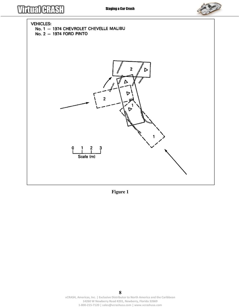
9 Import Scale Diagram Using the procedure outlined in reference (4), import the diagram shown in Figure 1 into the Virtual CRASH environment (Figure 2). You can copy and paste the diagram directly from this pdf file by simply copying a screen capture, pasting into Window s Paint application, and using the crop tool. After you have imported, scaled, and oriented your diagram, it is recommended you freeze the image object to prevent accidental modification as you build your simulation. Figure 2 9

; this form is")
10 With the scale diagram as your environment s backdrop, you can easily place additional graphical elements into your Virtual CRASH scene to suit your needs. In this example, the scale diagram was rotated and positioned so that it properly aligned with the impact and rest positions described in the Summary Form of page 2-8 of reference (2); this form is shown in Table 1 below. Note the data shown in this table is assuming SAE conventions, with the z-axis running parallel with gravitational acceleration, whereas in Virtual CRASH, the z-axis is aligned anti-parallel with gravity. This implies one must take y -y and yaw -yaw when reading data from this table for use in Virtual CRASH. The diagram was further refined using the Axes tool, which allows one to place a coordinate axis system within the environment. This tool also allows the user to place points within the x-y plane. This feature was used in order to place crosshairs at the impact and rest positions of each vehicle (Figure 3). The Text tool was used to annotate the diagram. Figure 3 10

11 Table 1 11

, one can look for reasonable exemplar vehicle shells for the subject vehicles. In this case, a Skoda Felicia seems to reasonably match the body style of the Pinto.")
12 Place Vehicles into Scene Now that we ve finished building our simulation environment, we are ready to place our vehicle models into the scene. Looking through reference (5), one can look for reasonable exemplar vehicle shells for the subject vehicles. In this case, a Skoda Felicia seems to reasonably match the body style of the Pinto. To place a vehicle into the scene, left-click on the + symbol next to cars in the left side control panel to reveal the car library. Next left-click on the + symbol next to Skoda, and then left-click and hold Felicia. Drag the mouse into the scene and release the left mouse button. You should see the vehicle model in the scene (Figure 4). Figure 4 12

.")
13 Using this same procedure, we will next place an AMC Matador into the scene as our exemplar for the Malibu (Figure 5). Figure 5 13
.")
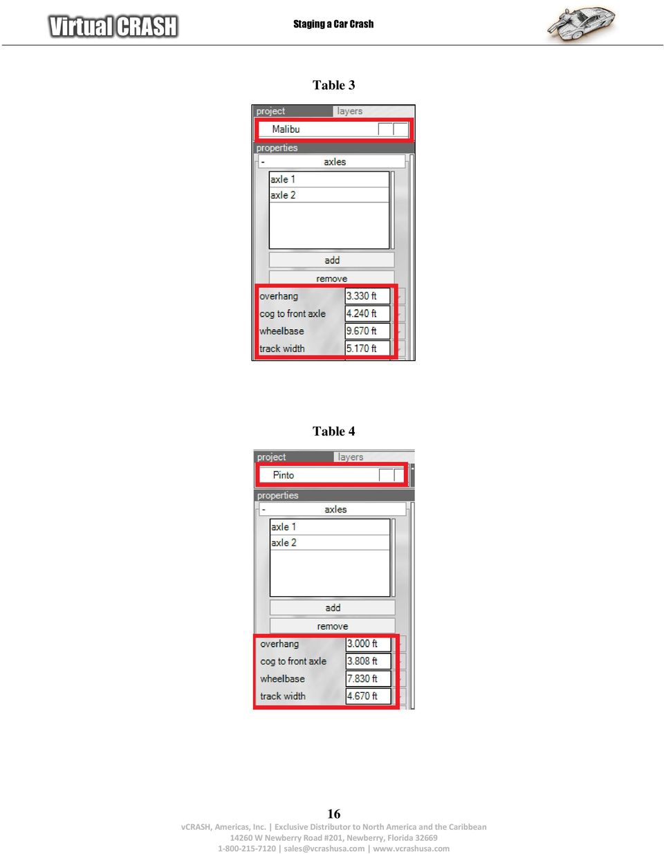
14 Modify Vehicle Data Using the methods described in reference (6), modify your vehicle properties to match the geometric size of each vehicle, center-of-gravity positions, and wheel placement (Figure 6). In this case, the weights were taken from the Crash Test Summary on page 7-4 of reference (3) (shown as Table 2 below), whereas the wheel position (Table 3 and Table 4) and size data (Table 5 and Table 6) were taken from Expert Autostats. On page 7-20 of reference (3), the front/rear weight distributions are given for both vehicles. Using this distribution, we can solve for a more precision value for the distances between the centers-of-gravity and the front-axles. Doing this, one obtains 3.81 ft between the cg and front axle for the Pinto, and 4.24 ft for the Malibu. Note, when the cg location is adjusted after a vehicle has already been placed in the scene, take care to reposition the initial start positioning to the desired location as it will shift when the cg location is modified. Figure 6 14

15 Table 2 15


16 Table 3 Table 4 16

17 Table 5 Table 6 17

. Using the method described in reference (7), the vertices can be easily adjusted to correct this problem (Figure 8).")
18 Touch-up the Vehicle Mesh Now that the vehicle wheels have been repositioned to match the Autostats data, the Pinto s vehicle mesh needs to be touched up to correct the awkward relative position of the rear wheels and the rear wheel wells (Figure 7). Using the method described in reference (7), the vertices can be easily adjusted to correct this problem (Figure 8). Figure 7 18
, the vertices can be easily adjusted to correct")

19 Figure 8 19

 and the Pinto should be placed at (0.0, 5.5, 90 deg).")
20 Place Vehicles at Pre-Impact Positions Using the data in Table 1, we can place the vehicles at their pre-impact positions. The Malibu should be given coordinates (x,y,yaw) = (-10.8 ft, y=-1.0 ft, -30 deg) and the Pinto should be placed at (0.0, 5.5, 90 deg). The vehicle positions can be precisely controlled using the position-local menu in the left side control panel, and the orientations can be controlled using the rotation-local menu (Figure 9). Figure 9 20

21 Modify the Tire Adhesion Values Go to the left side control panel and click on the name of your Malibu vehicle. Hold the left mouse button and drag it down so that you also select the name of your Pinto vehicle; this is another way to select multiple objects at once. You can use the left control panel menus to modify values that are common to simultaneously selected objects. You should notice both vehicles have red boxes in the simulation environment indicating they are both currently active selections (Figure 10). Next, go to the contact menu and change the locked-wheel drag factor adhesion value to =0.87 (Figure 11) as indicated by the tire pavement drag factor in Table 1. Figure 10 21
22 Figure 11 22
23 Enter Rolling Resistance Values With both vehicles still selected, go to the left side control panel and left-click on sequences to access the braking data. Next, left-click on the empty box to the left of wheels separately to adjust the braking at each wheel as a percentage of the adhesion value. Table 1 indicates that the rear wheels of both vehicles had a drivetrain resistance of 20% whereas the front wheels had a rolling resistance of 1%. Set the brake lag value to 0 seconds so that the braking is enabled at time = 0 seconds (Figure 12). Figure 12 23
24 Begin Iterating the Pre-Impact Speeds With the pre-impact configuration set, we are now ready to optimize our simulation. Here we assume no initial knowledge of the pre-impact speeds. In order to converge upon a final solution for our reconstruction, we must iterate across our physics model s input parameters, which must be kept within a physically meaningful range. It is possible that given a final post-impact state which we are trying to match, there can be multiple solutions which do equally as well to match our intended goal; in this case our goal is have the vehicles come to rest as close as they can to the measured rest positions. Let s start by increasing the pre-impact speed of the Malibu. Go to the dynamics menu and slide the speed up until you see the Malibu stop near the final position marked on the diagram (Figure 13). You can use your mouse s scroll wheel to move the v slider. Note, at about 15 mph, the Malibu comes close to the final position. Figure 13 24

25 Now adjust the Pinto s initial speed. You ll notice that the Virtual CRASH system automatically updates and plays the simulation based on your current inputs (Figure 14). At 15 mph pre-impact speed for both vehicles, the Pinto is about a car-width short of the final target, implying there is not enough initial kinetic energy for the Malibu in the current simulation. Iteratively increase the speeds of each vehicle until a better match is found. Figure 14 25
26 We will stop this first round of iterating with v[malibu] = 19.9 mph and v[pinto] = 16.8 mph. In this case, both vehicles are much closer to their rest points (Figure 15). Figure 15 26

27 Open the Report To see how well we re doing so far with our simulation, go to the left side control panel and left click on report dynamics in the tools menu (Figure 16). We only need to look at the final positions of the vehicles, so set the time increment setting to 1 second. This will display the vehicle data every second in the report table. Now we can read off the final positions and orientations of the vehicles. The final (x,y,yaw) configuration for the Malibu is ( ft, ft, deg) and is (8.274 ft, ft, deg) for the Pinto. Figure 16 27
.")
28 Collision Data Using the methods shown in reference (8), access the first impact collision data by left-clicking on auto-ees and then selecting next contact in the left control panel. In the defaults menu, we can see the collision model parameters used. Under object 1 we see that the Pinto s v = mph and the Malibu s v = mph (Figure 17). These values could also have been obtained in the report, by setting the output time increment value to a much smaller value and reading off and analyzing the velocity vector data just before and just after impact. The results for the current state of our simulation are shown in Figure 16 below. The results are summarized in Table 7. Thus far, the largest discrepancy appears to be the final position and orientation of the Malibu. Our initial velocity estimates are already to within 16% of the measured values, and we were able to determine this in just minutes. Note, we compared the Pinto s simulated cg position to an estimated true final cg position, by assuming the cg s relative position with respect to the Pinto s wheels remained unchanged after impact our estimated position is shown by a large blue circle (without crosshairs) in the diagram. You will notice the reported cg value is shifted about 9 inches closer to the passenger side in the Table 7. Figure 17 28

29 Table 7 29
30 Create User Contact Depending on the needs of your case, you may already wish to declare victory with this reconstruction project and stop; however, we will try to do some further optimization to better match the final positions and orientations of our vehicles. To do this, we need to adjust the parameters of the impulse vector for the first impact. With the initial contact already selected from the previous step, left-click on create user contact under the selection menu (Figure 18). This will create a new object in the left side control panel with its own collision properties which you can now modify (Figure 19). Figure 18 30

31 Figure 19 31
32 Adjust the Impulse Centroid Position Next, go to the objects window in the left side control panel, and hide the auto-ees objects to make things easier to see in the diagram. Freeze the Malibu and Pinto objects so that they are not accidentally selected in the next step (Figure 20). Deselect auto-position so that we may move the centroid of the impulse vectors, and finally enable crush damage by selecting deform. Make sure your mouse cursor is on Select And Move or Select, Move And Manipulate. Figure 20 32

33 Virtual CRASH will initially automatically determine the centroid position for the impulse vectors based on the intersection of the vehicle bounding boxes at the collision time, which controlled by the depth of penetration parameter. This centroid position can be adjusted based on your accident reconstruction analysis to yield more consistent results for your case. You can reposition the centroid either by using the position-local menu or by left-clicking, hold, and dragging your mouse (Figure 21). Though you can place the impulse centroid anywhere in the scene, obvious care must be taken to ensure it is being correctly positioned with respect to both vehicles such that it is consistent with the physical evidence. You ll note in this case, dragging the centroid further up on the y-axis will tend to decrease the torque on the Malibu, thus causing less rotation in its final state. Figure 21 33
. You ll notice this gives greater distance for the Pinto to decelerate before the secondary impacts.")
34 Adjust a Few Other Parameters Now that you are comfortable controlling the impulse model parameters, with your first collision object selected, increase the coefficient of restitution in order to increase the separation velocity between the two vehicles after the first impact (Figure 22). You ll notice this gives greater distance for the Pinto to decelerate before the secondary impacts. Figure 22 34
35 Continue fine-tuning the impulse centroid, pre-impact speeds, and restitution values until you are satisfied with the final position and orientations of the vehicles. In this case, we were able to converge on a reasonable solution after a few more minutes, where v[pinto] = 18.4 mph, v[malibu] = 19.3 mph, = 0.19, and the impulse was located at (x,y,z) = ( ft, ft, ft). Indeed, there are more parameters that could have been modified to further improve accuracy if needed. The final results can be seen in Table 8. Our final rest positions are simulated to better than 0.6 ft for the Pinto and 2.5 ft for the Malibu. The final heading angles are simulated to better than 7 degrees. The pre-impact speeds estimates are accurate to better than 7.5% for both vehicles. Our largest inaccuracy is in the v value for the Pinto; however, we note that a similar value was found using an automatic optimizer tool from other simulation packages (see SAE ). In our study, we were quickly and easily able to optimize our simulation by hand because of the Virtual CRASH system s ability to visualize the simulation trajectories as inputs are updated in real time, and our optimization was based on matching the final rest positions and orientations. 35

36 Table 8 36
37 References (1) Examples of Staged Collisions in Accident Reconstruction, R. Smith and J. Noga, NHTSA, US DOT. (2) Research Input for Computer Simulation of Automobile Collisions, Volume IV. Staged Collision Reconstructions, NHTSA, US DOT, DOT HS (3) Research Input for Computer Simulation of Automobile Collisions, Volume II. Staged Collision Reconstructions, NHTSA, US DOT, DOT HS (4) Virtual CRASH 3.0 Scaling Images, (5) Current Vehicle & Object Library, (6) Virtual CRASH 3.0 Modifying Vehicle Properties, (7) Virtual CRASH 3.0 Touching Up the Polygon Mesh, (8) Virtual CRASH 3.0 Reading Collision Data, 37
Computer Simulation of Staged Motorcycle-Vehicle Collisions Using EDSMAC4
 HVE-WP-3 Computer of Staged Motorcycle-Vehicle Collisions Using EDSMAC4 Eric Deyerl Dial Engineering Louis Cheng Applied BioMechanics ABSTRACT The use of computer simulation to analyze motorcycleinto-vehicle
Introduction to Autodesk Inventor for F1 in Schools
 Introduction to Autodesk Inventor for F1 in Schools F1 in Schools Race Car In this course you will be introduced to Autodesk Inventor, which is the centerpiece of Autodesk s digital prototyping strategy
AR-media TUTORIALS OCCLUDERS. (May, 2011)
") AR-media TUTORIALS OCCLUDERS (May, 2011) Copyright Copyright 2008/2011 Inglobe Technologies S.r.l. All rights reserved. No part of this publication may be reproduced, transmitted, transcribed, stored in
AR-media TUTORIALS OCCLUDERS (May, 2011) Copyright Copyright 2008/2011 Inglobe Technologies S.r.l. All rights reserved. No part of this publication may be reproduced, transmitted, transcribed, stored in
The Car Tutorial Part 1 Creating a Racing Game for Unity
 The Car Tutorial Part 1 Creating a Racing Game for Unity Introduction 3 We will show 3 Prerequisites 3 We will not show 4 Part 1: Assembling the Car 5 Adding Collision 6 Shadow settings for the car model
Introduction to Autodesk Inventor for F1 in Schools
 F1 in Schools race car Introduction to Autodesk Inventor for F1 in Schools In this course you will be introduced to Autodesk Inventor, which is the centerpiece of Autodesk s Digital Prototyping strategy
Intro to 3D Animation Using Blender
 Intro to 3D Animation Using Blender Class Instructor: Anthony Weathersby Class Objectives A primer in the areas of 3D modeling and materials An introduction to Blender and Blender s toolset Course Introduction
A Road Crash Reconstruction Technique
 A Road Crash Reconstruction Technique Mukherjee S, non-member Chawla A 1, member Lalaram Patel, non-member Abstract The purpose of reconstruction is to identify the critical factors involved in a road
Castle Modeling. In this PDF tutorial we will be modeling a simple castle as pictured above.
 Course: 3D Design Title: Castle Modeling Blender: Version 2.6X Level: Beginning Author; Neal Hirsig (nhirsig@tufts.edu) May, 2012 This tutorial assumes that you already know how to: Display orthographic
CATIA Drafting TABLE OF CONTENTS
 TABLE OF CONTENTS Introduction...1 Drafting...2 Drawing Screen...3 Pull-down Menus...4 File...4 Edit...5 View...6 Insert...7 Tools...8 Drafting Workbench...9 Views and Sheets...9 Dimensions and Annotations...10
Working Model 2D Exercise Problem 14.111. ME 114 Vehicle Design Dr. Jose Granda. Performed By Jeffrey H. Cho
 Working Model 2D Exercise Problem 14.111 ME 114 Vehicle Design Dr. Jose Granda Performed By Jeffrey H. Cho Table of Contents Problem Statement... 1 Simulation Set-Up...2 World Settings... 2 Gravity...
Tutorial: Biped Character in 3D Studio Max 7, Easy Animation
 Tutorial: Biped Character in 3D Studio Max 7, Easy Animation Written by: Ricardo Tangali 1. Introduction:... 3 2. Basic control in 3D Studio Max... 3 2.1. Navigating a scene:... 3 2.2. Hide and Unhide
Rick Galdos, Forensic Engineering 1
 Impact and Damage Analyses of Motor Vehicle Accidents Commonly Asked Questions P.O. Box 10635 Tampa, Florida 33679 rgaldos@tampabay.rr.com General Overview Basic Terms in accident reconstruction and injury
Graphic Design. Background: The part of an artwork that appears to be farthest from the viewer, or in the distance of the scene.
 Graphic Design Active Layer- When you create multi layers for your images the active layer, or the only one that will be affected by your actions, is the one with a blue background in your layers palette.
An Instructional Aid System for Driving Schools Based on Visual Simulation
 An Instructional Aid System for Driving Schools Based on Visual Simulation Salvador Bayarri, Rafael Garcia, Pedro Valero, Ignacio Pareja, Institute of Traffic and Road Safety (INTRAS), Marcos Fernandez
SpaceClaim Introduction Training Session. A SpaceClaim Support Document
 SpaceClaim Introduction Training Session A SpaceClaim Support Document In this class we will walk through the basic tools used to create and modify models in SpaceClaim. Introduction We will focus on:
Chapter 9. Editing Features. Learning Objectives
 Chapter 9 Editing Features Learning Objectives After completing this chapter, you will be able to: Edit features. Edit sketches of the sketch based features. Edit the sketch plane of the sketch based features.
Understand the Sketcher workbench of CATIA V5.
 Chapter 1 Drawing Sketches in Learning Objectives the Sketcher Workbench-I After completing this chapter you will be able to: Understand the Sketcher workbench of CATIA V5. Start a new file in the Part
Maya 2014 Basic Animation & The Graph Editor
 Maya 2014 Basic Animation & The Graph Editor When you set a Keyframe (or Key), you assign a value to an object s attribute (for example, translate, rotate, scale, color) at a specific time. Most animation
Character Animation Tutorial
 Character Animation Tutorial 1.Overview 2.Modelling 3.Texturing 5.Skeleton and IKs 4.Keys 5.Export the character and its animations 6.Load the character in Virtools 7.Material & texture tuning 8.Merge
Generative Drafting. Page 1 1997 2001 DASSAULT SYSTEMES. IBM Product Lifecycle Management Solutions / Dassault Systemes
 Generative Drafting Page 1 Tutorial Objectives Description This Tutorial is an introduction to Generative Drafting. Message To show how CATIA V5 allows the user to automatically generate associative drafting
Solving Simultaneous Equations and Matrices
 Solving Simultaneous Equations and Matrices The following represents a systematic investigation for the steps used to solve two simultaneous linear equations in two unknowns. The motivation for considering
Parametric Technology Corporation. Pro/ENGINEER Wildfire 4.0 Design Animation Concepts Guide
 Parametric Technology Corporation Pro/ENGINEER Wildfire 4.0 Design Animation Concepts Guide Copyright 2007 Parametric Technology Corporation. All Rights Reserved. User and training guides and related documentation
GeoGebra. 10 lessons. Gerrit Stols
 GeoGebra in 10 lessons Gerrit Stols Acknowledgements GeoGebra is dynamic mathematics open source (free) software for learning and teaching mathematics in schools. It was developed by Markus Hohenwarter
The Speed Triangle (Momentum, Energy, PCM) Article by: Charlie Greear, David Thornburg, and Lee DeChant
 Article by: Charlie Greear, David Thornburg, and Lee DeChant") The Speed Triangle (Momentum, Energy, PCM) Article by: Charlie Greear, David Thornburg, and Lee DeChant Police officers and accident reconstruction practitioners often use digital photography as a means
The Speed Triangle (Momentum, Energy, PCM) Article by: Charlie Greear, David Thornburg, and Lee DeChant Police officers and accident reconstruction practitioners often use digital photography as a means
SketchUp Instructions
 SketchUp Instructions Every architect needs to know how to use SketchUp! SketchUp is free from Google just Google it and download to your computer. You can do just about anything with it, but it is especially
Multi-Touch Control Wheel Software Development Kit User s Guide
 Multi-Touch Control Wheel Software Development Kit User s Guide V3.0 Bulletin #1204 561 Hillgrove Avenue LaGrange, IL 60525 Phone: (708) 354-1040 Fax: (708) 354-2820 E-mail: instinct@grayhill.com www.grayhill.com/instinct
ACCIDENTS AND NEAR-MISSES ANALYSIS BY USING VIDEO DRIVE-RECORDERS IN A FLEET TEST
 ACCIDENTS AND NEAR-MISSES ANALYSIS BY USING VIDEO DRIVE-RECORDERS IN A FLEET TEST Yuji Arai Tetsuya Nishimoto apan Automobile Research Institute apan Yukihiro Ezaka Ministry of Land, Infrastructure and
Microsoft Excel Tutorial
 Microsoft Excel Tutorial by Dr. James E. Parks Department of Physics and Astronomy 401 Nielsen Physics Building The University of Tennessee Knoxville, Tennessee 37996-1200 Copyright August, 2000 by James
Experiment 5: Magnetic Fields of a Bar Magnet and of the Earth
 MASSACHUSETTS INSTITUTE OF TECHNOLOGY Department of Physics 8.02 Spring 2005 Experiment 5: Magnetic Fields of a Bar Magnet and of the Earth OBJECTIVES 1. To examine the magnetic field associated with a
ABERLINK 3D MKIII MEASUREMENT SOFTWARE
 ABERLINK 3D MKIII MEASUREMENT SOFTWARE PART 1 (MANUAL VERSION) COURSE TRAINING NOTES ABERLINK LTD. EASTCOMBE GLOS. GL6 7DY UK INDEX 1.0 Introduction to CMM measurement...4 2.0 Preparation and general hints
GUIDELINES FOR PREPARING POSTERS USING POWERPOINT PRESENTATION SOFTWARE
 Society for the Teaching of Psychology (APA Division 2) OFFICE OF TEACHING RESOURCES IN PSYCHOLOGY (OTRP) Department of Psychology, Georgia Southern University, P. O. Box 8041, Statesboro, GA 30460-8041
Two Car Collision at City Intersection
 Two Car Collision at City Intersection by Frank Owen, Alpha Omega Engineering, Inc. (www.aoengr.com), all rights reserved August 2012 This example is taken from the book Technische Analyse von Verkehrsunfällen
ArcGIS. Tips and Shortcuts. for Desktop
 ArcGIS Tips and Shortcuts for Desktop Map Navigation Refresh and redraw the display. F5 Suspend the map s drawing. F9 Zoom in and out. Center map. Roll the mouse wheel backward and forward. Hold down Ctrl
Twelve. Figure 12.1: 3D Curved MPR Viewer Window
 Twelve The 3D Curved MPR Viewer This Chapter describes how to visualize and reformat a 3D dataset in a Curved MPR plane: Curved Planar Reformation (CPR). The 3D Curved MPR Viewer is a window opened from
Proprietary and restricted rights notice
 Proprietary and restricted rights notice This software and related documentation are proprietary to Siemens Product Lifecycle Management Software Inc. 2012 Siemens Product Lifecycle Management Software
Tizian TM Creativ RT. Abutment Designer. for the CAD-software version 3.932. Instruction Manual
 Tizian TM Creativ RT Abutment Designer for the CAD-software version 3.932 Instruction Manual Schütz Dental GmbH 61191 Rosbach, Germany Tel.: +49 6003 / 814-0 Fax: +49 6003 / 814-906 Version: 12/2010 Contents
Investigating the Aggravated Vehicular Homicide Case
 Investigating the Aggravated Vehicular Homicide Case A Guide for Wyoming Prosecutors Presented by: John Daily Teton County Sheriff s Office Jackson Hole Scientific Investigations, Inc Box 2206 Jackson,
Creating Drawings in Pro/ENGINEER
 6 Creating Drawings in Pro/ENGINEER This chapter shows you how to bring the cell phone models and the assembly you ve created into the Pro/ENGINEER Drawing mode to create a drawing. A mechanical drawing
Maple Quick Start. Introduction. Talking to Maple. Using [ENTER] 3 (2.1)
![Maple Quick Start. Introduction. Talking to Maple. Using [ENTER] 3 (2.1)](/thumbs/19/376447.jpg "Maple Quick Start. Introduction. Talking to Maple. Using [ENTER] 3 (2.1)") Introduction Maple Quick Start In this introductory course, you will become familiar with and comfortable in the Maple environment. You will learn how to use context menus, task assistants, and palettes
Introduction Maple Quick Start In this introductory course, you will become familiar with and comfortable in the Maple environment. You will learn how to use context menus, task assistants, and palettes
JumpStart Guide. Trimble QuickPen PipeDesigner 3D Software
 L JumpStart Guide Trimble QuickPen PipeDesigner 3D Software Revision A February 2013 F Englewood Office Trimble Navigation Limited 384 Inverness Parkway, Suite 200 Englewood, Colorado 80112 (800) 234-3758
House Design Tutorial
 Chapter 2: House Design Tutorial This House Design Tutorial shows you how to get started on a design project. The tutorials that follow continue with the same plan. When we are finished, we will have created
Help. Contents Back >>
 Contents Back >> Customizing Opening the Control Panel Control Panel Features Tabs Control Panel Lists Control Panel Buttons Customizing Your Tools Pen and Airbrush Tabs 2D Mouse and 4D Mouse Tabs Customizing
Linkage 3.2. User s Guide
 Linkage 3.2 User s Guide David Rector Wednesday, April 06, 2016 Table of Contents Table of Contents... 2 Installation... 3 Running the Linkage Program... 3 Simple Mechanism Tutorial... 5 Mouse Operations...
Blender Notes. Introduction to Digital Modelling and Animation in Design Blender Tutorial - week 9 The Game Engine
 Blender Notes Introduction to Digital Modelling and Animation in Design Blender Tutorial - week 9 The Game Engine The Blender Game Engine This week we will have an introduction to the Game Engine build
Writer Guide. Chapter 15 Using Forms in Writer
 Writer Guide Chapter 15 Using Forms in Writer Copyright This document is Copyright 2005 2008 by its contributors as listed in the section titled Authors. You may distribute it and/or modify it under the
Animations in Creo 3.0
 Animations in Creo 3.0 ME170 Part I. Introduction & Outline Animations provide useful demonstrations and analyses of a mechanism's motion. This document will present two ways to create a motion animation
Introduction to Measurement Tools
 Introduction to Measurement Tools Revu's built-in measurement tools make it easy to take length, area, perimeter, diameter, volume and radius measurements, count from PDFs and perform area cutouts. Compatibility
Evoluent Mouse Manager for Windows. Download the free driver at evoluent.com. The primary benefits of the Mouse Manager are:
 Evoluent Mouse Manager for Windows Less is more. In ergonomic terms, the less movement you make, the more relaxed you are. Did you know the Evoluent Mouse Manager software lets you do many things without
TABLE OF CONTENTS. INTRODUCTION... 5 Advance Concrete... 5 Where to find information?... 6 INSTALLATION... 7 STARTING ADVANCE CONCRETE...
 Starting Guide TABLE OF CONTENTS INTRODUCTION... 5 Advance Concrete... 5 Where to find information?... 6 INSTALLATION... 7 STARTING ADVANCE CONCRETE... 7 ADVANCE CONCRETE USER INTERFACE... 7 Other important
Finding Drag Coefficient using Solidworks Flow Simulation
 Finding Drag Coefficient using Solidworks Flow Simulation Using solidworks to find the drag coefficient of shapes is a very useful way to cut down on the design time of a project, as it can remove tests.
Creating and Using Links and Bookmarks in PDF Documents
 Creating and Using Links and Bookmarks in PDF Documents After making a document into a PDF, there may be times when you will need to make links or bookmarks within that PDF to aid navigation through the
CREATE A 3D MOVIE IN DIRECTOR
 CREATE A 3D MOVIE IN DIRECTOR 2 Building Your First 3D Movie in Director Welcome to the 3D tutorial for Adobe Director. Director includes the option to create three-dimensional (3D) images, text, and animations.
Longitudinal and lateral dynamics
 Longitudinal and lateral dynamics Lecturer dr. Arunas Tautkus Kaunas University of technology Powering the Future With Zero Emission and Human Powered Vehicles Terrassa 2011 1 Content of lecture Basic
SMART Ink 1.5. Windows operating systems. Scan the following QR code to view the SMART Ink Help on your smart phone or other mobile device.
 SMART Ink 1.5 Windows operating systems User s guide Scan the following QR code to view the SMART Ink Help on your smart phone or other mobile device. Trademark notice SMART Ink, SMART Notebook, SMART
Protocol for Microscope Calibration
 Protocol for Microscope Calibration A properly calibrated system is essential for successful and efficient software use. The following are step by step instructions on how to calibrate the hardware using
Hierarchical Clustering Analysis
 Hierarchical Clustering Analysis What is Hierarchical Clustering? Hierarchical clustering is used to group similar objects into clusters. In the beginning, each row and/or column is considered a cluster.
0 Introduction to Data Analysis Using an Excel Spreadsheet
 Experiment 0 Introduction to Data Analysis Using an Excel Spreadsheet I. Purpose The purpose of this introductory lab is to teach you a few basic things about how to use an EXCEL 2010 spreadsheet to do
Working Paper. Extended Validation of the Finite Element Model for the 2010 Toyota Yaris Passenger Sedan
 Working Paper NCAC 2012-W-005 July 2012 Extended Validation of the Finite Element Model for the 2010 Toyota Yaris Passenger Sedan Dhafer Marzougui Randa Radwan Samaha Chongzhen Cui Cing-Dao (Steve) Kan
Canterbury Maps Quick Start - Drawing and Printing Tools
 Canterbury Maps Canterbury Maps Quick Start - Drawing and Printing Tools Quick Start Guide Standard GIS Viewer 2 Canterbury Maps Quick Start - Drawing and Printing Tools Introduction This document will
HP LASER GAMING MOUSE USER MANUAL
 HP LASER GAMING MOUSE USER MANUAL v1.0.en Part number: 513192-001 Contents Selecting a User Profile... 1 Customizing a User Profile... 2 Customizing DPI Profiles... 3 Selecting a DPI Profile... 3 Changing
Creating 2D Isometric Drawings
 1-(800) 877-2745 www.ashlar-vellum.com Creating 2D Isometric Drawings Using Graphite TM Copyright 2008 Ashlar Incorporated. All rights reserved. C62DISO0806. Ashlar-Vellum Graphite No matter how many Top,
Chapter 15 Using Forms in Writer
 Writer Guide Chapter 15 Using Forms in Writer OpenOffice.org Copyright This document is Copyright 2005 2006 by its contributors as listed in the section titled Authors. You can distribute it and/or modify
macquarie.com.au/prime Charts Macquarie Prime and IT-Finance Advanced Quick Manual
 macquarie.com.au/prime Charts Macquarie Prime and IT-Finance Advanced Quick Manual Macquarie Prime Charts Advanced Quick Manual Contents 2 Introduction 3 Customisation examples 9 Toolbar description 12
The Rocket Steam Locomotive - Animation
 Course: 3D Design Title: Rocket Steam Locomotive - Animation Blender: Version 2.6X Level: Beginning Author; Neal Hirsig (nhirsig@tufts.edu) (May 2012) The Rocket Steam Locomotive - Animation In this tutorial
Figure 1.1 Vector A and Vector F
 CHAPTER I VECTOR QUANTITIES Quantities are anything which can be measured, and stated with number. Quantities in physics are divided into two types; scalar and vector quantities. Scalar quantities have
Quickstart for Desktop Version
 Quickstart for Desktop Version What is GeoGebra? Dynamic Mathematics Software in one easy-to-use package For learning and teaching at all levels of education Joins interactive 2D and 3D geometry, algebra,
Exploring Geometric Transformations in a Dynamic Environment Cheryll E. Crowe, Ph.D. Eastern Kentucky University
 Exploring Geometric Transformations in a Dynamic Environment Cheryll E. Crowe, Ph.D. Eastern Kentucky University Overview The GeoGebra documents allow exploration of four geometric transformations taught
CLOUD DIGITISER 2014!
 CLOUD DIGITISER 2014 Interactive measurements of point cloud sequences July 2014 Cloud Digitiser Manual 1 CLOUD DIGITISER Interactive measurement of point clouds Bill Sellers July 2014 Introduction Photogrammetric
Motion tracking using Matlab, a Nintendo Wii Remote, and infrared LEDs.
 Motion tracking using Matlab, a Nintendo Wii Remote, and infrared LEDs. Dr W. Owen Brimijoin MRC Institute of Hearing Research (Scottish Section) Glasgow Royal Infirmary 16 Alexandra Parade Glasgow G31
Pro/ENGINEER Wildfire 4.0 Basic Design
 Introduction Datum features are non-solid features used during the construction of other features. The most common datum features include planes, axes, coordinate systems, and curves. Datum features do
http://school-maths.com Gerrit Stols
 For more info and downloads go to: http://school-maths.com Gerrit Stols Acknowledgements GeoGebra is dynamic mathematics open source (free) software for learning and teaching mathematics in schools. It
2014 Simplify3D. Quick Start Guide
 Quick Start Guide Preparation Installing Simplify3D Software 3 The Configuration Assistant 4 The Interface Layout 5 3D Printing Workflow Import Process Settings Preview Print! Import 7 Process Settings
Project Setup and Data Management Tutorial
 Project Setup and Heavy Construction Edition Version 1.20 Corporate Office Trimble Navigation Limited Engineering and Construction Division 5475 Kellenburger Road Dayton, Ohio 45424-1099 U.S.A. Phone:
Copyright 2006 TechSmith Corporation. All Rights Reserved.
 TechSmith Corporation provides this manual as is, makes no representations or warranties with respect to its contents or use, and specifically disclaims any expressed or implied warranties or merchantability
The main imovie window is divided into six major parts.
 The main imovie window is divided into six major parts. 1. Project Drag clips to the project area to create a timeline 2. Preview Window Displays a preview of your video 3. Toolbar Contains a variety of
ASK THE CAR WHAT HAPPENED
 ASK THE CAR WHAT HAPPENED Reconstructing traffic accidents through the use of a vehicle s black box technology. Christie Swiss Attorney at Law Collins Collins Muir + Stewart LLP Oakland South Pasadena
Chapter 11 Equilibrium
 11.1 The First Condition of Equilibrium The first condition of equilibrium deals with the forces that cause possible translations of a body. The simplest way to define the translational equilibrium of
CATIA V5 Tutorials. Mechanism Design & Animation. Release 18. Nader G. Zamani. University of Windsor. Jonathan M. Weaver. University of Detroit Mercy
 CATIA V5 Tutorials Mechanism Design & Animation Release 18 Nader G. Zamani University of Windsor Jonathan M. Weaver University of Detroit Mercy SDC PUBLICATIONS Schroff Development Corporation www.schroff.com
ClarisWorks 5.0. Graphics
 ClarisWorks 5.0 Graphics Level 1 Training Guide DRAFT Instructional Technology Page 1 Table of Contents Objectives... Page 3 Course Description and Organization... Page 4 Technology Requirements... Page
Introduction to ANSYS ICEM CFD
 Workshop 8.2 3D Pipe Junction 14.5 Release Introduction to ANSYS ICEM CFD 2012 ANSYS, Inc. April 1, 2013 1 Release 14.5 3D Pipe Junction 3D Pipe Junction This is a simple 4-way pipe intersection with two
TwinCAT NC Configuration
 TwinCAT NC Configuration NC Tasks The NC-System (Numeric Control) has 2 tasks 1 is the SVB task and the SAF task. The SVB task is the setpoint generator and generates the velocity and position control
Chapter 3. Track and Wheel Load Testing
 Chapter 3 Track and Wheel Load Testing This chapter describes the track, truck, and testing equipment that were used by the Transportation Technology Center, Inc. (TTCI) for collecting the data that was
of traffic accidents from the GIDAS database until 5 seconds before the first collision. This includes parameters to describe the environment data,
 STANDARDIZED PRE-CRASH-SCENARIOS SCENARIOS IN DIGITAL FORMAT ON THE BASIS OF THE VUFO SIMULATION Dipl.-Math. A. Schubert*, Dipl.-Ing. (FH), M. Eng. C. Erbsmehl*, Dr.-Ing. L. Hannawald* *Verkehrsunfallforschung
BENEFIT OF DYNAMIC USE CASES TO EARLY DESIGN A DRIVING ASSISTANCE SYSTEM FOR PEDESTRIAN/TRUCK COLLISION AVOIDANCE
 BENEFIT OF DYNAMIC USE CASES TO EARLY DESIGN A DRIVING ASSISTANCE SYSTEM FOR PEDESTRIAN/TRUCK COLLISION AVOIDANCE Hélène Tattegrain, Arnaud Bonnard, Benoit Mathern, LESCOT, INRETS France Paper Number 09-0489
Predicting throw distance variations in bicycle crashes
 304 Int. J. Vehicle Safety, Vol. 1, No. 4, 2006 Predicting throw distance variations in bicycle crashes S. Mukherjee and A. Chawla* Department of Mechanical Engineering, Indian Institute of Technology,
FleetFocus M5 Basic Application Navigation Manual
 FleetFocus M5 Basic Application Navigation Manual January, 2010 Release 2.4.0 998 Old Eagle School Road, Suite 1215 Wayne, PA19087 T: 610.687.9202 F: 610.971.9447 www.assetworks This software product and
There are two distinct working environments, or spaces, in which you can create objects in a drawing.
 That CAD Girl J ennifer dib ona Website: www.thatcadgirl.com Email: thatcadgirl@aol.com Phone: (919) 417-8351 Fax: (919) 573-0351 Autocad Model Space and Paper Space Model Space vs. Paper Space Initial
Kitchen and Bath Design Tutorial
 Chapter 5: Kitchen and Bath Design Tutorial This tutorial continues where the Materials Tutorial left off. You should save this tutorial using a new name to archive your previous work. The tools and techniques
Design document Goal Technology Description
 Design document Goal OpenOrienteering Mapper is a program to draw orienteering maps. It helps both in the surveying and the following final drawing task. Support for course setting is not a priority because
BD CellQuest Pro Software Analysis Tutorial
 BD CellQuest Pro Analysis Tutorial This tutorial guides you through an analysis example using BD CellQuest Pro software. If you are already familiar with BD CellQuest Pro software on Mac OS 9, refer to
How To Run A Factory I/O On A Microsoft Gpu 2.5 (Sdk) On A Computer Or Microsoft Powerbook 2.3 (Powerpoint) On An Android Computer Or Macbook 2 (Powerstation) On
 On A Computer Or Microsoft Powerbook 2.3 (Powerpoint) On An Android Computer Or Macbook 2 (Powerstation) On") User Guide November 19, 2014 Contents 3 Welcome 3 What Is FACTORY I/O 3 How Does It Work 4 I/O Drivers: Connecting To External Technologies 5 System Requirements 6 Run Mode And Edit Mode 7 Controls 8 Cameras
User Guide November 19, 2014 Contents 3 Welcome 3 What Is FACTORY I/O 3 How Does It Work 4 I/O Drivers: Connecting To External Technologies 5 System Requirements 6 Run Mode And Edit Mode 7 Controls 8 Cameras
Sweet Home 3D user's guide
 1 de 14 08/01/2013 13:08 Features Download Online Gallery Blog Documentation FAQ User's guide Video tutorial Developer's guides History Reviews Support 3D models Textures Translations Forum Report a bug
Petrel TIPS&TRICKS from SCM
 Petrel TIPS&TRICKS from SCM Maps: Knowledge Worth Sharing Map Annotation A map is a graphic representation of some part of the earth. In our industry, it may represent either the surface or sub surface;
general, accidents caused by misjudging
 Unit 3: The Effect of Natural Forces on your Vehicle Page 1 of 11 Purpose: Acquaint the student with some of the natural forces acting on a vehicle while stopping, maneuvering, and during a crash. Explain
Overview of the Adobe Flash Professional CS6 workspace
 Overview of the Adobe Flash Professional CS6 workspace In this guide, you learn how to do the following: Identify the elements of the Adobe Flash Professional CS6 workspace Customize the layout of the
3D Viewer. user's manual 10017352_2
 EN 3D Viewer user's manual 10017352_2 TABLE OF CONTENTS 1 SYSTEM REQUIREMENTS...1 2 STARTING PLANMECA 3D VIEWER...2 3 PLANMECA 3D VIEWER INTRODUCTION...3 3.1 Menu Toolbar... 4 4 EXPLORER...6 4.1 3D Volume
Three-Dimensional Security Barrier Impact Response Modeling
 ISSN 1749-3889 (print), 1749-3897 (online) International Journal of Nonlinear Science Vol.11(2011) No.2,pp.236-245 Three-Dimensional Security Barrier Impact Response Modeling Ratul D. Sarmah 1, Christopher
CONSTRUCTING SINGLE-SUBJECT REVERSAL DESIGN GRAPHS USING MICROSOFT WORD : A COMPREHENSIVE TUTORIAL
 CONSTRUCTING SINGLE-SUBJECT REVERSAL DESIGN GRAPHS USING MICROSOFT WORD : A COMPREHENSIVE TUTORIAL PATRICK GREHAN ADELPHI UNIVERSITY DANIEL J. MORAN MIDAMERICAN PSYCHOLOGICAL INSTITUTE This document is
Working With Animation: Introduction to Flash
 Working With Animation: Introduction to Flash With Adobe Flash, you can create artwork and animations that add motion and visual interest to your Web pages. Flash movies can be interactive users can click
5. Tutorial. Starting FlashCut CNC
 FlashCut CNC Section 5 Tutorial 259 5. Tutorial Starting FlashCut CNC To start FlashCut CNC, click on the Start button, select Programs, select FlashCut CNC 4, then select the FlashCut CNC 4 icon. A dialog