Module 112. Open Channel Hydraulics.EDC National Employee Development Center. Engineering Hydrology Training Series
|
|
|
- Patrick Osborne
- 8 years ago
- Views:
Transcription
1 Module 112 Open Channel Hydraulics.EDC National Employee Development Center Engineering Hydrology Training Series Module 112-0pen Channel Hydraulics

2 Module Description Overview This module provides background and introduction to Manning's Equation and presents procedures for the design of drainage ditches, waterways, diversions, and emergency spillways. Objectives Upon completion of this module, you will be able to List the factors that affect the stage relationship in open channels. Describe the Manning's Equation (Engineering Field Handbook (EFH) Chapters 3 and 14) used to design conservation practices. Use vegetative factors (EFH Chapter 7 and 9) to design conservation practices. Use EFH, Chapter 11 to design earth or vegetated emergency spillways for small dams. Perform at ASK Level 3 (perform with supervision). Prerequisites Hydrology Training Series Module 106-Peak Discharge and Module 107-Hydrographs Duration The participant should take as long as necessary to complete this module. Training time for the module is approximately six hours. Eligibility This module is intended for all personnel who will be designing small open channel systems or who need a review of basic hydraulics before learning to design larger systems.
 to design conservation practices. Use EFH, Chapter 11 to design earth or vegetated emergency spillways for small dams.")
3 Introduction Open Channel Row is the flow of water in a channel, conduit or waterway while in contact with the atmosphere. It does not include flow in pipes under pressure although most of the principles also apply to that condition. Row is measured in terms of volume over time, such as cubic feet per second (cfs) or gallons per minute (gpm). This module presents information about open channel hydraulics in order to promote an understanding of the functioning of small water conveyance channels, such as waterways, diversions, drainage ditches and earthen emergency spillways. It presents procedures for making hydraulic designs of simple open channel systems. Stage Discharge Relationship Factors The discharge (flow) and the stage (depth) of water in an open channel at any time is the result of a combination of discharge, channel, and downstream factors. Each of these has a varied effect upon the design condition and should be considered in all situations needing stage-discharge data. Discharge Discharge is affected by meteorological and watershed factors (Module 106). It varies with time as storm runoff is accumulated down watershed drainage. The shape of a watershed and the location of tributaries will direct runoff from different points in the watershed to the outlet or measuring point at different times, also varying the flow rates. Watershed tributary slopes will cause variation in flows as well. This combined variation is depicted in a hydrograph of flow rate over time rising and falling and represents unsteady flow. Design applications generally pick the maximum flow rate or a series of flows and assume that they do not vary with time within a design reach. Flows that do not vary with time are called steady flow.

4 Generated by a Trial Version of NetCentric Technologies CommonLook Acrobat Plug-in. Critical Flow Critical flow is an important discharge factor affecting the stage discharge relationships. Flow at any point in a channel has two energy components, potential (static) and kinetic energy. The potential energy is the depth of water (fig. 1). Kinetic energy is the energy due to the velocity of flow. The sum of the two components constitutes the specific energy, He and is given by the equation: where: He d = specific energy in ft = depth of water in ft H 2 v g = mean velocity of flow in ft/sec = acceleration due to gravity in ft/ sec2 Critical flow is the term used to define a dividing point between subcritical (tranquil) and super critical (rapid) flow. There are two conditions that describe critical flow: The discharge is maximum for a given specific energy head. The specific energy head is minimum for a given discharge. Th e general equation for critical flow in a channel is: or where: Q = discharge in cfs T = top width of water surface in ft a= cross-sectional area of flow in ft2

5 Generated by a Trial Version of NetCentric Technologies CommonLook Acrobat Plug-in. If the channel flow is less than the value given by this equation, it is subcritical. Row greater than this value is supercritical. Flow rates near critical flow are unstable, resulting in wide changes in depth from minor changes in energy. Channel designs should avoid conditions near critical. This may be avoided by consideration of critical slope, S c, which is the slope which will sustain a given discharge in a given channel at uniform critical depth. Critical slope is: where:. S n =critical slope in ft/ft =Manning's coefficient = mean depth in ft r= hydraulic radius in ft Unstable flow conditions may be avoided by design of channel slopes either less than 0.7 Sc or greater than 1.3 Sc. Channel Characteristics Channel factors are the physical characteristics at the point of interest. These include shape, slope, roughness, and other local physical conditions. Shape Shape factors are area, depth, wetted, perimeter, and top width. Area (a) is the cross-sectional area of flow in square feet. Depth (d) is the depth of waterflow from channel bottom to water surface in feet. Wetted perimeter (p) is the length of the cross section boundary (feet) in contact with the water. Top width (T) is the length of water surface (feet) across the cross section. Mean depth (dm) is determined by the formula: Hydraulic radius (r) is computed as: where: p = wetted perimeter in ft

6 Bd+zd² zd² Figure 2 gives formulas for area, wetted perimeter, hydraulic radius and top width for standard shapes of design channels. Slope Channel slope is the slope of the channel bottom through the stream reach being studied or designed. It is measured in feet per foot or percent. Roughness Roughness is a factor used to estimate resistance to the flow of water. Local conditions contributing to roughness include the degree of channel meandering in the area, and the amount and type of obstructions in the channel. These channel characteristics are factors in computing flows by Manning's Equation. The Manning's n coefficient is one measure of roughness. Downstream Conditions Downstream conditions can have a large effect upon flow and flow depth. Restrictions or obstructions downstream such as a dam, culvert, bridge, rock outcrop or channel encroachment can cause back water conditions upstream into the cross-section being measured. Under these conditions, the slope of water surface determines the flow, not the channel bottom slopes. Where backwater conditions are suspected, a further analysis of water surface profiles would be required. This procedure is covered in a later training module. Downstream conditions will affect water surface levels upstream when the flow is sub critical. Supercritical flows affect stages downstream but do not control upstream flows.

7 Manning's Equation Manning's Equation is attributed to Robert Manning, being proposed in It is widely used throughout the world due to its simplicity and the satisfactory results it lends to practical applications. The general form of the open channel flow equation is: where: Q C = discharge in cfs = factor of flow resistance A= cross-sectional area of channel in ft2 R= Hydraulic radius in feet S= Slope of the energy gradient XJY = exponents The Manning's variation of this equation is:. where: n= coefficient of roughness Since Q = AV, the velocity maybe computed by the equation:. Generated by a Trial Version of NetCentric Technologies CommonLook Acrobat Plug-in.

8 Coefficient of Roughness (n) The coefficient of roughness, Manning's Equation, is a key factor in the reliability of the equation. Varied conditions will give a wide range of n-values ranging from in plastic pipe to over in very rough natural channels. It is important that a proper n-value be used in computing the flow. Several factors influence the value of n, especially in natural channels. Primary factors to be considered are physical roughness, cross-section variations in size and shape, obstructions in the channel, vegetation, and channel meandering. Physical Roughness Physical roughness of a channel considers the natural material forming the bottom and sides and the degree of surface irregularity of the material. Surfaces made up of fine particles on smooth, uniform surfaces result in low values of n. Gravel or boulders with irregular surfaces would have a higher n-value. Variations in Size and Shape Variations in size and shape of the channel that are abrupt or constantly changing will increase the n-value. Channels with small or gradual changes in size or shape will have lower roughness factors. Obstructions Obstructions, such as log jams and debris, can have a significant effect on roughness. The degree of effect is dependent upon the number, type, and size of obstructions. Vegetation A major factor in increasing the n-value is vegetation. The height, density and type of vegetation are considered in this factor. Density and distribution of vegetation along the channel and the wetted perimeter and the degree to which it occupies or blocks the cross-sectional area are to be noted. Channel Meandering A channel that meanders across a valley in a sinuous pattern such that channel length is considerably larger than valley length will have a larger n-value than a channel that follows the valley or has gradual meanders. Variations in Manning's n-values The value of n, in a natural or constructed channel in earth, will vary with depth, season of the year, and from year to year; it is not a fixed value. The degree to which the vegetation may be bent or the channel shingled by the flows of different depths will determine the variation which may occur by depth.

9 Generated by a Trial Version of NetCentric Technologies CommonLook Acrobat Plug-in. Each year n increases in the spring and summer as vegetation grows and foliage develops, and diminishes in the fall as the dormant season develops. The annual growth of vegetation, uneven accumulation of sediment in the channel, lodgment of debris, erosion and sloughing of banks, and other factors all tend to or\crease the value of n from year to year until the hydraulic efficiency of the channel is improved by clearing or clean-out. All of these factors should be studied and evaluated with respect to kind of channel, degree of maintenance, seasonal requirements, and season of the year when the design storm normally occurs, and other considerations as a basis for selecting the value of n. As a general guide to judgment, it can be accepted that conditions tending to induce turbulence will increase retardance. For a systematic procedure to estimate roughness coefficients of natural streams, floodways, and constructed channels, see Supplement B of NEH 5, Hydraulics. Example Determine the velocity and flow in a triangular channel with 5: 1 side slopes. It is a vegetative lined channel. S = 0.5 percent, Depth 3.0 feet. Solution Determine r: / /2 5 1 =1.47 Determine n: Values range to (table 1) Use n = Determine a: a= (fig. 2) = 5 3 = Q= av = 45 (3.88) = 175 cfs

10 Generated by a Trial Version of NetCentric Technologies CommonLook Acrobat Plug-in. Type of Channel and Description Minimum Maximum Lined Channels Concrete Riprap Vegetative Excavated Earth, straight to winding Earth bottom and rubble sides Stony bottom and weeds on banks Stony, smooth to jagged Unmaintained Natural Channels (minor streams, top width <100 ft.) Clean, straight banks, few pools, weeds or stones Winding, some pools, weeds and stones Winding, stony sections, some weeds Sluggish reaches, weedy, deep pools Flood Plains Pasture Cultivated Brush Scattered brush, thick weed growth Light brush and small trees Medium to dense brush Trees Dense willows, dull vegetation Cleared land, tree stumps, sprouts Heavy growth of timber, few down, little undergrowth Drainage Ditch Design Hydraulics of drainage ditches is an application where the channel is being sized to handle a known discharge. Other factors would be limiting, such as slope of the hydraulic grade line, acceptable velocity and/or depth. Exhibit 14-6 in EFH Chapter 14 is a table of values for velocity (v) and discharge (Q) with 2: 1 side slopes, 4 and 6 foot bottom widths, and n values of and These may be used to size drainage ditches. Example A drainage ditch needs to be designed to carry 17 cfs with a hydraulic grade of Determine depth, velocity, area, and hydraulic radius. Solution Try 4 foot bottom, n = with s = From Exhibit 14-6, a depth of 2.4 will carry 17.7 cfs at v = 0.84 fps. a = 21.12ft2, r = 1.43ft.
 Clean, straight banks, few pools, weeds or stones Winding, some pools, weeds and stones Winding, stony sections, some weeds Sluggish reaches, weedy, deep pools 0.025 0.025 0.050 0.025 0.033 0.045 0.")
11 Design With Vegetative Retardance Factors Manning's n value is normally used for flows and flow depths found in channels. Manning's n can increase greatly with shallow flow through upright vegetation particularly where there is no submergence of the vegetation. Research has shown that the roughness coefficient varies with the product of velocity and hydraulic radius (VR). Figure 4 shows the relationship of n vs. VR with five retardance curves identified. Because of this variation, many conservation practices are designed using the retardance factor curves.

12 Generated by a Trial Version of NetCentric Technologies CommonLook Acrobat Plug-in. Retardance Curve The retardance curve is based on the cover type and condition which the practice will have when established. Figure 5 lists retardance factors as related to cover and condition of cover. For example, using figure 5, tall fescue, good stand, and unmowed (average 18 inches) has B retardance. Retardance Cover Condition Weeping lovegrass Excellent stand, tall (average 30 inches) A Reed canarygrass or Excellent stand, tall (average 36 inches) Yellow bluestem ischaemum Smooth bromegrass Good stand, mowed (average 12 to 15 inches) Bermudagrass Good stand, tall (average 12 inches) Native grass mixture (little bluestem, blue grama, and other long and short midwest grasses) Good stand, unmowed Tall fescue Good stand, unmowed (average 18 inches) B Sericea lespedeza Good stand, not woody, tall (average 19 inches) Grass-legume mixture- Timothy, smooth bromegrass, or orchardgrass Good stand, uncut (average 20 inches) Reed canarygrass Good stand, uncut (average 12 to 15 inches) Tall fescue, with birdsfoot trefoil or ladino clover Good stand, uncut (average 18 inches) Blue grama Good stand, uncut (average 13 inches) Bahiagrass Good stand, uncut (6 to 8 inches) Bermudagrass Good stand, mowed (average 6 inches) Redtop Good stand, headed (15 to 20 inches) C Grass-legume mixture-summer (orchardgrass, redtop, Italian ryegrass, and common lespedeza) Good stand, uncut (6 to 8 inches) Centipedegrass Very dense cover (average 6 inches) Kentucky bluegrass Good stand, headed (6 to 12 inches) Bermudagrass Good stand, cut to 2.5-inch height Red fescue Good stand, headed (12 to 18 inches) Buffalograss Good stand, uncut (3 to 6 inches) Grass-legume mixture-fall, spring D (orchardgrass, redtop, Italian ryegrass, and common lespedeza) Good stand, uncut (4 to 5 inches) Sericea lespedeza or Kentucky bluegrass Good stand, cut to 2-inch height. Very good stand before cutting. E Bermudagrass Good stand, cut to 1.5-inch height Bermudagrass Burned stubble Permissible Velocity Cover Slope range 2 Erosion resistant Easily eroded soils 3 soils 4 percent mls (it/s) mls (it/s) Bermudagrass <5 2.43(8) 1.82 (6) (7) 1.22 (4) over (6) 0.91 (3) Bahiagrass Buffalograss
 A Reed canarygrass or Excellent stand, tall (average 36 inches) Yellow bluestem ischaemum Smooth bromegrass Good")
13 Generated by a Trial Version of NetCentric Technologies CommonLook Acrobat Plug-in. Kentucky bluegrass <52.13 (7) 1.52 (5) (6) 1.22 (4) Smooth brome over (5) 0.91 (3) Blue grama Tall fescue Grass mixture 2< 1.52 (5) 1.22 (4) Reed canarygrass (4) 0.91 (3) Sericea lespedeza Weeping lovegrass Yellow bluestem 5<5 Redtop Alfalfa Red fescue Common lespedeza (3.5) 0.76 (2.5) Sudangrass 6 7< (3.5) 0.76 (2.5) tuse velocities exceeding 1.52 m/s (5 ft/s) only where good covers and proper maintenance can be obtained. 200 not use on slopes steeper than 10 percent except for vegetated side slopes in combination with a stone, concrete, or highly resistant vegetative center section. 'Cohesive (clayey) fine-grain soils and coarse-grain soils with cohesive lines with a plasticity index of 10 to 40 (CL, CH, SC, and CG). 'Soils that do not meet requirements for erosion-resistant soils. Do not use on slopes steeper than 5 percent except for vegetated side slopes in combination with a stone, concrete, or highly resistant vegetative center section.. Annuals-use on mild slope or as temporary protection until permanent covers are established. 7Use on slopes steeper than 5 percent is not recommended.
 only where good covers and proper maintenance can be obtained.")
14 Generated by a Trial Version of NetCentric Technologies CommonLook Acrobat Plug-in. Permissible Velocities Permissible velocities vary with soil type, slope of channel and cover. Figure 6 gives permissible velocities for channels lined with vegetation such as grassed waterways. Velocities which are permissible for diversion and drainage channels relate to soil texture, retardance and channel vegetative condition. Values for diversion velocities are indicated in figure 7. Permissible Velocity Cover Bermudagrass Slope range 2 percent< over 10 Bahiagrass Buffalograss Kentucky bluegrass Smooth brome Blue grama Tall fescue Grass mixture Reed canarygrass Sericea lespedeza Weeping lovegrass Yellow bluestem Redtop < over (7) 1.82 (6) 1.52 (5) 2< (5) 1.22 (4) Erosion resistant soils 3 rnls (ft/s) 2.43 (8) 2.13 (7) 1.82 (6) Easily eroded soils 4 rnls (ft/s) 1.82 (6) 1.22 (4) 0.91 (3) 1.52 (5) 1.22 (4) 0.91 (3) 1.22 (4) 0.91 (3) 5< (3.5) 0.76 (2.5) Alfalfa Red fescue Common lespedeza 6 Sudangrass 6 7< (3.5) 0.76 (2.5) IUse velocities exceeding 1.52 rn/s (5 ft/s) only where good covers and proper maintainance can be obtained. 200 not use on slopes steeper than 10 percent except for vegetated side slopes in combination with a stone, or highly resistant vegetative center section. 3Cohesive (clayey) fine-grain soils and coarse-grain soils with cohesive lines with a plasticity index of 10 to 40 (CL, CH, SC, and CG). 'Soils that do not meet requirements for erosion-resistant soils. 500 not use on slopes steeper than 5 percent except for vegetated side slopes in combination with a stone, concrete, or highly resistant vegetative center section. 6Annuals-use on mild slope or as temporary protection until permanent covers are established. 7Use on slopes steeper than 5 percent is not recommended. Figure 6. Permissible velocities for channels lined with vegetation. (Ref.: NRCS

15 Generated by a Trial Version of NetCentric Technologies CommonLook Acrobat Plug-in. Permissible velocity Bare Channel Vegetation Condition Soil Texture channel Retardance* Poor Fair Good rn/s (ft/s) Sandy, silt, B 0.61 (2.0) 0.91 (3.0) ) sandy loam, 0.45 (1.5) C 0.45 (1.5) 0.76 (2.5) 1.07 (3.5) and silty loam D 0.45 (1.5) 0.61 (2.0) 0.91 (3.0) Silty clay loam and 0.61 (2.0) B 0.91 (3.0) 1.22 (4.0) 1.52 (5.0) sandy clay loam C 0.76 (2.5) 1.07 (3.5) ) D D 0.61 (2.0) 0.91 (3.0) 1.22 (4.0) B 1.07 (3.5) 1.52 (5.0) 1.83 (6.0) Clay 0.76 (2.5) C 0.91 (3.0) 1.37 (4.5) 1.68 (5.5) D 0.76 (2.5) 1.22 (4.0) 1.52 (5.0) Coarse Gravel 1.52 (5.0) B, C, ord 1.52 (5.0) 1.83 (6.0) 2.13 (7.0) Cobbles and shale 1.83 (6.0) B, C, ord 1.83 (6.0) 2.13 (7.0) 2.44(8.0) *The choice of retardance B, C, or D will depend on the vegetation and maintenance planned for the diversion channel. Refer to the Handbook for Channel Design, SCS-TP-61, or similar information in the field office technical guide, to select the vegetal retardance. Figure 7. Permissible velocities for diversions (ftls) Grassed Waterways Grassed Waterways are natural or constructed channels shaped or graded to required dimensions, including suitable vegetation, for stable conveyance of runoff. Their purpose is: to convey runoff from terraces, diversions, or other water concentrations without causing erosion or flooding to improve water quality. Grassed waterways are normally designed as parabolic channels since this is the shape generally found in nature and which is easiest to maintain. Factors needed to develop hydraulic designs of grassed waterways are: peak flow to be handled, grade of the waterway, proposed vegetative cover suitable for the site conditions, expected height at which the vegetative cover will be maintained, erodibility of the soil in the waterway, and freeboard as may be required by local standards and specifications.
 1.52 (5.0) 1.83 (6.0) Clay 0.76 (2.5) C 0.91 (3.0) 1.37 (4.5) 1.68 (5.5) D 0.76 (2.5) 1.22 (4.0) 1.52 (5.0) Coarse Gravel 1.52 (5.0) B, C, ord 1.52 (5.0) 1.83 (6.0) 2.13 (7.")
16 Hydraulic design sizes a waterway for safe velocity with the lowest retardance which will be maintained. Since most waterways will be mowed at some time during the year, it is recommended that D retardance is used for this design. Occasionally the waterway will pass through an urban or recreational development area where vegetation will be maintained at low heights (1-2 inches). Where this occurs, an E retardance value should be used. After designing the waterway for safe velocity, it must be checked for capacity toaccommodate the peak flow and conditions when vegetation gives the highest retardance. The retardance used in this instance is the curve corresponding to the expected vegetal cover. In most cases, retardance C will apply although curves B and A may be used where considered appropriate. V1 FOR RETARDANCE "D". TOP WIDTH (T), DEPTH' ID) AND V2 FOR RETARDANCE "c" GRADE 2.00 PERCENT Q V1=2.0 V1=2.5 V1=3.0 V1=3.5 V1=4.0 V1=1I.5 V1=5.0 V1=5.5 V1=6.0 CFS T D V2 T D V2 T D V2 T D V2 T D V2 T D V2 T D V2 T D V2 T D V /, Q , ::! ' \ ' , O ' ' > II II e The design procedure will use figures 5 and 6 to determine retardance factors and permissible velocity. Figures 8 and 9 give channel design data for parabolic channels. Given a discharge, slope, and retardance D velocity, the figure indicates the top width, depth and velocity for a retardance C parabolic channel. On the following pages, figures 8 includes values for 2 and 3 percent slopes only. Chapter 7, EFH has values for a wide range of slopes and for retardance B conditions. Fig 8 Generated by a Trial Version of NetCentric Technologies CommonLook Acrobat Plug-in.

17 Example 1 Determine permissible velocity and dimensions for stability and capacity for a waterway with parabolic section. Given Q= 70 cfs Slope = 2 percent Vegetative Cover: Grass legume mix (orchard grass, red top, Italian rye grass) Soil: Easily eroded Solution Cover: Fall condition, good stand, D retardance (fig. 5) Summer condition, good stand C retardance (fig. 5) Permissible velocity - 4 fps (fig. 6) For Q =70 cfs fig. 8) T = 26.3 ft D =1.1 ft V 2 (C retardance) = 3.5 fps Therefore, a waterway with a parabolic section, a top width of 26.3 feet, and a depth of 1.1 feet will carry 70 cfs at a maximum velocity of 4.0 fps in the fall and 3.5 fps with summer conditions.
 = 3.5 fps Therefore, a waterway with a parabolic section, a top width of 26.3 feet, and a depth of 1.")
18 Generated by a Trial Version of NetCentric Technologies CommonLook Acrobat Plug-in. Example 2 Design the channel above with a 3 percent slope. Enter Figure 8 (3 percent grade) with 70 cfs, 4.0 fps T = 33.0 ft D = 0.9 ft V = 3.4 fps
 with 70 cfs, 4.0 fps T = 33.")
19

20
21 Diversions Diversions are channels constructed across the slope with a supporting ridge on the lower side. The purpose of diversions is to divert excess water from one area for use or safe disposal in other areas. Diversions are used for one or more of the following purposes: To divert water away from active gullies or critically eroding areas. To supplement water management on conservation cropping or strip cropping systems. To break up concentrations of water on long, gentle slopes and on undulating or warped land surfaces that are generally considered too flat or irregular for terracing. To divert water away from farmsteads, agricultural waste systems, and other improvements. To collect or direct water for water-spreading or water harvesting systems. To increase or decrease the drainage area above ponds. To protect terrace systems by diverting water from the top terrace where topography, land use, or landownership prevents terracing the land above. To intercept surface and shallow subsurface flow. To protect flat lands from upland runoff and overland flow from adjacent areas. To control runoff and erosion on urban or developing areas, construction sites, and surface mine sites. When vegetated, to act as a grass filter for reducing pollutants in runoff waters. Hydraulic design factors for diversions are the same as for grassed waterways. They are: peak flow to be handled grade of the diversion proposed vegetative cover suitable for the site conditions expected height at which vegetation cover will be maintained texture of the soil in the diversion allowance for freeboard as required by local standards and specifications
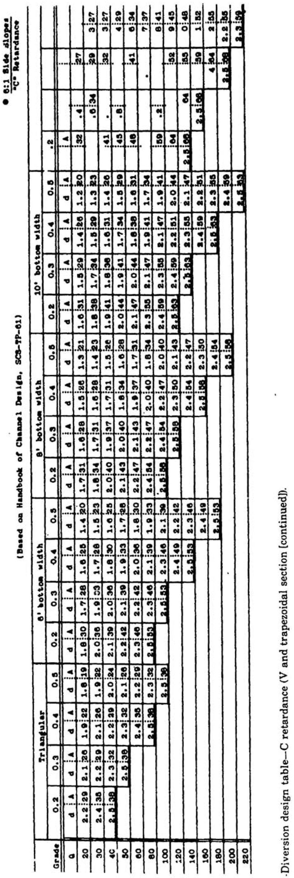
22 Peak flow is obtained based on the frequency of the design storm as required by local standards and using peak flow development procedures. Local site conditions will determine what grade the diversion will have depending on the ground slope and the elevations at the beginning and ending points of the diversion. Vegetative cover expected in the channel will be determined by site conditions and local standards. Cover must be a species that will grow under the conditions and in the soil of the local area. Some local specifications require design velocities based upon bare soil. This requirement would be used where the diversion will flow for long periods or the soil conditions are such that it would be difficult to establish a good vegetation cover. The height that the vegetative cover will be maintained is determined by the species and the maintenance program. Figure 5 is used to determine the retardance factor for the proposed diversion in the same manner as for grassed waterways. Permissible diversion velocities are taken from figure 7. This figure gives velocities based on the soil texture of the soil horizon into which the diversion is excavated, the retardance, and the channel vegetative condition. Permissible velocity for bare channels is also given. Diversions may be designed as parabolic, triangular or trapezoidal channels. The shape will be determined by several factors. The steepness of the slope that the diversion crosses will determine the type. A steep slope requires a narrow, deeper channel where a flatter slope requires wider channels. In agricultural areas, the dimensions should be adapted to farm equipment and maintenance. Available construction equipment will also be a factor in shape. A bulldozer will be able to shape a parabolic channel and a trapezoidal channel that has a bottom width greater than the blade width. A road grader (maintainer) is efficient in shaping V-type channels. Knowing the discharge, retardance, permissible velocity, bottom grade, and shape, the channel can be designed. Design of parabolic channels use figures 8 and 9 (exhibit 9-1, 9-2 EFH). Triangular and trapezoidal channels use figures 10 and 11.
23 Example I-Parabolic Diversion Given Design a diversion channel of parabolic shape to carry 50 cfs at 2 percent grade. Vegetative cover is to be centipedegrass in good condition on sandy clay loam. Solution Design based on C retardance for capacity. Select D retardance for stability of the channel. Permissible velocity = 4 fps (from figure 7) Using figure 8, with Grade = 2 percent, VI = 4.0 and Q = 50 cfs then: T=18.8ft D=1.1ft V2 = 3.5 cfs Example 2-Parabolic Diversion Given Design the channel above when permissible velocity is based on bare ground. Solution V I for bare ground = 2 fps Using Figure 8: T = 61.7 ft D = 0.8 ft V2 = 1.5 fps
24 Generated by a Trial Version of NetCentric Technologies CommonLook Acrobat Plug-in. Example 3- Trapezoidal Channel Given Q = 100 cfs; clay soil; channel grade = 0.4 percent; vegetation will be Bermudagrass maintained at 2.5 in; equipment used will require a 10 foot bottom width and 4: 1 slide slopes. Solution Using retardance 0, V (permissible) = 5 fps (fig. 7). Enter figure lob with 100 cfs, 10 foot BW; 0.4 percent grade; obtain d= 2 ft A= 36 ft Velocity is within a permissible range. If other equipment was used and a triangular shape acceptable, the values would be: d=2.9ft A=34 V=2.94fps
25 Earth or Vegetated Emergency Spillways Principal and Emergency Spillways Pond design usually includes both a principal spillway and emergency spillway. The principal spillway is designed to pass frequent flows without causing the emergency spillway to function. A pond designed for flood protection will have relatively low principal spillway capacity with significant flood pool storage. Ponds designed for other purposes will have a larger principal spillway flow capacity approaching, and sometimes equaling, the peak discharge into the pond. Emergency Spillways Emergency spillways are earth or vegetated earth channels designed to pass flows greater than the principal spillway design. The emergency spillway design peak flow is determined by State Standards and Specifications, but will not be less than the peak generated by the 25-year storm. Earth Spillways The term Earth Spillways applies to both vegetated and non vegetated spillways, although they are usually vegetated. Arid areas and areas with extremely poor soil conditions where it is impossible to maintain suitable cover are places where earth (nonvegetated) spillways would be designed. Earth spillways are usually excavated but may be located in a natural draw, saddle or drainage way. Emergency Spillway Requirements Requirements of an emergency spillway are to pass the design peak flow and discharge it to a point well away from the dam at a velocity that will not cause appreciable erosion. The design peak flow through the emergency spillway may be reduced by the capacity of the principal spillway and the affect of any temporary flood storage provided in the reservoir. Excavated Earth Spillways An excavated earth spillway consists of an approach channel, a control section, and an exit channel (fig. 12). Flow enters the spillway through an approach section. Flow, controlled by the level portion of the approach section, passes through critical depth at the control section (downstream edge of the level portion). Flow discharged through the exit section returns to the natural channel below the dam. The level section is the highest point in the emergency spillway. The approach section must have a grade of at least 2 percent back into the pool and the exit section must have a grade or slope greater than critical slope but less than that which will result in a maximum velocity equal to the permissible velocity.
26 Permissible Exit Channel Velocity Permissible exit channel velocities are determined by the erosive velocities of the material and the vegetation planned. Maximum permissible velocities are given in figure 13 for vegetated spillways, and figure 14 for earthen spillways. Exit channels should be straight and should confine the outflow to a point where water may be released without damage to the fill.
27 Generated by a Trial Version of NetCentric Technologies CommonLook Acrobat Plug-in. veloerosion resistant 31salls -of exit channel pet pet ftls ftls city 21-Easily ersoils of pct0-5ft/s odible il exit channel pct5-10. ftls Bennudagrass Eahiagrass Buffalograss Kentucky bluegrass Smoo th bromegrass Tall fescue Reed Canarygrass Sad forming grass-legume mixtures Lespedeza sericea Weeping lovegrass Yellow bluestem Native grass mixtures /If 1/ SCS-Tl'-61 Increase values 10 percent.when the anticipated average us e of the spillway' 1s not more frequent than Once in 5 years or 25 percent when the anticipated average use is not more frequent than once in 10 years. Those with a higher clay content and higher plasticity. Typical soil textures are silty clay, sandy clay, and clay. Those with a high <content of fine sand r silty and Ij)wer plasticity or non-plastic..typical soil textures are fine sand. silt, sandy loam, and silty loam.. Figure 13. Permissible velocities for vegetated spillways. (Ref.: NRCS, Engineering Field Original material excavated Ft/sec Fine sand, non-colloidal 1.50 Sandy loam, non-colloidal 1.1S Silt loam, non-colloidal 2.00 Alluvial silts, non-colloidal 2.00 Ordinary firm loam 2.50 Volcanic ash 2.50 Fine gravel, 2.50 Stiff clay, very' colloidal Graded, loam to cobbles, non-colloidal Alluvial silts, colloidal 3.15 Graded, silt to cobbles, colloidal 4.00 Coarse gravel, non-colloidal Cobbles and shingles Shales and hardpans From TR No. 60 Earth Dams and Reservoirs, 1/ June / Values shown apply to clear water, no detritus. Figure 14. Permissible velocities for earth spillways. (Ref.: NRCS, Engineering Field Stand Average length of vegetation Degree of retardance Stand Average length of vegetation Degree of retardance Good Longer than to 24 6 to 10 2 to 6 les$ than 2 A B C Ii Fair Longer tha n to 24 6 to 10 2 to 6 less than 2 B C D D Figure 15. Guide to selection of vegetal retardance. (Ref.: NRCS, Engineering Field Handbook, Chapter 11 -Ponds and Reservoirs, p a.)
28 Generated by a Trial Version of NetCentric Technologies CommonLook Acrobat Plug-in. Retardance A (English Units) Max. Velocity Discharge Hp Slope Range V q L(ft) Min. Max ft/s ft.3/s/ft ft ft ft ft pet : Figure 16a. H and slope range for discharge, velocity, and crest length; Retardance A. (Ref.: NRCS, Engineering Field Handbook, Chapter 11-Ponds and Reservoirs, p f.) Retardance 'B (English Units) Max. Velocity' Discharge IIp Slope Range V q L(ft) Min. Max ft{s ft3/s/,ft ft. ft ft ft pet Figure 16b. H'E and slope range for discharge, velocity, and crest length; Retardance B. (Ref.: NRCS, engineering Field Handbook, Chapter 11-Ponds and Reservoirs, p g.)
29 Generated by a Trial Version of NetCentric Technologies CommonLook Acrobat Plug-in. Retardate C (English Units) Max. Velocity Discharge Hp Slope Range V q L(ft) Min. Max ft/s ft3/s/ft ft ft ft ft pet " Figure 16c. H and slope range for discharge, velocity, and crest length; Retardance C. (Ref.: NRCS, 'Engineering Field Handbook, Chapter 11-ponds and Reservoirs, p h.) Retard3.nce D (English Units) Max. Velocity ltisc;harge Hp Slope Range V q L(ft) Min.Max " ft/s tt3/sift ft ft ft ft pet i Figure 16d. HI!- and slope range for discharge, velocity, and crest length; Retardance D. (Ref.: NRCS, t:ngineering Field Handbook, Chapter 11-Ponds and Reservoirs, p i.)
30 Retardance E (English Units) Max. Velocity Discharge IIp Slope Range V q L(ft) Min. Max ft/s ft3/s/ftft ft ft ft pet ' figure 16e. He and slope range for discharge, velocity, and crest length; Retardance E. (Ref.: NRCS, Engineering Field Handbook, Chapter 11-Ponds and Reservoirs, p j.) Generated by a Trial Version of NetCentric Technologies CommonLook Acrobat Plug-in.
31 Vegetal Retardance The degree of retardance in a spillway depends primarily on the height and density of the selected vegetation. Figure 15 gives retardance classes for varying vegetation conditions. Retardance class E is used for earth spillways. The retardance class for a good uncut condition is generally used for capacity determination, and a lower degree of retardance representing the establishment period and after-mowing condition is advised for stability design. Design of Vegetated Spillways Designers of vegetated spillways use the tables shown in figures 16a-e. These tables are not appropriate for bottom widths less than.g ft., and the bottom width should not exceed 35 times the design depth of flow. Spillway side slopes should be no steeper than 3: 1. Use these tables with a given velocity, crest length, and exit channel slope to determine unit width discharge and reservoir stage. Bottom width is then calculated as: where: 8 b = bottom width (ft) Q = discharge (cfs) q = unit width discharge (cfs/ft)
32 Example 1 Determine bottom width and reservoir stage with the following Given Q = 180 cfs L = 50 ft Exit slope = 2.9 percent Erosion resistant soil planted to Kentucky bluegrass with good stand averaging 6 to 10 inches height expected. Solution Permissible velocity for erosion resistant soil, Kentucky bluegrass, and exit slope = 2.9% is 7 ft/s (figure 13). Retardance for stability with good stand of vegetation 2 to 6 inches is D (figure 15). Retardance for capacity with good stand of vegetation 6 to 10 inches is C (figure 15). From figure 16d, select maximum velocity = 7 ft/s and choose the slope range 1 to 4 percent as best fit. Then read discharge q = 4 /sec/ft and calculate: / =45ft (stability) / / From figure 16c, enter with q = 4 ft3/sec/ft and read Hp for L of 50 ft; Hp = 1.6 ft (capacity)
33 Example 2 Determine bottom width and stage for the following: Given Q = 48 cfs L = 25 ft Exit slope = 3.5 percent Very erosive soil planted to bermudagrass with fair stand aver aging 11 to 24 inches height expected. Solution Permissible velocity for very erosive soil, bermudagrass, and exit slope of 3.5 percent is 6 ft/s (figure 13). Retardance for stability with fair stand less than 2 inches is E (figure 15). Retardance for capacity with fair stand 11 to 24 inches is C (figure 15). From figure 16e, select maximum velocity = 6 ft/s and choose the slope range 1 to 4 percent as best fit. Then read discharge q = 3 ft/sec/ft and calculate: 48 / 3 / 16
34 Alternative Spillways When the trial layout does not meet the criteria in the above tables, alternate systems should be considered. Listed are some alternate systems. Change exit slope. This may result in a need for wing or kicker dikes or excess excavation. Raise the crest of the control section. This gives some flood storage and reduces the peak flow. Locate a second spillway on the opposite side of dam. Try another type of spillway (i.e., concrete, riprap). Natural Spillways Whenever a dam is being planned, consideration should be given to the use of a natural emergency spillway. Many sites have natural saddles which can be used to safely convey flow around the dam. Use of a natural spillway reduces construction costs and maintenance is easier since both the natural surface and vegetation will not be disturbed. Discharge Capacity The shape of the spillway control section is usually V-shaped with one side being determined by the embankment end and the other by natural ground. Figure 17 shows a typical profile and cross section of a natural spillway. The end of the dam should be approximately perpendicular to the contours of the abutment.
35 Generated by a Trial Version of NetCentric Technologies CommonLook Acrobat Plug-in. Natural Figure 18 is used to determine the velocity (v) and depth of water in the reservoir above the crest (Hp) for a given discharge. Retardanee Ground A B C D E Slope Slope 2 Hp Q V Q V Q V Q V Q V Min. Max. pet ft ft31s ft/s ft3/s ft/s ft3/s ft/s ft3/s ft/s ft3/s ft/s pc't S S ' ' S S IS Figure 18. Discharge through natural vegetated spillways with 3:1 end slope. (Ref.: NRCS Engineering Field Handbook, Chapter 11-Ponds and Reservoirs, p b.)
36 Design of Natural Spillways The required inputs for natural spillway design are the required discharge capacity, vegetal retardance, the end slope of the embankment (21) and the slope of the natural ground (22), Figure 18 was developed for an end slope of 3: 1, and natural ground slopes from 1 to 5 percent. The velocity and H can be read p from figure 18 for the appropriate combination of retardance, Q, and 22, Hp can be determined by interpolation when necessary. Example 1 Find V and Hp for a natural vegetative spillway at the end of the embankment. Given = 3: 1 = 2 percent Q = 190 cfs Vegetation: Bermudagrass, good stand Height: 6 to 10 inches Solution From figure 15, determine a retardance class of C. In figure 18, enter with 22 = 1%, and under retardance C column, find Q = 190 cfs with V = 5.4 ft/s and Hp = 2.0 ft This velocity is below the maximum permissible velocity of 8 ft! (given in figure 13 for erosion resistant soils.) Example 2 Find V and H P. Given = 3:1 = 3 percent Q = 70 cfs Vegetation: Tall fescue, good stand Height: 11 to 24 inches Generated by a Trial Version of NetCentric Technologies CommonLook Acrobat Plug-in.
37 Generated by a Trial Version of NetCentric Technologies CommonLook Acrobat Plug-in. Solution From figure 15, determine a retardance class of B. In figure 18, enter with 22 = 3% and under retardance class B column, look for Q = 70 cfs. Interpolation is required between Q = 57 cfs and Q = 81 cfs. The velocities at these discharges are 3.0 and 3.7 ft/s, respectively. Therefore, V for Q = 70 cfs is: = = 3.4 ft/s Similarly, is calculated by:... H -1.8 = ft
38 Generated by a Trial Version of NetCentric Technologies CommonLook Acrobat Plug-in. Summary Now that you have completed Module 112, you should be able to use the stage discharge relationship factors and Manning's equation. You should also be familiar with procedures for sizing drainage ditches, grassed waterways, diversions, and earth emergency spillways for simple, small applications. The methods described in this module are described and used in the Engineering Field Handbook (EFH) where additional tables may be found. Additional study of the chapters in the EFH would give a fuller understanding of this material. Retain this Study Guide as a reference until you are satisfied that you have successfully mastered all the methods covered. It will provide an easy review at any time if you should encounter a problem. If you have had problems understanding the module or if you would like to take additional, related modules, contact your supervisor. When you are satisfied that you have completed this module, remove the Certification of Completion sheet (last page of the Study Guide), fill it out, and give it to your supervisor to submit, through channels, to your State Training Officer.
39 Activity 1 At this time, complete Activity 1 in your Study Guide to review the material just covered. After finishing the activity, compare your answers with the solution. When you are satisfied that you understand the material, continue with the Study Guide text. 1. List three factors that cause variation in discharge at a point. a. b. c. 2. List two conditions that describe critical flow. a. b. 3. A channel has an area = 54 sq. ft. and a top width of 30 feet. Determine the critical flow. 4. List four channel factors that affect the flow conditions. a. b. c. d.
40 Generated by a Trial Version of NetCentric Technologies CommonLook Acrobat Plug-in Determine a, p, r, d, T and dm for the following channel 6. Determine a, p, r, d, T and dm for the following channel: 7. When do downstream conditions affect the flow at a cross-section?
41 Generated by a Trial Version of NetCentric Technologies CommonLook Acrobat Plug-in. Activity 2 At this time, complete Activity 2 in your Study Guide to review the material just covered. After finishing the Activity, compare your answers with the solution provided. When you are satisfied that you understand the material, continue with the Study Guide text. 1. List five factors that are considerations in developing roughness coefficient - n. a. b. c. d. e. 2. Determine a, p, r, d, T and dm for the following channel. Determine the velocity and flow in this channel. S = ft/ft, channel is clean, straight with considerable amount of weeds and stones.
CHAPTER 5 OPEN CHANNEL HYDROLOGY
 5.4 Uniform Flow Calculations 5.4.1 Design Charts CHAPTER 5 OPEN CHANNEL HYDROLOGY Following is a discussion of the equations that can be used for the design and analysis of open channel flow. The Federal
Open Channel Flow 2F-2. A. Introduction. B. Definitions. Design Manual Chapter 2 - Stormwater 2F - Open Channel Flow
 Design Manual Chapter 2 - Stormwater 2F - Open Channel Flow 2F-2 Open Channel Flow A. Introduction The beginning of any channel design or modification is to understand the hydraulics of the stream. The
CITY UTILITIES DESIGN STANDARDS MANUAL
 CITY UTILITIES DESIGN STANDARDS MANUAL Book 2 (SW) SW9 June 2015 SW9.01 Purpose This Chapter provides information for the design of open channels for the conveyance of stormwater in the City of Fort Wayne.
Channel Stabilization with Basic Flow Calculations
 Channel Stabilization with Basic Flow Calculations Description Selection Criteria The selection of a channel lining will greatly influence how a drainage channel performs, the amount of erosion and scour,
2O-1 Channel Types and Structures
 Iowa Stormwater Management Manual O-1 O-1 Channel Types and Structures A. Introduction The flow of water in an open channel is a common event in Iowa, whether in a natural channel or an artificial channel.
Travel Time. Computation of travel time and time of concentration. Factors affecting time of concentration. Surface roughness
 3 Chapter 3 of Concentration and Travel Time Time of Concentration and Travel Time Travel time ( T t ) is the time it takes water to travel from one location to another in a watershed. T t is a component
2.0 BASIC CONCEPTS OF OPEN CHANNEL FLOW MEASUREMENT
 2.0 BASIC CONCEPTS OF OPEN CHANNEL FLOW MEASUREMENT Open channel flow is defined as flow in any channel where the liquid flows with a free surface. Open channel flow is not under pressure; gravity is the
Index. protection. excavated drop inlet protection (Temporary) 6.50.1 6.51.1. Block and gravel inlet Protection (Temporary) 6.52.1
 6.50.1 6.51.1. Block and gravel inlet Protection (Temporary) 6.52.1") 6 Index inlet protection excavated drop inlet protection (Temporary) 6.50.1 HARDWARE CLOTH AND GRAVEL INLET PROTECTION Block and gravel inlet Protection (Temporary) sod drop inlet protection ROCK DOUGHNUT
6 Index inlet protection excavated drop inlet protection (Temporary) 6.50.1 HARDWARE CLOTH AND GRAVEL INLET PROTECTION Block and gravel inlet Protection (Temporary) sod drop inlet protection ROCK DOUGHNUT
Basic Hydrology. Time of Concentration Methodology
 Basic Hydrology Time of Concentration Methodology By: Paul Schiariti, P.E., CPESC Mercer County Soil Conservation District What is the Time of Concentration? The time it takes for runoff to travel from
Outlet stabilization structure
 Overview of Sedimentation and Erosion Control Practices Practice no. 6.41 Outlet stabilization structure Erosion at the outlet of channels, culverts, and other structures is common, and can cause structural
Land Disturbance, Erosion Control and Stormwater Management Checklist. Walworth County Land Conservation Department
 Land Disturbance, Erosion Control and Stormwater Management Checklist Walworth County Land Conservation Department The following checklist is designed to assist the applicant in complying with the Walworth
Design Charts for Open-Channel Flow HDS 3 August 1961
 Design Charts for Open-Channel Flow HDS 3 August 1961 Welcome to HDS 3-Design Charts for Open-Channel Flow Table of Contents Preface DISCLAIMER: During the editing of this manual for conversion to an electronic
Riprap-lined Swale (RS)
") Riprap-lined Swale (RS) Practice Description A riprap-lined swale is a natural or constructed channel with an erosion-resistant rock lining designed to carry concentrated runoff to a stable outlet. This
Riprap-lined Swale (RS) Practice Description A riprap-lined swale is a natural or constructed channel with an erosion-resistant rock lining designed to carry concentrated runoff to a stable outlet. This
Topic 8: Open Channel Flow
 3.1 Course Number: CE 365K Course Title: Hydraulic Engineering Design Course Instructor: R.J. Charbeneau Subject: Open Channel Hydraulics Topics Covered: 8. Open Channel Flow and Manning Equation 9. Energy,
NJ650.1404 Interception Drainage
 NJ650.1404 Interception Drainage Interception drainage is used to intercept surface and subsurface water. The investigation, planning, and construction of surface interception drains follow the requirements
Emergency Spillways (Sediment basins)
") Emergency Spillways (Sediment basins) DRAINAGE CONTROL TECHNIQUE Low Gradient Velocity Control Short-Term Steep Gradient Channel Lining Medium-Long Term Outlet Control Soil Treatment Permanent [1] [1]
Emergency Spillways (Sediment basins) DRAINAGE CONTROL TECHNIQUE Low Gradient Velocity Control Short-Term Steep Gradient Channel Lining Medium-Long Term Outlet Control Soil Treatment Permanent [1] [1]
STATE OF FLORIDA DEPARTMENT OF TRANSPORTATION DRAINAGE HANDBOOK OPEN CHANNEL. OFFICE OF DESIGN, DRAINAGE SECTION November 2009 TALLAHASSEE, FLORIDA
 STATE OF FLORIDA DEPARTMENT OF TRANSPORTATION DRAINAGE HANDBOOK OPEN CHANNEL OFFICE OF DESIGN, DRAINAGE SECTION TALLAHASSEE, FLORIDA Table of Contents Open Channel Handbook Chapter 1 Introduction... 1
Open Channel Flow in Aquaculture
 SRAC Publication No. 74 Southern Regional Aquaculture Center March 1995 PR VI Open Channel Flow in Aquaculture J. David Bankston, Jr. 1 and Fred Eugene Baker Open channel flow of water has been used in
Chapter 3 CULVERTS. Description. Importance to Maintenance & Water Quality. Culvert Profile
 Chapter 3 CULVERTS Description A culvert is a closed conduit used to convey water from one area to another, usually from one side of a road to the other side. Importance to Maintenance & Water Quality
Appendix 4-C. Open Channel Theory
 4-C-1 Appendix 4-C Open Channel Theory 4-C-2 Appendix 4.C - Table of Contents 4.C.1 Open Channel Flow Theory 4-C-3 4.C.2 Concepts 4-C-3 4.C.2.1 Specific Energy 4-C-3 4.C.2.2 Velocity Distribution Coefficient
CHAPTER 9 CHANNELS APPENDIX A. Hydraulic Design Equations for Open Channel Flow
 CHAPTER 9 CHANNELS APPENDIX A Hydraulic Design Equations for Open Channel Flow SEPTEMBER 2009 CHAPTER 9 APPENDIX A Hydraulic Design Equations for Open Channel Flow Introduction The Equations presented
MODULE 3 OPEN CHANNEL DESIGN. Wetted parameter Cross-sectional area. Introduction
 MODULE 3 OPEN CHANNEL DESIGN Introduction An open channel is defined as any conveyance system where a liquid is moved under the influence of gravity in the presence of an air-water interface. Open channel
What is the most obvious difference between pipe flow and open channel flow????????????? (in terms of flow conditions and energy situation)
") OPEN CHANNEL FLOW 1 3 Question What is the most obvious difference between pipe flow and open channel flow????????????? (in terms of flow conditions and energy situation) Typical open channel shapes Figure
OPEN CHANNEL FLOW 1 3 Question What is the most obvious difference between pipe flow and open channel flow????????????? (in terms of flow conditions and energy situation) Typical open channel shapes Figure
3. Design Procedures. Design Procedures. Introduction
 Design Procedures 3. Design Procedures Introduction This chapter presents a procedure for the design of natural channels. The chapter primarily focuses on those physical properties of the channel required
CHAPTER 3 STORM DRAINAGE SYSTEMS
 CHAPTER 3 STORM DRAINAGE SYSTEMS 3.7 Storm Drains 3.7.1 Introduction After the tentative locations of inlets, drain pipes, and outfalls with tail-waters have been determined and the inlets sized, the next
City of Shelbyville Site Inspection Checklist
 City of Shelbyville Site Inspection Checklist General Information Project Name: KYR10 Permit Number: Date: Project Location: Contractor: Conractor Representative: Inspector's Name: Title: Signature : Weather
Table 4.9 Storm Drain Inlet Protetion Applicable for
 BMP C220: Storm Drain Inlet Protection Purpose To prevent coarse sediment from entering drainage systems prior to permanent stabilization of the disturbed area. Conditions of Use Type of Inlet Protection
Rational Method Hydrologic Calculations with Excel. Rational Method Hydrologic Calculations with Excel, Course #508. Presented by:
 Rational Method Hydrologic Calculations with Excel, Course #508 Presented by: PDH Enterprises, LLC PO Box 942 Morrisville, NC 27560 www.pdhsite.com Calculation of peak storm water runoff rate from a drainage
URBAN DRAINAGE CRITERIA
 URBAN DRAINAGE CRITERIA I. Introduction This division contains guidelines for drainage system design and establishes a policy for recognized and established engineering design of storm drain facilities
Construction Site Inspection Checklist for OHC000004 By making use of some simple Best Management Practices (BMPs) a construction site operator can
 a construction site operator can") Construction Site Inspection Checklist for OHC000004 By making use of some simple Best Management Practices (BMPs) a construction site operator can do his or her share to protect Ohio's water resources
Construction Site Inspection Checklist for OHC000004 By making use of some simple Best Management Practices (BMPs) a construction site operator can do his or her share to protect Ohio's water resources
Chapter 9. Steady Flow in Open channels
 Chapter 9 Steady Flow in Open channels Objectives Be able to define uniform open channel flow Solve uniform open channel flow using the Manning Equation 9.1 Uniform Flow in Open Channel Open-channel flows
Prattsville Berm Removal Project. 1.0 Project Location
 Prattsville Berm Removal Project 1.0 Project Location The project site is located between the New York State Route 23 Bridge over the Schoharie Creek and the Schoharie Reservoir. The restoration plan encompassed
Experiment (13): Flow channel
: Flow channel") Introduction: An open channel is a duct in which the liquid flows with a free surface exposed to atmospheric pressure. Along the length of the duct, the pressure at the surface is therefore constant and
Introduction: An open channel is a duct in which the liquid flows with a free surface exposed to atmospheric pressure. Along the length of the duct, the pressure at the surface is therefore constant and
A perforated conduit such as pipe, tubing or tile installed beneath the ground to intercept and convey ground water. or structures.
 BMP: SUBSURFACE DRAIN Definition A perforated conduit such as pipe, tubing or tile installed beneath the ground to intercept and convey ground water. PurRoses 1. To prevent sloping soils from becoming
Storm Drainage Systems 11.9-1
 Storm Drainage Systems 11.9-1 11.9 Gutter Flow Calculations 11.9.1 Introduction Gutter flow calculations are necessary in order to relate the quantity of flow (Q) in the curbed channel to the spread of
CHAPTER 3A Environmental Guidelines for STREAM CROSSING BY ALL-TERRAIN VEHICLES
 GOVERNMENT OF NEWFOUNDLAND AND LABRADOR DEPARTMENT OF ENVIRONMENT AND LABOUR CHAPTER 3A Environmental Guidelines for STREAM CROSSING BY ALL-TERRAIN VEHICLES WATER RESOURCES MANAGEMENT DIVISION Water Investigations
CHAPTER 860 OPEN CHANNELS
 HIGHWAY DESIGN MANUAL 860-1 CHAPTER 860 OPEN CHANNELS Topic 861 - General Index 861.1 - Introduction An open channel is a conveyance in which water flows with a free surface. Although closed conduits such
RIPRAP From Massachusetts Erosion and Sediment Control Guidelines for Urban and Suburban Areas http://www.mass.gov/dep/water/laws/policies.
 RIPRAP From Massachusetts Erosion and Sediment Control Guidelines for Urban and Suburban Areas http://www.mass.gov/dep/water/laws/policies.htm#storm Definition: A permanent, erosion-resistant ground cover
M6a: Open Channel Flow (Manning s Equation, Partially Flowing Pipes, and Specific Energy)
") M6a: Open Channel Flow (, Partially Flowing Pipes, and Specific Energy) Steady Non-Uniform Flow in an Open Channel Robert Pitt University of Alabama and Shirley Clark Penn State - Harrisburg Continuity
M6a: Open Channel Flow (, Partially Flowing Pipes, and Specific Energy) Steady Non-Uniform Flow in an Open Channel Robert Pitt University of Alabama and Shirley Clark Penn State - Harrisburg Continuity
Block and Gravel Inlet Protection (BIP)
") Block and Gravel Inlet Protection (BIP) Practice Description Block and gravel inlet protection is a sediment control barrier formed around a storm drain inlet by the use of standard concrete block and
Block and Gravel Inlet Protection (BIP) Practice Description Block and gravel inlet protection is a sediment control barrier formed around a storm drain inlet by the use of standard concrete block and
TENNESSEE GAS PIPELINE COMPANY, L.L.C.
 TENNESSEE GAS PIPELINE COMPANY, L.L.C. HYDROLOGIC & HYDRAULIC CALCULATIONS FOR WATERBODIES CROSSED BY CONNECTICUT PIPELINE EXPANSION PROJECT CONNECTICUT LOOP Submitted by: Tennessee Gas Pipeline Company,
Flash Flood Science. Chapter 2. What Is in This Chapter? Flash Flood Processes
 Chapter 2 Flash Flood Science A flash flood is generally defined as a rapid onset flood of short duration with a relatively high peak discharge (World Meteorological Organization). The American Meteorological
CHAPTER 2 HYDRAULICS OF SEWERS
 CHAPTER 2 HYDRAULICS OF SEWERS SANITARY SEWERS The hydraulic design procedure for sewers requires: 1. Determination of Sewer System Type 2. Determination of Design Flow 3. Selection of Pipe Size 4. Determination
STORM DRAINS CHAPTER 7
 CHAPTER 7 Chapter 7 - Storm Drains A storm drain is a drainage system that conveys water or stormwater, consisting of two or more pipes in a series connected by one or more structures. Storm drains collect
STANDARD AND SPECIFICATIONS FOR STORM DRAIN INLET PROTECTION
 STANDARD AND SPECIFICATIONS FOR STORM DRAIN INLET PROTECTION Design Criteria Drainage Area The drainage area for storm drain inlets shall not exceed one acre. The crest elevations of these practices shall
SECTION 5 - STORM DRAINS
 Drainage Criteria Manual SECTION 5 - STORM DRAINS 5.1.0 GENERAL This The purpose of this section discusses briefly is to consider the hydraulic aspects of storm drains and their appurtenances in a storm
ESTIMATING DISCHARGE AND STREAM FLOWS
 ESTIMATING DISCHARGE AND STREAM FLOWS A Guide for Sand and Gravel Operators Prepared by: Joy P. Michaud and Marlies Wierenga, EnviroVision Art and design by: S. Noel, Noel Design, LLC July 2005 Ecology
Small Dam Hazard Assessment Inventory
 Small Dam Hazard Assessment Inventory What would happen if your dam were to fail? This is a question that most dam owners hope they will never have to answer. However it is a question you, as a responsible
Open channel flow Basic principle
 Open channel flow Basic principle INTRODUCTION Flow in rivers, irrigation canals, drainage ditches and aqueducts are some examples for open channel flow. These flows occur with a free surface and the pressure
STORMWATER MANAGEMENT CHECKLIST
 STORMWATER MANAGEMENT CHECKLIST *This checklist must be completed and part of the Land Disturbing Permit submittal for review if the acreage disturbed is one (1) acre or more: I. SUPPORTING DATA Narrative
1. Carry water under the canal 2. Carry water over the canal 3. Carry water into the canal
 Lecture 21 Culvert Design & Analysis Much of the following is based on the USBR publication: Design of Small Canal Structures (1978) I. Cross-Drainage Structures Cross-drainage is required when a canal
SE-10 STORM DRAIN INLET PROTECTION. Objectives
 STORM DRAIN INLET PROTECTION SE-10 Objectives Erosion Control - EC Sediment Control - SE Tracking Control - TC Wind Erosion Control - WE Non-Storm Water Management - NS Waste and Materials Management -
Storm Drain Inlet Protection
 Objectives EC Erosion Control SE Sediment Control TR Tracking Control WE Wind Erosion Control Non-Stormwater NS Management Control Waste Management and WM Materials Pollution Control Legend: Primary Objective
CHAPTER 4 STORM DRAINAGE SYSTEMS
 CHAPTER 4 STORM DRAINAGE SYSTEMS 4.1 Overview... 4-1 4.1.1 Introduction... 4-1 4.1.2 Inlet Definition... 4-1 4.1.3 Criteria... 4-1 4.2 Pavement Drainage... 4-2 4.2.1 Introduction... 4-2 4.2.2 Storm Drain
BRIDGES ARE relatively expensive but often are
 Chapter 10 Bridges Chapter 10 Bridges Bridg Bridges -- usually the best, but most expensive drainage crossing structure. Protect bridges against scour. BRIDGES ARE relatively expensive but often are the
How To Check For Scour At A Bridge
 Case Studies Bridge Scour Inspection and Repair Edward P. Foltyn, P.E. Senior Hydraulic Engineer ODOT Bridge Unit 2013 PNW Bridge Inspectors Conference April 2013 REFERENCES Stream Stability at Highway
Storm Drain Inlet Protection - IP
 Storm Drain Inlet Protection - IP DEFINITION A temporary protective device formed around a storm drain drop inlet to trap sediment. PURPOSE To prevent sediment from entering storm drainage systems, prior
APPLICATION PROCESS FOR LAND DISTURBING PERMIT
 PREFACE: APPLICATION PROCESS FOR LAND DISTURBING PERMIT The property owner, developer and designated planners and engineers shall review the general development plans and detailed plans of the Local Issuing
ARTICLE II STORM DRAINAGE. (From Ordinance No. 1987-17; August 4, 1987; Sections III through VIII)
") ARTICLE II STORM DRAINAGE (From Ordinance No. 1987-17; August 4, 1987; Sections III through VIII) SECTION 2.1 Standard Provisions Standard Provisions All construction for storm drainage in the development
ARTICLE II STORM DRAINAGE (From Ordinance No. 1987-17; August 4, 1987; Sections III through VIII) SECTION 2.1 Standard Provisions Standard Provisions All construction for storm drainage in the development
Lecture 24 Flumes & Channel Transitions. I. General Characteristics of Flumes. Flumes are often used:
 Lecture 24 Flumes & Channel Transitions I. General Characteristics of Flumes Flumes are often used: 1. Along contours of steep slopes where minimal excavation is desired 2. On flat terrain where it is
Chapter 13 OPEN-CHANNEL FLOW
 Fluid Mechanics: Fundamentals and Applications, 2nd Edition Yunus A. Cengel, John M. Cimbala McGraw-Hill, 2010 Lecture slides by Mehmet Kanoglu Copyright The McGraw-Hill Companies, Inc. Permission required
SUSTAINABLE URBAN DRAINAGE SYSTEMS
 overflow can lead into a permeable conveyance system to increase further the benefit and reduce the need for pipe systems. Pollutant removal rates have been shown to be high, with some pollutants being
CHAPTER 5 HYDROLOGIC ANALYSIS AND DESIGN
 CHAPTER 5 HYDROLOGIC ANALYSIS AND DESIGN Chapter Organization 5.1 Introduction... 5-1 5.2 Hydrologic Analysis Methods... 5-1 5.3 Curve Number Method... 5-2 5.3.1 NRCS Curve Number Method Theory... 5-2
Watershed Works Manual
 National Rural Employment Guarantee Act Watershed Works Manual DRAINAGE LINE TREATMENT: GABION STRUCTURE Baba Amte Centre for People s Empowerment Samaj Pragati Sahayog September 2006 Drainage Line Treatment:
CHAPTER 5. Storm Sewer
 CHAPTER 5 Storm Sewer A. Introduction All proposed developments shall have a properly designed and constructed storm water conveyance system. This chapter deals only with the conveyance system. Storm water
APPENDIX B DESIGN GUIDELINES FOR APPROVED TREATMENT METHODS
 APPENDIX B DESIGN GUIDELINES FOR APPROVED TREATMENT METHODS PLANTER BOXES 1. Determine the impervious area contributing flow to the planter box (see Chapter 4.2). 2. Assumption: Typical soil infiltration
Stream Rehabilitation Concepts, Guidelines and Examples. Objectives. Pierre Y. Julien. Three Laws of Stream Restoration
 Stream Rehabilitation Concepts, Guidelines and Examples Pierre Y. Julien Wuhan 2005 Objectives Part I - Stream restoration and rehabilitation: 1. Present and discuss important concepts, laws, criteria
CLIFTY CREEK PLANT MADISON, INDIANA
 2015 DAM AND DIKE INSPECTION REPORT GERS-15-018 CLIFTY CREEK PLANT MADISON, INDIANA PREPARED BY GEOTECHNICAL ENGINEERING AEP SERVICE CORPORATION 1 RIVERSIDE PLAZA COLUMBUS, OHIO Annual Dam and Dike Inspection
Rural Flooding: The Potential Role of Forestry
 Rural Flooding: The Potential Role of Forestry Nadeem Shah, Tom Nisbet, & Huw Thomas Centre for Forestry and Climate Change Structure Background Woodland and Flood Alleviation The Theory. Studies on Woodland
SECTION 5. Sediment Control Measures
 SECTION 5 Sediment Control Measures 60. STORM DRAIN INLET PROTECTION When Runoff from earth change activities will discharge to a catch basin or storm drain inlet. A newly constructed catch basin or storm
Chapter 7 Ditches and Channels
 Chapter 7 Ditches and Channels TABLE OF CONTENTS CHAPTER 7 - DITCHES AND CHANNELS... 7-1 7.1 Introduction... 7-1 7.2 Design Policy... 7-2 7.2.1 Federal Policy... 7-2 7.2.2 Commonwealth of Virginia Policy...
Hydraulic Jumps and Non-uniform Open Channel Flow, Course #507. Presented by: PDH Enterprises, LLC PO Box 942 Morrisville, NC 27560 www.pdhsite.
 Hydraulic Jumps and Non-uniform Open Channel Flow, Course #507 Presented by: PDH Enterprises, LLC PO Box 942 Morrisville, NC 27560 www.pdhsite.com Many examples of open channel flow can be approximated
Stormwater/Wetland Pond Construction Inspection Checklist
 : Construction Inspection ChecklistsTools Stormwater/Wetland Pond Construction Inspection Checklist Project: Location: Site Status: Date: Time: Inspector: SATISFACTORY/ UNSATISFACTORY COMMENTS Pre-Construction/Materials
Note: first and second stops will be reversed. Bring clothing and shoes suitable for walking on rough ground.
 Open Channel Page 1 Intro check on laboratory results Field Trip Note: first and second stops will be reversed Irrigation and Drainage Field Trip Bring clothing and shoes suitable for walking on rough
Minimizes sediment and debris from entering storm drains that lead to waterways and watercourses.
 4.5-p DRAIN INLET PROTECTION Alternative Names: DI protection, Drop Inlet Protection DESCRIPTION Storm drain inlet (DI) protection slows and ponds stormwater, and filters sediment and debris before it
Guo, James C.Y. (2004). Design of Urban Channel Drop Structure, J. of Flood Hazards News, December,
. Design of Urban Channel Drop Structure, J. of Flood Hazards News, December,") Guo, James C.. (004). esign of Urban Channel rop Structure, J. of Flood azards News, ecember, Guo, James C.., (009) Grade Control for Urban Channel esign, submitted to Elsevier Science, J. of ydro-environmental
Guo, James C.. (004). esign of Urban Channel rop Structure, J. of Flood azards News, ecember, Guo, James C.., (009) Grade Control for Urban Channel esign, submitted to Elsevier Science, J. of ydro-environmental
Module 9: Basics of Pumps and Hydraulics Instructor Guide
 Module 9: Basics of Pumps and Hydraulics Instructor Guide Activities for Unit 1 Basic Hydraulics Activity 1.1: Convert 45 psi to feet of head. 45 psis x 1 ft. = 103.8 ft 0.433 psi Activity 1.2: Determine
General Permit for Activities Promoting Waterway - Floodplain Connectivity [working title]
![General Permit for Activities Promoting Waterway - Floodplain Connectivity [working title]](/thumbs/39/18645965.jpg "General Permit for Activities Promoting Waterway - Floodplain Connectivity [working title]") General Permit for Activities Promoting Waterway - Floodplain Connectivity [working title] Purpose These rules set forth the conditions under which a person may, without an individual removal-fill permit
General Permit for Activities Promoting Waterway - Floodplain Connectivity [working title] Purpose These rules set forth the conditions under which a person may, without an individual removal-fill permit
BMP-7. A sediment filter or an excavated impounding area around a storm drain drop inlet or curb inlet.
 BMP-7 BMP: STORM DRAIN INLET PROTECTION Definition A sediment filter or an excavated impounding area around a storm drain drop inlet or curb inlet. To prevent sediment from entering storm drainage systems
CONTENTS Channels. 1 Introduction... 7.1
 CONTENTS Channels Introduction... 7. Flow classification... 7.. Steady uniform flow... 7.. Unsteady non-uniform flow... 7.. Unsteady uniform flow... 7. Laminar and turbulent flow... 7. 4 Flow equations...
Hydraulics Prof. A. K. Sarma Department of Civil Engineering Indian Institute of Technology, Guwahati. Module No. # 02 Uniform Flow Lecture No.
 Hydraulics Prof. A. K. Sarma Department of Civil Engineering Indian Institute of Technology, Guwahati Module No. # 02 Uniform Flow Lecture No. # 04 Computation of Uniform Flow (Part 02) Welcome to this
Shooks Run Drainage Study Basic Terminology
 Shooks Run Drainage Study Basic Terminology PREPARED FOR: PREPARED BY: City of Colorado Springs CH2M DATE: April 9, 2015 Introduction This document is intended to provide an introduction to Colorado Springs
CHAPTER 7 DRAINAGE OF PAVEMENTS
 CHAPTER 7 DRAINAGE OF PAVEMENTS 7-1. Drainage control Adequate drainage of surface and ground water is one of the most important considerations in the design, construction, and maintenance of roads, railroads,
1.7.0 Floodplain Modification Criteria
 1.7.0 Floodplain Modification Criteria 1.7.1 Introduction These guidelines set out standards for evaluating and processing proposed modifications of the 100- year floodplain with the following objectives:
SECTION 5: SANITARY SEWER SYSTEM DESIGN
 SECTION 5: SANITARY SEWER SYSTEM DESIGN 5.01 GENERAL Sanitary sewer improvements shall be designed to serve the ultimate level of City development as defined in the General Plan and the Wastewater Facilities
Stormwater Drainage Design for Parking Lots
 PDHonline Course C201 (4 PDH) Stormwater Drainage Design for Parking Lots 2012 PDH Online PDH Center 5272 Meadow Estates Drive Fairfax, VA 22030-6658 Phone & Fax: 703-988-0088 www.pdhonline.org www.pdhcenter.com
Guidelines for Control of Water Runoff on Small Lots. Revised 6/09
 Guidelines for Control of Water Runoff on Small Lots Revised 6/09 Table of Contents Introduction and Purpose 3 Administrative Procedures 3 Plan Submittal Requirements 3 General Design Criteria 4 Dry Wells
Crossing creeks Stream crossings on farms
 Crossing creeks Stream crossings on farms Looking after all our water needs Crossing creeks Stream crossings on farms Looking after all our water needs Department of Water 168 St Georges Terrace Perth
NATURAL RESOURCES CONSERVATION SERVICE CONSERVATION PRACTICE STANDARD SUBSURFACE DRAIN. (Ft.) CODE 606
 CODE 606") 606-1 NATURAL RESOURCES CONSERVATION SERVICE CONSERVATION PRACTICE STANDARD SUBSURFACE DRAIN (Ft.) CODE 606 DEFINITION A conduit installed beneath the ground surface to collect and/or convey excess water.
606-1 NATURAL RESOURCES CONSERVATION SERVICE CONSERVATION PRACTICE STANDARD SUBSURFACE DRAIN (Ft.) CODE 606 DEFINITION A conduit installed beneath the ground surface to collect and/or convey excess water.
Sample DEQ Plan Submitter s Checklist for Stormwater Management Plans
 APPENDIX IV Version: February 2, 2015 Sample DEQ Plan Submitter s Checklist for Stormwater Management Plans Please fill in all blanks and please reference the plan sheets/pages where the information may
Section 3. HYDRAULIC DESIGN A. Weirs and Orifices
 Section 3. HYDRAULIC DESIGN A. Weirs and Orifices NOTE: Some of the graphs contained in this section are copied from the Los Angeles Hydraulics Manual and we wish to give them credit for their efforts.
Storm Drain Inlet Protection for Construction Sites (1060)
") Storm Drain Inlet Protection for Construction Sites (1060) Wisconsin Department of Natural Resources Conservation Practice Standard I. Definition A temporary device installed in or around a storm drain
Storm Drain Inlet Protection for Construction Sites (1060) Wisconsin Department of Natural Resources Conservation Practice Standard I. Definition A temporary device installed in or around a storm drain
Architectural Processing and Inspections for Home Mortgage Insurance
 Page 1 of 5 [Text Only] Architectural Processing and Inspections for Home Mortgage Insurance Directive Number: 4145.1 SITE GRADING AND DRAINAGE GUIDELINES Construction complaints and structural defect
SECTION 31 20 00 EARTH MOVING
 SECTION 31 20 00 PART 1 - GENERAL 1.01 DESCRIPTION A. This Section describes the requirements for excavating, filling, and grading for earthwork at Parking Structure, new exit stair and as required to
GLOSSARY OF TERMS CHAPTER 11 WORD DEFINITION SOURCE. Leopold
 CHAPTER 11 GLOSSARY OF TERMS Active Channel The channel that contains the discharge Leopold where channel maintenance is most effective, sediment are actively transported and deposited, and that are capable
Local Road Assessment and Improvement Drainage Manual
 Local Road Assessment and Improvement Drainage Manual Donald Walker, T.I.C. Director, author Lynn Entine, Entine & Associates, editor Susan Kummer, Artifax, design Transportation Information Center University
ENCE 4610 Foundation Analysis and Design
 This image cannot currently be displayed. ENCE 4610 Foundation Analysis and Design Shallow Foundations Total and Differential Settlement Schmertmann s Method This image cannot currently be displayed. Strength
A n. P w Figure 1: Schematic of the hydraulic radius
 BEE 473 Watershed Engineering Fall 2004 OPEN CHANNELS The following provide the basic equations and relationships used in open channel design. Although a variety of flow conditions can exist in a channel
6-1 Introduction. 1. Storm drain that does not require pressure testing. 2. Lateral that does not require pressure testing.
 Chapter 6 Storm Drains 6-1 Introduction A storm drain (storm sewer) is a network of pipes that conveys surface drainage from a surface inlet or through a manhole, to an outfall. Storm drains are defined
Floodplain Connectivity in Restoration Design
 Floodplain Connectivity in Restoration Design 2015 Symposium on Restoration in a Contaminated Environment: Lessons Learned and Challenges in Moving Forward Part II April 2015 Karin Boyd Applied Geomorphology,