X-ray Diffraction Techniques for Structural Determination of Amorphous Materials
|
|
|
- Charity Barker
- 8 years ago
- Views:
Transcription
1 UCRL-TR X-ray Diffraction Techniques for Structural Determination of Amorphous Materials C. K. Saw, T. Lian, S. D. Day, J. C. Farmer October 18, 2006

2 Disclaimer This document was prepared as an account of work sponsored by an agency of the United States Government. Neither the United States Government nor the University of California nor any of their employees, makes any warranty, express or implied, or assumes any legal liability or responsibility for the accuracy, completeness, or usefulness of any information, apparatus, product, or process disclosed, or represents that its use would not infringe privately owned rights. Reference herein to any specific commercial product, process, or service by trade name, trademark, manufacturer, or otherwise, does not necessarily constitute or imply its endorsement, recommendation, or favoring by the United States Government or the University of California. The views and opinions of authors expressed herein do not necessarily state or reflect those of the United States Government or the University of California, and shall not be used for advertising or product endorsement purposes. This work was performed under the auspices of the U.S. Department of Energy by University of California, Lawrence Livermore National Laboratory under Contract W-7405-Eng-48.

3 X-ray Diffraction Techniques for Structural Determination of Amorphous Materials*. C.K. Saw, T. Lian, S. D. Day and J. C. Farmer Lawrence Livermore National Laboratory I. SUMMARY Prevention of corrosion is a vital goal for the Department of Defense when billions of dollars are spent every year. Corrosion resistant materials have applications in all sort of military vehicles, and more importantly in naval vessels and submarines which come in contact with the seawater. An important application of the corrosion resistant material is in the radioactive waste disposable field where the vessels or containers are expected to hold the radioactive toxic materials for thousands of years to surpass the half life of the radiation. It has been known that corrosion resistance can be improved by the used of structurally designed materials in the amorphous state where the atoms are arranged in a non-periodic conditions, even though, some local chemical short range ordering may occur in the amorphous arrangement. On the other hand, the final material can also be elementally tailored to specific application. This work documents in details the characterization effort for the amorphous materials using x-ray diffraction technique as part of the High Performance Corrosion-Resistant Material Structural Amorphous Metal (HPCRM-SAM) program here at LLNL. The samples are in the form of powders, ribbons and coatings deposited onto parts. Some brief theoretical background is given in order to interpret the results, instrumentation will also be described. The results suggest that the formation of amorphous phase in the metal alloys powders greatly depends on the processing conditions. In most of the powders, especially lot #06, the result indicates that the materials are amorphous with a very small amount of iron boron alloy. In the ribbon samples, all the samples and of different compositions as well are observed to be amorphous. In most cases, starting from an amorphous powder sample, the coatings are also observed to be amorphous with a small amount of iron oxide, probably due to exposure to air during the thermal spraying process. *Work was sponsored by the Defense Advanced Research Projects Agency (DARPA) Defense Science Office (DSO), and the United States Department of Energy (DOE) Office of Science and Technology International (OSTI). This work was done under the auspices of the U.S. DOE by Lawrence Livermore National Laboratory (LLNL) under Contract No. W-7405-Eng-48.

4 II. INTRODUCTION Prevention of corrosion is a vital goal for the Department of Defense when billions of dollars are spent every year. Corrosion resistant materials have applications in all sort of military vehicles, and more importantly in naval vessels and submarines which come in contact with the seawater. It has been known [1] that corrosion resistance can be improved by the used of structurally designed materials in the amorphous state where the atoms are arranged in a non-periodic conditions. Corrosions in periodic condition are attributed to both the atomic structures as well as the microstructures. In the atomic structures, periodic tunnels exist whereby pathways occur where possibly ionic oxygen, nitrogen and hydrogen can travel through a crystal without significant obstructions. Loosely packed grain boundaries and often voids exist in crystalline materials which are susceptible to chemical attacks into the bulk of the materials, thus resulting in poor physical properties. Also, in crystalline structures, there exist anisotropic thermal expansions in the bulk by the nature of the periodic atomic arrangements and thus upon thermal cycling, the microstructures can be changed, resulting in possibly additional grain boundaries, dislocations and voids, which can initiate stress corrosion cracking. In amorphous materials, also known as metallic glasses, atomic arrangements are essentially almost random where the precise atomic locations are not so critical, thermal expansion can now be highly isotropic, grain boundaries can be eliminated and as well as the presence of periodic tunnels. These behaviors essentially reduced stress corrosion cracking, thus increases the corrosion resistant property. Even though, local chemical short range order does occur in the amorphous arrangement but not in the long range order. Another advantage of using amorphous materials is that it can also be elementally tailored to specific application. Metallic glasses also often exhibit extraordinary mechanical and thermal properties, magnetic behavior and high corrosion resistance. These novel materials could be very important in the future of commercial and defense industries. The present work focuses on the use of amorphous materials (powders) as a coating on parts to take advantage of the corrosion resistant property, thus protecting the parts which may be the skin of submarines and military vessels exposing to sea water or vessels for waste storage. Of interest to us is in the development of technology of using the thermal spraying the amorphous powders onto the surface of the objects, in this case, for the nuclear waste containers, by the high-velocity oxy-fuel (HVOF) process with no change in the structure. This report documents the characterization effort for the amorphous materials using x-ray diffraction technique in support of the HVOF program here at LLNL [2]. Some brief theoretical background is given in order to interpret the results, instrumentation will also be described and results be provided. III. THEORETICAL CONSIDERATIONS The basic theory of x-ray diffraction has been quite well covered in many text books [3]. For crystalline diffraction, specific x-ray peaks can be observed from a diffraction pattern
![It has been known [1] that corrosion resistance can be improved by the used of structurally designed materials in the amorphous state where the atoms are arranged in a non-periodic conditions.](/docs-images/44/14474399/images/page_4.jpg "Corrosions in periodic condition are attributed to both the atomic structures as well as the microstructures.")
5 acquired from x-ray diffractometer for crystalline materials. These peaks are the results of constructive interference of the probing x-ray wave. If the sample is single crystal, these peaks have specific arrangements and orientations. The positions and intensities of these peaks are related to the atomic arrangements in the unit cell of the crystals. Unit cells have 3 axes with 3 angles (called lattice parameters) and they can be grouped into triclinic, monoclinic, orthorhombic, tetragonal, hexagonal, rhombohedral or cubic structures. In general, specific compounds have specific lattice parameters and the compounds can be identified by these parameters. The lattice parameters consist of three axes and three angles. In an amorphous material, the atoms are not arranged in a periodic fashion such that crystals can be formed. The scattering intensity is then the summation of each individual atom. The time average scattering of non-interacting scattering like monoatomic gases, the scattering is given by the Debye equation, I eu = f f sin kr mn m n m n krmn (1) f m, f n are the scattering factors, r mn are the inter-atomic distances and k. This equation can be further reduced and converted to an integral, I eu = 2 sin kr Nf 1 + 4πρ ( r) dr kr (2) Using algebraic manipulation and defining ρ r) = [ ρ( r) ρo ] + ρo 0 [ i( k) ] = 4 r[ ρ( r) ρ ] krdr (, this equation becomes k π o sin (3) 2 I eu / N f where i( k) =, for simplicity and by using the theorem of Fourier s 2 f conversion, we can write the radial distribution function as r 4π r ρ( r) = 4πr ρo + k[ i( k) ] sin krdk (4) π The above expression provided a mean of converting the intensity function, which is in k space (k=4to the radial distribution function in real space. In this formulation, the atoms are arranged in random fashion with no order. There are broad diffraction peaks, which belong to the amorphous structure. The amorphous state does have structure as defined by the radial distribution function and the partial radial distribution, if it is a multiple elements system [3]. For the present effort, such an analysis is not necessary at the moment. In all, the degree of crystalline is correlated to the intensity of each scattering component.
 and they can be grouped into triclinic, monoclinic, orthorhombic, tetragonal, hexagonal, rhombohedral or cubic structures.")
6 IV. EXPERIMENTAL SETUPS The X-ray diffraction experiment is carried out using the Philip vertical goniometer in the para-focusing or also known as the Bragg-Bretano method. The x-ray optics is shown in Figure 1. It is self-focusing and that is the distance between the x-ray focal point (F) to the sample position (A) is equal to the distance between the sample position (A) and the receiving slit (R) for the reflection mode. Thus, the intensity and resolution are optimized. Parallel vertical slits P and RP are also added to improve the scattering signal. Figure 1: Para-focusing Bragg-Brentano geometry In general, in most diffractometers scintillation detectors are used. However, the energy resolution is no sufficient to discriminate fluorescence x-rays of certain elements with energy close to the probing x-ray energy. Hence, very often, an analyzing crystal is used after the receiving slit. The choice of the crystal is based on the crystal mosaic, for energy selectivity and the efficiency. The most widely use energy discriminator is usually graphite for efficiency without significantly scarifying x-ray intensity. This is particularly important for the HPCRM because of the iron content in the samples. Iron fluorescence has energy which is close to that of the copper K α probing x-ray. Sometime x-ray filters are used. In the present setup, CuK α is used with a graphite analyzing crystal. Step scan is performed from 20 to 90 (2θ) with step size of 0.02 at 4-10 seconds per point, depending on the amount of sample. The samples are loaded onto low quartz holders. This is because the expected intensity is very low and hence background scattering needs to be minimized. V. SAMPLES The samples are listed in the Tables I, II and III for powders, ribbons and coatings, respectively. They are also separated according to buckets in powders, presumably according to lot # s and differences in processing conditions or also composition variations and particle sizes. VI. RESULTS AND DISCUSSIONS For clarity, the results can be divided into three groups according to the form that they are submitted, namely, powders, ribbons and coatings. The powders are as-prepared state, the

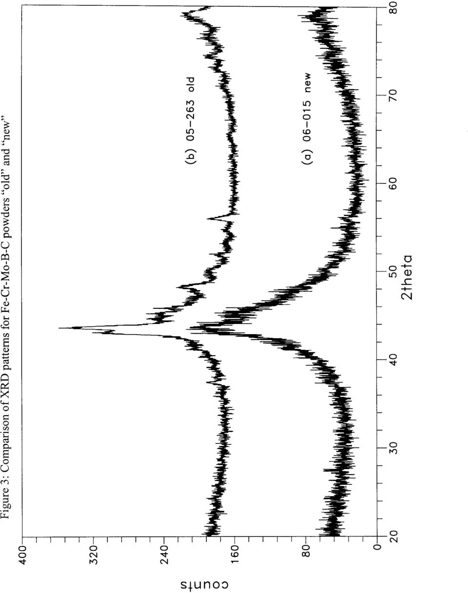
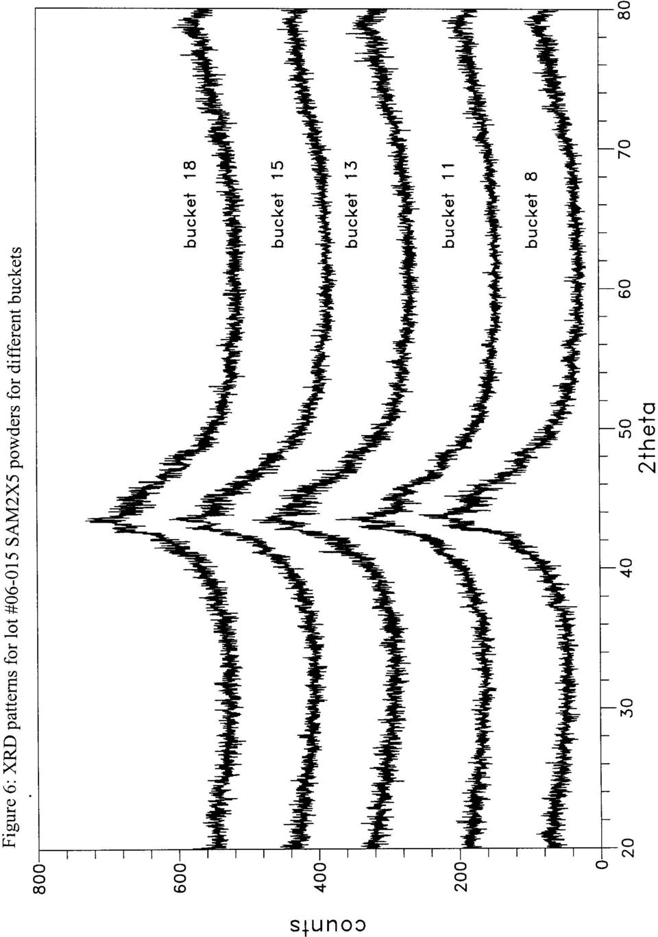
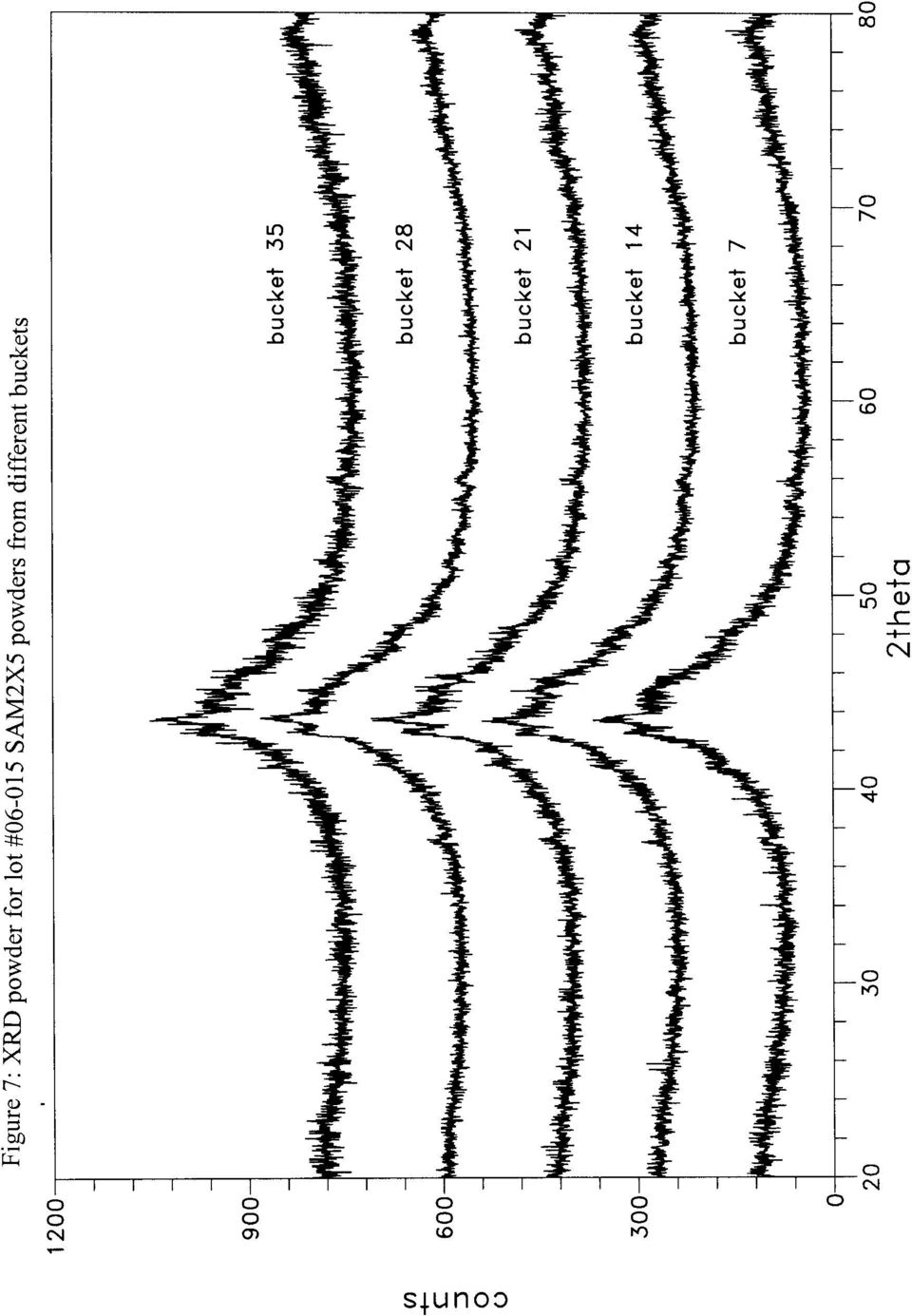
7 ribbons are essentially melt-spun from the powders and the coatings are thermal sprayed onto a surface. VI (a) Powders Figure 1 shows the resulting diffraction pattern for the SAM2X5 powder samples manufactured by The NanoSteel Company in 2004 and SAM2X5 is the Mo series with 5% Mo in SAM40 and SAM40 consists of 50Fe-18Cr-15B-2Si-2Mn-2W. The lot # and the powder fraction size are also given in the Table. Lot # 04 was produced in FY04, and lot #05 was produced in FY05. Particle sizes are listed along with the lot # s. Lot # means powder from lot # with particle size ranging from 15 to 53 um. Both amorphous and crystalline phases can be observed. The results suggest that lot # 05 is more crystalline than lot # 04. Figure 2 compares the XRD patterns with some possible ICDD (International Center for Diffraction Data) data base compounds. It is most likely that the crystalline components are alloys of boron chromium, chromium carbide, possibly iron chromium and iron. An amorphous structure is observed for the lot # sample and partially amorphous for lot # and # Figure 3 shows the resulting diffraction of the SAM2X5 powder from lot # prepared in FY06, also labeled as new and lot # labeled as old prepared in FY05 by Nanosteel. Clearly, they are not similar. Lot # is essentially amorphous. The crystalline lines appear to be those of alloys of iron carbide, boron iron and possible iron chromium as indicated in Figure 4. Figures 5, 6 and 7 show the resulting diffraction patterns for a set of powder samples of SAM2X5 from lot # taken from different buckets labeled from 1 to 35. The results suggest, except for bucket #1, the powders are essentially similar with the major component having the amorphous structure and some amount of crystallinity. The small amount of crystallinity can probably be attributed to alloys of boron iron as indicated in Figure 8. Figure 9 shows the diffraction patterns from the powders of lot # The results are very similar for all the samples from different bucket. Again, the major component is amorphous with minor crystalline phase which is probably alloy of boron iron as indicated in the ICDD listing of Figure 8. VI (b) Ribbons Melt-spun ribbons are also submitted for investigation. The samples were also prepared by NanoSteel Company. Figure 10 shows the resulting diffraction patterns of the melt spun ribbons for C22 and 316L steel which clearly indicate both materials are crystalline and melt spin process cannot capture the amorphous meta-stable state of these alloys. Figure 11 compares the resulting diffraction pattern of ribbons for samples (a) SAM2X1, (b) SAM2X3, (c) SAM2X5 and (d) SAM2X7 for the Mo series where (a) is 1%, (b) 3%, (c) 5% and (d) 7% Mo concentration. Clearly, the results indicate that these ribbon samples are amorphous as evidence by a single broad x-ray peak.

8 Figure 12 shows the resulting diffraction pattern for (e) SAM6, (f) SAM7, (g) SAM8 and (h) SAM40 ribbons. Only one major broad peak is observed in all the samples indicating that the materials are amorphous. Figure 13 compares the diffraction patterns for the SAM1Xn series, where n is equals to 1, 3, 5 and 7 % nickel. The results indicate that the samples are amorphous and show no significant amount of crystallinity. Figure 14 compares the resulting diffraction patterns for the SAM3Xn series, where n is equals to 1, 3, 5 and 7% yttrium. Again, all the ribbons are essentially amorphous. VI (c) Coatings Figures show all the coatings from SAM2X5 materials except one from SAM1651 as identified in 15 (b). Figure 15 shows the result for a set of coating samples where (a) E316L471 is a spalled coating of SAM1651 (b) E316L463 is the coating on a 316L substrate (c) E316L504 and (d) W316L329 are coatings on 316L substrate. In most cases, some level of crystallinity is observed on top of the major amorphous component. The spalled sample (a) and sample (c) SAM2X5 EL316L504 show the most amount of amorphous component. There are some crystalline lines and they can be indexed to iron oxide Fe 3 O 4 as indicated in Figure 16. Samples (b) 04-E316L471 and (d) 04-E316L504 are essentially similar. The major amorphous component can be observed with a small amount of crystallinity which is probably due to iron boron alloy and iron oxide as shown in Figure 17. For sample (f) M6SI lot #05-079, an additional crystalline component can be observed as indicated by the additional x-ray lines. The lines can be indexed to crystalline iron. Figure 18 shows the diffraction patterns of alloy coatings, PTI-A, PTI-B and PTI-C on 316L substrate. Essentially, the material is amorphous, however some amount of crystalline component can be observed. The crystalline components are due to iron oxide and boron iron alloy. The resulting diffraction patterns for coatings from SAM2X5 lot # labeled as PTI-358-C1, C2 and C3 are similar to that of PTI-C as shown in Figure 18. They are essentially amorphous with a small amount of crystallinity, probably due to iron oxide and iron boron. VII. CONCLUSIONS X-ray diffraction technique has been developed to examine the structure of SAM samples in the form of powder, ribbons and coatings. Since the samples contain a significant amount of iron, diffracted beam discrimination is needed. The results are consistent with those examined by other laboratory. From this work, it can be concluded that the production of amorphous iron base alloys material critically depends on the multiple elemental compositions. C22 and 316L alloys did not form the amorphous phase. The multiple elements essentially ensure the increase of the free energy, thus preventing like elements from forming crystalline ordered states. Differences in crystallinity can be observed from the same powder samples of different lot s as evidence from the examination of the same materials. Both lot # and 05-

9 samples and lot # are highly crystalline which are identified to be alloys of boron chromium, chromium carbide, iron chromium, iron carbide and boron iron. Lot # is essentially amorphous. No processing information is available hence presumably these differences are due to thermal history and/or crystallite sizes. A new lot # powder sample was submitted and compared to the lot # and the result indicates that this new sample is amorphous. A set of powder samples of SAM2X5 of lot # from bucket #1 to #35 were examined. Except for sample from bucket #1 in lot # which has significantly more crystallinity, the major component is essentially amorphous for the rest of the samples with a very small amount of crystalline boron iron alloy. Lot # is also amorphous with a small amount of crystalline boron iron alloy. Amorphous melt-spun ribbon samples cannot be prepared for C22 and 316L materials, they both show crystallinity. All the ribbons samples exhibit an amorphous structure. There are some differences in the structure of the thermal spray coatings depending on the starting powder samples. In most cases, the major amorphous component can be observed with a small amount of crystalline component. However, starting from an amorphous powder, an amorphous coating can be achieved with a small amount of crystallinity due to oxidation of iron. VIII. REFERENCES [1] Latanison, R.M., Workshop on Amorphous Metals and Semiconductors, EPRI, May (1985) [2] J. C. Farmer, J. J. Haslam, F. Wong, X. Ji, S. D. Day, D. J. Branagan, M. C. Marshall, B. E. Meacham, E. J. Buffa, C. A. Blue, J. D. K. Rivard, M. B. Beardsley, D. T. Weaver, L. F. Aprigliano, L. Kohler, R. Bayles, E. J. Lemieux, T. M. Wolejsza, F. J. Martin, N. Yang, G. Lucadamo, J.H. Perepezko, K. Hilda!, L. Kaufman, A. H. Heuer, F. Ernst, G. M. Michal, H. Kahn, E. J. Lavernia, High- Performance Corrosion-Resistant Materials: Iron-Based Amorphous-Metal Thermal- Spray Coatings, Am. Soc. of Mechanical Engineers, Pressure Vessels & Piping (PVP) Conf. July 2005 [3] Saw, C.K., X-ray Scattering Techniques for Characterization Tools in the Life Sciences, Nanotechnologies for the Life Science, Edited by Challa Kumar, Wiley- VCH Verlag GmbH & Co., KGaA, Weinheim, 2006 [4] Saw C.K. and Schwarz, R.B., Chemical short-range order in dense random-packed models, J. of the Less-Common Metals, 1988, 140,

10 Table I: Samples description for the powders X-ray # ID Description Form Label X3017 Bucket #1 SAM 2x5 lot# P Amorphous +crystalline X3018 Bucket #30 SAM 2x5 lot # P Amorphous +crystalline X3019 Bucket #40 SAM 2x5 lot # P Amorphous +crystalline X3020 Bucket #45 SAM 2x5 lot # P Amorphous +crystalline X3021 Bucket #60 SAM 2x5 lot # P Amorphous X3069 Nanosteel SAM2X5 lot # P Amorphous X3080 Nanosteel SAM2X5 lot # P Amorphous + crystalline X3132 Nanosteel SAM2X5 lot # Bucket #1 P Amorphous +crystalline X3133 Nanosteel SAM2X5 lo t# Bucket #2 P Amorphous X3134 Nanosteel SAM2X5 lot # Bucket #3 P Amorphous X3135 Nanosteel SAM2X5 lot # Bucket #4 P Amorphous X3144 Nanosteel SAM2X5 lot # Bucket #7 P Amorphous X3112 Nanosteel SAM 2X5 lot # bucket PT#8 P Amorphous X3113 Nanosteel SAM 2X5 lot # bucket PT#11 P Amorphous X3114 Nanosteel SAM 2X5 lot # bucket PT# 13 P Amorphous X3115 Nanosteel SAM 2X5 lot # bucket PT#15 P Amorphous X3116 Nanosteel SAM 2X5 lot # bucket PT#18 P Amorphous X3145 Nanosteel SAM2X5 lot # Bucket #14 P Amorphous X3146 Nanosteel SAM2X5 lot # Bucket #21 P Amorphous X3147 Nanosteel SAM2X5 lot # Bucket #28 P Amorphous X3148 Nanosteel SAM2X5 lot # Bucket #35 P Amorphous X3139 Nanosteel SAM2X5 lot # bucket #7 P Amorphous +crystalline X3140 Nanosteel SAM2X5 lot # bucket #9 P Amorphous X3141 Nanosteel SAM2X5 lot # bucket #11 P Amorphous X3142 Nanosteel SAM2X5 lot # bucket #13 P Amorphous X3143 Nanosteel SAM2X5 lot # bucket #15 P Amorphous

11 Table II: Sample description for the ribbons X3233 SAM1X1 SAM1X1 series 1% Ni R Amorphous X3234 SAM1X3 SAM1X3 series 3% Ni R Amorphous X3235 SAM1X5 SAM1X5 series 5% Ni R Amorphous X3236 SAM1X7 SAM1X7 series 7% Ni R Amorphous X3237 SAM3X1 SAM3X1 series 1%Y R Amorphous X3238 SAM3X3 SAM3X3 series 3%Y R Amorphous X3239 SAM3X5 SAM3X5 series 5%Y R Amorphous X3240 SAM3X7 SAM3X7 series 7%Y R Amorphous X3214 SAM2X1 SAM2X1 series 1% Mo R Amorphous + crystalline X3214 SAM2X3 SAM2X3 series 3% Mo R Amorphous + crystalline X3074 SAM2X5 SAM2X5 series 5% Mo R Amorphous X3075 SAM2X7 SAM2X7 series 7% Mo R Amorphous X3070 C22 57Ni-22Cr-13Mo-2Fe-3W-Co R Crystalline est. a=3.60a X L Fe-20Cr-10Ni-3Mo-Mn R Crystalline est. a=358a X3076 SAM6 43Fe-16Cr-16Mo-10C-10P-5B R Amorphous X3101 SAM7 Fe-Cr-Mo-B-C (1651) R Amorphous X3102 SAM8 Fe-Cr-Mo-B-C (3%W) R Amorphous X3079 SAM40 52Fe-19Cr-16B-4C-2Si-2Mo-2Mn-2W R Amorphous

12 Table III: Sample description for the coatings X-ray # ID Description Forms X3103 PWD SAM2X5 powder P 50Fe18Cr15B4C5Mo2Si2Mn2W (lot # 05) Amorphous +crystalline X3104 E316L471 Spalled coating SAM1651disk (lot #04) C Amorphous +crystalline X3105 E316L463 SAM2X5 coating disk (lot # 04) C Amorphous +crystalline X3106 E316L504 SAM2X5 lot # µm C Amorphous +crystalline X3107 W316L329 SAM2X5 lot # µm C Amorphous +crystalline X3108 M6S1 SAM2X5 lot # µm C Amorphous +crystalline X3136 PTI-A SAM2X5 on 316L substrate C Amorphous +crystalline X3137 PTI-B SAM2X5 on 316L substrate C Amorphous +crystalline X3138 PTI-C SAM2X5 on 316L substrate C Amorphous +crystalline X3101b SAM7 Fe-Cr-Mo-B-C not shinning side R Amorphous X3159 PTI-358-C1 SAM2X5 lot # coating C Amorphous +crystalline X3160 PTI-358-C2 SAM2X5 lot # coating C Amorphous +crystalline X3161 PTI-358-C3 SAM2X5 lot # coating C Amorphous + crystalline X L-W10 316L plate with SAM2X5 lot # C Amorphous X3242 C22-W22 C22 plate coating SAM2X5 lot # C Amorphous C22: Ni-Cr-Mo-Fe-W-Co 316L: Fe-Cr-Ni-Mo-Mn SAM2X1: Fe-Cr-B-C-Mo-Si-Mn-W SAM2X3: Fe-Cr-B-C-Mo-Si-Mn-W SAM2X5: Fe-Cr-B-C-Mo-Si-Mn-W SAM2X7: Fe-Cr-B-C-Mo-Si-Mn-W SAM2X1-50Fe-18Cr-15B-4C-1Mo-2Si-2Mn-2W SAM2X3-50Fe-18Cr-15B-4C-3Mo-2Si-2Mn-2W SAM2X5-50Fe-18Cr-15B-4C-5Mo-2Si-2Mn-2W SAM2X7-50Fe-18Cr-15B-4C-7Mo-2Si-2Mn-2W SAM6-43Fe-16Cr-16Mo-10C-10P-5B SAM7-48Fe-15Cr-15C-14Mo-6B-2Y SAM8-47Fe-15Cr-15C-13Mo-6B-3W-2Y SAM40-52Fe-19Cr-16B-4C-2Si-2Mo-2Mn-2W

13

14

15
16

17

18
19
20

21
22
23
24
25
26
27
28
29
30
X-Ray Diffraction HOW IT WORKS WHAT IT CAN AND WHAT IT CANNOT TELL US. Hanno zur Loye
 X-Ray Diffraction HOW IT WORKS WHAT IT CAN AND WHAT IT CANNOT TELL US Hanno zur Loye X-rays are electromagnetic radiation of wavelength about 1 Å (10-10 m), which is about the same size as an atom. The
Defect studies of optical materials using near-field scanning optical microscopy and spectroscopy
 UCRL-ID-142178 Defect studies of optical materials using near-field scanning optical microscopy and spectroscopy M. Yan, J. McWhirter, T. Huser, W. Siekhaus January, 2001 U.S. Department of Energy Laboratory
X-ray Diffraction and EBSD
 X-ray Diffraction and EBSD Jonathan Cowen Swagelok Center for the Surface Analysis of Materials Case School of Engineering Case Western Reserve University October 27, 2014 Outline X-ray Diffraction (XRD)
Chapter 7: Basics of X-ray Diffraction
 Providing Solutions To Your Diffraction Needs. Chapter 7: Basics of X-ray Diffraction Scintag has prepared this section for use by customers and authorized personnel. The information contained herein is
X-ray thin-film measurement techniques
 Technical articles X-ray thin-film measurement techniques II. Out-of-plane diffraction measurements Toru Mitsunaga* 1. Introduction A thin-film sample is two-dimensionally formed on the surface of a substrate,
Crystal Structure Determination I
 Crystal Structure Determination I Dr. Falak Sher Pakistan Institute of Engineering and Applied Sciences National Workshop on Crystal Structure Determination using Powder XRD, organized by the Khwarzimic
X-ray diffraction techniques for thin films
 X-ray diffraction techniques for thin films Rigaku Corporation Application Laboratory Takayuki Konya 1 Today s contents (PM) Introduction X-ray diffraction method Out-of-Plane In-Plane Pole figure Reciprocal
Introduction to X-Ray Powder Diffraction Data Analysis
 Introduction to X-Ray Powder Diffraction Data Analysis Center for Materials Science and Engineering at MIT http://prism.mit.edu/xray An X-ray diffraction pattern is a plot of the intensity of X-rays scattered
X-ray Diffraction (XRD)
") X-ray Diffraction (XRD) 1.0 What is X-ray Diffraction 2.0 Basics of Crystallography 3.0 Production of X-rays 4.0 Applications of XRD 5.0 Instrumental Sources of Error 6.0 Conclusions Bragg s Law n l =2dsinq
X-ray Diffraction (XRD) 1.0 What is X-ray Diffraction 2.0 Basics of Crystallography 3.0 Production of X-rays 4.0 Applications of XRD 5.0 Instrumental Sources of Error 6.0 Conclusions Bragg s Law n l =2dsinq
Powder diffraction and synchrotron radiation
 Powder diffraction and synchrotron radiation Gilberto Artioli Dip. Geoscienze UNIPD CIRCe Center for Cement Materials single xl diffraction powder diffraction Ideal powder Powder averaging Textured sample
Crystal Structure of High Temperature Superconductors. Marie Nelson East Orange Campus High School NJIT Professor: Trevor Tyson
 Crystal Structure of High Temperature Superconductors Marie Nelson East Orange Campus High School NJIT Professor: Trevor Tyson Introduction History of Superconductors Superconductors are material which
INFRARED MONITORING OF 110 GHz GYROTRON WINDOWS AT DIII D
 GA A23981 INFRARED MONITORING OF 110 GHz GYROTRON WINDOWS AT DIII D by Y. GORELOV, J. LOHR, R.W. CALLIS, and D. PONCE MAY 2002 DISCLAIMER This report was prepared as an account of work sponsored by an
Introduction to Powder X-Ray Diffraction History Basic Principles
 Introduction to Powder X-Ray Diffraction History Basic Principles Folie.1 History: Wilhelm Conrad Röntgen Wilhelm Conrad Röntgen discovered 1895 the X-rays. 1901 he was honoured by the Noble prize for
Glancing XRD and XRF for the Study of Texture Development in SmCo Based Films Sputtered Onto Silicon Substrates
 161 162 Glancing XRD and XRF for the Study of Texture Development in SmCo Based Films Sputtered Onto Silicon Substrates F. J. Cadieu*, I. Vander, Y. Rong, and R. W. Zuneska Physics Department Queens College
Applications of New, High Intensity X-Ray Optics - Normal and thin film diffraction using a parabolic, multilayer mirror
 Applications of New, High Intensity X-Ray Optics - Normal and thin film diffraction using a parabolic, multilayer mirror Stephen B. Robie scintag, Inc. 10040 Bubb Road Cupertino, CA 95014 Abstract Corundum
Confocal μ-xrf for 3D analysis of elements distribution in hot environmental particles
 LLNL-TR-400056 LAWRENCE LIVERMORE NATIONAL LABORATORY Confocal μ-xrf for 3D analysis of elements distribution in hot environmental particles M. Bielewski M. Eriksson J. Himbert R. Simon M. Betti T.F. Hamilton
Radioactive Waste Storage Facility and Tank System Design Criteria Standards
 UCRL-AR-133355 Rev 1 Radioactive Waste Storage Facility and Tank System Design Criteria Standards John Wood Rich Michalik Karen Doiron May 1999 DISCLAIMER This document was prepared as an account of work
Experiment: Crystal Structure Analysis in Engineering Materials
 Experiment: Crystal Structure Analysis in Engineering Materials Objective The purpose of this experiment is to introduce students to the use of X-ray diffraction techniques for investigating various types
Time Domain Reflectometry for Evaluating Detonator Cable Assemblies in the NEP
 Time Domain Reflectometry for Evaluating Detonator Cable Assemblies in the NEP R. M. Morey June 14, 2005 JOWOG 9 Reading, Berkshire, United Kingdom June 22, 2005 through June 24, 2005 Disclaimer This document
X-RAY DIFFRACTION IMAGING AS A TOOL OF MESOSTRUCTURE ANALYSIS
 Copyright(c)JCPDS-International Centre for Diffraction Data 2001,Advances in X-ray Analysis,Vol.44 241 X-RAY DIFFRACTION IMAGING AS A TOOL OF MESOSTRUCTURE ANALYSIS ABSTRACT J. Fiala, S. Němeček Škoda
Solidification, Crystallization & Glass Transition
 Solidification, Crystallization & Glass Transition Cooling the Melt solidification Crystallization versus Formation of Glass Parameters related to the formaton of glass Effect of cooling rate Glass transition
Microscopy and Nanoindentation. Combining Orientation Imaging. to investigate localized. deformation behaviour. Felix Reinauer
 Combining Orientation Imaging Microscopy and Nanoindentation to investigate localized deformation behaviour Felix Reinauer René de Kloe Matt Nowell Introduction Anisotropy in crystalline materials Presentation
North American Stainless
 North American Stainless Flat Products Stainless Steel Grade Sheet 310S (S31008)/ EN 1.4845 Introduction: SS310 is a highly alloyed austenitic stainless steel designed for elevated-temperature service.
X-ray Powder Diffraction Pattern Indexing for Pharmaceutical Applications
 The published version of this manuscript may be found at the following webpage: http://www.pharmtech.com/pharmtech/peer-reviewed+research/x-ray-powder-diffraction-pattern-indexing-for- Phar/ArticleStandard/Article/detail/800851
North American Stainless
 Introduction: North American Stainless Flat Products Stainless Steel Grade Sheet 309S (S30908)/ EN1.4833 SS309 is a highly alloyed austenitic stainless steel used for its excellent oxidation resistance,
DISCLAIMER. This document was prepared as an account of work sponsored by an agency of the United States
 DISCLAIMER This document was prepared as an account of work sponsored by an agency of the United States Government. Neither the United States Government nor the University of California nor any of their
Experiment titles: Anion exchange studies in photoluminescent clayinspired. Local contact(s): Dr. Wouter van Beek (E-mail: wouter@esrf.
: Dr. Wouter van Beek (E-mail: wouter@esrf.") Experiment titles: Anion exchange studies in photoluminescent clayinspired Frameworks Experiment number: CH-3994 Beamline: BM01b Shifts: 6 Date of experiment: from: 30 Sept. 2013 to: 03 Oct. 2013 Local
Experiment titles: Anion exchange studies in photoluminescent clayinspired Frameworks Experiment number: CH-3994 Beamline: BM01b Shifts: 6 Date of experiment: from: 30 Sept. 2013 to: 03 Oct. 2013 Local
Atomic Force Microscope and Magnetic Force Microscope Background Information
 Atomic Force Microscope and Magnetic Force Microscope Background Information Lego Building Instructions There are several places to find the building instructions for building the Lego models of atomic
Wafer Manufacturing. Reading Assignments: Plummer, Chap 3.1~3.4
 Wafer Manufacturing Reading Assignments: Plummer, Chap 3.1~3.4 1 Periodic Table Roman letters give valence of the Elements 2 Why Silicon? First transistor, Shockley, Bardeen, Brattain1947 Made by Germanium
Active Vibration Isolation of an Unbalanced Machine Spindle
 UCRL-CONF-206108 Active Vibration Isolation of an Unbalanced Machine Spindle D. J. Hopkins, P. Geraghty August 18, 2004 American Society of Precision Engineering Annual Conference Orlando, FL, United States
Preface Light Microscopy X-ray Diffraction Methods
 Preface xi 1 Light Microscopy 1 1.1 Optical Principles 1 1.1.1 Image Formation 1 1.1.2 Resolution 3 1.1.3 Depth of Field 5 1.1.4 Aberrations 6 1.2 Instrumentation 8 1.2.1 Illumination System 9 1.2.2 Objective
Structure Factors 59-553 78
 78 Structure Factors Until now, we have only typically considered reflections arising from planes in a hypothetical lattice containing one atom in the asymmetric unit. In practice we will generally deal
Final Report. Period Start Date: October 1, 2000 Period End Date: September 30, 2002
 Development of Advanced Drill Components for BHA Using Microwave Technology Incorporating Carbide, Diamond Composites and Functionally Graded Materials Final Report Period Start Date: October 1, 2000 Period
Tableting Punch Performance Can Be Improved With Precision Coatings
 Tableting Punch Performance Can Be Improved With Precision Coatings by Arnold H. Deutchman, Ph. D. Director of Research and Development (614) 873-4529 X 114 adeutchman@beamalloy.net Mr. Dale C. Natoli
POWDER X-RAY DIFFRACTION: STRUCTURAL DETERMINATION OF ALKALI HALIDE SALTS
 EXPERIMENT 4 POWDER X-RAY DIFFRACTION: STRUCTURAL DETERMINATION OF ALKALI HALIDE SALTS I. Introduction The determination of the chemical structure of molecules is indispensable to chemists in their effort
CVD SILICON CARBIDE. CVD SILICON CARBIDE s attributes include:
 CVD SILICON CARBIDE CVD SILICON CARBIDE is the ideal performance material for design engineers. It outperforms conventional forms of silicon carbide, as well as other ceramics, quartz, and metals in chemical
Sputtered AlN Thin Films on Si and Electrodes for MEMS Resonators: Relationship Between Surface Quality Microstructure and Film Properties
 Sputtered AlN Thin Films on and Electrodes for MEMS Resonators: Relationship Between Surface Quality Microstructure and Film Properties S. Mishin, D. R. Marx and B. Sylvia, Advanced Modular Sputtering,
Chapter Outline Dislocations and Strengthening Mechanisms
 Chapter Outline Dislocations and Strengthening Mechanisms What is happening in material during plastic deformation? Dislocations and Plastic Deformation Motion of dislocations in response to stress Slip
2. Deposition process
 Properties of optical thin films produced by reactive low voltage ion plating (RLVIP) Antje Hallbauer Thin Film Technology Institute of Ion Physics & Applied Physics University of Innsbruck Investigations
PHOTOELECTRIC EFFECT AND DUAL NATURE OF MATTER AND RADIATIONS
 PHOTOELECTRIC EFFECT AND DUAL NATURE OF MATTER AND RADIATIONS 1. Photons 2. Photoelectric Effect 3. Experimental Set-up to study Photoelectric Effect 4. Effect of Intensity, Frequency, Potential on P.E.
Phase Characterization of TiO 2 Powder by XRD and TEM
 Kasetsart J. (Nat. Sci.) 42 : 357-361 (28) Phase Characterization of TiO 2 Powder by XRD and TEM Kheamrutai Thamaphat 1 *, Pichet Limsuwan 1 and Boonlaer Ngotawornchai 2 ABSTRACT In this study, the commercial
Defects Introduction. Bonding + Structure + Defects. Properties
 Defects Introduction Bonding + Structure + Defects Properties The processing determines the defects Composition Bonding type Structure of Crystalline Processing factors Defects Microstructure Types of
Materials Sciences. Dr.-Ing. Norbert Hort norbert.hort@gkss.de. International Masters Programme in Biomedical Engineering
 Materials Sciences International Masters Programme in Biomedical Engineering Magnesium Innovations Center (MagIC) GKSS Forschungszentrum Geesthacht GmbH Dr.-Ing. Norbert Hort norbert.hort@gkss.de Contents
WinMagic Encryption Software Installation and Configuration
 WinMagic Encryption Software Installation and Configuration Don Mendonsa, Faranak Nekoogar, Harry Martz Lawrence Livermore National Laboratory Livermore, CA 94551 Work performed on the Science & Technology
North American Stainless
 North American Stainless Long Products Stainless Steel Grade Sheet 2205 UNS S2205 EN 1.4462 2304 UNS S2304 EN 1.4362 INTRODUCTION Types 2205 and 2304 are duplex stainless steel grades with a microstructure,
Preparation of ZnS and SnS Nanopowders by Modified SILAR Technique
 Journal of Physical Sciences, Vol. 13, 009, 9-34 ISSN: 097-8791 : www.vidyasagar.ac.in/journal Preparation of ZnS and SnS Nanopowders by Modified SILAR Technique Department of Physics The University of
Molecular Dynamics Study of Void Growth and Dislocations in dynamic Fracture of FCC and BCC Metals
 Preprint UCRL-JC-151375 Molecular Dynamics Study of Void Growth and Dislocations in dynamic Fracture of FCC and BCC Metals E. T. Seppala, J. Belak, R. E. Rudd This article was submitted to: Plasticity
Chapter 3. 1. 3 types of materials- amorphous, crystalline, and polycrystalline. 5. Same as #3 for the ceramic and diamond crystal structures.
 Chapter Highlights: Notes: 1. types of materials- amorphous, crystalline, and polycrystalline.. Understand the meaning of crystallinity, which refers to a regular lattice based on a repeating unit cell..
This is an author-deposited version published in: http://sam.ensam.eu Handle ID:.http://hdl.handle.net/10985/10324
 Science Arts & Métiers (SAM) is an open access repository that collects the work of Arts et Métiers ParisTech researchers and makes it freely available over the web where possible. This is an author-deposited
Introduction to microstructure
 Introduction to microstructure 1.1 What is microstructure? When describing the structure of a material, we make a clear distinction between its crystal structure and its microstructure. The term crystal
LASER CUTTING OF STAINLESS STEEL
 LASER CUTTING OF STAINLESS STEEL Laser inert gas cutting is the most applicable process type used for cutting of stainless steel. Laser oxygen cutting is also applied in cases where the cut face oxidation
A VACUUM WINDOW FOR A 1 MW CW 110 GHz GYROTRON
 GA-A21741 A VACUUM WINDOW FOR A 1 MW CW 110 GHz GYROTRON by C.P. MOELLER, J.L. DOANE, and M. DiMARTINO This is a preprint of a paper to be presented at the 19th International Conference on Infrared and
The study of structural and optical properties of TiO 2 :Tb thin films
 Optica Applicata, Vol. XXXVII, No. 4, 2007 The study of structural and optical properties of TiO 2 :Tb thin films AGNIESZKA BORKOWSKA, JAROSLAW DOMARADZKI, DANUTA KACZMAREK, DAMIAN WOJCIESZAK Faculty of
NON DESTRUCTIVE TESTING & ASNT WELD INSPECTION & AWS
 NON DESTRUCTIVE TESTING & ASNT WELD INSPECTION & AWS What is ASNT? What is ASNT? The American Society for Nondestructive Testing, Inc. What is ASNT? ASNT is the world's largest technical society for nondestructive
Technology White Papers nr. 13 Paul Holister Cristina Román Vas Tim Harper
 QUANTUM DOTS Technology White Papers nr. 13 Paul Holister Cristina Román Vas Tim Harper QUANTUM DOTS Technology White Papers nr. 13 Release Date: Published by Científica Científica, Ltd. www.cientifica.com
Plate waves in phononic crystals slabs
 Acoustics 8 Paris Plate waves in phononic crystals slabs J.-J. Chen and B. Bonello CNRS and Paris VI University, INSP - 14 rue de Lourmel, 7515 Paris, France chen99nju@gmail.com 41 Acoustics 8 Paris We
Material data sheet. EOS CobaltChrome MP1. Description
 EOS CobaltChrome MP1 EOS CobaltChrome MP1 is a cobalt-chrome-molybdenum-based superalloy powder which has been optimized especially for processing on EOSINT M systems. This document provides information
ME 612 Metal Forming and Theory of Plasticity. 1. Introduction
 Metal Forming and Theory of Plasticity Yrd.Doç. e mail: azsenalp@gyte.edu.tr Makine Mühendisliği Bölümü Gebze Yüksek Teknoloji Enstitüsü In general, it is possible to evaluate metal forming operations
Formation of solids from solutions and melts
 Formation of solids from solutions and melts Solids from a liquid phase. 1. The liquid has the same composition as the solid. Formed from the melt without any chemical transformation. Crystallization and
IUCLID 5 COMPOSITION AND ANALYSIS GUIDANCE DOCUMENT: IRON ORES, AGGLOMERATES [EINECS NUMBER 265 996 3, CAS NUMBER 65996 65 8] IRON ORE PELLETS
![IUCLID 5 COMPOSITION AND ANALYSIS GUIDANCE DOCUMENT: IRON ORES, AGGLOMERATES [EINECS NUMBER 265 996 3, CAS NUMBER 65996 65 8] IRON ORE PELLETS](/thumbs/40/20960122.jpg "IUCLID 5 COMPOSITION AND ANALYSIS GUIDANCE DOCUMENT: IRON ORES, AGGLOMERATES [EINECS NUMBER 265 996 3, CAS NUMBER 65996 65 8] IRON ORE PELLETS") IUCLID 5 COMPOSITION AND ANALYSIS GUIDANCE DOCUMENT: IRON ORES, AGGLOMERATES [EINECS NUMBER 265 996 3, CAS NUMBER 65996 65 8] IRON ORE PELLETS INTRODUCTION Each REACH registrant is required to file its
IUCLID 5 COMPOSITION AND ANALYSIS GUIDANCE DOCUMENT: IRON ORES, AGGLOMERATES [EINECS NUMBER 265 996 3, CAS NUMBER 65996 65 8] IRON ORE PELLETS INTRODUCTION Each REACH registrant is required to file its
Sample Exercise 12.1 Calculating Packing Efficiency
 Sample Exercise 12.1 Calculating Packing Efficiency It is not possible to pack spheres together without leaving some void spaces between the spheres. Packing efficiency is the fraction of space in a crystal
New Portable X-Ray Diffraction/X-Ray Fluorescence Instrument (XRD/XRF)
") 1 New Portable X-Ray Diffraction/X-Ray Fluorescence Instrument (XRD/XRF) Introduction The primary goal of most analyses of art objects is to identify the material composition of the object. This may lead
1 New Portable X-Ray Diffraction/X-Ray Fluorescence Instrument (XRD/XRF) Introduction The primary goal of most analyses of art objects is to identify the material composition of the object. This may lead
Laue lens for Nuclear Medicine
 Laue lens for Nuclear Medicine PhD in Physics Gianfranco Paternò Ferrara, 6-11-013 Supervisor: prof. Vincenzo Guidi Sensors and Semiconductors Lab, Department of Physics and Earth Science, University of
This document was prepared in conjunction with work accomplished under Contract No. DE-AC09-96SR18500 with the U. S. Department of Energy.
 This document was prepared in conjunction with work accomplished under Contract No. DE-AC09-96SR18500 with the U. S. Department of Energy. DISCLAIMER This report was prepared as an account of work sponsored
LLNL-TR-419602. SAVANT Status Report. Arden Dougan. November 6, 2009
 LLNL-TR-419602 SAVANT Status Report Arden Dougan November 6, 2009 Disclaimer This document was prepared as an account of work sponsored by an agency of the United States government. Neither the United
Brush Plating of Nickel-Tungsten Alloy for Engineering Application
 Brush Plating of Nickel-Tungsten Alloy for Engineering Application Zhimin Zhong & Sid Clouser ASETS Defense 12 1 Engineering (functional) applications Hardness, wear resistance, & corrosion protection
SALT SPRAY AND IMMERSION CORROSION TESTING OF PM STAINLESS STEEL MATERIALS. W. Brian James Hoeganaes Corporation. Cinnaminson, NJ 08077
 SALT SPRAY AND IMMERSION CORROSION TESTING OF PM STAINLESS STEEL MATERIALS W. Brian James Hoeganaes Corporation Cinnaminson, NJ 08077 Leander F. Pease III Powder-Tech Associates Inc. Andover, MA 01845
Bruker AXS. D2 PHASER Diffraction Solutions XRD. think forward
 Bruker AXS D2 PHASER Diffraction Solutions think forward XRD Compact all-in-one desktop design Innovative high-end goniometer design Integrated PC / monitor DIFFRAC.SUITE software Leading detector technology
A Compact Linac for Proton Therapy Based on a Dielectric Wall Accelerator
 UCRL-CONF-236077 A Compact Linac for Proton Therapy Based on a Dielectric Wall Accelerator G. J. Caporaso, T. R. Mackie, S. Sampayan, Y. -J. Chen, D. Blackfield, J. Harris, S. Hawkins, C. Holmes, S. Nelson,
Cleaning of Free Machining Brass
 UCRL-TR-217975 Cleaning of Free Machining Brass T. Shen January 5, 2006 Disclaimer This document was prepared as an account of work sponsored by an agency of the United States Government. Neither the United
The Cost of Superconducting Magnets as a Function of Stored Energy and Design Magnetic Induction times the Field Volume
 MT-20 Paper 4V-02, to be published in IEEE Transactions on Applied Superconductivity 8, No. 2, LBNL-63482 The Cost of Superconducting Magnets as a Function of Stored Energy Design Magnetic Induction times
Laboratory #3 Guide: Optical and Electrical Properties of Transparent Conductors -- September 23, 2014
 Laboratory #3 Guide: Optical and Electrical Properties of Transparent Conductors -- September 23, 2014 Introduction Following our previous lab exercises, you now have the skills and understanding to control
bulk 5. Surface Analysis Why surface Analysis? Introduction Methods: XPS, AES, RBS
 5. Surface Analysis Introduction Methods: XPS, AES, RBS Autumn 2011 Experimental Methods in Physics Marco Cantoni Why surface Analysis? Bulk: structural function Electrical/thermal conduction Volume increases
Optics and Spectroscopy at Surfaces and Interfaces
 Vladimir G. Bordo and Horst-Gunter Rubahn Optics and Spectroscopy at Surfaces and Interfaces WILEY- VCH WILEY-VCH Verlag GmbH & Co. KGaA Contents Preface IX 1 Introduction 1 2 Surfaces and Interfaces 5
Measurement of BET Surface Area on Silica Nanosprings
 PNNL-17648 Prepared for the U.S. Department of Energy under Contract DE-AC05-76RL01830 Measurement of BET Surface Area on Silica Nanosprings AJ Karkamkar September 2008 DISCLAIMER This report was prepared
Laser Safety Audit and Inventory System Database
 SAND REPORT SAND2003-1144 Unlimited Release Printed May 2003 Laser Safety Audit and Inventory System Database Arnold L. Augustoni Prepared by Sandia National Laboratories Albuquerque, New Mexico 87185
ATI 2205 ATI 2205. Technical Data Sheet. Duplex Stainless Steel GENERAL PROPERTIES. (UNS S31803 and S32205)
") ATI 2205 Duplex Stainless Steel (UNS S31803 and S32205) GENERAL PROPERTIES ATI 2205 alloy (UNS S31803 and/or S32205) is a nitrogen-enhanced duplex stainless steel alloy. The nitrogen serves to significantly
ATI 2205 Duplex Stainless Steel (UNS S31803 and S32205) GENERAL PROPERTIES ATI 2205 alloy (UNS S31803 and/or S32205) is a nitrogen-enhanced duplex stainless steel alloy. The nitrogen serves to significantly
Solar Energy. Outline. Solar radiation. What is light?-- Electromagnetic Radiation. Light - Electromagnetic wave spectrum. Electromagnetic Radiation
 Outline MAE 493R/593V- Renewable Energy Devices Solar Energy Electromagnetic wave Solar spectrum Solar global radiation Solar thermal energy Solar thermal collectors Solar thermal power plants Photovoltaics
Science Goals for the ARM Recovery Act Radars
 DOE/SC-ARM-12-010 Science Goals for the ARM Recovery Act Radars JH Mather May 2012 DISCLAIMER This report was prepared as an account of work sponsored by the U.S. Government. Neither the United States
DATA MINING WITH DIFFERENT TYPES OF X-RAY DATA
 315 DATA MINING WITH DIFFERENT TYPES OF X-RAY DATA C. K. Lowe-Ma, A. E. Chen, D. Scholl Physical & Environmental Sciences, Research and Advanced Engineering Ford Motor Company, Dearborn, Michigan, USA
In the previous presentation, we discussed how x-rays were discovered and how they are generated at the atomic level. Today we will begin the
 In the previous presentation, we discussed how x-rays were discovered and how they are generated at the atomic level. Today we will begin the discussion on the major components of the x-ray machine. Today
Ionic and Metallic Bonding
 Ionic and Metallic Bonding BNDING AND INTERACTINS 71 Ions For students using the Foundation edition, assign problems 1, 3 5, 7 12, 14, 15, 18 20 Essential Understanding Ions form when atoms gain or lose
CHAPTER 7 DISLOCATIONS AND STRENGTHENING MECHANISMS PROBLEM SOLUTIONS
 7-1 CHAPTER 7 DISLOCATIONS AND STRENGTHENING MECHANISMS PROBLEM SOLUTIONS Basic Concepts of Dislocations Characteristics of Dislocations 7.1 The dislocation density is just the total dislocation length
Laser sintering of greens compacts of MoSi 2
 Laser sintering of greens compacts of MoSi 2 G. de Vasconcelos 1, R. Cesar Maia 2, C.A.A.Cairo 3, R. Riva 2, N.A.S.Rodrigues 2, F.C.L.Mello 3 Instituto de Estudos Avançados 1, Instituto Tecnológico de
IRS: Implicit Radiation Solver Version 1.0 Benchmark Runs
 IRS: Implicit Radiation Solver Version 1.0 Benchmark Runs This work performed under the auspices of the U.S. Department of Energy by Lawrence Livermore National Laboratory under Contract DE-AC52-07NA27344.
Laser beam sintering of coatings and structures
 Laser beam sintering of coatings and structures Anne- Maria Reinecke, Peter Regenfuß, Maren Nieher, Sascha Klötzer, Robby Ebert, Horst Exner Laserinstitut Mittelsachsen e.v. an der Hochschule Mittweida,
Chapter Outline. How do atoms arrange themselves to form solids?
 Chapter Outline How do atoms arrange themselves to form solids? Fundamental concepts and language Unit cells Crystal structures Simple cubic Face-centered cubic Body-centered cubic Hexagonal close-packed
STRUCTURAL STUDIES OF MULTIFERROIC THIN FILMS
 STRUCTURAL STUDIES OF MULTIFERROIC THIN FILMS Lisa Krayer (UCSD) Mentor: Daniel Pajerowski (NIST) Collaborating with: (University of Florida) Professor Amlan Biswas Daniel Grant NCNR
DIFFUSION IN SOLIDS. Materials often heat treated to improve properties. Atomic diffusion occurs during heat treatment
 DIFFUSION IN SOLIDS WHY STUDY DIFFUSION? Materials often heat treated to improve properties Atomic diffusion occurs during heat treatment Depending on situation higher or lower diffusion rates desired
The atomic packing factor is defined as the ratio of sphere volume to the total unit cell volume, or APF = V S V C. = 2(sphere volume) = 2 = V C = 4R
 = 2 = V C = 4R") 3.5 Show that the atomic packing factor for BCC is 0.68. The atomic packing factor is defined as the ratio of sphere volume to the total unit cell volume, or APF = V S V C Since there are two spheres associated
3.5 Show that the atomic packing factor for BCC is 0.68. The atomic packing factor is defined as the ratio of sphere volume to the total unit cell volume, or APF = V S V C Since there are two spheres associated
Amorphous Transparent Conducting Oxides (TCOs) Deposited at T 100 C
 Deposited at T 100 C") Amorphous Transparent Conducting Oxides (TCOs) Deposited at T 100 C John Perkins, Maikel van Hest, Charles Teplin, Jeff Alleman, Matthew Dabney, Lynn Gedvilas, Brian Keyes, Bobby To, David Ginley National
Amorphous Transparent Conducting Oxides (TCOs) Deposited at T 100 C John Perkins, Maikel van Hest, Charles Teplin, Jeff Alleman, Matthew Dabney, Lynn Gedvilas, Brian Keyes, Bobby To, David Ginley National
Isolation of Battery Chargers Integrated Into Printed Circuit Boards
 LLNL-TR-646864 Isolation of Battery Chargers Integrated Into Printed Circuit Boards J. S. Sullivan November 26, 2013 Disclaimer This document was prepared as an account of work sponsored by an agency of
Ch. 4: Imperfections in Solids Part 1. Dr. Feras Fraige
 Ch. 4: Imperfections in Solids Part 1 Dr. Feras Fraige Outline Defects in Solids 0D, Point defects vacancies Interstitials impurities, weight and atomic composition 1D, Dislocations edge screw 2D, Grain
Lecture 19: Eutectoid Transformation in Steels: a typical case of Cellular
 Lecture 19: Eutectoid Transformation in Steels: a typical case of Cellular Precipitation Today s topics Understanding of Cellular transformation (or precipitation): when applied to phase transformation
Lecture: 33. Solidification of Weld Metal
 Lecture: 33 Solidification of Weld Metal This chapter presents common solidification mechanisms observed in weld metal and different modes of solidification. Influence of welding speed and heat input on
Fabrication of (Mn,Co) 3 O 4 Surface Coatings onto Alloy Substrates
 3 O 4 Surface Coatings onto Alloy Substrates") PNNL-16470 Fabrication of (Mn,Co) 3 O 4 Surface Coatings onto Alloy Substrates ZG Yang GG Xia XS Li P Singh JW Stevenson March 2007 Prepared for the U.S. Department of Energy under Contract DE-AC05-76RL01830
PNNL-16470 Fabrication of (Mn,Co) 3 O 4 Surface Coatings onto Alloy Substrates ZG Yang GG Xia XS Li P Singh JW Stevenson March 2007 Prepared for the U.S. Department of Energy under Contract DE-AC05-76RL01830
* This work is an official contribution of the National Institute of Standards and Technology and
 Variability in the Geometric Accuracy of Additively Manufactured Test Parts A.L. Cooke and J.A. Soons National Institute of Standards and Technology * Gaithersburg, MD, USA Abstract This paper describes
Status And Future Plans. Mitsuyoshi Tanaka. AGS Department.Brookhaven National Laboratory* Upton NY 11973, USA INTRODUCTION
 6th Conference on the Intersections of Particle & Nuclear Physics Big Sky, Montana May 27-June 2, 1997 / BNL-6 40 4 2 c0,lvf- 7 70 5 The BNL AGS Accelerator Complex Status And Future Plans Mitsuyoshi Tanaka
RAPIDLY SOLIDIFIED COPPER ALLOYS RIBBONS
 Association of Metallurgical Engineers of Serbia AMES Scientific paper UDC:669.35-153.881-412.2=20 RAPIDLY SOLIDIFIED COPPER ALLOYS RIBBONS M. ŠULER 1, L. KOSEC 1, A. C. KNEISSL 2, M. BIZJAK 1, K. RAIĆ
Information about the T9 beam line and experimental facilities
 Information about the T9 beam line and experimental facilities The incoming proton beam from the PS accelerator impinges on the North target and thus produces the particles for the T9 beam line. The collisions