Monitoring fuel consumption on your vehicle in Real-Time
|
|
|
- Jordan Hardy
- 8 years ago
- Views:
Transcription
1 Monitoring fuel consumption on your vehicle in Real-Time PREFACE Today we are all feeling the constraints of high gas prices. Unless your vehicle comes with an onboard monitor that displays fuel consumption then knowing what your actual fuel consumption is can only be done if you calculate miles driven by gallons burned. To do that you must keep track of your mileage and gallons burned from one fill up until the next. I decided I wanted more so I interface my Ford Expedition with a laptop to monitor my fuel consumption rate (MPG) in Real-Time. To create the real time Interface I needed: 1. OBDII Interface device. OBDII J196 Connector Cable 3. A laptop running Win 98 or better 4. Microsoft Excel or better with the tool packs installed 5. Data Acquisition Software (DAS) With the On Board Diagnostics Generation (OBDII) that was made mandatory on all Vehicles sold in the US in 1996 it is possible to create an interface between the vehicles electronic control module (ECM) and a laptop to access this data. WARNING Driving while distracted can be extremely dangerous to yourself and others. It is NOT RECOMMENDED using, adjusting, changing or any other activity with a laptop while driving. Check your local and in-route traffic regulations regarding the use of a laptop/display device while driving
 in Real-Time. To create the real time Interface I needed: 1. OBDII Interface device.")
2 TABLE OF CONTENTS SECTION PAGE I Preface 1 II Descriptions 3 III Calculating Fuel Consumption from Mass Air Flow 4 IV Software Configuration Windmill (DAS) CnfIML 5 SetupIML 8 WmDDE 9 MS Excel 1 V Appendix A PARTS LIST & SCHEMATIC B - OBD-II TESTING C - OBD-II PID

3 OBDII Interface Since I have a FORD I selected the ELM Electronics Chipset ELM3 which uses a Pulse Width Modulation (PWM) protocol for Ford vehicles and is what my design is built around (There are other device available for other vehicles which I comment on later). With the J196 connector plugged into the existing interface port located under the steering wheel, a laptop and some special software I can get real-time readings of the pressures, temperatures, vehicle speed, load and many other readings supported. The device communicates with the ECM by simple ASCII commands inputted from the software through the laptops COM port. Block Diagram Vehicle Interface Port OBDII Interface Device (Elmscan) PC Com Port Data Acquisition Software The OBDII interface only works if you actually type in a specific command requesting data so I must use a terminal program like hypertext to get readings, and they are only updated when I send in a command so this method is not practical. I needed a software program that can automatically send the appropriate commands to the OBDII device; interpret the response and make it available through Dynamic Data Exchange (DDE). Searching around the internet I found Windmill, a simple DAS program that uses the COM ports of any windows based PC; it has logging capabilities and a DDE Server. This program is perfect it can request specific data through the OBDII interface and serve the data readings onto Excel. MS Excel This spreadsheet program is perfect for manipulating the data coming into the PC. The functionality of Excel allows you to exchange data with other devices through DDE and then apply math functions to that data so it is understandable and provides meaningful data to you

4 Computing the Fuel Consumption of your Vehicle This is a fairly straightforward approach. Most vehicles do not have a fuel flow sensor, therefore; you need to use the Mass Air Flow (MAF) sensor and the Vehicle Speed Sensor (VSS) to calculate miles per gallon (MPG). 1. Mass Air Flow - The mass of Air in grams per second consumed.. Vehicle Speed Sensor - The actual speed of the vehicle. For today s vehicles and by EPA regulations vehicles use the oxygen sensors to feedback data to the ECM and control the air to fuel Conversion Table ratio. This ratio is set at the chemically ideal value 454 grams 1 LB of 14.7 grams of air to every gram of gasoline Lbs Gas 1 Gal Since we now have a quantitative value we can use 36 sec 1 Hour other known values to convert the MAF to Gallons Mile 1 Km of gas per hour (GPH) and then calculate miles per gallon (MPG). Here are the steps to make the conversion: 1. Divide the MAF by 14.7 to get grams of gas per second. Divide result by 454 to get Lbs gas per second 3. Divide result by 6.71 Gals gas per second 4. Multiply result by 36 to get gallons per hour The math expression for GPH is: MAF *.85 The value for vehicle speed is delivered in Km/Hr, to convert to miles multiply by To calculate MPG divide the MPH by GPH. The final math expression for MPG will be: VSS * MAF - 4 -


5 Configuring the DAS software Now that we know how to calculate MPG we need to configure the Windmill software to request the data. The data from the ElmScan is returned in HEX format and will need to be converted. MS Excel can do this with the HEXDEC command and we will address it in that section. First thing installing the software by following the install steps from the developer. Once installed there are several programs associated with Windmill, the three programs we need to be concerned with are Confiml, Setupiml, and Wmdde that I will describe here. Confiml: This software performs the work of sending the requests to the ElmScan through the identified COM port, interprets the results and forwards the data to the other Windmill programs. To configure (see fig below): Configure IML Hardware: 1. Open Confiml. Select Add Add IML Hardware 3. Select LabIML RS 3 ASCII Instrument Handler User Defined 4. Select Add - 5 -


6 New LabIML Instrument 5. Name Fuel 6. # of channels - 3 channels 7. Description -Fuel Analysis. Serial communications protocol 8. Select the proper COM Port (Default 1) and leave the defaults as pictured below: Settings - 6 -
 and leave the")

7 Channel Settings - Configure the channels using the following commands. 9. Chan (See fig below) i. Attributes = Read Channel ii. Max Value = 55, Min Value = iii. Prompt String = 1D\C13 iv. Reply Parse String 41 D\I1\E 1.Chan 1 11.Chan i. Attributes = Read Channel ii. Max Value = 55, Min Value = iii. Prompt String = 11\C1 iv. Reply Parse String 41 1\I1\E i. Attributes = Read Channel ii. Max Value = 55, Min Value = iii. Prompt String = 11\C13 iv. Reply Parse String 41 1\I4\E 1. Select OK 13.Select SAVE on the main page. Confiml will now close

8 I will provide some explanation on the settings above. 1. Setting - perform a request/response background, this sets the device to request data and respond while working in the background. It is set to timeout if no response is received in 1 second, the idle time is the time it waits to send out another request, the data persistence is how long the data will remain active and returned message length is the maximum number of characters (you may have to experiment with these settings to get the best data return rate).. Channels Each channel identified will have a specific task to request a specified piece of data from the ElmScan, in this case we need three pieces of data. The VSS is returned in 1 BYTE in HEX and needs 1 channel. The MAF has BYTES in HEX so we need channels for it. The first box on the very top is the channel number, attributes is set to read channel, the prompt string is what Windmill sends to the device 1D is the request for VSS, 1 is the request for data and D is the PID (Identifier in OBDII) for VSS. \C13 is Windmill s command to send character return so this whole string is to simply send a request for the VSS. The reply parse string is what Windmill will do with the response. 41 D is the response from Elmscan that data was received for PID D, \I1 is the Windmill command to ignore the first character after is sees 41 D and \E is the command to extract the next characters. Setupiml: This is the software that allows you to configure the data channels and build a customized file. Creating a new data file 1. Open Setupiml. Select Create new setup 3. Name it FUEL, Description Fuel Analysis, hit OK Configuring the file 4. Under Device select Device 5. Under Mode Select Select Channels 6. Double Click all channels on left side to grey out. 7. Under Device Select Device 1 8. Under Mode select Configure Channels Name each Channel 9. Double Click the first value on the left column () and name it VSS select OK 1. Double Click the first value on the left column (1) and name it MAFA select OK 11. Double Click the first value on the left column () and name it MAFB select OK - 8 -


9 You will now have something like: Under file select save and choose the file name you entered (Fuel). You have now completed the setup of the Windmill software. WmDDE: The final program in windmill is Wmdde, this program uses the configuration file you have just created to access the data on your vehicle and serve it out with DDE. 1. Run Wmdde. File Load Hardware Setup select Fuel.IMS (or whatever you named the file in SetupIML). 3. Select Connect All - Ok If your Elmscan device is connected to your vehicle and PC, your vehicle key is in the on position or running you should now see the data streaming in and may look like 5, A3 etc. Since these are in HEX they must be converted to decimal and then apply a specific math function that is identified under the OBDII PID Table. At this point all we must do next is setup MS Excel to see the data from Wmdde and convert it to MPG

.")
10 What you see above is the WmDDE software running with the hardware profile we just setup. The ERROR 114 simply means there is no response, this is because the device is not connected. When working you will see data changing based on the Refresh rate set above (1 Sec is the default but you can set it as low as.3 sec). MS EXCEL Setup: Most of the work is done now, all we need to do is put together the math functions into Excel Cells. The first thing you must do is ensure you have the Analysis Toolpak activated. You can do this by selecting tools/add-ins and the Analysis Toolpak is checked. You may need to install this at this point so make sure you have the install disk available. Now we must get the data stream from WmDDE into excel, to do this follow these steps. 1. Cell1 enter =windmill data!vss (without quotes). Cell enter =windmill data!mafa (without quotes) 3. Cell3 enter =windmill data!mafb (without quotes) Convert the data from HEX to Decimal 4. Cell4 enter HEXDEC(Cell1) (without quotes) 5. Cell5 enter HEXDEC(Cell) (without quotes) 6. Cell6 enter HEXDEC(Cell3) (without quotes) Calculate MAF 7. Cell7 enter =((56*cell5)+cell6)/1 (without quotes) Calculate GPH 8. Cell9 enter =cell7 *.85 (without quotes) Calculate MPG 9. Cell1 enter =(cell1*7.718)/cell4 (without quotes) - 1 -


11 This completes all calculations functions, if your system is connected, WmDDE is running and collecting data then you should start seeing data in Excel. Below is how I configured my Excel Sheet

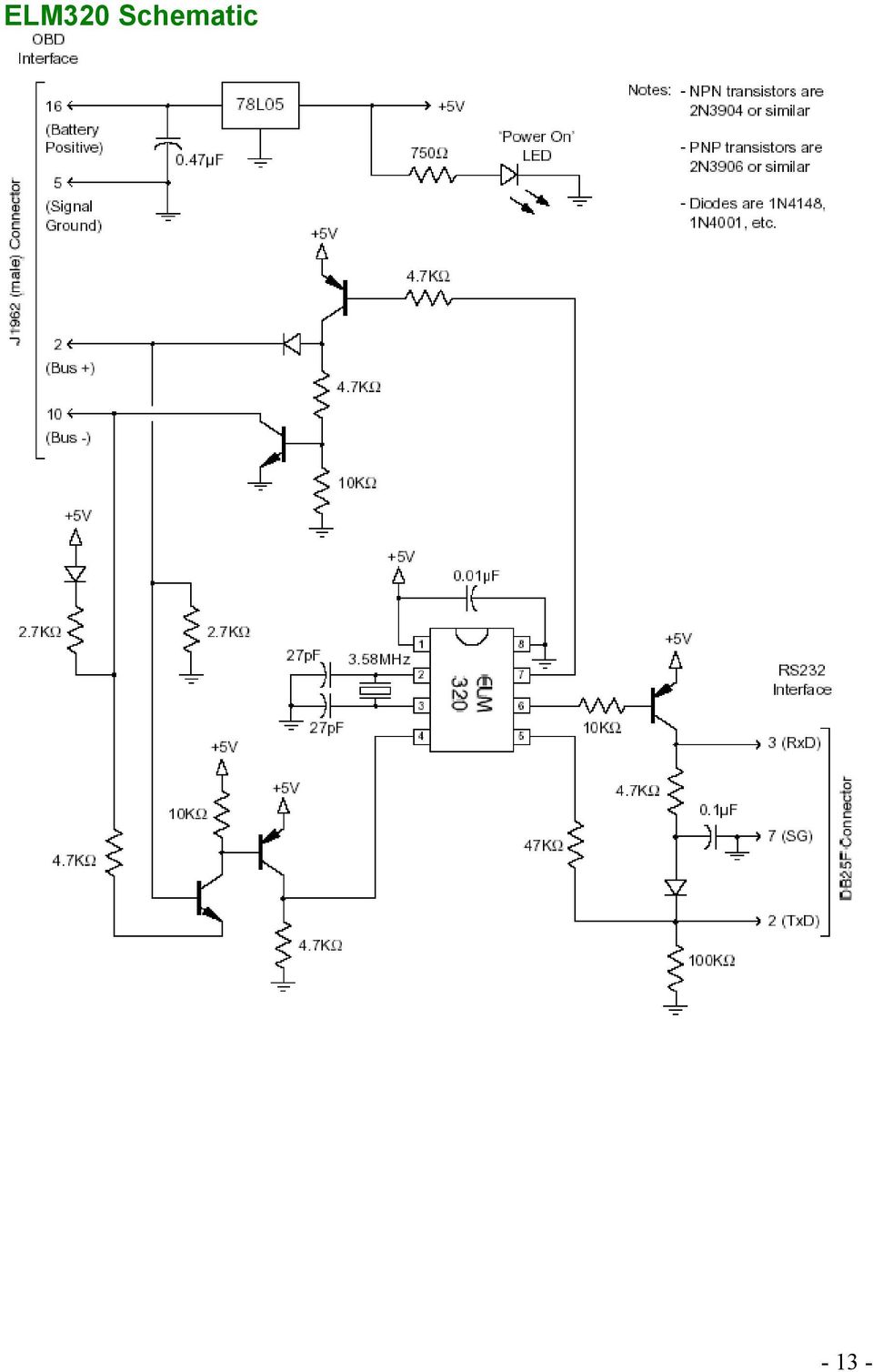
12 Appendix A DAS SOFTWARE The DAS software Windmill is freely available for download from their website OBDII to RS3 interpreter This device is used to read the data from your OBDII (1996 and newer) vehicle through a PC COM Port and ASCII commands. There are different protocols for FORD (PWM), GM (VPW), and other vehicles (ISO, CAN). You will need to determine which your vehicle uses. You can choose to build your own device or purchase one already built. Description Protocol Scantool.net ElmScan 5 USB Scan Tool All 41 ElmScan PWM Scan Tool PWM 4 ElmScan VPW Scan Tool VPW 43 ElmScan ISO USB ISO 45 The following list the parts and schematics for the three common type devices. OBDII - ELM PARTS LISTS ELM3 Data Sheet ELM-3 PARTS LIST Description QTY Allied Part # Scantool.net ELM 3 Chip DB5M to DB9F Cable (1ft) 1411 J196M to DB9F Cable Ohm kohm kohm kohm kohm kohm uf uf uf pf N N394 (NPN) N396 (PNP) v Voltage Regulator ICSOCKET/DIP MHz DB9RA/M DB5RA/F LED5MM/RED

13 ELM3 Schematic
14 ELM3 Data Sheet ELM-3 PARTS LIST Description QTY Allied Part # Scantool.net ELM 3 Chip 361 DB5M to DB9F Cable 88-1 (1ft) 1411 J196M to DB9F Cable Ohm Ohm, ½ Watt kohm kohm kohm kohm uf uf uf pf N N394 (NPN) N396 (PNP) v Voltage Regulator ICSOCKET/DIP MHz DB9RA/M DB5RA/F LED5MM/RED
 1 431-46 N396 (PNP) 568-93 +5v Voltage Regulator 1 568-965 ICSOCKET/DIP8 1 9-4 3.")
15 ELM3 Schematic

16 ELM33 Data Sheet ELM-33 PARTS LIST Description QTY Allied Part # Scantool.net ELM 33 Chip 3631 DB5M to DB9F Cable 88-1 (1ft) 1411 J196M to DB9F Cable Ohm kohm kohm kohm kohm kohm Ohm, ½ Watt Ohm uf uf uf pf N N394 (NPN) N396 (PNP) v Voltage Regulator ICSOCKET/DIP MHz DB9RA/M DB5RA/F LED5MM/RED LED5MM/GREEN LED5MM/YELLOW
 431-46 N396 (PNP) 568-93 +5v Voltage Regulator 1 568-965 ICSOCKET/DIP14 1 9-6 3.")
17 ELM33 Schematic

18 TESTING THE ELMSCAN UNIT APPENDIX B OBD- II Testing In order for you to access the data from your vehicle on your PC Laptop you will need to two vital pieces of information. A terminal program that can send ASCII commands to the ELMScan and the (PID) table that lists all the signal commands needed HEX DEC to request the appropriate data from the vehicle. Windows 1 1 comes with a terminal program called Hyper-Terminal that 3 3 you can use to send simple commands to the ELMScan in 4 4 ASCII format, however; the data returned is in HEX and has 5 5 several bits of information, you will need to understand this 6 6 data stream and convert to Decimal. 7 7 The Data sheet for the ELMScan Chipset explains in 8 8 detail what modes you can put the chipset in but for this 9 9 project we will focus on the show current data mode. This is signified by sending 1 out. Now this is meaningless unless you add the appropriate PID code for the specific data you are after, in our case we are looking for the Mass Air Flow (MAF) and Vehicle Speed Sensor (VSS). These PID s are 1 and D respectively. Therefore, to request the vehicle A B C D E F speed you would send the command 11 through the terminal program and would be returned: Send 1D return: Receive 41 D 37 This shows a mode 1 response (41) from PID D and the value is 37. The value is in HEX, to convert to Decimal multiply the first digit by 16 and add the second digit to reveal a value of 55 kilometers per hour. Hyper-Terminal is good for testing but in order to continuously receive updated real-time values a more powerful program is needed. There are many off the shelf programs out there that will do this for you, many are freeware and are provided when you purchase the ELMScan device or for download form their website. There is one problem with these programs; they do not offer real-time Miles per Gallon monitoring (I have found one program out there but this is a commercial version and costly). Beside, what fun is there if you buy everything already done? The Data Acquisition Software (DAS) I used to request the signals from the Vehicle Electronic Control Module (ECM) through the ELMScan hardware is named Windmill and is freely available from their website (

19 APPENDIX-C OBD-II PIDs Mode (hex) PID (hex) Data bytes returned Description Min Max value Units Formula value 1 4 PIDs supported Bit encoded [A7..D] == [PID x1..pid x] Number of trouble codes and I/M info Bit encoded. See below. 1 3 Fuel system status Bit encoded. See below Calculated engine load value 1 % A*1/ Engine coolant temperature C A Short term fuel % trim Bank 1-1 (lean) 99. (rich) %.781 * (A-18) Long term fuel % trim Bank 1-1 (lean) 99. (rich) %.781 * (A-18) Short term fuel % trim Bank -1 (lean) 99. (rich) %.781 * (A-18) Long term fuel % trim Bank -1 (lean) 99. (rich) %.781 * (A-18) 1 A 1 Fuel pressure 765 kpa (gauge) A*3 1 B 1 Intake manifold 55 kpa A
 99. (rich) %.")
20 pressure (absolute) 1 C Engine RPM 16, rpm ((A*56)+B)/4 1 D 1 Vehicle speed 55 km/h A 1 E 1 Timing advance relative to #1 cylinder A/ F 1 Intake air temperature C A MAF air flow rate g/s ((56*A)+B) / Throttle position 1 % A*1/ Sec.(?) air status Bit encoded. See below Oxygen sensors present [A..A3] == Bank 1, Sensors 1-4. [A4..A7] == Bank Bank 1, Sensor 1: Oxygen sensor voltage, Short term fuel trim Volts % A *.5 (B-18) *.781 (if B==xFF, sensor is not used in trim calc) 1 15 Bank 1, Sensor : Oxygen sensor voltage, Short term fuel trim Volts % A *.5 (B-18) *.781 (if B==xFF, sensor is not used in trim calc) - -
![See below. 1 13 1 Oxygen sensors present [A..A3] == Bank 1, Sensors 1-4. [A4..A7] == Bank... 1 14 Bank 1, Sensor 1: Oxygen sensor voltage, Short term fuel trim 1.75 99.](/docs-images/40/13657975/images/page_20.jpg "Volts % A *.5 (B-18) *.781 (if B==xFF, sensor is not used in trim calc) 1 15 Bank 1, Sensor : Oxygen sensor voltage, Short term fuel trim 1.75 99. Volts % A *.5 (B-18) *.781 (if B==xFF, sensor is not used in trim calc) - -")
21 1 16 Bank 1, Sensor 3: Oxygen sensor voltage, Short term fuel trim Volts % A *.5 (B-18) *.781 (if B==xFF, sensor is not used in trim calc) 1 17 Bank 1, Sensor 4: Oxygen sensor voltage, Short term fuel trim Volts % A *.5 (B-18) *.781 (if B==xFF, sensor is not used in trim calc) 1 18 Bank, Sensor 1: Oxygen sensor voltage, Short term fuel trim Volts % A *.5 (B-18) *.781 (if B==xFF, sensor is not used in trim calc) 1 19 Bank, Sensor : Oxygen sensor voltage, Short term fuel trim Volts % A *.5 (B-18) *.781 (if B==xFF, sensor is not used in trim calc) 1 1A Bank, Sensor 3: Oxygen sensor voltage, Short term fuel trim Volts % A *.5 (B-18) *.781 (if B==xFF, sensor is not used in trim calc) 1 1B Bank, Sensor 4: Oxygen sensor voltage, Short term fuel trim Volts % A *.5 (B-18) *.781 (if B==xFF, sensor is not used in trim calc) 1 1C 1 OBD standards this vehicle conforms to Bit encoded. See below. 1 1D 1 Oxygen sensors present Similar to PID 13, but [A..A7] == [B1S1, B1S, BS1, BS, B3S1, B3S, B4S1, B4S] 1 1E 1 Auxiliary input status A == Power Take Off (PTO) status (1 == - 1 -
22 active) [A1..A7] not used 1 1F Run time since engine start 65,535 seconds (A*56)+B 1 4 PIDs supported 1-4 Bit encoded [A7..D] == [PID x1..pid x4] 1 1 Distance traveled with malfunction indicator lamp (MIL) on 65,535 km (A*56)+B 1 Fuel Rail Pressure (relative to manifold vacuum) kpa ((A*56)+B) * Fuel Rail Pressure (diesel) kpa (gauge) ((A*56)+B) * OS1_WR_lambda(1): Voltage 8 V ((A*56)+B)*.35 ((C*56)+D)* OS_WR_lambda(1): Voltage 8 V ((A*56)+B)*.35 ((C*56)+D)* OS3_WR_lambda(1): Voltage 8 V ((A*56)+B)*.35 ((C*56)+D)* OS4_WR_lambda(1): Voltage 8 V ((A*56)+B)*.35 ((C*56)+D)* OS5_WR_lambda(1): 8 V ((A*56)+B)*.35 ((C*56)+D)*.1 - -
23 Voltage OS6_WR_lambda(1): Voltage 8 V ((A*56)+B)*.35 ((C*56)+D)*.1 1 A 4 OS7_WR_lambda(1): Voltage 8 V ((A*56)+B)*.35 ((C*56)+D)*.1 1 B 4 OS8_WR_lambda(1): Voltage 8 V ((A*56)+B)*.35 ((C*56)+D)*.1 1 C 1 Commanded EGR 1 % 1*A/55 1 D 1 EGR Error % A* E 1 Commanded evaporative purge 1 % 1*A/55 1 F 1 Fuel Level Input 1 % 1*A/ # of warm-ups since codes cleared 55 A 1 31 Distance traveled since codes cleared 65,535 km (A*56)+B 1 3 Evap. System Vapor Pressure -8,19 8,19 Pa ((A*56)+B)/4-8, Barometric pressure 55 kpa (Absolute) A - 3 -
24 OS1_WR_lambda(1): Current ma ((A*56)+B)*.35 ((C*56)+D)* OS_WR_lambda(1): Current ma ((A*56)+B)*.35 ((C*56)+D)* OS3_WR_lambda(1): Current ma ((A*56)+B)*.35 ((C*56)+D)* OS4_WR_lambda(1): Current ma ((A*56)+B)*.35 ((C*56)+D)* OS5_WR_lambda(1): Current ma ((A*56)+B)*.35 ((C*56)+D)* OS6_WR_lambda(1): Current ma ((A*56)+B)*.35 ((C*56)+D)* A 4 OS7_WR_lambda(1): Current ma ((A*56)+B)*.35 ((C*56)+D)* B 4 OS8_WR_lambda(1): Current ma ((A*56)+B)*.35 ((C*56)+D)* C Catalyst Temperature Bank 1, Sensor 1-4 6,513.5 C ((A*56)+B)/ D Catalyst Temperature Bank 1, Sensor -4 6,513.5 C ((A*56)+B)/
25 1 3E Catalyst Temperature Bank, Sensor 1-4 6,513.5 C ((A*56)+B)/ F Catalyst Temperature Bank, Sensor -4 6,513.5 C ((A*56)+B)/ PIDs supported 41-6 (?) Bit encoded [A7..D] == [PID x41..pid x6] (?) 1 41? Monitor status this drive cycle???? 1 4 Control module voltage V ((A*56)+B)/ Absolute load value 5696 % ((A*56)+B)*1/ Command equivalence ratio ((A*56)+B)* Relative throttle position 1 % A*1/ Ambient air temperature C A Absolute throttle position B 1 % A*1/ Absolute throttle position C 1 % A*1/ Accelerator pedal position D 1 % A*1/55 1 4A 1 Accelerator pedal 1 % A*1/55-5 -
26 position E 1 4B 1 Accelerator pedal position F 1 % A*1/55 1 4C 1 Commanded throttle actuator 1 % A*1/55 1 4D Time run with MIL on 65,535 minutes (A*56)+B 1 4E Time since trouble codes cleared 65,535 minutes (A*56)+B 1 C3????? Returns numerous data, including Drive Condition ID and Engine Speed* 1 C4????? B5 is Engine Idle Request B6 is Engine Stop Request* Freeze frame trouble code BCD encoded, see below. 3 n*6 Request trouble codes 3 codes per message frame, BCD encoded. See below. 4 Clear trouble codes / Malfunction indicator lamp (MIL) / Check engine light Clears all stored trouble codes and turns the MIL off. 9 5x5 Vehicle identification number (VIN) number Returns 5 lines, A is line ordering flag, B-E ASCII - 6 -
27 coded VIN digits
Global OBD Vehicle Communication Software Manual
 Global OBD Vehicle Communication Software Manual August 2013 EAZ0025B43C Rev. A Trademarks Snap-on is a trademark of Snap-on Incorporated. All other marks are trademarks or registered trademarks of their
SECURITY AND PRIVACY VULNERABILITIES OF IN-CAR WIRELESS NETWORKS CARLES FIGUEROLA
 SECURITY AND PRIVACY VULNERABILITIES OF IN-CAR WIRELESS NETWORKS BY CARLES FIGUEROLA Submitted in partial fulfillment of the requirements for the degree of Master Thesis in Electrical Engineering in the
Harrison R&D www.obdscan.net Houston, TX. OBDScan Manual Version March 22, 2005
 OBDScan Manual Version March 22, 2005 Congratulations for choosing the Harrison R&D OBDScan. We have made every attempt to insure your success with this product. Please take time to read through these
RA Automotive. Silver Scan-Tool for the testing of OBD functionality. Peter Stoß Senior Manager RA Automotive. Mai 2008
 RA Automotive Silver Scan-Tool for the testing of OBD functionality Peter Stoß Senior Manager RA Automotive RA Consulting GmbH Zeiloch 6a D-76646 Bruchsal Tel +49 (0)7251 3862-0 Fax +49 (0)7251 3862-11
Important: Always perform the Diagnostic System Check - Vehicle prior to using this diagnostic procedure. P0106, P0107 P0107
 Page 1 of 5 DTC P0106 DTC Descriptor 2006 Pontiac GTO GTO (VIN V) Service Manual Document ID: 1417869 DTC P0106: Manifold Absolute Pressure (MAP) Sensor Diagnostic Fault Information Important: Always perform
PC-Based Vehicle OBD Tester
 PC-Based Vehicle OBD Tester Presented by: Peter Dzhelekarski, M. Sc. Ph. D. Student at the Technical University of Sofia E-mail: pid@tu-sofia.bg Research director: Dimiter Alexiev, Assoc. Prof. Dr. Sofia
PEMS Conference. Acquiring Data from In-Vehicle Networks. Rick Walter, P.E. HEM Data Corporation
 PEMS Conference Acquiring Data from In-Vehicle Networks Rick Walter, P.E. HEM Data Corporation Acquiring Data from In-Vehicle Networks Topics Overview/Benefits Heavy Duty J1939 protocol Available J1939
New OBD Smart PC Tool User Manual
 New OBD Smart PC Tool User Manual V0.6 2013-07-30 1 / 16 Catalogue I Installation... 3 II Configuration... 3 2.1 Main interface... 4 2.2 Alarms... 6 2.3 Network... 8 2.4 Regular Report... 9 2.5 Others...
Emissions Readiness Monitor Strategies
 Emissions Readiness Monitor Strategies A presentation by NYS DMV s Office of Clean Air for New York State Automobile Dealers Association 10/30/2012 1 What is the payoff for mastering readiness monitor
DELLORTO. Instructions Manual. Deuss Service Tool For ECS System ECU. Dell Orto Deuss Service Tool instruction manual Page 1 of 11.
 DELLORTO Deuss Service Tool For ECS System ECU Instructions Manual Dell Orto Deuss Service Tool instruction manual Page 1 of 11 Revision History Level Date Author Change Description and section(s) affected
1. SAFETY PRECAUTIONS AND WARNINGS
 Table of Contents 1. SAFETY PRECAUTIONS AND WARNINGS...1 2. INTRODUCTION...3 2.1 On Board Diagnostics (OBD)...3 2.2 Vehicles Covered...4 2.3 Diagnostic Trouble Codes (DTCs)...6 2.4 Location of the Data
APPENDIX D PUBLIC AWARENESS INFORMATION
 APPENDIX D PUBLIC AWARENESS INFORMATION READINESS FAILURE FACT SHEET Beginning December 2004, New York will implement a new motor vehicle emission testing program in 53 of New York s upstate counties,
Volvo Vehicle Communications Software Manual
 Volvo Vehicle Communications Software Manual August 2013 EAZ0025B47A Rev. C Trademarks Snap-on is a trademark of Snap-on Incorporated. All other marks are trademarks or registered trademarks of their respective
DTC Database (OBD-II Trouble Codes)
") Auto Consulting S.a.s di Cofano A. & C. Attrezzature diagnostiche Elaborazioni elettroniche Formazione tecnica DTC Database (OBD-II Trouble Codes) Definitions for generic powertrain diagnostic trouble
Auto Consulting S.a.s di Cofano A. & C. Attrezzature diagnostiche Elaborazioni elettroniche Formazione tecnica DTC Database (OBD-II Trouble Codes) Definitions for generic powertrain diagnostic trouble
INTRODUCTION. 3 PARTS SUPPLIED. 3 BEFORE YOU BEGIN. 3 CONNECTING THE ECU INTERFACE TO OTHER EQUIPMENT. 11 DATA OUTPUT CHANNELS.
 Table of Contents INTRODUCTION... 3 PARTS SUPPLIED... 3 BEFORE YOU BEGIN... 3 CONNECTING THE ECU INTERFACE TO OTHER EQUIPMENT... 4 CONFIGURING A DATA LOGGER TO WORK WITH THE ECU INTERFACE... 11 DATA OUTPUT
ENGINE DIAGNOSTICS & CONTROL
 ENGINE DIAGNOSTICS & CONTROL CONTROL SYSTEM WIRING DIAGRAM Page 1 Page 2 MONITORING SYSTEM AND CONTROL SYSTEM DEVICE RELATIONSHIP CHART : Applicable Component Input Battery Ignition switch A/C switch,
ON-Board Diagnostic Trouble Codes
 ON-Board Diagnostic Trouble Codes The list below contains standard diagnostic trouble codes (DTC s) that are used by some manufacturers to identify vehicle problems. The codes provide below are generic
Table of Contents. 1.what is OBD2. 2. Product Information. 1. Safety Precautions and Warnings 1. obd2 was developed by the Califrnia Air Resources
 Table of Contents 1. Safety Precautions and Warnings 1 2. General Information 2.1 On-Board-Diagnostics (OBD )II 2 2.2 Diagnostic Trouble Codes (DTCs) 2 2.3 Location of the Data Link Connector (DTC) 3 2.4
Technical Service Information
 Technical Service Information COMPLAINT: CAUSE: 1996-20 DEFINITIONS When a VW/Audi vehicle is exhibiting a symptom or is in fail-safe, the technician, in many cases, is unable to communicate with the on-board
Throttle Body Fuel Injection
 Throttle Body Fuel Injection Initial Calibration of the TBI Disclaimer The author of this presentation assumes NO responsibility for information provided causing the owner to modify or alter their motorhome
EVAL-UFDC-1/UFDC-1M-16
 Evaluation Board for Universal Frequency-to- Digital Converters UFDC-1 and UFDC-1M-16 EVAL-UFDC-1/UFDC-1M-16 FEATURES Full-Featured Evaluation Board for the Universal Frequency-to-Digital Converters UFDC-1
Modern Robotics, Inc Core Device Discovery Utility. Modern Robotics Inc, 2015
 Modern Robotics, Inc Core Device Discovery Utility Modern Robotics Inc, 2015 Version 1.0.1 October 27, 2015 Core Device Discovery Application Guide The Core Device Discovery utility allows you to retrieve
MCB3101 (Class I) WiRobot Serial Bluetooth Wireless Module User Manual
 WiRobot Serial Bluetooth Wireless Module User Manual") MCB3101 (Class I) WiRobot Serial Bluetooth Wireless Module User Manual Version: 1.0.1 Dec. 2005 Table of Contents I. Introduction 2 II. Operations 2 II.1. Theory of Operation 2 II.2. Configuration (PC-PC
MCB3101 (Class I) WiRobot Serial Bluetooth Wireless Module User Manual Version: 1.0.1 Dec. 2005 Table of Contents I. Introduction 2 II. Operations 2 II.1. Theory of Operation 2 II.2. Configuration (PC-PC
LAND ROVER FUEL INJECTION SYSTEMS
 LAND ROVER FUEL INJECTION SYSTEMS INTRODUCTION Land Rover vehicles use one of two types of electronically controlled fuel injection systems: Multiport Fuel Injection (MFI) or Sequential Multiport Fuel
Monitor software for system A2 and W3
 Monitor software for system A2 and W3 S-E-G "System A2 Monitor" is a small utility for remote monitoring of S-E-G controllers from a PC. The software program requires connection to one or several A2 systems
Fault codes DM1. Industrial engines DC09, DC13, DC16. Marine engines DI09, DI13, DI16 INSTALLATION MANUAL. 03:10 Issue 5.0 en-gb 1
 Fault codes DM1 Industrial engines DC09, DC13, DC16 Marine engines DI09, DI13, DI16 03:10 Issue 5.0 en-gb 1 DM1...3 Abbreviations...3 Fault type identifier...3...4 03:10 Issue 5.0 en-gb 2 DM1 DM1 Fault
Powertrain DTC Summaries EOBD
 Powertrain DTC Summaries Quick Reference Diagnostic Guide Jaguar XJ Range V6, V8 N/A and V8 SC 2003.5 Model Year Refer to pages 2 9 for important information regarding the use of Powertrain DTC Summaries.
Final Year Project Report. An Embedded Automotive Monitoring Device. Automon
 Final Year Project Report An Embedded Automotive Monitoring Device Automon Submitted by Donal O' Connor Supervisor Tim Horgan In partial fulfilment of the requirements for the Degree of B.Sc. (Hons) Software
WA Manager Alarming System Management Software Windows 98, NT, XP, 2000 User Guide
 WA Manager Alarming System Management Software Windows 98, NT, XP, 2000 User Guide Version 2.1, 4/2010 Disclaimer While every effort has been made to ensure that the information in this guide is accurate
MANUAL FOR RX700 LR and NR
 MANUAL FOR RX700 LR and NR 2013, November 11 Revision/ updates Date, updates, and person Revision 1.2 03-12-2013, By Patrick M Affected pages, ETC ALL Content Revision/ updates... 1 Preface... 2 Technical
DTC P0125 Insufficient Coolant Temperature for Closed Loop Fuel Control
 EINE (5VZFE) DI195 DI8YY02 DTC P0125 Insufficient Coolant Temperature for Closed Loop Fuel Control CIRCUIT DESCRIPTION To obtain a high purification rate of the CO, HC and x components of the exhaust gas,
Module 21 Fuel Injectors - Dual Point Injection (DPI)
") Module 21 Fuel Injectors - Dual Point Injection (DPI) Author: Grant Swaim E-mail: sureseal@nr.infi.net URL: www.tech2tech.net Phone: (336) 632-9882 Fax: (336) 632-9688 Postal Address: Tech-2-Tech Website
Module 21 Fuel Injectors - Dual Point Injection (DPI) Author: Grant Swaim E-mail: sureseal@nr.infi.net URL: www.tech2tech.net Phone: (336) 632-9882 Fax: (336) 632-9688 Postal Address: Tech-2-Tech Website
PREPARATION FOR TESTING
 Table of Contents INTRODUCTION WHAT IS OBD?... 1 YOU CAN DO IT!... 2 SAFETY PRECAUTIONS SAFETY FIRST!... 3 ABOUT THE SCAN TOOL VEHICLES COVERED... 5 BATTERY REPLACEMENT... 6 SCAN TOOL CONTROLS CONTROLS
Driver Installation and Hyperterminal Operation of iload Digital USB Sensors
 Driver Installation and Hyperterminal Operation of iload Digital USB Sensors Driver Installation Insert the iload Digital USB Driver CD OR the LoadVUE or LoadVUE Lite CD into your computer s drive. If
ABOUT THE DIAGNOSTIC TOOL
 Table of Contents INTRODUCTION WHAT IS OBD?... 1 YOU CAN DO IT!... 2 SAFETY PRECAUTIONS SAFETY FIRST!... 3 ABOUT THE DIAGNOSTIC TOOL VEHICLES COVERED... 5 BATTERY REPLACEMENT... 6 DIAGNOSTIC TOOL CONTROLS
COMMON RAIL SYSTEM (CRS) SERVICE MANUAL: Operation
 SERVICE MANUAL: Operation") ISUZU ELF 4HK1/4JJ1 Engine COMMON RAIL SYSTEM (CRS) SERVICE MANUAL: Operation Issued : June 2007 Revised : July 2009 00400601EA 2009 DENSO CORPORATION All rights reserved. This material may not be reproduced
ISUZU ELF 4HK1/4JJ1 Engine COMMON RAIL SYSTEM (CRS) SERVICE MANUAL: Operation Issued : June 2007 Revised : July 2009 00400601EA 2009 DENSO CORPORATION All rights reserved. This material may not be reproduced
To perform Ethernet setup and communication verification, first perform RS232 setup and communication verification:
 PURPOSE Verify that communication is established for the following products programming option (488.2 compliant, SCPI only): DCS - M9C & DCS M130, DLM M9E & DLM-M9G & DLM M130, DHP - M9D, P series, SG,
NortechCommander Software Operating Manual MAN-00004 R6
 NortechCommander Software Operating Manual MAN-00004 R6 If the equipment described herein bears the symbol, the said equipment complies with the applicable European Union Directive and Standards mentioned
DTC Summaries. V8 AJ26 Engine Management 1997. Refer to page 2 for important information regarding the use of this Summary.
 DTC Summaries V8 AJ26 Engine Management 1997 OBD II MONITORING CONDITIONS: When testing for DTC reoccurrence, it can be determined if the Service Drive Cycle was of sufficient length by performing a PDU
ESE 498 Electrical Engineering Senior Design Final Project Report. Plug and Play Engine Sound Replicator
 ESE 498 Electrical Engineering Senior Design Final Project Report Plug and Play Engine Sound Replicator Whitney Flohr Electrical Engineering, Class of 2009 WMF1@cec.wustl.edu Jason Lin Electrica f 2009
SA-9600 Surface Area Software Manual
 SA-9600 Surface Area Software Manual Version 4.0 Introduction The operation and data Presentation of the SA-9600 Surface Area analyzer is performed using a Microsoft Windows based software package. The
SAS light Check Engine Malfunction Indicator Lamp
 SAS light Check Engine Malfunction Indicator Lamp Here's how to do it: In car ECM Diagnostics/ECM Reset procedure: 1) Sit in the driver's seat. 2) Turn the ignition key to the ON position and wait three
isppac-powr1220at8 I 2 C Hardware Verification Utility User s Guide
 November 2005 Introduction Application Note AN6067 The isppac -POWR1220AT8 device from Lattice is a full-featured second-generation Power Manager chip. As part of its feature set, this device supports
BMV-602 Data Link Manual
 BMV-602 Data Link Manual 1 Contents of the kit 1 x BMV-602 data link cable. 1 x Installation CD 2 System Requirements 2.1 Hardware requirements A BMV-602 with software version 2.03 or higher. A spare RS-232
Cat Electronic Technician 2015A v1.0 Product Status Report 4/20/2016 2:49 PM
 Page 1 of 19 Cat Electronic Technician 2015A v1.0 Product Status Report 2:49 PM Product Status Report Parameter Value Product ID WRK00337 Equipment ID WRK00337 Comments A01-52 C9 330D (THX37891) Parameter
The Answer to the 14 Most Frequently Asked Modbus Questions
 Modbus Frequently Asked Questions WP-34-REV0-0609-1/7 The Answer to the 14 Most Frequently Asked Modbus Questions Exactly what is Modbus? Modbus is an open serial communications protocol widely used in
Software Features of Auto Gas Gas Analyzer Features HC, CO, CO2, Lambda, Air Fuel, NOx. Has optional RPM and Oil Temp.
 Auto Gas Ultimate Model Shown Above Software Features of Auto Gas Gas Analyzer Features HC, CO, CO2, Lambda, Air Fuel, NOx. Has optional RPM and Oil Temp. Durable high strength aluminum case with all of
Accurate Measurement of the Mains Electricity Frequency
 Accurate Measurement of the Mains Electricity Frequency Dogan Ibrahim Near East University, Faculty of Engineering, Lefkosa, TRNC dogan@neu.edu.tr Abstract The frequency of the mains electricity supply
Module 6 Engine Control Module (ECM)
") Module 6 Engine Control Module (ECM) Author: Grant Swaim E-mail: sureseal@nr.infi.net URL: www.tech2tech.net Phone: (336) 632-9882 Fax: (336) 632-9688 Postal Address: Tech-2-Tech Website PO Box 18443 Greensboro,
Module 6 Engine Control Module (ECM) Author: Grant Swaim E-mail: sureseal@nr.infi.net URL: www.tech2tech.net Phone: (336) 632-9882 Fax: (336) 632-9688 Postal Address: Tech-2-Tech Website PO Box 18443 Greensboro,
Global Monitoring + Support
 Use HyperTerminal to access your Global Monitoring Units View and edit configuration settings View live data Download recorded data for use in Excel and other applications HyperTerminal is one of many
Quick Start Guide RRL Radio Telemetry
 Quick Start Guide RRL Radio Telemetry Antenna External Power Connection LED Activity Light RS232 Connection Serial Number Levelogger Connections RRL Station High Quality Groundwater and Surface Water Monitoring
User Guide. Vehicle Diagnostics by Delphi
 User Guide Vehicle Diagnostics by Delphi Table Of Contents Welcome...9 Is My Vehicle Compatible?...9 Equipment Overview...10 Package Contents...10 System Requirements...11 Installation Requirements...11
PC SERIAL INTERFACE FOR LAMBDA GAS CONTROL LGC-700
 PC SERIAL INTERFACE FOR LAMBDA GAS CONTROL LGC-700 INDEX 1- Introduction 2- AGI-PRO Program Set-up 3- AGI-PRO Program Use 3.1- Interface Link 3.2- How Start AGI-PRO program 3.2-1. Page MONITOR 3.2-2. Page
Part Number Description Packages available
 Features 3 digital I/O Serial Data output Connects directly to RF Modules Easy Enc / Dec Pairing Function Minimal External Components Required Performs all encoding/decoding of data for Reliable Operation.
User s Manual. USB AutoTap / Serial AutoTap. This product designed and manufactured in Ottawa, Illinois USA by. 1998-2005 B&B Electronics Mfg. Co.
 User s Manual USB AutoTap / Serial AutoTap This product designed and manufactured in Ottawa, Illinois USA by 1998-2005 B&B Electronics Mfg. Co. Documentation Number: AT-3105 Manual TABLE OF CONTENTS How
WinLIN Setup and Operation:
 Frequently Asked Questions about the 07551-Series Masterflex L/S Computer-Compatible drives and about the Masterflex WinLIN Linkable Instrument Control Software (07551-70) WinLIN Setup and Operation: Will
Diagnostics Scanner RAC-HP104
 Diagnostics Scanner RAC-HP104 Environmental Protection Waste electrical products should not be disposed of with household waste. Please recycle where facilities exist. Check with your local authority or
SenseLink TM. End-Point Controller. Addendum
 SenseLink TM End-Point Controller Addendum MKS Instruments, Inc. Control & Information Technology Products Group 3350 Scott Blvd Bldg 4 Santa Clara, CA 95054 Main: 408.235.7620 Fax: 408.235.7625 SenseLink
Technical Specifications: The specifications represent a particular hardware platform. Application-specific software is provided.
 Preliminary TECHNICAL DATASHEET #TDAX020700 HYDRAULIC VALVE CONTROLLER 24 I/O 5 Analog and 6 Digital Inputs 1 Temperature Sensor and 1 RPM Sensor Interface 2 PWM Inputs 6 Proportional and 4 ON/OFF Current
Automotive Sensor Simulator. Automotive sensor simulator. Operating manual. AutoSim
 Automotive sensor simulator Operating manual AutoSim Contents Introduction.. page 3 Technical specifications.... page 4 Typical application of AutoSim simulator..... page 4 Device appearance... page 5
Synergy Controller Application Note 4 March 2012, Revision F Tidal Engineering Corporation 2012. Synergy Controller Bar Code Reader Applications
 Synergy Controller Bar Code Reader Applications Synergy Controller with Hand Held Products Bar Code Scanner OCR-A Labeled Part Introduction The value of the ubiquitous Bar Code Scanner for speeding data
WIFI OBD GPS Tracker T356 User Manual
 WIFI OBD GPS Tracker T356 User Manual Version:1.000 http://www.ulbotech.com mkt@ulbotech.com Document Title T356 User Manual Version 1.000 Date 2015-04-02 Status Release General Notes Ulbotech offers this
F453. TiF453. User guide 10/11-01 PC
 F453 TiF453 User guide 10/11-01 PC 2 TiF453 User guide Contents 1. Hardware and Software requirements 4 2. Installation 4 1.1 Minimum Hardware requirements 4 1.2 Minimum Software requirements 4 3. Fundamental
The On-Board Refueling Vapor Recovery (ORVR) Evaporative Emission (EVAP) system.
 Evaporative Emission (EVAP) system.") «1A: Description and Operation» Overview The Evaporative Emission (EVAP) system prevents fuel vapor build-up in the sealed fuel tank. Fuel vapors trapped in the sealed tank are vented through the vapor
«1A: Description and Operation» Overview The Evaporative Emission (EVAP) system prevents fuel vapor build-up in the sealed fuel tank. Fuel vapors trapped in the sealed tank are vented through the vapor
Volvo Parts Corporation 04-02-03 Volvo Trip Manager. Contents
 User s Manual Contents Functional Overview...4 Welcome to Volvo Trip Manager...4 About the documentation...4 Information Downloading...5 Vehicle Groups...6 Warning Messages...6 Reports...7 Trend Report...7
Lotus Service Notes Section EMP
 ENGINE MANAGEMENT SECTION EMP Sub-Section Page Diagnostic Trouble Code List EMP.1 3 'Lotus Scan' Diagnostic Tool EMP.2 43 Engine Management Component Location EMP.3 45 Mechanical Throttle Setting Procedure
Trucks. Group 28 Release1. Engine Control Module (ECM), AftertreatmentControlModule (ACM), VMAC IV Diagnostic Trouble Code (DTC)
, AftertreatmentControlModule (ACM), VMAC IV Diagnostic Trouble Code (DTC)") ServiceInformation Trucks Group 28 Release1 Engine Control Module (ECM), AftertreatmentControlModule (ACM), VMAC IV Diagnostic Trouble Code () 89091093 Foreword The descriptions and service procedures
ServiceInformation Trucks Group 28 Release1 Engine Control Module (ECM), AftertreatmentControlModule (ACM), VMAC IV Diagnostic Trouble Code () 89091093 Foreword The descriptions and service procedures
Lotus Service Notes Section EMR
 ENGINE MANAGEMENT SECTION EMR Sub-Section Page Diagnostic Trouble Code List EMR.1 3 Component Function EMR.2 7 Component Location EMR.3 9 Diagnostic Guide EMR.4 11 CAN Bus Diagnostics; Lotus TechCentre
DIAGNOSIS SYSTEM (3S GTE and 5S FE)
") Diagnosis System (3SGTE and 5SFE) FI39 DIAGNOSIS SYSTEM (3SGTE and 5SFE) DESCRIPTION The ECM contains a builtin, selfdiagnosis system by which troubles with the engine signal network are detected and a
Diagnosis System (3SGTE and 5SFE) FI39 DIAGNOSIS SYSTEM (3SGTE and 5SFE) DESCRIPTION The ECM contains a builtin, selfdiagnosis system by which troubles with the engine signal network are detected and a
GPS Vehicle and personal location tracker. User manual
 GPS Vehicle and personal location tracker User manual 1 Contents 1. Product overview... 2 2. Safety instruction... 3 3. Specification and parameters... 3 4. Getting started... 4 4.1 Hardware and accessories...
Cart Interface Installation & Control Board Manual for M38 XP and RX Carts and Legacy M39 Carts
 Rubbermaid Medical Solutions Cart Interface Installation & Control Board Manual for M38 XP and RX Carts and Legacy M39 Carts REVISED FEBRUARY 25, 2010 Filename: Cart Interface Installation & Control Board
VOLKSWAGEN POWERTRAIN CONTROL SYSTEMS DIAGNOSTICS ONE
 LEARNING GUIDE POWERTRAIN SPECIALIST VOLKSWAGEN POWERTRAIN CONTROL SYSTEMS DIAGNOSTICS ONE COURSE NUMBER: PT310-01 Notice Due to the wide range of vehicles makes and models, the information given during
Introduction to Electronic Signals
 Introduction to Electronic Signals Oscilloscope An oscilloscope displays voltage changes over time. Use an oscilloscope to view analog and digital signals when required during circuit diagnosis. Fig. 6-01
BTMPico Data Management Software
 BTMPico Data Management Software User Manual Version: 1.3 for S/W version 1.16F or higher 2013-04-26 Page 1 of 22 Table of Contents 1 Introduction 3 2 Summary 5 3 Installation 7 4 Program settings 8 5
Automation System TROVIS 6400 TROVIS 6493 Compact Controller
 Automation System TROVIS 6400 TROVIS 6493 Compact Controller For panel mounting (front frame 48 x 96 mm/1.89 x 3.78 inch) Application Digital controller to automate industrial and process plants for general
QUICK START GUIDE 199R10546
 QUICK START GUIDE 199R10546 1.0 Overview This contains detailed information on how to use Holley EFI software and perform tuning that is included within the software itself. Once you load the software,
Signature and ISX CM870 Electronics
 Signature and ISX CM870 Electronics Cummins West Training Center System Description General Information The Signature and ISX CM870 engine control system is an electronically operated fuel control system
Different Ways of Connecting to. 3DLevelScanner II. A.P.M Automation Solutions LTD. www.apm-solutions.com Version 3.0
 3DLevelScanner II Different Ways of Connecting to 3DLevelScanner II A.P.M Automation Solutions LTD. www.apm-solutions.com Version 3.0 2 Different Ways of Connecting to 3DLevelScanner II Version 3.0 Table
QUICK TUNE EFI INSTRUCTION MANUAL
 QUICK TUNE EFI INSTRUCTION MANUAL Step 1: Loading the CB quick Tune Software to your PC A) Take the CB Quick Tune installation CD and load it into your PC. A window will pop up asking to have all programs
2001 MY OBD System Operation Summary for 7.3L Diesel Engine
 2001 MY OBD System Operation Summary for 7.3L Diesel Engine Table of Contents Introduction OBD-I and OBD-II... 2 OBD-II Systems...2 OBD-I Systems...2 Misfire Monitor... 3 Low Data Rate System...3 Misfire
1.Eastron SDM220Modbus Smart Meter Modbus Protocol Implementation V1.0
 1.Eastron SDM220Modbus Smart Meter Modbus Protocol Implementation V1.0 1.1 Modbus Protocol Overview This section provides basic information for interfacing the Eastron Smart meter to a Modbus Protocol
DESCRIPTION. DTC P0351 Ignition Coil "A" Primary / Secondary Circuit. DTC P0352 Ignition Coil "B" Primary / Secondary Circuit
 1 of 10 6/4/2012 10:38 PM Last Modified: 3-27-2012 6.4 C From: 201203 Model Year: 2013 Model: FR-S Doc ID: RM000000XH40PUX Title: FA20 ENGINE CONTROL: SFI SYSTEM: P0351-P0354: Ignition Coil "A" Primary
Driveability Diagnostics, OBD I & II
 Driveability Diagnostics, OBD I & II By Steve Zack - SPX Technical Trainer and Technical Specialist, JA Echols & Assoc Since the dawn of on-board diagnostics (OBD) in motor vehicles, the process of diagnosing
Evaporative emissions system
 just a test. Evaporative emissions system 20-48 Function description of EVAP canister system Depending upon the air pressure and ambient temperature, fuel vapor will form above the level of fuel in the
ScanWin Installation and Windows 7-64 bit operating system
 ScanWin Installation and Windows 7-64 bit operating system In order to run the ScanWin Pro install and program on Windows 7 64 bit operating system you need to install a Virtual PC and then install a valid,
Electronic Power Control
 Service. Self-Study Programme 210 Electronic Power Control Design and Function With the Electronic Power Control system, the throttle valve is actuated only by an electric motor. This eliminates the need
Productivity Software Features
 O P E R A T I O N S A N D P R O C E D U R E S F O R T H E P R O D U C T I V I T Y S O F T W A R E Productivity Software Features Remote CS-230 calibration and set-up on a personal computer. CS-230 calibration
Cat Electronic Technician 2015C v1.0 Product Status Report 2/20/2016 4:34 PM
 Cat Electronic Technician 2015C v1.0 Product Status Report 2/20/2016 4:34 PM Product Status Report Parameter Product ID Equipment ID Comments Value JGB00714 NOT PROGRAMMED Machine Control 345D (JGB00714)
LT1 Tune Kit Quick Start Guide
 LT1 Tune Kit Quick Start Guide Revision D Page 1 Table of Contents Introduction... 3 Minimum PC Requirements... 3 Program Installation... 3 Registering the Program... 4 Installing the USB/ALDL Interface
Scan Tool Test Procedures Steve Zack - SPX. Scan Tool Test Procedures
 Scan Tool Test Procedures Steve Zack - SPX Scan Tool Test Procedures Steve Zack - SPX 1 PCM Input Tests While performing many of these tests, to obtain the fastest possible Datastream refresh rate, please
ENGINE CONTROLS AND FUEL SYSTEMS
 ENGINE CONTROLS AND FUEL SYSTEMS SPRING 2005 FORD VEHICLE COMPUTER RELEARN PROCEDURES Performing repairs or service on any of the following may require you to initiate a computer relearn procedure in order
Intervid Fleet Management Fleet Telematics. Intervid, Inc. 5111 Pegasus Court, Suite C Frederick, MD 21704
 Intervid Fleet Management Fleet Telematics Intervid Fleet Management Intervid Fleet Management brings to market a leading Global Fleet Telematics Technology. Intervid Fleet Management solutions have assisted
TP- 051 GPS RECEIVER
 TP- 051 GPS RECEIVER CONTENTS 1. Overview 3 2. Features 3 3. The advantages of TP-051 GPS Receiver 4 4. The appearance and structures 4 5. Applications 5 6. Installation steps for the TP-051 GPS Receiver
SETTING UP A REMOTE MODEM CONNECTION Application Note 27
 SETTING UP A REMOTE MODEM CONNECTION Application Note 27 with WeatherLink for Windows Serial Version Only INTRODUCTION This document provides guidelines on how to set up a remote modem connection. This
ABB i-bus EIB / KNX Analogue Input AE/S 4.2
 Product Manual ABB i-bus EIB / KNX Analogue Input AE/S 4.2 Intelligent Installation Systems This manual describes the functionality of Analogue Input AE/S 4.2. Subject to changes and errors excepted. Exclusion
TCP/IP MODULE CA-ETHR-A INSTALLATION MANUAL
 TCP/IP MODULE CA-ETHR-A INSTALLATION MANUAL w w w. c d v g r o u p. c o m CA-ETHR-A: TCP/IP Module Installation Manual Page Table of Contents Introduction...5 Hardware Components... 6 Technical Specifications...
 Control Technology Corporation CTC Monitor User Guide Doc. No. MAN-1030A Copyright 2001 Control Technology Corporation All Rights Reserved Printed in USA The information in this document is subject to
BINARY EDITOR GETTING STARTED
 BINARY EDITOR GETTING STARTED AUTHOR DATE REVISION Clint Garrity 12 Aug 2009 A TABLE OF CONTENTS MODIFICATIONS TO THE DOCUMENT...3 1 INTRODUCTION...4 1.1 Scope... 4 1.2 Structure... 4 1.3 Definitions...
Gen III - Speed Density VE Table and MAF Tuning Instructions with a Wideband O2 Sensor Create by 69lt1bird Jeff Anderson
 These instructions are written for the beginner and intermediate user of HP Tuners software. A wideband O2 sensor is required for the tuning described in these procedures. If you have upgraded your fuel
User Manual. AS-Interface Programmer
 AS-Interface Programmer Notice: RESTRICTIONS THE ZMD AS-INTERFACE PROGRAMMER HARDWARE AND ZMD AS-INTERFACE PROGRAMMER SOFTWARE IS DESIGNED FOR IC EVALUATION, LABORATORY SETUP AND MODULE DEVELOPMENT ONLY.