MOVFR ELECTRICAL ADJUSTMENTS. G.A.L. MFG. CORP. NEW YORK CITY U.S.A.
|
|
|
- Collin Howard
- 8 years ago
- Views:
Transcription
1 MOVFR ELECTRICAL ADJUSTMENTS G.A.L. MFG. CORP. NEW YORK CITY U.S.A. 1

2 ELECTRICAL ADJUSTMENTS ADJUSTING INSTRUCTIONS FOR THE G.A.L. VARIABLE FREQUENCY CLOSED LOOP DOOR OPERATOR TYPE MOVFR 7.1 OVERVIEW: The MOVFR is a 230VAC door operator. It is controlled by a variable voltage, variable frequency (VVVF) closed loop drive. The control includes an AC ½ HP Motor, a VVVF Drive, and a PC board. It features keypad programming with digital display, door position optical cams, sequential Light Emitting Diodes (LED) for door speed positions, obstruction detection signal, and DPM Fault Monitor* signal. A Heavy Door Input, and an Auxiliary Cam are also available, when needed. MOVFR accepts universal input control signals from dry contacts to signal voltages, from 24 to 230V AC or DC**. The output contacts rated at 10Amp, 230VAC, and they are: Door Close Limit (DCL), Door Open Limit (DOL), Re-Open (RE- OPEN), Door Protection Monitor (DPM), and Auxiliary (AUX) *: The Fault Monitor is a G.A.L. patented door lock and gate switch protection device. Its purpose is to meet the ASME A17.1 RULE and CAN/CSA-B44-M90 RULE *: If the input signal voltage is 60 volts or less, the input board resistor must be cut (see connection diagram Dwg. No. 8032). 7.2 ADJUSTMENT AIDS: Switches, LED pilot lights and a Parameter Unit are available to aid the adjustment of the operator (see Figure 7.2.A). A. Five toggle switches are provided to facilitate the adjusting procedure as describe below: 1. RUN/CAM SETUP switch. The RUN position is for normal operation. The CAM SETUP position allows adjusting the cams and turning on the appropriate pilot lights without applying power to the motor. 2. AUTO/MAN. switch. The AUTO position is for normal operation. The MAN. position allows opening and closing the door by means of the OPEN/CLOSE switch. 3. OPEN/CLOSE switch allows constant pressure opening and closing when the AUTO/MAN. switch is in the MAN. position. 4. NUDG. switch allows closing the door at a reduced speed (nudging speed) when the AUTO/MAN. is in the MAN. position and constant pressure is applied to CLOSE position and NUDG position of the OPEN/CLOSE and NUDG switches respectively. 5. HEAVY/RESET switch. When the AUTO/MAN. switch is in the MAN. position, if a constant pressure is applied to the HEAVY position, it will work in conjunction with OPEN/CLOSE, NUDG. switches to open, close, or nudge the door. The RESET position allows manual reset of faults of the drive. On the drive, the Green LED indicates drive has power, the Red LED indicates an alarm has occurred and shutdown the drive. If this occurs, make a visual inspection of the door, and if there are no visible problems, place the AUTO/MAN. switch in the MAN. position, apply pressure to the RESET position of the HEAVY/RESET switch then release. Operate the door with the OPEN/CLOSE switch. Making sure that all is clear before returning to AUTO mode. Use the Parameter unit to view the Alarm history. 2

3 Figure 7.2.A B. LED pilot lights: A Red LED is provided on each of the four input boards (open, close, nudg., heavy). Heavy input is optional. As mentioned earlier, the input board resistor must be cut if the inputs signal voltage is 60 volts or less (see Figure 7.2.B.1). Red LEDs for Inputs control signal Indicator. The input resistors must be cut if the inputs signal voltage is 60V or less Figure 7.2.B.1 3

4 There are 16 more LED lights are provided to indicate the position of the speed cams, limit cams and modes of operation. When a cam blocks an optical sensor, the function is activated and the corresponding LED light turns on (see Figure 7.2.B.2). The 16 LED lights are: 1. HSC: High Speed Close. 2. FSC: Final Speed Close. 3. DCL: Door Close Limit (DCL output relay is energized when the DCL LED light turns on). 4. SSO: Slow Start Open. 5. HSO: High Speed Open. 6. MSO: Medium Speed Open. 7. FSO: Final Speed Open. Note: The combination of Cam#1(SSO/FSO) and Cam#2(MSO) produces SSO, HSO, MSO, and FSO. See 7.7 CAM SETTINGS VS. DISTANCE for appropriate settings. 8. DOL: Door Open Limit (DOL output relay is energized when the DOL LED light turns on). 9. HOLDING: Door is in its full open or full close position. (When the door is fully open or fully closed, a minimal amount of power is applied to the motor to prevent drifting). 10. NUDG. Door is closing at reduced speed (nudging). 11. RE-OPEN: Door re-opening features have activated. (RE-OPEN output relay is energized when the RE-OPEN LED light turns on). 12. STALL REVERSE: In the close direction, if the door exceeds the Torque Limit set by Par. 9, the STALL REVERSE LED will turn on and the RE-OPEN relay will be energized). 13. FREQ. FAILURE: In the close direction, if the door exceeds the Speed Limit set by Par. 0, the FREQ. FAILURE LED will turn on and the RE-OPEN relay will be energized). 14. DPM: A car door closed contact for safety features such as G.A.L. Fault monitor. (DPM relay is energized when the DPM LED light turns on). 15. FAULT: The FAULT LED on indicates that there is a Fault in the drive. 16. AUX.: The AUX. LED and the AUX. relay will turn on when AUX cam is activated. AUX. cam and AUX. cam are optional and available upon request. Figure 7.2.B.2 4
 and Cam#2(MSO) produces SSO, HSO, MSO, and FSO. See 7.7 CAM SETTINGS VS. DISTANCE for appropriate settings. 8.")
5 C. Parameter Unit: The Parameter Unit plugs into the Drive and permits changing values of pertinent parameters (see Figure 7.4 ). 7.3 PRELIMINARY CHECKS: This procedure is to assure that the motor turns in the correct direction, and all speed signals are in the working order. A. Place the RUN/CAM SETUP switch in the RUN position and place the AUTO/MAN switch in the MAN. Position. B. With the door fully closed, hold the OPEN/CLOSE switch in the OPEN position while observing the door movement. If the motor turns in the wrong direction, turn Power OFF, swap any two of the three motor leads. The door should change speed as the various cams operate the speed controlling speed sensors. The door should start moving at low speed with the SSO sensor blocked and then accelerate to high Speed (HSO) as the SSO sensor is unblocked. Deceleration takes place when the MSO sensor is blocked, then more deceleration with the FSO sensor is blocked, and finally the DOL sensor is blocked and the HOLDING LED turns on. A little power will apply to the motor to hold doors open. When the door is fully open, hold the switch in the CLOSE position, the door should start accelerating To high speed (HSC) and then decelerating as the FSC sensor is blocked. Finally the DCL sensor is blocked and the HOLDING LED turns on. Again, a little power will apply to the motor to hold doors open. (See 7.7 CAM SETTING VS. DISTANCE). 5

6 7.4 THE PARAMETER UNIT: The Parameter unit is a tool to assist users in the following tasks: - Changing speed values, acceleration, deceleration, torque, maximum closing speed, carrier frequency, and stall reverse limit. - Downloading, and Uploading Programs to and from the Drives. - Monitoring Currents, Voltages, Speeds, Inputs, Outputs, and Faults. - Resetting the Drive. Figure PARAMETER UNIT NAVIGATION: I. HOW TO CHANGE PARAMETERS:. Enter a Parameter Number.. Enter a new Value. Wait for the Completed Signal from the Display. II. HOW TO READ (COPY) FROM THE DRIVE: NOTE 1 : The Parameter Unit is capable to store 4 Sets of Default Parameters and 1 Set of Working Parameters. To Copy a Default Set of Parameters into the Working Set Parameters, see item 8 th of Section VI. NOTE 2 : To Transfer data from one drive to another, users must, First, READ(COPY) from the First Drive.. Wait for the Completed Signal from the Display. III. HOW TO WRITE (DOWNLOAD) TO THE DRIVE: Set RUN/CAM SETUP switch to CAM SETUP.. Wait for the Completed Signal from the Display. 6
 FROM THE DRIVE: NOTE 1 : The Parameter Unit is capable to store 4 Sets of Default Parameters and 1 Set of Working Parameters.")
7 IV. DEFAULT SETTINGS FOR THE MOVFR DRIVE: 7

8 V. CONVENIENT KEYS: to check the Speed in Hz Example: to check Input & Output Signals. Inputs: Z: (Reserved) C: Door Close O: Door Open R: Reset V: Heavy Door L: Control Bit L M: Control Bit M H: Control Bit H Outputs: S: Over Speed T: Over Torque F: Fault Example: to check the recent Faults. or to view all the Faults Example: to check the Output Voltage. Example: to check the Output Current. to Reset the Drive. VI. THE KEYS: the key will allow users to view, change, and reset to G.A.L. Default parameters. or to navigate through all the items in the VIEW section. to view an item. At any time, to get back to the Previous Display. 8

9 5 th The User List includes all the DEFAULT SETTINGS FOR THE MOVFR DRIVE in part IV. 1 st. Displays the Output Voltage, Output Current, Command Speed, and Actual Speed. 2 nd. Displays the Input and Output Signals = Activate = Deactivate (See the CONVENIENT KEYS in part V) 3 rd.. (See the CONVENIENT KEYS in part V) or to View all the Faults. 4 th. There are 2 Counters. Counter 1 will count up to 9,999 times. Counter 2 will count up to 60,000 times. When Counter 1 reaches 9999,Counter 2 will increase 1 The total count will be 600,000,000 times. or to View Counter 1 or Counter 2. or to view all the Parameters in the User List. to get in a Parameter in the List. NOTE: Users can alsochange the Value of Parameters in this stage by entering a new Value and to get back to the Previous Display. 6 th. to view the Maximum Closing Speed. to get back to the Previous Display. 7 th. to view the Maximum Closing Force. to get back to the Previous Display. 8 th., or to pick one of the four sets of Parameters Set RUN/CAM SETUP switch to CAM SETUP to copy the chosen set of Parameters to the Working Set of Parameters. 9

10 VI. CONVENIENT KEYS: There are 7 LEDs on the Parameter Unit. DO, DC, NUD, HLD, PRG, FLT, OVT. DO= Door Open, DC= Door Close, NUD=Nudging, HLD= Holding, PRG= Programming Mode, FLT= Fault, OVT= Over Torque. These LEDs indicate the present status of the MOVFR 7.6 PARAMETER ADJUSTMENTS: CAUTION! All equipment must be installed and adjusted to meet Federal, State, and Local Codes. NOTE 1: NOTE 2: NOTE 3: The closing Kinetic Energy is affected by the speed and the mass of the door. The closing Kinetic Energy must not exceed Code Limits. For more details about the Kinetic Energy of the G.A.L door operators, go to The closing Torque is affected by the Torque adjustment. The closing Torque must not exceed Code Limits. Whenever changing any value in the Closing Direction Parameters, the door should be rechecked to meet the Code requirement. A. CLOSING SEQUENCE: MAXIMUM CLOSE SPEED (Par. 0): This Parameter is the Limit of the Closing speed. The Default value of this Parameter is 30Hz. If the Closing speed is higher than 30Hz, the Drive will turn on the Frequency Failure (FF) output and activate the Reopen Relay. Users should bear in mind that the Reopen Relay Contact, once activated, will send the re-open signal to the Main Controller ONLY and will wait for the OPEN signal from the Main Controller to Reopen the door. The Reopen Relay will NOT reopen the door by itself. HOLDING TORQUE (Par. 1): The Holding Torque is activated when the door reaches DOL or DCL. HOLDING SPEED (Par. 2): The Holding Speed is activated when the door reaches DOL or DCL. NOTE: The reason to apply the Holding Power when the door is fully closed or fully open is to prevent the door from drifting or rolling back. CAUTION! The Holding power should be less than 15W to prevent the motor from unnecessary heating, which would reduce its life. 10

11 HIGH SPEED CLOSE HSC (Par. 4): This is the highest speed for the overall Closing sequence. A higher value produces the faster speed. FINAL SPEED CLOSE FSC (Par. 5): This is the Final Closing Speed. It should be set reasonably low so that when the DCL (Door Close Limit) and the Close Stop Roller are reached without slamming or bouncing. NUDGING SPEED (Par. 6): The Nudging Speed is the reduced speed that is equal or less than 60% of the max. HSC. This Nudging Speed is only occurred when DC (Door Close) and NUDG. (Nudging) input signals take place simultaneously CLOSE ACCELERATION TIME (Par. 7): The higher value produces a slower acceleration rate for smoother operation. The lower value produces a faster acceleration rate for faster opening times. CLOSE DECELERATION TIME (Par. 8): The Deceleration should be set so that the FSC is reached prior to the DCL and the Close Stop Roller position without bouncing. STALL REVERSE FORCE (Par. 9): The Default value of this Parameter is 1.5Amp. Whenever the current is above this value, the Drive will send a signal to turn on the STALL REVERSE LED and activate the REOPEN Relay. The range for this Parameter is 0-2Amp. If nuisance activation takes place, the value of this Parameter should be increase slightly. OVERLOAD (Par. 99) This is the Maximum Limit of the Motor Current. If the Motor Current exceeds this Limit, the Drive will shutdown, generate the OVER CURRENT FAULT, and turn on the FAULT LED. Recycling the Power to MOVFR or using the Reset switch on the Main Board or the Parameter Unit will Reset the Fault. However, a thorough inspection should be done before Resetting the Fault. B. OPENING SEQUENCE: QUICK STOP ON REVERSE (Par. 21): Parameter 21 determines how quick the closing door is stopped when a reopen signal is activated. The range of Parameter 21 is from 0 to 6Amp. The lower value setting will produce a longer time to stop before the door can reopen. When the reopen signal is applied, the door should not move more than 2 inches before it reopens. (Note: too quick of a stop will degrade the doors mechanicals) SLOW START OPEN SSO (Par. 22): When the door starts to open, the value of Par. 22 is the speed at which the clutch engages the interlock rollers unlock the hoistway door. A slower speed produces a smoother and quieter unlocking noise. HIGH SPEED OPEN HSO (Par. 23): This is the highest speed for the overall opening sequence. The higher value produces a faster speed. MEDIUM SPEED OPEN MSO (Par. 24): This speed is used for a fast reopening in the final 1/3 to 1/4 of the opening. When properly adjusted, this speed has little or no effect during the full reopening cycle because the doors will decelerate through MSO zone. Virtually the doors will decelerate from HSO to FSO. 11
 input signals take place simultaneously CLOSE ACCELERATION TIME (Par. 7): The higher value produces a slower acceleration rate for smoother operation.")
12 FINAL SPEED OPEN FSO (Par. 25) This is the Final Opening Speed. It should be set reasonably low so that the DOL (Door Open Limit) and the Open Stop Roller are reached without slamming or bouncing. OPEN ACCELERATION TIME (Par. 26). The higher value produces a slower acceleration rate for smoother operation. The lower value produces a faster acceleration rate for faster opening times. OPEN DECELERATION TIME (Par. 27). The Deceleration should be set so that the FSC is reached prior to the DCL and the Close Stop Roller position without bouncing. SLOW SPEED TORQUE (Par. 28). This Parameter is set at 0 as a default value. The range of this Parameter is from 0 to 30%. It is a torque boost Parameter at low speed. It is a useful Parameter for the heavy doors, if needed. OPEN TORQUE (Par. 29) The Default value of this Parameter should be suitable for most doors. Nevertheless, the rule for adjustment for this Parameter is: The higher value will produce less torque, and vice versa. C. CARRIER FREQUENCY: CARRIER FREQUENCY (Par. 51) The nominal frequency of the carrier wave is set by Parameter 51. The Default value is 10KHz. The MOVFR Drive is compliant with the CE regulation. However, if adjacent electronics, with poor EMI immunity, are affected by EMI of the MOVFR, users can lower the value of this Parameter to reduce the EMI level. The trade-off is the lower carrier frequency; the more audible noise will be produced by the motor. 12

13 7.7 SPEED PROFILES OF THE MOVFR A. CLOSING CYCLE: B. OPENING CYCLE: CLOSE CYCLE GRAPH FULL OPEN TO FULL CLOSE C. QUICK REVERSAL OPEN CYCLE GRAPH FULL CLOSE TO FULL OPEN QUICK REVERSAL GRAPH 13

14

15 7.9 ROTATIONAL CAM SETTING: HALLWAY RIGHT HAND CAMS LEFT HAND AND CENTER PARTING CAMS 33

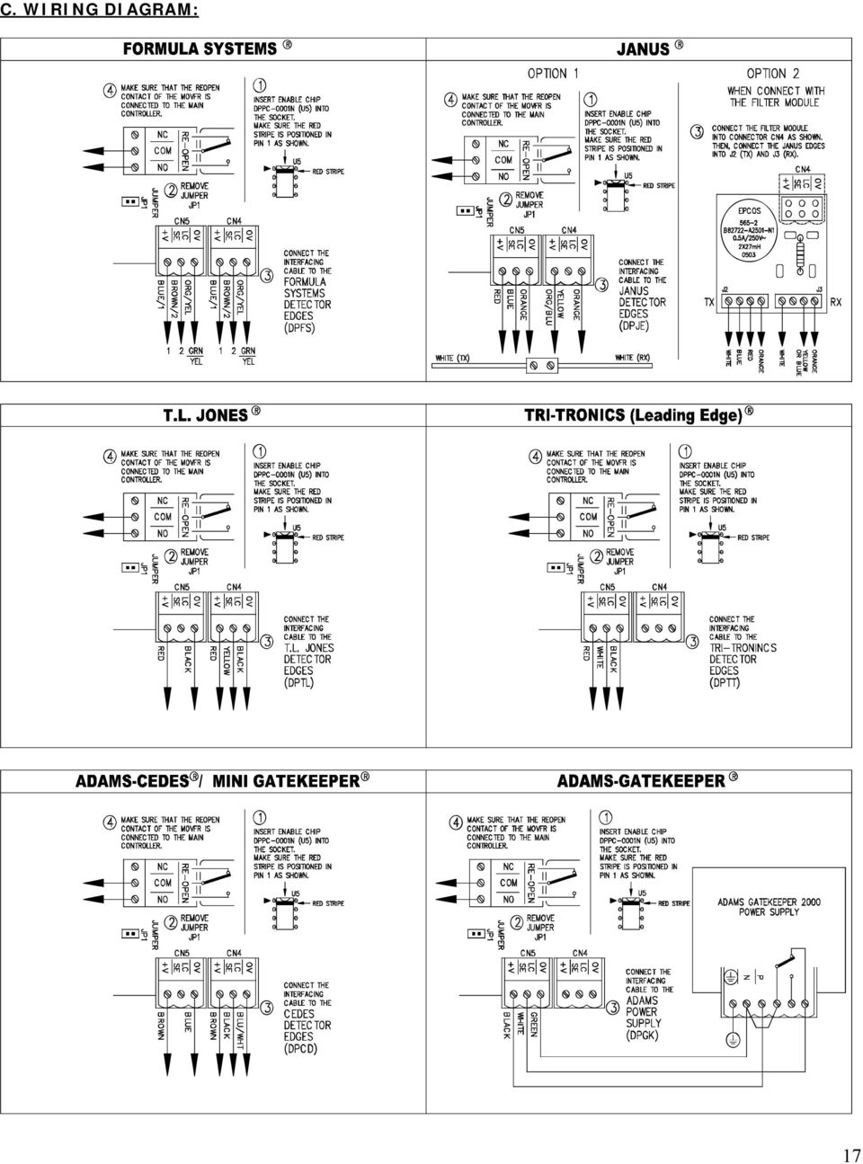
16 7.10 INTERFACING BETWEEN G.A.L. CERTIFIED LIGHT CURTAIN AND THE MOVFR: A. PROCEDURE: To take full advantage of the MOVFR and simplify the REOPENING circuits for the Door Operators, the REOPEN relay in the MOVFR board should be used to Reopen the doors in cases of: Exceeding the Limit of the Torque allowed. Exceeding the Limit of the Speed allowed. Obstructing the Light Curtain. The exceeding Torque and exceeding Speed features have already been built in the MOVFR board. Additionally, for the obstruction of the Infrared Light Curtains, the following illustration shows the interfacing procedure of a G.A.L. Certified Infra-Red Light Curtain and the G.A.L. MOVFR board. 1 st. Plug the Enable Chip into the Socket U5 as shown. Make sure the RED mark is positioned in pin 1 on left as shown. Call G.A.L MFG. CORP. to obtain the Programmable DPPC-0001N Enable Chip. 2 nd. Remove Jumper JP1 3 rd. Plug the Light Curtain Connectors into the mating Connector CN4 & CN5. Note: Connectors CN4 & CN5 are swappable. 4 th. Make sure that the REOPEN Contacts of the MOVFR are Connected to the Main Controller Fo llowings are the G.A.L. CERTIFIED INFRARED LIGHT CURTAIN DETECTORS, in alphabetical order, that are available from G.A.L MFG. CORP. ( Toll Free Phone: (877-GAL-ELEV) B. OPERATION: - Adams - Janus - Formula Systems - TL Jones - Tritronics When obstruction on the Edges occurs, the Reopen LED on the MOVFR will turn on and the Reopen Relay will be activated. The Reopen contacts will send reopen signal to the Main Controller and Wait for the DO (Door Open) Signal from the Main Controller to Reopen the door. 16

17 C. WIRING DIAGRAM: 17
18 18

19 7.12 FAULT DESCRIPTION & FAULT RESET: F01 F02 F03 F04 F07 F13 F14 F33 F100 HW Over Current The AC drive detects an abnormal increase in current. The maximum allowable hardware current is 300% (9A). When the drive output has exceeded this limit, the F01 fault code will display on the Parameter Unit Display. Over Voltage The AC drive detects that the DC bus voltage has exceeded its maximum allowable value, 400V. When the DC bus voltage has exceeded this value, the F02 fault code will display on the Parameter Unit Display. Heatsink OverTmp The AC drive temperature sensor detects excessive heat. When the Heat Sink temperature has exceeded 95 o C, the F03 fault code will display on the Parameter Unit Display. Drive Overload The AC drive detects excessive drive output current. The AC drive can withstand up to 150% of rated current (4.5A) for 1 minute. When this limit has been exceeded, the F04 fault code will display on the Parameter Unit Display. Motor Overload The AC drive detects an excessive motor load. When the value of maximum allowable motor load, which is the setting value of Pr.#99 multiplied by 150% for 1 minute, has been exceeded, the F07 fault code will display on the Parameter Unit Display. Ground Fault The AC drive output is abnormal. When the output terminal is grounded (short circuit current is 50% more than the AC drive rated current), the AC drive power module may be damaged. The short circuit protection is provided for AC drive protection, not user protection. Under Voltage The AC drive detects that the DC bus voltage has fallen below its minimum value, 150VAC. When the input voltage has fallen below this value, the F14 fault code will display on the Parameter Unit Display. Auto Reset Trials When the AC drive auto-reset a fault unsuccessfully, the F33 fault code will display on the Parameter Unit Display. EEPROM failure When the internal memory IC cannot be programmed, the F100 fault code will display on the Parameter Unit Display. NOTE: All the above Faults are re-settable by change the Value of Parameter 110 to 1 and use the following procedure: Set Par. 112 for the Number of Retries. Default Value: 6 Range: 0 9 Increment: 1 After fault occurs, the AC drive can be reset/restarted automatically up to 10 times. Setting this parameter to 0 will disable the reset/restart operation after any fault has occurred. 19

20 Set Par.113 for the Retry Waiting Time. Default Value: 2.5 Range: Sec. Increment: 0.1 Sec. Sets the time between restart attempts when Auto Rstrt Tries is set to a value other than zero. Set Par. 114 for the Retry Selection. Default Value: 1023 Range: Increment: 1 Settings 1: Ground Fault can be auto reset 2: Over Voltage can be auto reset 4: Over Current can be auto reset 8: Low Voltage can be auto reset 16: Motor Over Load can be auto reset 32: Drive Over Temperature can be auto reset 64: Drive Over Load can be auto reset 128: Current sensor Broken can be auto reset 256: EEPROM Broken can be auto reset 512: Software Over Voltage can be auto reset Example: If a "Ground Fault, "Over Current" and "Drive Over Load" needs to be auto reset then Par 114 should be set to 69 (1+4+64). The default value is "1023" which means all faults can be auto reset. Set Par. 115 for Reset Fault Default Value: 0 Range: 0 2 Increment: 1 Settings 0: Idle State 1: Resets the active fault but does not clear any fault buffer 2: Resets the active fault and clears all fault buffers to 0 Resets a fault and clears the fault buffer. Used primarily to clear a fault over network communications. 20

21 7.13 APPLICATIONS FOR THE HEAVY INPUT: The door operator may operate two different hoist-way doors, one door is heavier than the other, in one elevator. As a result, the setting of Torque, and Speed of one door may not be applicable for the other door. More importantly, it may be a code violation issue due to the constraint of the Kinetic energy and the Torque allowance. The HEAVY input will resolve this issue. When the HEAVY input is activated, the Drive will operate with a different set of Parameters for the heavier door. In other circumstance, the door may encounter different pressures from one floor to another. For example, in the subway stations or airports, the door may have a windy condition. With the normal setting, the door may not be able to operate properly. Again, the HEAVY input will help to resolve this issue. In order to gain the access to the HEAVY set of Parameters, change the value of the Parameter 110 from 0 to 1. The HEAVY set of Parameters is located as follows: Pr.11 Heavy Door Close Holding Torque Unit: 0.1 % Default: 3 % Range: 0 ~ 30 % Increase the setting when the motor torque in low speed range is insufficient. Pr.12 Heavy Door Close Holding Speed Default: 2.0 Hz Pr.13 Heavy Door Close Torque (Base Freq.) Default: Hz This parameter is used to adjust the AC drive output (voltage, frequency) to the motor rating. 21
22 Pr.14 Heavy Door High Speed Close (HSC) Default: 19.0 Hz Pr.15 Heavy Final Speed Close (FSC) Default: 5.0 Hz Pr.16 Pr.17 Pr.18 Pr.19 Heavy Door Nudging Speed Default: 9.0 Hz Heavy Door Close Acceleration Time Unit: 0.1 Sec Default: 6.0 Range: 0 ~ Sec The Acceleration Time is used to determine the time required for the AC drive to ramp from 0 Hz to its Reference frequency (Pr.50). Heavy Door Close Deceleration Time Unit: 0.1 Sec Default: 10.0 Range: 0 ~ Sec The Deceleration Time is used to determine the time required for the AC drive to decelerate from the Reference frequency (Pr.50) down to 0 Hz. Heavy Door Stall Reverse Force (output current detection level) Unit: (0.1 %) Default: 1.2A Range: 0 ~ %rated If the output current remains higher than this setting during AC drive operation, the output current detection signal is on from the open collector output terminal of the AC drive. 22
23 Pr.31 Heavy Door Quick Stop on Reverse Unit: 0.1 A Default: 2.0A Range: 0~180 %rated This parameter determines the level of the DC Braking Current output to the motor during stopping. Pr.32 Heavy Door Slow Start Open (SSO) Default: 5.0 Hz Pr.33 Heavy Door High Speed Open (HSO) Default: 45.0 Hz Pr.34 Heavy Door Medium Speed Open (MSO) Default: 20.0 Hz Pr.35 Heavy Door Final Speed Open (FSO) Default: 5.0 Hz Pr.36 Heavy Door Open Acceleration Time Unit: 0.1 Sec Default: 4.0 Sec Range: 0~400.0 Sec The Acceleration Time is used to determine the time required for the AC drive to ramp from 0 Hz to its Reference frequency (Pr.50). Pr.37 Heavy Door Open Deceleration Time Unit: 0.1 Sec Default: 10.0 Sec Range: 0 ~ Sec The Deceleration Time is used to determine the time required for the AC drive to decelerate from the Reference frequency (Pr.50) down to 0 Hz. Pr.38 Heavy Door Open Slow Speed Torque Unit: 0.1 % Default: 0 % Range: 0 ~ 30 % Increase the setting when motor torque in low speed range is insufficient. 23
24 Pr.39 Heavy Door Open Torque (Second V/F (base frequency) Default: 80.0 Hz Range: 0 ~ 400 Hz Increase the setting when motor torque in low speed range is insufficient. Pr.45 Heavy Door DC Injection Brake Operation Frequency Default: 60 Hz This parameter determines the frequency that the DC Braking will begin to output once Frequency is reached during deceleration. Pr.46 Heavy Door DC Injection Brake Operation Time Unit: 0.1 Sec Default: 1.0 Sec Range: 0 ~ 10.0 Sec This parameter determines the duration that the DC Braking current will be applied to the motor during stopping. 24
25 7.14 PARAMETERS LIST: Pr.0 Pr.1 Max. Close Speed (Close Speed detection) Default: 30.0 Hz The output frequency detection signal is on when the output frequency reaches or exceeds the setting value. Close Holding Torque (torque boost) Unit: 0.1 % Default: 3 % Range: 0 ~ 30 % Increase the setting when motor torque in low speed range is insufficient. Pr.2 Pr.3 Pr.4 Pr.5 Pr.6 Close Holding Speed Default: 2.0 Hz Close Torque (Base Freq.) Default: Hz This parameter is used to adjust the AC drive output (voltage, frequency) to the motor rating. High Speed Close (HSC) Default: 19.0 Hz Final Speed Close (FSC) Default: 5.0 Hz Nudging Speed Default: 9.0 Hz 25
26 Pr.7 Pr.8 Pr.9 Close Acceleration Time Unit: 0.1 Sec Default: 6.0 Range: 0 ~ Sec The Acceleration Time is used to determine the time required for the AC drive to ramp from 0 Hz to its Reference frequency (Pr.50). Close Deceleration Time Unit: 0.1 Sec Default: 10.0 Range: 0 ~ Sec The Deceleration Time is used to determine the time required for the AC drive to decelerate from the Reference frequency (Pr.50) down to 0 Hz. Stall Reverse Force (output current detection level) Unit: (0.1 %) Default: 1.2A Range: 0 ~ %rated If the output current remains higher than this setting during AC drive operation, the output current detection signal is on from the open collector output terminal of the AC drive. Pr.11 Heavy Door Close Holding Torque Unit: 0.1 % Default: 3 % Range: 0 ~ 30 % Increase the setting when the motor torque in low speed range is insufficient. Pr.12 Heavy Door Close Holding Speed Default: 2.0 Hz Pr.13 Heavy Door Close Torque (Base Freq.) Default: Hz This parameter is used to adjust the AC drive output (voltage, frequency) to the motor rating. 26
27 Pr.14 Heavy Door High Speed Close (HSC) Default: 19.0 Hz Pr.15 Final Speed Close (FSC) Default: 5.0 Hz Pr.16 Heavy Door Nudging Speed Default: 9.0 Hz Pr.17 Heavy Door Close Acceleration Time Unit: 0.1 Sec Default: 6.0 Range: 0 ~ Sec The Acceleration Time is used to determine the time required for the AC drive to ramp from 0 Hz to its Reference frequency (Pr.50). Pr.18 Heavy Door Close Deceleration Time Unit: 0.1 Sec Default: 10.0 Range: 0 ~ Sec The Deceleration Time is used to determine the time required for the AC drive to decelerate from the Reference frequency (Pr.50) down to 0 Hz. Pr.19 Heavy Door Stall Reverse Force (output current detection level) Unit: (0.1 %) Default: 1.2A Range: 0 ~ %rated If the output current remains higher than this setting during AC drive operation, the output current detection signal is on from the open collector output terminal of the AC drive. 27
28 Pr.20 Open Speed detection Default: 30.0 Hz The output frequency detection signal is on when the output frequency reaches or exceeds the setting value. Pr.21 Quick Stop on Reverse Unit: 0.1 A Default: 2.0A Range: 0~180 %rated This parameter determines the level of the DC Braking Current output to the motor during stopping. Pr.22 Slow Start Open (SSO) Default: 5.0 Hz Pr.23 High Speed Open (HSO) Default: 45.0 Hz Pr.24 Medium Speed Open (MSO) Default: 20.0 Hz Pr.25 Final Speed Open (FSO) Default: 5.0 Hz Pr.26 Open Acceleration Time Unit: 0.1 Sec Default: 4.0 Sec Range: 0~400.0 Sec The Acceleration Time is used to determine the time required for the AC drive to ramp from 0 Hz to its Reference frequency (Pr.50). Pr.27 Open Deceleration Time Unit: 0.1 Sec Default: 10.0 Sec Range: 0 ~ Sec The Deceleration Time is used to determine the time required for the AC drive to decelerate from the Reference frequency (Pr.50) down to 0 Hz. Pr.28 Open Slow Speed Torque Unit: 0.1 % Default: 0 % Range: 0 ~ 30 % Increase the setting when motor torque in low speed range is insufficient. 28
29 Pr.29 Open Torque (Second V/F (base frequency) Default: 80.0 Hz Range: 0 ~ 400 Hz Increase the setting when motor torque in low speed range is insufficient. Pr.31 Heavy Door Quick Stop on Reverse Unit: 0.1 A Default: 2.0A Range: 0~180 %rated This parameter determines the level of the DC Braking Current output to the motor during stopping. Pr.32 Heavy Door Slow Start Open (SSO) Default: 5.0 Hz Pr.33 Heavy Door High Speed Open (HSO) Default: 45.0 Hz Pr.34 Heavy Door Medium Speed Open (MSO) Default: 20.0 Hz Pr.35 Heavy Door Final Speed Open (FSO) Default: 5.0 Hz Pr.36 Heavy Door Open Acceleration Time Unit: 0.1 Sec Default: 4.0 Sec Range: 0~400.0 Sec The Acceleration Time is used to determine the time required for the AC drive to ramp from 0 Hz to its Reference frequency (Pr.50). 29
30 Pr.37 Heavy Door Open Deceleration Time Unit: 0.1 Sec Default: 10.0 Sec Range: 0 ~ Sec The Deceleration Time is used to determine the time required for the AC drive to decelerate from the Reference frequency (Pr.50) down to 0 Hz. Pr.38 Heavy Door Open Slow Speed Torque Unit: 0.1 % Default: 0 % Range: 0 ~ 30 % Increase the setting when motor torque in low speed range is insufficient. Pr.39 Heavy Door Open Torque (Second V/F (base frequency) Default: 80.0 Hz Range: 0 ~ 400 Hz Increase the setting when motor torque in low speed range is insufficient. 30
31 Pr.40 DC Injection Brake Operation Frequency Default: 60 Hz This parameter determines the frequency that the DC Braking will begin to output once Frequency is reached during deceleration. Pr.41 DC Injection Brake Operation Time Unit: 0.1 Sec Default: 1.0 Sec Range: 0 ~ 10.0 Sec This parameter determines the duration that the DC Braking current will be applied to the motor during stopping. Pr.45 Heavy Door DC Injection Brake Operation Frequency Default: 60 Hz This parameter determines the frequency that the DC Braking will begin to output once Frequency is reached during deceleration. Pr.46 Heavy Door DC Injection Brake Operation Time Unit: 0.1 Sec Default: 1.0 Sec Range: 0 ~ 10.0 Sec This parameter determines the duration that the DC Braking current will be applied to the motor during stopping. 31
32 Pr.51 Max. Carrier Frequency Carrier frequency for the PWM output waveform Unit: 0.1k Hz Default: 11.0k Hz Range: 2.0 ~ 15.0kHz This parameter determines the maximum carrier frequency of the AC drive. Carrier Frequency Acoustic Noise Electromagnetic Noise, Leakage Current Heat Dissipation 2kHz Significant Minimal Minimal 15KHz Minimal Significant Significant From the table, the PWM carrier frequency has a significant influence on the electromagnetic noise, heat dissipation of the AC drive, and the acoustic noise to the motor. Pr.67 Door Zone Functionality Unit: 1 Default: 0 Range: 0 ~ 1 0: Disable Door Zone Functionality 1: Enable Door Zone Functionality Pr.99 Motor Over Load Current Unit: 0.1 A Default: 2.5 A Range: 0 ~ 6 A The setting is proportional to the rated current of motor. Pr.110 User Group Read Selection Unit: 1 Default: 0 Range: 0 ~ 9999 When the setting value is 1, user can view and select parameters Pr.0~46, 51, 67, 99, 110 and 112~115. If the setting value is set to any other value (not 1), user can view and select parameters Pr.0~9, 20~29, 51 and 110 only. Pr.112 Number of Retries Unit: 1 Default: 6 Range: 0 ~ 9 After a fault occurs, the AC drive can be reset/restarted automatically up to 10 times. Setting this parameter to 0 will disable the reset/restart operation after any fault has occurred. Pr.113 Retry Waiting Time Unit: 0.1 Sec Default: 2.5 Sec Range: 0 ~ Sec Sets the time between restart attempts when Auto Restart Tries is set to a value other than zero. 32
33 Pr.114 Retry Selection Unit: 1 Default: 1023 Range: 0 ~ : Ground Fault can be auto reset 2: Over Voltage can be auto reset 4: Over Current can be auto reset 8: Low Voltage can be auto reset 16: Motor Over Load can be auto reset 32: Drive Over Temperature can be auto reset 64: Drive Over Load can be auto reset 128: Current sensor Broken can be auto reset 256: EEPROM Broken can be auto reset 512: Software Over Voltage can be auto reset If a "Ground Fault, "Over Current" and "Drive Over Load" needs to be auto reset then Par 114 should be set to 69 (1+4+64). The default value is "1023" which means all faults can be auto reset. Pr.115 Reset Fault Unit: 1 Default: 0 Range: 0 ~ 2 0: Idle State 1: Resets the active fault but does not clear any fault buffer 2: Resets the active fault and clears all fault buffers to 0 Resets a fault and clears the fault buffer. Used primarily to clear a fault over network communications. 33
34 7.15 HOW TO REPLACE THE DRIVE: 1. Disconnect the door operator power from the machine room 2. Flip ON-OFF switch on operator board to OFF position and the AUTO-MAN switch to the MAN position. Wait 10 minutes for the drive s internal capacitor to completely discharge. 3. Unplug the ribbon cable from the drive. 4. Unplug the green power connector. 5. Remove drive mounting screws. 6. Install the new drive 7. Plug the green power connector 8. Plug the ribbon cable to the drive 9. Reapply power to the drive but leave the switch in the MAN position for now. 10. WRITE the parameters from the parameter unit into the drive as explained in section Check door operation with the OPEN-CLOSE switch before returning the system to AUTO. Copyright 2004, G.A.L. Manufacturing Corporation All rights reserved. No part of this document may be reproduced in any form, machine or natural, without the express written consent of G.A.L Manufacturing Corporation. 34
MOVFR DOOR OPERATOR INSTALLATION AND ADJUSTING MANUAL
 G.A.L. Manufacturing Corporation 50 East 153rd Street, Phone 718-292-9000 Fax 718-292-2034 Bronx, N.Y. 10451 Toll Free 877-425-3538 Web www.gal.com 877-425-7763 E-mail info@gal.com MOVFR DOOR OPERATOR
A1000 Cheat Sheet (Open Loop Vector)
") A1000 Cheat Sheet (Open Loop Vector) The following procedure is a supplement to supplied with this equipment and will guide the user in properly wiring the A1000 and. It will also show the user how to
A1000 Cheat Sheet (Open Loop Vector) The following procedure is a supplement to supplied with this equipment and will guide the user in properly wiring the A1000 and. It will also show the user how to
CHAPTER 11: Flip Flops
 CHAPTER 11: Flip Flops In this chapter, you will be building the part of the circuit that controls the command sequencing. The required circuit must operate the counter and the memory chip. When the teach
NX Series Inverters. HVAC Pocket Programming Guide
 NX Series Inverters HVAC Pocket Programming Guide HVAC Pocket Programming Guide HVAC Pocket Programming Guide / Contents This guide provides a single reference document for the user of NXL HVAC (product
GPD 506/P5 Start-up Procedure and Checklist
 GPD 506/P5 Start-up Procedure and Checklist Preparation for GPD506/P5 Drive Start-Up...2 HVAC Start-Up Procedure for GPD 506/P5 WITH Bypass Option:...4 HVAC Start-Up Procedure for GPD 506/P5 WITHOUT Bypass
Mini Breakout-Board. CNC Interface for LPT Port. Installation Manual Version 4
 Mini CNC Interface for LPT Port Version 4 Product Brief This breakout-board is designed to connect up to four stepper or servo drives to the parallel port of a PC. This requires the use of a CNC controller
AC-115 Compact Networked Single Door Controller. Installation and User Manual
 AC-115 Compact Networked Single Controller Installation and User Manual December 2007 Table of Contents Table of Contents 1. Introduction...5 1.1 Key Features... 6 1.2 Technical Specifications... 7 2.
What Is Regeneration?
 What Is Regeneration? Braking / Regeneration Manual Regeneration Overview Revision 1.0 When the rotor of an induction motor turns slower than the speed set by the applied frequency, the motor is transforming
DMX-K-DRV. Integrated Step Motor Driver + (Basic Controller) Manual
 Manual") DMX-K-DRV Integrated Step Motor Driver + (Basic Controller) Manual DMX-K-DRV Manual page 1 rev 1.33 COPYRIGHT 2007 ARCUS, ALL RIGHTS RESERVED First edition, June 2007 ARCUS TECHNOLOGY copyrights this document.
DMX-K-DRV Integrated Step Motor Driver + (Basic Controller) Manual DMX-K-DRV Manual page 1 rev 1.33 COPYRIGHT 2007 ARCUS, ALL RIGHTS RESERVED First edition, June 2007 ARCUS TECHNOLOGY copyrights this document.
USER MANUAL CHARGING STATIONS FOR ELECTRIC VEHICLES
 USER MANUAL CHARGING STATIONS FOR ELECTRIC VEHICLES 204.CAxxx 204.CBxxx 204.UBxxx 204.WBxxx MP36289 1 ZP90856-GB-6 INDICE 1 SYSTEM DESCRIPTION... 4 1.1 MODES OF OPERATION... 4 2 USER INTERFACE... 6 2.1
LIFT CONTROL SYSTEMS CATALOGUE 2007
 LIFT CONTROL SYSTEMS CATALOGUE 2007 All Your Needs For Elevators INDEX 1. Lift Control Cards... 3 2. Speed Control Units... 7 3. Emergency Rescue Cards... 8 4. Lift Control Panels... 10 5. Photocells...
MODEL 5010 DUAL CHANNEL SMOKE/FIRE DETECTION MODULE
 DESCRIPTION MODEL 5010 DUAL CHANNEL SMOKE/FIRE DETECTION MODULE DESCRIPTION The SST Model 5010 Two Channel Smoke/Fire Detection Module provides two independent detection input channels for the NOVA-5000
UM-X Field display for continous level sensors
 Technical Documentation Field display for continous level sensors 10/2007 Edition: 1 Item No.: 207120 FAFNIR GmbH Bahrenfelder Str. 19 D-22765 Hamburg Telephone: +49 (0)40-39 82 07-0 Fax: +49 (0)40-3 90
Operational Overview and Controls Guide. Two or Three Pump IronHeart Lite with Variable Frequency Drives
 DOCUMENT: ECSEQ6-0 EFFECTIVE: 09/23/10 SUPERSEDES: Operational Overview and Controls Guide Two or Three Pump IronHeart Lite with Variable Frequency Drives 6700 Best Friend Road. Norcross, GA 30071. (770)
Electronic Power Control
 Service. Self-Study Programme 210 Electronic Power Control Design and Function With the Electronic Power Control system, the throttle valve is actuated only by an electric motor. This eliminates the need
Daker DK 1, 2, 3 kva. Manuel d installation Installation manual. Part. LE05334AC-07/13-01 GF
 Daker DK 1, 2, 3 kva Manuel d installation Installation manual Part. LE05334AC-07/13-01 GF Daker DK 1, 2, 3 kva Index 1 Introduction 24 2 Conditions of use 24 3 LCD Panel 25 4 Installation 28 5 UPS communicator
..OR How To Protect your 3-Phase Equipment Investment with 3-Phase Monitors from Time Mark...
 ..OR How To Protect your 3-Phase Equipment Investment with 3-Phase Monitors from Time Mark... TIME MARK CORPORATION 11440 EAST PINE STREET TULSA, OK 74116 USA tel 918 438-1220 fax 918 437-7584 www.time-mark.com
TAKEDO -3VF V20 INSTRUCTION MANUAL. www.sms.bo.it 3 18-10-2013. REL. DATE T.M. Check and Approval
 TAKEDO -3VF V20 INSTRUCTION MANUAL 3 18-10-2013 REL. DATE T.M. Check and Approval www.sms.bo.it PAGE INTENTIONALLY LEFT BLANK 1 INTRODUCTION TAKEDO-3VF V20 is a new type of drive with built-in EMC filter,
DC-8706K Auto Dial Alarm System
 DC-8706K Auto Dial Alarm System User Guide Basic Contents: 1x the host unit; 1x wireless door (window) magnet; 1x wireless infrared detector; 2x remote control; 1x siren; 1x phone core; 1x AC to DC power
FlexPak 3000 Digital DC Drive Software Reference Manual Version 4.3
 FlexPak 3000 Digital DC Drive Software Reference Manual Version 4.3 Instruction Manual D2-3405-2 The information in this manual is subject to change without notice. Throughout this manual, the following
Servo Motors (SensorDAQ only) Evaluation copy. Vernier Digital Control Unit (DCU) LabQuest or LabPro power supply
 Evaluation copy. Vernier Digital Control Unit (DCU) LabQuest or LabPro power supply") Servo Motors (SensorDAQ only) Project 7 Servos are small, relatively inexpensive motors known for their ability to provide a large torque or turning force. They draw current proportional to the mechanical
Servo Motors (SensorDAQ only) Project 7 Servos are small, relatively inexpensive motors known for their ability to provide a large torque or turning force. They draw current proportional to the mechanical
INSTALLATION/PROGRAMMING INSTRUCTIONS E4KP ENTRYCHECK
 Security Door Controls 3580 Willow Lane, Westlake Village, CA 91361-4921 (805) 494-0622 Fax: (805) 494-8861 www.sdcsecurity.com E-mail: service@sdcsecurity.com INSTALLATION/PROGRAMMING INSTRUCTIONS E4KP
JNIOR. Overview. Get Connected. Get Results. JNIOR Model 310. JNIOR Model 312. JNIOR Model 314. JNIOR Model 410
 The INTEG is an Ethernet I/O (digital, analog) device that monitors and controls a small set of process signals. functions as both basic I/O for integration with another application or system AND as a
LIFT CONTROL SYSTEMS CATALOGUE 2007
 LIFT CONTROL SYSTEMS CATALOGUE 2007 All Your Needs For Elevators INDEX 1. Lift Control Cards... 3 2. Speed Control Units... 7 3. Emergency Rescue Cards... 8 4. Lift Control Panels... 10 5. Photocells...
LG Air Conditioning Multi F(DX) Fault Codes Sheet. Multi Split Units
 Fault Codes Sheet. Multi Split Units") Multi Split Units If there is a fault on any LG Multi unit, an Error mark is indicated on the display window of the indoor unit, wired-remote controller, and LED s of outdoor unit control board. A two
Multi Split Units If there is a fault on any LG Multi unit, an Error mark is indicated on the display window of the indoor unit, wired-remote controller, and LED s of outdoor unit control board. A two
DORMA MODEL PS-406BB POWER SUPPLY INSTALLATION INSTRUCTIONS
 Features: INSTALLATION Install in accordance with NFPA 70. DORMA MODEL PS-406BB POWER SUPPLY INSTALLATION INSTRUCTIONS Up to 1.95 Amps Load Capacity Class 2 Rated Outputs Overload, Over Voltage, and Short
CAUTION! THE 7I29 USES VOLTAGE AND POWER LEVELS THAT REPRESENT A HAZARD TO LIFE AND LIMB.
 7I29 MANUAL Rev 1.5 CAUTION! THE 7I29 USES VOLTAGE AND POWER LEVELS THAT REPRESENT A HAZARD TO LIFE AND LIMB. THE 7I29 IS INTENDED FOR USE BY OEMS THAT WILL INTEGRATE IT INTO A SYSTEM WITH INTERLOCKS AND
TS510 & TS500. Installation & User Guide. Compatible Equipment
 Installation & User Guide Compatible Equipment TS510 REM - Remote Keypad 9040 - Loudspeaker DC54/58 - Digital Communicator SD1+ - Speech Dialler 496525 Issue A 1 of 10 TS510 and TS500 Overview Introduction
Speed Control Methods of Various Types of Speed Control Motors. Kazuya SHIRAHATA
 Speed Control Methods of Various Types of Speed Control Motors Kazuya SHIRAHATA Oriental Motor Co., Ltd. offers a wide variety of speed control motors. Our speed control motor packages include the motor,
SECTION 13850 DETECTION AND ALARM
 SECTION 13850 DETECTION AND ALARM PART 1 GENERAL 1.01 SUMMARY A. Section Includes 1. Control Panel 2 Associated Equipment B. Products Installed But Not Supplied Under This Section 1. Section 16140 - Wiring
Dyeing Programmer DP - 01
 Dyeing Programmer DP - 01 Display and Controls. 1) Display: 16/2 alphanumeric display 2) Temperature range: 0 to 150 degree. 3) Resolution: 1 degree. 4) Accuracy: +/- 1 degree. 5) Temperature control setting:
DC Motor control Reversing
 January 2013 DC Motor control Reversing and a "Rotor" which is the rotating part. Basically there are three types of DC Motor available: - Brushed Motor - Brushless Motor - Stepper Motor DC motors Electrical
3FBD DC Motor Drive User Manual
 3FBD DC Motor Drive User Manual Via I. Alpi 6 - zona industriale - Lonato (BS) Tel. +39 30 9913491 r.a. Fax. +39 30 9913504 http://www.re-elettronica.it info@re-elettronica.it Pag. 1 Index Index... pag.1
Product Description Full Voltage Starting Electric Fire Pump Controllers FTA1000
 Product Description Full Voltage Starting Electric Fire Pump Controllers FTA1000 Description Firetrol FTA1000 Full Voltage Fire Pump Controllers are intended for use with electric motor driven fi re pumps
TOSVERT VF-MB1. Functions for lift application
 TOSVERT VF-MB1 Functions for lift application The technical information in this manual is provided to explain the principal functions and applications of the product, but not to grant you a license to
Multi-Protocol decoder 76 200 with Load regulation
 Multi-Protocol decoder 76 2 with Load regulation For locomotives with universal motors on digital layouts operating in the DCC and Motorola data format. Features 76 2 Load regulated multi-protocol decoder
Match. GE Digital Energy. Uninterruptible Power Supply 500-1500 VA. Technology for the Digital World. Match UPS. GE Digital Energy.
 Match Uninterruptible Power Supply 500-1500 VA Manufactured by: General Electric Company Telephone +41 (0)91 / 850 51 51 CH 6595 Riazzino (Locarno) Fax +41 (0)91 / 850 51 44 Switzerland Website www.gedigitalenergy.com
Configure Inverter output for two utility settings, (1)120V/60Hz, (2)220V/50Hz
120V/60Hz, (2)220V/50Hz") HV Solar Inverter System GUI Overview January 2012 TMS320C2000 Systems Applications Collateral The HV Solar Inverter System GUI provides a simple interface to evaluate some of the functionalities of the
HV Solar Inverter System GUI Overview January 2012 TMS320C2000 Systems Applications Collateral The HV Solar Inverter System GUI provides a simple interface to evaluate some of the functionalities of the
Speed Control Relays SX2
 SX2 File 850 CONENS Description.....................................................Page General Information................................................ 2-3 SX2DV General Information...........................................
NELSON VOLTAGE MONITOR INSTALLATION & PROGRAMMING MANUAL
 NELSON VOLTAGE MONITOR INSTALLATION & PROGRAMMING MANUAL CONTENTS GENERAL INFORMATION...3 INSTALLATION...3 FIELD WIRING...4 PROGRAMMING...4 Circuit Monitor Options...5 Power Frequency...5 Alarm Silence
Series 427. 1/16 DIN Multi-Mode Bar Graph Display Timer TIMERS PRODUCT HIGHLIGHTS
 Series 427 1/16 DIN Multi-Mode Bar Graph Display Timer PRODUCT HIGHLIGHTS Digital Setting with 0.1% Accuracy Unique LED Bargraph Indicates Time Cycle in 20% Increments 8 Field Selectable Modes of Operation
Allen-Bradley/Rockwell
 MANUFACTURER DATA SHEET High Speed Counter Manufacturer: Allen-radley/Rockwell Model Number: 1746-HSCE See www.geomartin.com for additional PDF datasheets Martin Part Number: E-014901-03 VendorPartNumber:
543-0032-00, 943-0032-00. User s Manual
 543-0032-00, 943-0032-00 User s Manual 1 Comfort Alert Diagnostics Faster Service And Improved Accuracy The Comfort Alert diagnostics module is a breakthrough innovation for troubleshooting heat pump and
EET272 Worksheet Week 9
 EET272 Worksheet Week 9 answer questions 1-5 in preparation for discussion for the quiz on Monday. Finish the rest of the questions for discussion in class on Wednesday. Question 1 Questions AC s are becoming
AUTOMATIC TRANSFER SWITCH CONTROL UNIT OPERATOR S MANUAL
 ATS-220 AUTOMATIC TRANSFER SWITCH CONTROL UNIT OPERATOR S MANUAL For Use in 208 to 240 Volts Single and 3 Phase ATS Systems With 110Volt AC or DC Control Motors and selenoids 4501 NW 27 ave Miami FL 33142
Talon and Talon SR User Manual
 Talon and Talon SR User Manual Brushed DC motor controller Version 1.3 Cross the Road Electronics, LLC www.crosstheroadelectronics.com Cross The Road Electronics, LLC Page 1 4/2/2013 Device Overview Clear,
*.ppt 11/2/2009 12:48 PM 1
 Digital Compressor Controller *.ppt 11/2/2009 12:48 PM 1 Copeland Scroll Digital Controller Simple Controller That Enables OEM s To Use Digital Scrolls Relieves OEM From Developing Special Controllers
LG Air Conditioning - Universal Split Fault Codes Sheet. Universal Split Systems
 Universal Split Systems If there is a fault on any LG Universal unit, a two digit number will appear on the remote controllers led display. If the unit does not have a remote controller the fault will
Brake module AX5021. Documentation. Please read this document carefully before installing and commissioning the brake module!
 Documentation Brake module AX5021 Please read this document carefully before installing and commissioning the brake module! Version : 1.2 : 2012.03.05 Date Article-no. : TDmlAX-5021-0000-0200 Page 2/8
ALARM ANNUNCIATOR ME - 3010 INSTRUCTION MANUAL
 ALARM ANNUNCIATOR ME - 3010 INSTRUCTION MANUAL INTRODUCTION... 2.. TECHNICAL DATA... 3 ACCESSORIES... 5. INSTALLATION... 7 OPERATION... 12. TECHNICAL INFORMATION... 13 MAINTENANCE... 14. CONFIGURATIONS...
Figure 1 - Crydom 3RHP Three-phase Hybrid Solid State Contactor. Crydom Inc.
 Crydom RHP Series 3 Phase Hybrid Solid State Contactor By Paul Bachman Fellow Engineer, Crydom, Inc. ABSTRACT Solid State Relays and Contactors (SSRs) have been available in one form or the other for over
IDS X-Series User Manual 700-398-01D Issued July 2012
 1 2 Contents 1. Introduction to the IDS X-Series Panels... 7 2. Before Operating Your Alarm System... 7 3. Understanding the Keypad LEDs... 8 3.1 Viewing Data on an LED Keypad... 12 3.1.1 LED Status Indicators...
WE-350 Series ¼ Turn Electric Actuator
 WE-350 Series ¼ Turn Electric Actuator Operation and Installation Manual Pg 1 (Rev. 020113) Table of Contents 1.0 General 1.1 Pre-Installation Inspection 1.2 Storage 1.3 Features & General Information
Option field bus: without bus with profibus DP. Design-Index (Subject to change)
") Amplifier / controller cards ED1 Digital amplifier / controller card ED1 for 1 or 2 proportional solenoids 4 analogue inputs, of which 2 for differential inputs 8 digital inputs Card setting via PC, multi-function
Amplifier / controller cards ED1 Digital amplifier / controller card ED1 for 1 or 2 proportional solenoids 4 analogue inputs, of which 2 for differential inputs 8 digital inputs Card setting via PC, multi-function
ABB i-bus EIB Shutter Actuators JA/S 2.230.1, JA/S 4.230.1, JA/S 8.230.1, JA/S 4.230.1M, JA/S 8.230.1M, JA/S 4.24.1
 Product Manual ABB i-bus EIB Shutter Actuators JA/S 2.230.1, JA/S 4.230.1, JA/S 8.230.1, JA/S 4.230.1M, JA/S 8.230.1M, JA/S 4.24.1 Intelligent Installation Systems Contents Page 1 Introduction.......................................
IQAN MDM Operation Manual
 IQAN MDM Operation Manual Purpose The primary purpose of this document is to inform a user of the IQAN system on the ease of adjustments of the system. A person can create a much smoother machine control
Analog Servo Drive 25A8
 Description Power Range NOTE: This product has been replaced by the AxCent family of servo drives. Please visit our website at www.a-m-c.com or contact us for replacement model information and retrofit
SERVICE INSTRUCTION R410A. WALL MOUNTEDtype INVERTER SPLIT TYPE ROOM AIR CONDITIONER. Models Indoor unit Outdoor unit
 SERVICE INSTRUCTION SPLIT TYPE ROOM AIR CONDITIONER WALL MOUNTEDtype INVERTER Models Indoor unit Outdoor unit ASYG07LECA ASYG09LECA ASYG12LECA ASYG14LECA AOYG07LEC AOYG09LEC AOYG12LEC AOYG14LEC R410A CONTENTS
Fire Alarm Control Panel. Family. Operating Manual
 Fire Alarm Control Panel Family Operating Manual CONTENTS System Description AH-03312 System Characteristics... Fire Signal Receiving Board Description-4L... Fire Signal Receiving Board Description-8L...
SMART SENSOR COLLECTION
 TEMPERATURE SENSOR This sensor measures temperature in degrees Celsius or Fahrenheit. It works with all SensorHawk base units (SensorHawk-2, SensorHawk-8 and SensorHawk8/20) as well as the SecurityHawk-8
Drives 101. Functions of an Adjustable Frequency Drive (AFD) This lesson covers the basic functions of an Adjustable Frequency Drives (AFD).
 This lesson covers the basic functions of an Adjustable Frequency Drives (AFD).") Drives 101 Lesson 1 Functions of an Adjustable Frequency Drive (AFD) This lesson covers the basic functions of an Adjustable Frequency Drives (AFD). Outline: 3-phase AC Motor 1. Bi-Directional Operation
Drives 101 Lesson 1 Functions of an Adjustable Frequency Drive (AFD) This lesson covers the basic functions of an Adjustable Frequency Drives (AFD). Outline: 3-phase AC Motor 1. Bi-Directional Operation
Antec TruePower User's Manual
 User s Manual Antec TruePower User's Manual Antec TruePower ATX12V power supply Models: TRUE330, TRUE380, TRUE430, TRUE480, TRUE550 Antec Low Noise Technology: The Antec TruePower power supply is equipped
ABB Drives. User s Manual HTL Encoder Interface FEN-31
 ABB Drives User s Manual HTL Encoder Interface FEN-31 HTL Encoder Interface FEN-31 User s Manual 3AUA0000031044 Rev B EN EFFECTIVE: 2010-04-06 2010 ABB Oy. All Rights Reserved. 5 Safety instructions
Inwall 4 Input / 4 Output Module
 Inwall 4 Input / 4 Output Module IO44C02KNX Product Handbook Product: Inwall 4 Input / 4 Output Module Order Code: IO44C02KNX 1/27 INDEX 1. General Introduction... 3 2. Technical data... 3 2.1 Wiring Diagram...
Manual for Fire Suppression & Methane Detection System
 Manual for Fire Suppression & Methane Detection System Fogmaker North America Post address: 150 Gordon Dr Exton, PA 19341 Delivery address: 150 Gordon Dr Exton, PA 19341 Tel: 610-265-3610 Fax: 610-265-8327
NC-12 Modbus Application
 NC-12 Modbus Application NC-12 1 Table of Contents 1 Table of Contents... 2 2 Glossary... 3 SCADA...3 3 NC-12 Modbus in general... 3 4 Entire system... 4 4.1 PFC to PC connection alternatives...4 4.1.1
Theory of Operation. Figure 1 illustrates a fan motor circuit used in an automobile application. The TPIC2101. 27.4 kω AREF.
 In many applications, a key design goal is to minimize variations in power delivered to a load as the supply voltage varies. This application brief describes a simple DC brush motor control circuit using
AuCom s IMS2 soft starters are a total motor starting solution, combining highlevel functionality with ease of use:
 AuCom s IMS2 soft starters are a total motor starting solution, combining highlevel functionality with ease of use: advanced soft start and soft stop control protection functions that operate even when
VLT 6000 HVAC. Contents
 Contents Introduction Safety...3 Safety Guidelines...3 Warnings Against Unintended Start...3 Introduction...4 About this manual...4 Assumptions...4 References...4 Trademarks...5 Programming the VLT 6000
LS1024B / LS2024B/ LS3024B. Solar Charge Controller USER MANUAL
 EPSOLAR LS1024B / LS2024B/ LS3024B Solar Charge Controller USER MANUAL Thank you very much for selecting our product! This manual offers important information and suggestions with respect to installation,
ACS800. Master/Follower Application Guide Supplement to Firmware Manual for ACS800 Standard Application Program
 ACS800 Master/Follower Application Guide Supplement to Firmware Manual for ACS800 Standard Application Program Master/Follower Application Guide Supplement to Firmware Manual ACS800 Standard Application
MANAGEMENT SOLUTION (P.A.M.S.)
") DOORKING SYSTEMS ACCESS CONTROL SOLUTIONS PERIMETER ACCESS MANAGEMENT SOLUTION (P.A.M.S.) Revision N, updated 01.12 PERIMETER ACCESS MANAGEMENT SOLUTION (P.A.M.S.) Design Concept How the System Works TYPICAL
DOORKING SYSTEMS ACCESS CONTROL SOLUTIONS PERIMETER ACCESS MANAGEMENT SOLUTION (P.A.M.S.) Revision N, updated 01.12 PERIMETER ACCESS MANAGEMENT SOLUTION (P.A.M.S.) Design Concept How the System Works TYPICAL
1000W Single Output Power Supply 15V 24V. Protection type: Total Power limit, Latch-style (Recovery after reset AC power ON or inhibit)
") 000W Single Output Power Supply AK-000 series Features: Universal AC input / Full range Programmable output Voltage (0% ~ 05%) Programmable output Current (% ~ 05%) + / 0.5A auxiliary output U profile,
000W Single Output Power Supply AK-000 series Features: Universal AC input / Full range Programmable output Voltage (0% ~ 05%) Programmable output Current (% ~ 05%) + / 0.5A auxiliary output U profile,
ETC TWO STAGE ELECTRONIC TEMPERATURE CONTROL
 RANCO INSTALLATION INSTRUCTIONS ETC TWO STAGE ELECTRONIC TEMPERATURE CONTROL Relay Electrical Ratings PRODUCT DESCRIPTION The Ranco ETC is a microprocessor-based family of electronic temperature controls,
GSM ALARM SYSTEM USER MANUAL
 GSM ALARM SYSTEM USER MANUAL 1. Instruction The alarm system is based on GSM network. With a GSM SIM card, it can be used wherever you want and no need to connect any wire, which is convenient and easy
DK40 Datasheet & Hardware manual Version 2
 DK40 Datasheet & Hardware manual Version 2 IPC@CHIP DK40 Evaluation module Beck IPC GmbH http://www.bcl.de page 1 of 11 Table of contents Table of contents... 2 Basic description... 3 Characteristics...
1R / 4-BUTTON SERIES
 Button 1 1R / 4-BUTTON SERIES VEHICLE SECURITY SYSTEM Standard Features: Two 4-Button Remote Transmitters Status indicator (LED) Valet / override switch Multi-tone siren Dual stage impact detector Remote
conventional system operation
 conventional system operation detection line operation Conventional detection systems normally operate on a 24VDC line. In the standby condition, the detectors will draw a low current, typically less than
650W Single Output Power Supply
 AK-650 series Features : Universal AC input with active PFC Programmable output Voltage ( 0% ~ 05% ) Programmable output Current ( % ~ 05% ) High efficiency up to 9% + / 0.5A auxiliary output Intelligent
Automation System TROVIS 6400 TROVIS 6493 Compact Controller
 Automation System TROVIS 6400 TROVIS 6493 Compact Controller For panel mounting (front frame 48 x 96 mm/1.89 x 3.78 inch) Application Digital controller to automate industrial and process plants for general
RISH EM 3490 DS Dual Source Energy Meter RISH EM 3490 DS. Application : Product Features:
 Application : RISH Master 3490 DS measures important electrical parameters of Utility (in normal mode) & Generators (in Power back up) in three phase and single phase Network & replaces the multiple analog
Shutter Actuator Standard, 4-fold, 230 VAC, MDRC RA/S 4.230.1, GH Q631 0076 R0111. ABB i-bus EIB
 , GH Q631 0076 R0111 2CDC 071 240 F0003 The Shutter Actuator Standard is used to control a maximum of four independent 230 VAC drives for positioning shutters, blinds, awnings and other hangings as well
EDI Distributor Control Interface Wiring and Setup Instructions
 Universal I/O EDI Distributor Control Interface Wiring and Setup Instructions EDI UNIVERSAL I/O INTERFACE MODULE The only interface needed for EDI-V5 controls Network compatible with all older EDI controls
CONSTRUCTION STANDARDS DIVISION 23 HEATING VENTILATING AND AIR CONDITIONING
 PART 1-GENERAL 1.01 DESCRIPTION A. This specification is to cover a complete Variable Frequency motor Drive (VFD) consisting of a pulse width modulated (PWM) inverter designed for use on a standard NEMA
SYSTEM 45. C R H Electronics Design
 SYSTEM 45 C R H Electronics Design SYSTEM 45 All in one modular 4 axis CNC drive board By C R Harding Specifications Main PCB & Input PCB Available with up to 4 Axis X, Y, Z, & A outputs. Independent 25
PAC1 Door Access Controller
 PAC1 Door Access Controller Series 2 IMPORTANT DIFFERENCES FROM SERIES 1 1. A PACDL data logger revision 4.0 or higher attached to the DLOG terminal is able to program all features (i.e. times, relay type,
Current Loop Tuning Procedure. Servo Drive Current Loop Tuning Procedure (intended for Analog input PWM output servo drives) General Procedure AN-015
 General Procedure AN-015") Servo Drive Current Loop Tuning Procedure (intended for Analog input PWM output servo drives) The standard tuning values used in ADVANCED Motion Controls drives are conservative and work well in over 90%
Servo Drive Current Loop Tuning Procedure (intended for Analog input PWM output servo drives) The standard tuning values used in ADVANCED Motion Controls drives are conservative and work well in over 90%
Build A Video Switcher. Reprinted with permission from Electronics Now Magazine September 1997 issue
 Build A Video Switcher Reprinted with permission from Electronics Now Magazine September 1997 issue Copyright Gernsback Publications, Inc.,1997 BUILD A VIDEO SWITCHER FRANK MONTEGARI Watch several cameras
PRODUCTIVITY THROUGH INNOVATION 600 CONTROL DIRECT DRIVE TECHNICAL/OPERATION MANUAL
 Rev. D PRODUCTIVITY THROUGH INNOVATION 600 CONTROL DIRECT DRIVE TECHNICAL/OPERATION MANUAL 10 BORIGHT AVENUE, KENILWORTH NEW JERSEY 07033 TELEPHONE: 800-524-0273 FAX: 908-686-9317 TABLE OF CONTENTS Page
WITURA CORPORATION SDN BHD
 WT 1010SA Stand Alone GSM Alarm System User Manual and Installation Instructions Version: 1.2 Updated: 4 JAN 2012 WITURA CORPORATION SDN BHD Stand Alone GSM Alarm System Instruction Manual 1 Introduction:
How to read this guide
 How to read this guide The following shows the symbols used in this Quick start guide with descriptions and examples. Symbol Description Example P oint Reference Caution [ ] This symbol explains information
User Manual for CH-PFC76810
 AA Portable Power Corp www.batteryspace.com, Email: Sales@batteryspace.com User Manual for CH-PFC76810 1. Overview The CH-PFC76810 charger is suitable for charging lithium ion battery packs such as those
TwinCAT NC Configuration
 TwinCAT NC Configuration NC Tasks The NC-System (Numeric Control) has 2 tasks 1 is the SVB task and the SAF task. The SVB task is the setpoint generator and generates the velocity and position control
Back-UPS 650 VA 120 V with AVR (BX650CI-LM)
") Back-UPS 650 VA 120 V with AVR (BX650CI-LM) Overview Do not install the unit in direct sunlight, in areas of excessive heat or humidity, or in contact with fluids ON/OFF button Battery connector Circuit
Back-UPS 650 VA 120 V with AVR (BX650CI-LM) Overview Do not install the unit in direct sunlight, in areas of excessive heat or humidity, or in contact with fluids ON/OFF button Battery connector Circuit
650W Single Output Power Supply 15V 24V. 27V 48V Rated Current. 0 ~ 100A 0 ~ 50A 0 ~ 40A 0 ~ 27A 0 ~ 24A 0 ~ 13.6A Rated Power
 Features: Universal AC input / Full range Programmable output Voltage (0% ~ 05%) Programmable output Current (% ~ 05%) + / 0.5A auxiliary output Forced current sharing at parallel operation Power OK signal
Multi-Protocol decoder 76 400
 Multi-Protocol decoder 76 For locomotives with DC motors on digital layouts operating in the DCC- and Motorola data format. Features Regulated multi-protocol decoder for DCC and Motorola Suitable for DC
LIFT CONTROL SYSTEMS CATALOGUE 2009
 LIFT CONTROL SYSTEMS CATALOGUE 2009 All Your Needs For Elevators INDEX 1. Lift Control Cards... 3 2. Speed Control Units... 7 3. Emergency Rescue Cards... 8 4. Lift Control Panels... 10 5. Photocells...
HAM841K ALARM CONTROL PANEL FOR COMMERCIAL AND RESIDENTIAL SECURITY SYSTEMS
 ALARM CONTROL PANEL FOR COMMERCIAL AND RESIDENTIAL SECURITY SYSTEMS USER MANUAL USER MANUAL ALARM CONTROL PANEL FOR COMMERCIAL AND RESIDENTIAL SECURITY SYSTEMS INTRODUCTION The (HA-841K) is a complete
HyperAccess Access Control System
 Control System We manufacture, an advanced PC based access control solution that will give you control over who has access to your building. With you can control access on hundreds of doors for up to 10,000
FireSeeker Fire Alarm Control Panel Model FS-250 Programming Manual
 FireSeeker Fire Alarm Control Panel Model FS-250 Programming Manual P/N 315-049403-1 Siemens Building Technologies Fire Safety Table Of Contents Introduction...1 The Access levels...1 User Level...1 Maintenance