Technical service manual
|
|
|
- Tracy Green
- 8 years ago
- Views:
Transcription
1 GD Midea Refrigeration Equipment Co.,Ltd ODMI-A-1202 MULTI SPLIT TYPE, HEAT PUMP AIR CONDITIONERS Technical service manual R410A Multi DC inverter 220~240V-1Ph-50Hz Outdoor units Models M2OC-14HRDN1 M2OC-14HRDN1-Q M2OC-18HRDN1 M2OC1-18HRDN1-Q M3OC1-21HRDN1-Q M3OC-27HRDN1 M3OC1-27HRDN1-Q M4OC-24HRDN1-Q M4OC1-27HRDN1-Q M4OC-27HRDN1 M4OC-36HRDN1-Q M5OA-36HRDN1-Q

2 CONTENTS 1. General information of Outdoor Units Features Dimensions Wiring Diagram Refrigeration Cycle Diagram Indoor units combination Electronic control function Troubleshooting... 24

3 1. General information of Outdoor Units Model name Dimension (mm) Net/Gross weight (kg) Compressor M2OC-14HRDN1 760*590*285 39/41 DA108X1C-20FZ3 M2OC-14HRDN1-Q 760*590*285 39/41 DA108X1C-20FZ3 M2OC-18HRDN1 845*700* /61.5 C-6RVN93H0N M2OC1-18HRDN1-Q 845*700* /57 DA130S1C-20FZ M3OC1-21HRDN1-Q 845*700*320 55/60 DA130S1C-20FZ M3OC-27HRDN1 845*700*320 59/62 C-6RZ146H1A M3OC1-27HRDN1-Q 845*700*320 57/60.5 DA150S1C-20FZ M4OC-24HRDN1-Q 845*700*320 56/60 DA150S1C-20FZ M4OC-27HRDN1 900*860*315 73/78 TNB220FLHMC-L M4OC1-27HRDN1-Q 900*860*315 73/78 DA250S2C-30MT M4OC-36HRDN1-Q ( ) M4OC-36HRDN1-Q ( ) M5OA-36HRDN1-Q ( ) M5OA-36HRDN1-Q ( ) 990*965*345 86/90 TNB306FPGM 990*965*345 86/90 TNB306FPGMC-L 990*965* /91 TNB306FPGM 990*965* /91 TNB306FPGMC-L
")
4 2. Features Outdoor unit Power relay control Low noise air flow system Hydrophilic aluminum fin The hydrophilic fin can improve the heating efficiency at operation mode. 4 way valve control It is only operated in the heating operation mode except defrosting operation. Anti-rust cabinet Valve protection cover It protects the valves and prevents water from dripping. Discharge pipe temperature protection Compressor crankcase heater

5 3. Dimensions More than 30cm More than 30cm More than 60cm (Service space Fence or obstacles More than 60cm More than 70cm MODEL W D H W1 A B M2OC-14HRDN1-Q M2OC-14HRDN M2OC-18HRDN M2OC1-18HRDN1-Q M3OC1-21HRDN1-Q M3OC-27HRDN M3OC1-27HRDN1-Q M4OC-24HRDN1-Q M4OC-27HRDN1 M4OC1-27HRDN1-Q M4OC-36HRDN1-Q M5OA-36HRDN1-Q

6 4. Wiring Diagram 4.1 M2OC-14HRDN1-Q 4.2 M2OC-14HRDN1

7 4.3 M2OC1-18HRDN1-Q 4.4 M3OC1-21HRDN1-Q M3OC1-27HRDN1-Q M3OC-27HRDN1

8 4.5 M2OC-18HRDN1 4.6 M4OC-24HRDN1-Q

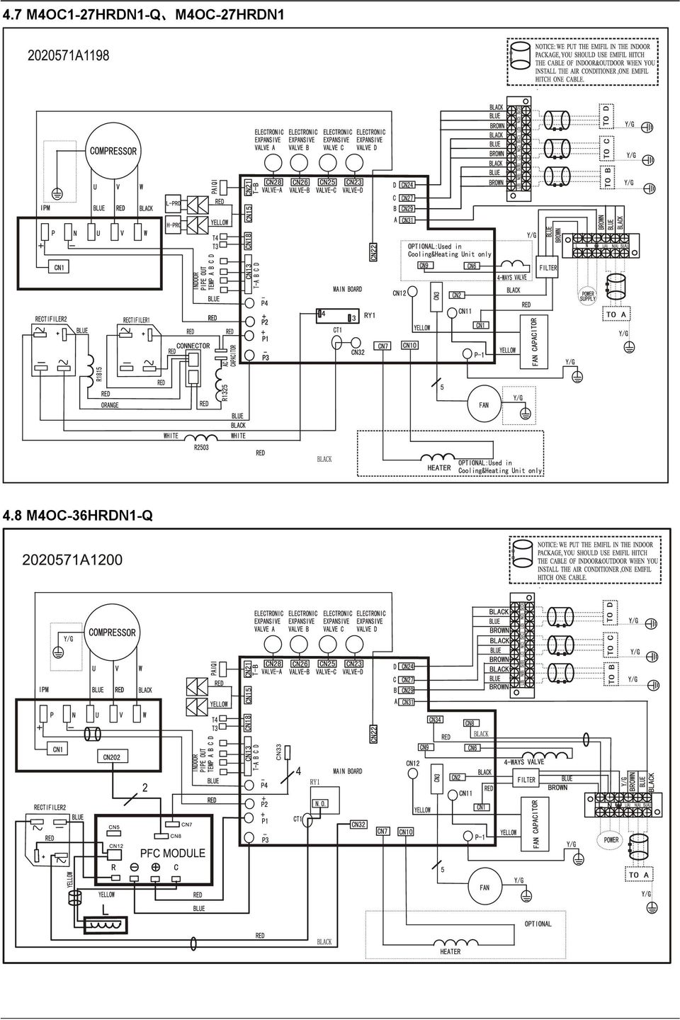
9 4.7 M4OC1-27HRDN1-Q M4OC-27HRDN1 4.8 M4OC-36HRDN1-Q
10 4.9 M5OA-36HRDN1-Q

11 5. Refrigeration Cycle Diagram 5.1 Refrigeration circuit drawing of inverter binary type 4.2 Refrigeration circuit drawing of inverter trinary type 5.3 Refrigeration circuit drawing of inverter quadplex type

12 5.4 Refrigeration circuit drawing of inverter quintuple type

13 6. Indoor units combination 6.1 Indoor unit combination for M2OC-14HRDN1-Q M2OC-14HRDN1 One unit Two unit te: There should be no more than one cassette or duct or console or ceiling & floor unit. 6.2 Indoor unit combination for M2OC1-18HRDN1-Q M2OC-18HRDN1 One unit Two unit te: The 18k indoor unit should only be wall mounted unit. 6.3 Indoor unit combination for M3OC1-21HRDN1-Q One unit Two unit Three unit te: There should be no more than one cassette or duct or console or ceiling & floor unit. And the 18k indoor unit should only be wall mounted unit. 6.4 Indoor unit combination for M3OC1-27HRDN1-Q M3OC-27HRDN1 One unit Two unit Three unit te: The 18k indoor unit should only be wall mounted unit. 6.5 Indoor unit combination for M4OC-24HRDN1-Q One unit Two unit Three unit Four unit te: The 18k indoor unit should only be wall mounted unit.

14 6.6 Indoor unit combination for M4OC1-27HRDN1-Q M4OC-27HRDN1 One unit Two unit Three unit Four unit Indoor unit combination for M4OC-36HRDN1-Q One unit Two unit Three unit Four unit Indoor unit combination for M5OA-36HRDN1-Q One Unit Two Unit Three Unit Four Unit Five Unit

15 7. Electronic control function 7.1 Abbreviation T1: Indoor ambient temperature T2: Coil temperature of indoor heat exchanger middle. T2B: Coil temperature of indoor heat exchanger outlet. T3: Coil temperature of outdoor heat exchanger T4: Outdoor ambient temperature T5: Compressor discharge temperature Ts: Setting temp. 7.2 Electric Control working environment Input voltage: 190~264V Input power frequency:50hz Indoor fan normal working amp. is less than 1A Outdoor fan. rmal working amp. is less than 1.5A Four-way valve normal working amp. is less than 1A Swing motor: DC12V. 7.3 Outdoor unit s digital display tube There is a digital display tube in outdoor PCB. Digital display tube display function In standby, the LED displays - - In compressor operation, the LED display the running frequency, In defrosting mode, The LED displays df or alternative displays between running frequency and df (each displays 2s) In compressor pre-heating, The LED displays - - In protection or malfunction, the LED displays error code or protection code. 7.4 Outdoor unit point check function There is a check switch in outdoor PCB. Push the switch SW1 to check the states of unit when the unit is running. The digital display tube will display the follow procedure when push SW1 each time. For units except M5OA-36HRDN1-Q model: Display 1 Indoor unit capacity demand code Remark 2 Outdoor unit running mode code Off:0, Cooling:1, Heating:2 3 Amendatory capacity demand code 4 Outdoor unit fan motor state Off:0, Low speed:1, High speed:2 5 Evaporator outlet temp. for 1# indoor unit Actual data 6 Evaporator outlet temp. for 2# indoor unit Actual data 7 Evaporator outlet temp. for 3# indoor unit Actual data 8 Evaporator outlet temp. for 4# indoor unit Actual data 9 Condenser pipe temp. Actual data 10 Ambient temp. Actual data 11 Compressor discharge temp. Actual data 12 Inverter current Actual data

16 13 EXV open angle for 1# indoor unit Actual data/8 14 EXV open angle for 2# indoor unit Actual data/8 15 EXV open angle for 3# indoor unit Actual data/8 16 EXV open angle for 4# indoor unit Actual data/8 17 Power supply of outdoor unit AD data 18 Indoor unit number The indoor unit can communicate with outdoor unit well. 19 The last error or protection code 00 means no malfunction 20 frequency value Actual data 21 Ambient temp. of 1# indoor unit Actual data 22 Condenser pipe temp. of 1# indoor unit Actual data 23 Ambient temp. of 2# indoor unit Actual data 24 Condenser pipe temp. of 2# indoor unit Actual data 25 Ambient temp. of 3# indoor unit Actual data 26 Condenser pipe temp. of 3# indoor unit Actual data 27 Ambient temp. of 4# indoor unit Actual data 28 Condenser pipe temp. of 4# indoor unit Actual data 29 Check point over For M5OA-36HRDN1-Q model: Display Remark 1. of indoor units in good connection Actual data 2 Outdoor unit running mode code Off:0, Cooling:2, Heating:3, Forced cooling:4 3 A indoor unit capacity 4 B indoor unit capacity 5 C indoor unit capacity 6 D indoor unit capacity 7 E indoor unit capacity 8 A Indoor unit capacity demand code 9 B Indoor unit capacity demand code 10 C Indoor unit capacity demand code 11 D Indoor unit capacity demand code 12 E Indoor unit capacity demand code 13 Total indoor units amendatory capacity demand code 14 The frequency corresponding to the total indoor units amendatory capacity demand 15 The frequency after the frequency limit 16 The frequency sending to compressor control chip 17 A indoor unit evaporator outlet temp.(t 2BA) 18 B indoor unit evaporator outlet temp.(t 2BB) 19 C indoor unit evaporator outlet temp.(t 2BC) 20 D indoor unit evaporator outlet temp.(t 2BD) 21 E indoor unit evaporator outlet temp.(t 2BE) 22 A indoor unit room temp.(t 1A) 23 B indoor unit room temp.(t 1B) 24 C indoor unit room temp.(t 1C) 25 D indoor unit room temp.(t 1D) 26 E indoor unit room temp.(t 1E) The capacity unit is horse power. If the indoor unit is not connected, the digital display tube will show: If the temp. is lower than -9 degree, the digital display tube will show -9.If the temp. is higher than 70 degree, the digital display tube will show 70. If the indoor unit is not connected, the digital display tube will show:

17 27 A indoor unit evaporator outlet temp.(t 2BA) 28 B indoor unit evaporator outlet temp.(t 2BB) 29 C indoor unit evaporator outlet temp.(t 2BC) 30 D indoor unit evaporator outlet temp.(t 2BD) 31 E indoor unit evaporator outlet temp.(t 2BE) 32 Condenser pipe temp.(t3) 33 Outdoor ambient temp.(t4) If the temp. is lower than -9 degree, the digital display tube will show -9.If the temp. is higher than 70 degree, the digital display tube will show 70. If the indoor unit is not connected, the digital display tube will show: 34 Compressor discharge temp.(tp) The display value is between 30~120 degree. If the temp. is lower than 30 degree, the digital display tube will show 30.If the temp. is higher than 99 degree, the digital display tube will show single digit and tens digit. For example, the digital display tube show 0.5,it means the compressor discharge temp. is 105 degree.) 35 AD value of current 36 AD value of voltage The display value is hex number. 37 EXV open angle for A indoor unit 38 EXV open angle for B indoor unit 39 EXV open angle for C indoor unit 40 EXV open angle for D indoor unit 41 EXV open angle for E indoor unit 42 Frequency limit symbol Actual data/4. If the value is higher than 99, the digital display tube will show single digit and tens digit. For example,the digital display tube show 2.0,it means the EXV open angle is 120 4=480p.) Bit7 0 The display value is hex Bit6 0 number. For Bit5 Frequency limit caused by T4. example, the digital display Bit4 Frequency limit caused by T2. tube show Bit3 Frequency limit caused by T3. 2A,then Bit5=1, Bit3=1, Bit1=1. Bit2 Frequency limit caused by Tp. It means frequency limit Bit1 Frequency limit caused by current caused by T4,T3 and Bit0 Frequency limit caused by voltage current. 43 Average value of T2 (Sum T2 value of all indoor units)/(indoor units number) 44 Outdoor unit fan motor state Off:0, High speed:1, Med speed:2, Low speed:3 45 The last error or protection code 00 means no malfunction Frequency of compressor: Display Frequency of compressor (Hz) Stand by Running mode: Display Corresponding mode 0 Off 1 Cooling mode 2 Heating mode
 The display value is between 30~120 degree. If the temp. is lower than 30 degree, the digital display tube will show 30.If the temp. is higher than 99 degree, the digital display tube will show single digit and tens digit.")
18 7.4.3 Capacity demand: Cooling mode Capacity Correspondi ng Code Heating mode Capacity Correspondin g Code > >= te: The capacity is just for reference > >=11

19 7.4.4Number of indoor unit Display Number of indoor unit Outdoor ambient temp: Display Corresponding temp. Display Corresponding temp. Display Corresponding temp ~ ~ ~ ~ ~ ~ ~

20 7.4.6 Opening degree of electronic expansion valve: Opening degree equals the display data times Protection Three minutes delay at restart for compressor Temperature protection of compressor discharge. rules: When the compressor discharge temp. is getting higher, the running frequency will be limited as below ----If 102 <T5<115, decrease the frequency to the lower level every 2 minutes till to F1. ---If T5>115 for 10 seconds, the compressor will stop and restart till T5< Under voltage protection VOLTAGE limit VOLREL1 VOLLIMT1 VOLLIMT2 VOLLIMT3 VOLFRE1 VOLFRE2 Off VOLREL2 VOLREL3 Mode VOLLIMT1(V) VOLLIMT2(V) VOLLIMT3(V) VOLREL1(V) VOLREL2(V) VOLREL3(V) VOLFRE1(Hz) VOLFRE2(Hz) M2OC-14HRDN M2OC-14HRDN1-Q M2OC-18HRDN M2OC1-18HRDN1-Q M3OC1-21HRDN1-Q M3OC-27HRDN M3OC1-27HRDN1-Q M4OC-24HRDN1-Q M4OC-27HRDN M4OC1-27HRDN1-Q M4OC-36HRDN1-Q For M5OA-36HRDN1-Q, VOLTAGE limit VOLT_RST1_ADD VOLT_LTM1_ADD VOLT_LTM_FREQ1_ADD VOLT_RST2_ADD VOLT_LTM2_ADD VOLT_LTM_FREQ2_ADD

21 VOLT_RST1_ADD=210V, VOLT_LIM1_ADD=200V, VOLT_RST2_ADD=195V, VOLT_LIM2_ADD=185V. VOLT_LIM_FREQ1_ADD=54Hz, VOLT_LIM_FREQ2_ADD=42Hz Compressor current limit protection If the compressor current exceeds the current limit value for 10 seconds, the compressor frequency will be limited as below table. For models except M5OA-36HRDN1-Q. Cooling mode: Current frequency(hz) Current limit value(a) Frequency limit COOL_F10 ICOOLLMT6 Decrease the frequency to COOL_F4 and COOL_F9 ICOOLLMT5 run at COOL_F4 for 3 minutes. COOL_F8 COOL_F7 COOL_F6 COOL_F5 ICOOLLMT4 ICOOLLMT3 ICOOLLMT2 ICOOLLMT1 After that, the frequency will be adjusted according to the capacity demand and rise to the upper level every 3 minutes (When the frequency>cool_f4 via capacity demand). If the current frequency is lower than COOL_F4, the frequency will not be limited. After 10s of the compressor start, if the current>icool, the AC will display the failure for 30 seconds and stop. The AC will restart 3 minutes later. Heating mode: Current frequency(hz) Current limit value(a) Frequency limit HEAT_F12 IHEATLMT8 Decrease the frequency to HEAT_F4 and HEAT_F11 IHEATLMT7 run at HEAT_F4 for 3 minutes. HEAT_F10 HEAT_F9 HEAT_F8 HEAT_F7 HEAT_F6 HEAT_F5 IHEATLMT6 IHEATLMT5 IHEATLMT4 IHEATLMT3 IHEATLMT2 IHEATLMT1 After that, the frequency will be adjusted according to the capacity demand and rise to the upper level every 3 minutes (When the frequency>heat_f4 via capacity demand). If the current frequency is lower than HEAT_F4, the frequency will not be limited. After 10s of the compressor start, if the current>iheat, the AC will display the failure for 30 seconds and stop. The AC will restart 3 minutes later. For M5OA-36HRDN1-Q model: Cooling mode: Current (Hz) frequency Current limit value(a) Frequency limit COOL_F16 ICOOLLMT12 Decrease the frequency to COOL_F4 and run at COOL_F15 ICOOLLMT11 COOL_F4 for 3 minutes. COOL_F14 COOL_F13 COOL_F12 COOL_F11 COOL_F10 ICOOLLMT10 ICOOLLMT9 ICOOLLMT8 ICOOLLMT7 ICOOLLMT6 After that, the frequency will be adjusted according to the capacity demand and rise to the upper level every 3 minutes (When the frequency>cool_f4 via capacity demand).
22 COOL_F9 COOL_F8 COOL_F7 COOL_F6 COOL_F5 ICOOLLMT5 ICOOLLMT4 ICOOLLMT3 ICOOLLMT2 ICOOLLMT1 If the current frequency is lower than COOL_F4, the frequency will not be limited. After 10s of the compressor start, if the current>icool, the AC will display the failure for 30 seconds and stop. The AC will restart 3 minutes later. Heating mode: Current frequency Current limit value(a) Frequency limit (Hz) HEAT_F16 HEAT_F15 IHEATLMT12 IHEATLMT11 Decrease the frequency to HEAT_F4 and run at HEAT_F4 for 3 minutes. HEAT_F14 HEAT_F13 HEAT_F12 HEAT_F11 HEAT_F10 HEAT_F9 HEAT_F8 HEAT_F7 HEAT_F6 HEAT_F5 IHEATLMT10 IHEATLMT9 IHEATLMT8 IHEATLMT7 IHEATLMT6 IHEATLMT5 IHEATLMT4 IHEATLMT3 IHEATLMT2 IHEATLMT1 After that, the frequency will be adjusted according to the capacity demand and rise to the upper level every 3 minutes (When the frequency>heat_f4 via capacity demand). If the current frequency is lower than HEAT_F4, the frequency will not be limited. After 10s of the compressor start, if the current>iheat, the AC will display the failure for 30 seconds and stop. The AC will restart 3 minutes later Indoor / outdoor units communication protection If the indoor units can not receive the feedback signal from the outdoor units for 2 minutes, the AC will stop and display the failure High condenser coil temp. protection. When T3>65 for 3 seconds, the compressor will stop while the indoor fan and outdoor fan will continue. When T3<52, the protection will release and the compressor will restart after 3 minutes Outdoor unit anti-freezing protection When T2B<0 for 250 seconds, the indoor unit capacity demand will be zero and resume to normal when T2B> Oil return Running rules:
23 1. If the compressor frequency keeps lower than RECOILINFRE for Te minutes, the AC will rise the frequency to RECOILFRE for Tf seconds and then resume to former frequency. For M4OC-36HRDN1-Q, RECOILINFRE=45Hz, RECOILFRE=48Hz,Te=120,Tf=180; For M5OA-36HRDN1-Q, RECOILINFRE=45Hz, RECOILFRE=48Hz, Te=90,Tf=100; For other models, RECOILINFRE=50Hz, RECOILFRE=62Hz, Te=120,Tf= During the Tf seconds, the EXV and indoor units keep the current running mode(except M5OA-36HRDN1-Q model), the frequency will not be limited by the compressor discharge temp. and the current. For M5OA-36HRDN1-Q model, the EXV will keep 300p while the indoor units will keep the current running mode. 3. If the outdoor ambient is higher than 15 during the oil return, the AC quit oil return Compressor preheating functions ----Preheating permitting condition: If T4(outdoor ambient temperature)<3 and the machine connects to power supply no longer than 5 seconds or if T4<3 and compressor has stopped for over 3 hours, the compressor heating cable will work. ----Preheating mode: A weak current flow through the coil of compressor from the wiring terminal of compressor, then the compressor is heated without operation. ----Preheating release condition: If T4 5 or the compressor starts running, preheating function will stop Compressor crankcase heater When T4<3 and the compressor is not running, the crankcase heater will be active. When T4 5 or the compressor starts up, the crankcase heater will stop work.(for M5OA-36HRDN1-Q,T4 8 )
24 8. Troubleshooting 8.1 Indoor unit error code explanation: Glory series NO. MALFUNCTION DEF TIMER AUTO RUN 1 Indoor EEPROM malfunction O O O O 2 Indoor / outdoor units communication error 3 Zero-crossing signal error O O 4 Indoor fan speed has been out of control O O 5 Open circuit or short circuit of outdoor temperature sensor X O X 6 Open circuit or short circuit of T1 or T2 temperature sensor O O O 8 IPM module protection or IGBT over-strong current protection X X O 9 Over voltage or too low voltage protection X O O 10 Temperature protection of compressor top O X X 11 Inverter compressor drive protection O X 12 Mode conflict X O Flash(at 0.5Hz, Mode conflict at 0.25Hz) O light X(off) 9V series+vertu series+9a series+corona series+ R series+y series+ X series Display E0 E1 E2 E3 E5 E6 P0 P1 P2 P4 P5 LED STATUS Indoor EEPROM malfunction Indoor/ outdoor units communication error Zero-crossing signal error Indoor fan speed has been out of control Open circuit or short circuit of outdoor temperature sensor Open circuit or short circuit of T1 or T2 temperature sensor IPM module protection or IGBT over-strong current protection Over voltage or too low voltage protection Temperature protection of compressor top Inverter compressor drive protection Mode conflict NEOLA series +PREMIER series +OASIS series: Display Operation lamp flash times Timer lamp Failure E0 1 X Indoor EEPROM malfunction E1 2 X Indoor / outdoor units communication error E2 3 X Zero-crossing signal error E3 4 X Indoor fan speed has been out of control E4 5 X Open or short circuit of T1 temperature sensor E5 6 X Open or short circuit of T2 temperature sensor F1 2 O Open or short circuit of T4 temperature sensor
25 F2 3 O Open or short circuit of T3 temperature sensor F3 4 O Open or short circuit of T5 temperature sensor F4 5 O Outdoor EEPROM malfunction F6 7 O Open or short circuit of T2B temperature sensor P0 1 IPM module protection or IGBT over-strong current protection P1 2 Over voltage or too low voltage protection P2 3 Temperature protection of compressor top P4 5 Inverter compressor drive protection P5 6 Mode conflict O (light) X (off) (flash) Cassette series: Operation Timer De-frost Alarm LED STATUS X X X Open or short circuit of T1 temperature sensor X X X Open or short circuit of T2 temperature sensor X X X Indoor / outdoor units communication error X X X Full-water malfunction X X Indoor EEPROM malfunction X X IPM module protection X X Open or short circuit of T3 or T4 temperature sensor X Outdoor voltage protection Temperature protection of compressor top X Mode conflict X Inverter compressor drive protection Ceiling &Floor series: flash, light, X extinguished. Operation Timer De-frost Alarm LED STATUS X X X Open or short circuit of T1 temperature sensor X X X Open or short circuit of T2 temperature sensor X X X Indoor / outdoor units communication error X X X Full-water malfunction X X Indoor EEPROM malfunction X X IPM module protection X X Open or short circuit of T3 or T4 temperature sensor X Outdoor voltage protection X X Temperature protection of compressor top X Mode conflict flash, light, X extinguished.
26 A5 Duct series: Operation Timer De-frost Alarm LED STATUS DISPLAY DIGITAL TUBE X X X Open or short circuit of T1 temperature sensor E0 X X X Open or short circuit of T2 temperature sensor E1 X X X Indoor / outdoor units communication error E2 X X X Full-water malfunction E3 X X Indoor EEPROM malfunction E4 X X IPM module protection E5 X X Open or short circuit of T3 or T4 temperature sensor X Outdoor voltage protection P0 Temperature protection of compressor top P3 X X Inverter compressor drive protection P4 X X Mode conflict P5 flash at 5Hz, light, X extinguished flash at 0.5Hz E6 Console series: Operation Timer De-frost LED STATUS X X Open or short circuit of T1 temperature sensor X X Open or short circuit of T2 temperature sensor X X Indoor / outdoor units communication error X Indoor EEPROM malfunction X IPM module protection Open or short circuit of T3 or T4 temperature sensor X Top temperature protection of compressor X Inverter compressor drive protection X Mode conflict Indoor fan speed has been out of control flash at 5Hz, light, X extinguished
27 Outdoor unit error code explanation: For units(except M5OA-36HRDN1-Q model) Display LED STATUS E0 E1 E2 E3 E6 E4 E5 E7 Outdoor EEPROM malfunction A Indoor unit coil outlet temp. sensor or connector of sensor is defective B Indoor unit coil outlet temp. sensor or connector of sensor is defective C Indoor unit coil outlet temp. sensor or connector of sensor is defective D Indoor unit coil outlet temp. sensor or connector of sensor is defective Open or short circuit of outdoor unit temperature sensor Compressor voltage protection Communication malfunction between IPM board and outdoor main board Temperature protection of compressor discharge or compressor top. P0 For M4OC-27HRDN1, M4OC1-27HRDN1-Q,M4OC-36HRDN1-Q,it only means Temperature protection of compressor discharge P1 P2 P3 P4 P6 P7 High pressure protection(only for M4OC1-27HRDN1-Q, M4OC-27HRDN1-Q,M4OC-36HRDN1-Q) Low pressure protection(only for M4OC1-27HRDN1-Q, M4OC-27HRDN1-Q,M4OC-36HRDN1-Q) Current protection of compressor IPM module protection High temperature protection of condenser Inverter compressor drive protection
28 For M5OA-36HRDN1-Q model Display LED STATUS E0 E2 E3 E4 E5 E6 F1 F2 F3 F4 F5 P1 P2 P3 P4 P5 P6 Outdoor EEPROM malfunction Indoor / outdoor units communication error Communication malfunction between IPM board and outdoor main board Open or short circuit of outdoor unit temperature sensor Compressor voltage protection PFC module protection A Indoor unit coil outlet temp. sensor or connector of sensor is defective B Indoor unit coil outlet temp. sensor or connector of sensor is defective C Indoor unit coil outlet temp. sensor or connector of sensor is defective D Indoor unit coil outlet temp. sensor or connector of sensor is defective E Indoor unit coil outlet temp. sensor or connector of sensor is defective High pressure protection Low pressure protection Current protection of compressor Temperature protection of compressor discharge High temperature protection of condenser IPM module protection
29 8.3Trouble shooting For the indoor unit Indoor EEPROM malfunction
30 Indoor / outdoor units communication error Start: Power off, then Power on the A/C by the Breaker. (reconnect the power wire). Is E1 extinguish? Check wiring on the outdoor and indoor terminal follow the wiring diagram. Is all connecting correctly? Reconnect the wiring Reconnect the wiring Turn on all indoor unit by remote controller. Is all indoor unit display Measure Vs, is it moving alternately between positive value and negative value? (Vs is the voltage between S and L2). Refer PIC 1 Turn off the all indoor units. Is IPM power LED lamp On? Refer PIC 3 change IPM A: Is all the wiring between terminal and Indoor PCB connect ok? Is PFC power LED lamp off? Refer PIC 3. change PFC change the Indoor PCB Reconnect the wiring Power on by remote controller, Is the E1 extinguish after 3 minutes? Is Main board " lamp on? Refer PIC 4. Is the Reactor connection. Is indoor units number correct? Check on the outdoor check point (18). (2 for dual zone, 3 for tri zone, 4 for qua zone). Refer PIC 5. Change Outdoor Main PCB E1 error problem solved. The unit operation normally. fist time Change outdoor unit PCB assembly(include wiring) totally second time A
31 Pic 1: Measure the voltage of L2 to S (Vs), is it moving alternately between positive value and negative value? PIC 2, Check the wiring. PIC 3:IPM (For dual/tri/qua-zone) PFC (qua-zone only) Off is OK Power on Self-Check OK Operati PIC4 :Main board LED when power on and unit standby. PIC 5: check piont buttom, pess 18 times for check how many indoor units are connected.
32 Zero-crossing signal error Indoor fan speed has been out of control Shut off the power supply and turn it on 1 minute later. Is it still displaying the error code? The unit operates normally. S h u t o f f t h e p o w e r supply, rotate the cross fan by hand. Does it rotate properly? Disassembly the connection between fan and motor, check if the bearing is normal? Replace the bearing. Check the wires of fan motor. Are all the connections good? Correct the connections. Replace indoor fan motor. Check the resistance value of indoor fan motor, is it normal? Replace indoor PCB.
33 Open or short circuit of temperature sensor Full-water malfunction Full-water malfunction Check whether the water-level switch is inserted well Insert the water-level switch well Check whether the water-level switch is broken Replace the water-level switch Check whether the water pump is normal Replace the water pump Check PCB board or replace the indoor main PCB
34 8.3.2 For the outdoor unit Outdoor EEPROM malfunction Outdoor EEPROM malfunction If the EEPROM chip is welded on PCB, replace the PCB directly. Otherwise, check whether the EEPROM chip plugged in PCB well? Insert the EEPROM well Replace the outdoor main board
35 Voltage protection of compressor Voltage protection of compressor Check the voltage of outdoor unit power supply, whether the voltage between L(1) and N is about 220VAC Check the power supply Replace the power board, then check whether the system can run normally Trouble is solved Check whether the voltage of IPM board P and N is VDC Replace bridge rectifiers, then check whether the system can run normally Trouble is solved Replace IPM board Replace outdoor main board
36 Communication malfunction between IPM board and outdoor main board Check whether the IPM board has error display Replace IPM board Insert the connecting wiring between the IPM module and the main board well over again Trouble is solved Replace the IPM board Trouble is solved Replace outdoor PCB Trouble is solved The problem is not resolved. Replace the electric control box
37 Temperature protection of compressor discharge Discharge temperature protection of compressor Check whether the compressor discharge temp. is more than 115 C? Check whether the wiring connection is right between compressor discharge temp. sensor and PCB according to wiring diagrams Correct the wiring connection Judge: The discharge temp. sensor is broken Check whether the refrigerant is leak Stop leaking and add refrigerant Method: Check whether the resistance of compressor discharge temp. sensor is right refer to the Appendix 2 Replace the compressor discharge temp. sensor Replace outdoor main board
38 Temperature protection of compressor top Temperature protection of compressor top Judge 1: Whether compressor operates? Whether the connection is good? Reconnect retest. and Judge 2: Whether refrigerant circulation volume is normal? Whether protector is normal? Replace the protector. Method: Charge refrigerant Check the outdoor main PCB. Is there some problem? Replace the outdoor main PCB Whether abnormality is the same after gas charging? Check refrigerant system (such as clogging of capillary etc.)
39 High pressure protection(for M4OC1-27HRDN1-Q, M4OC-27HRDN1-Q,M4OC-36HRDN1-Q, M5OA-36HRDN1-Q) High pressure protection Judge 1: Whether the wiring between the high pressure switch and main control board is connected well or correctly Connect it well Judge 2: Whether the high pressure switch is broken Method: Short connect the high pressure switch socket, check whether the system can run normally Replace high pressure switch Check whether the refrigerant system is ok Judge 3: Check whether the outdoor ambient temperature is too high Stop the unit Judge 4: Check whether the outdoor unit is bad ventilation Make the outdoor unit ventilate well Judge 5: Check whether the heat exchanger is dirty Clean the heat exchanger Judge 6: Check whether the refrigerant pipe is blocked Let the refrigerant out, then use the high pressure nitrogen or refrigerant to blow pipe, vacuumize and charge the refrigerant again Replace outdoor main board
40 Low pressure protection (For M4OC1-27HRDN1-Q, M4OC-27HRDN1-Q,M4OC-36HRDN1-Q, M5OA-36HRDN1-Q) Low pressure protection Judge 1: The wiring between the low pressure switch and main control board is connected well or correctly Connect it well Judge 2: Whether the low pressure switch is broken Method: Short connect the low pressure switch socket, check whether the system can run normally Replace low pressure switch Check whether the refrigerant system is ok Judge 3: Check whether the outdoor ambient temperature is too low Stop the unit Judge 4: The refrigerant of the system is leakage Method: Connect the pressure gauge to the gauge joint of the system, check whether the pressure is lower than 0.14MPa Leak hunting: Charge nitrogen or refrigerant to the system, if the leakage is serious, there will be distinct gas leakage cici sound; if the leakage is slight, use the suds (mixture of water and abluent is also ok if it can make bubble) or electronic leak detector. Judge 5: The refrigerant pipe is blocked Let the refrigerant out, then use the high pressure nitrogen or refrigerant to blow pipe, vacuumize and charge the refrigerant again Replace outdoor main board
41 Current protection of compressor Current protection of compressor Judge 1: Check whether the input current of the power supply wire is more than 8.5A (For 18-21K, it is 15A..For 27K(1x3), it is 15A.For 27K(1x4), it is 18.5A, For 36K, it is 21.5A) Check whether the refrigerant system is ok Judge 2: Check whether the outdoor ambient temperature is too high Stop the unit Judge 3: Check whether the outdoor unit is bad ventilation Make the outdoor unit ventilate well Judge 4: Check whether the heat exchanger is dirty Clean the heat exchanger Judge 5: The refrigerant pipe is blocked Let the refrigerant out, then use the high pressure nitrogen or refrigerant to blow pipe, vacuumize and charge the refrigerant again Replace outdoor main board Trouble is solved The problem is not resolved. Replace the electric control box
42 IPM module protection IPM module protection Check whether the voltage range of P-N on IPM module is normal? DC V for 14-27KBtu/h; DC V for 36KBtu/h Check whether the input power supply is correct? V, 1N, 50Hz Regulate it to correct, then check whether the system can work normally? Check whether the connecting line between main board and the IPM module is connected tightly Connect it tightly, check ok or not? Check whether the power supply line is connected correctly and tightly Connect it correctly and tightly, check ok or not? Check whether the connecting line of the compressor is connected correctly or tightly Connect it well, check ok or not? Check whether the lines in E-part box are connected tightly Connect it tightly, check ok or not? Replace the IPM module, check whether the system can work normally? Check whether the single-phase bridge is normal? Use the multimeter to measure the resistance between each two terminals, check whether there is the condition that value of resistance is 0 Replace the single-phase bridge Trouble is solved Replace the main board, check whether the system can work normally? Trouble is solved Check whether the connecting line of every reactor is normal? If the line is broken, the resistance of the two ports is (models except for M5OA-36HRDN1-Q);Check whether the PFC module broken(for M5OA-36HRDN1-Q) Replace the connecting line or reactor or replace the PFC module Replace the compressor, check whether the system can work normally? Trouble is solved
43 High temperature protection of condenser When outdoor pipe temp. is more than 65 C, the unit will stop, and unit runs again when outdoor pipe temp. less than 52 C. High temperature protection of condenser Check whether the condenser temperature is more than 65 C Check whether the resistance of condenser temp. sensor is correct refer to the Appendix 1 Replace the temperature sensor Replace outdoor main board Stop the unit Judge1: The outdoor temp. is too high Clean the heat exchanger Judge 2: Check whether the heat exchanger is dirty Let the refrigerant out, then use the high pressure nitrogen or refrigerant to blow pipe, vacuumize and charge the refrigerant again Judge 3: The refrigerant pipe is blocked
44 PFC module protection PFC module protection Check whether the connecting line between main board and the PFC module is connected tightly Connect it tightly, check normal or not Check whether the voltage between P and N of IPM module is VDC Replace the outdoor main board Check whether the inductance of PFC module is good? Replace the PFC module Replace the inductance Inverter compressor drive protection The trouble shooting is same with one of IPM module protection
45 Appendix 1 Temperature Sensor Resistance Value Table ( --K) K Ohm K Ohm K Ohm K Ohm
46 Appendix 2 Unit: ---K Discharge temp. sensor table B(25/50)=3950K R(90 )=5KΩ±3%
47 Appendix 3 1. Reference voltage data: a) Rectifier : Input : V(AC), output :310V(DC) b) Inverter module: U,V, W 3ph. Result U-V U-W V-W P-N V(AC) V(AC) V(AC) DC 310V 2. Check the Diode Bridge component ( In wiring diagram, rectifier) Remark: If this part is abnormal, the LED will not light. ~ + - ~ Multi-meter Result Forward Resistance Backward Resistance + _ Infinite Infinite ~ ~1.7M ohm Infinite ~ + - ~ ~1.7M ohm Infinite ~
SERVICE MANUAL. Room Air Conditioner Multi Split type Outdoor unit /R410A DC Inverter/
 SERVICE MANUAL Room Air Conditioner Multi Split type Outdoor unit /R410A DC Inverter/ FS2MI-147HFD FS2MI-187HFD FS3MI-217HFD FS3MI-277HFD FS4MI-277HFD FS4MI-367HFD FS5MI-367HFD NOTE: Before servicing the
TAS-18MVHN/O TAS-27MVHN/O TAS-36MVHN/O
 SERVICE MANUAL AIRCONDITIONER DC INVERTER MULTI TYPE TAS-18MVHN/O TAS-27MVHN/O TAS-36MVHN/O DC MULTI OUTDOOR UNITS CONTENTS 1. General information of Outdoor Units... 3 2. Dimensions... 4 3. Wiring Diagram...
Technical service manual 2009
 MULTI SPLIT TYPE, HEAT PUMP AIR CONDITIONERS Technical service manual 2009 KSIM MULTI ZONE SERIES R410A DC Inverter multi Series Models KSIM20912-H216 KSIM30912-H216 KSIM40912-H216 CONTENT 1. Product features
13. Troubleshooting. Indoor unit s LED indication of Corona DC inverter unit. Indoor unit s LED indication of Alfa DC inverter unit
 Troubleshooting 13. Troubleshooting Indoor unit s LED indication of Corona DC inverter unit MCAC-HTSM-2007-11 E0 E1 E2 E3 E5 E6 P0 P1 P2 P3 P5 EEPROM error outdoor communication error Zero-crossing examination
Failure code manual. content
 Failure code manual content 一 wall split AC series 2 二 floor standing AC series. 4 三 portable AC series.. 5 四 dehumidifer 6 五 DC inverter single split series...7 六 DC inverter multi-split series 10 1 一
Service manual. The voltage in P3 and P4 in outdoor PCB is high voltage about 310V The voltage in P5 and P6 in outdoor PCB is high voltage about 310V
 Resistance The voltage in P3 and P4 in outdoor PCB is high voltage about 310V The voltage in P5 and P6 in outdoor PCB is high voltage about 310V 9.2 Troubleshooting for indoor unit E0 E1 E2 E3 E5 E6 P0
SERVICE INSTRUCTION R410A. WALL MOUNTEDtype INVERTER SPLIT TYPE ROOM AIR CONDITIONER. Models Indoor unit Outdoor unit
 SERVICE INSTRUCTION SPLIT TYPE ROOM AIR CONDITIONER WALL MOUNTEDtype INVERTER Models Indoor unit Outdoor unit ASYG07LECA ASYG09LECA ASYG12LECA ASYG14LECA AOYG07LEC AOYG09LEC AOYG12LEC AOYG14LEC R410A CONTENTS
SERVICE INSTRUCTION R410A. SPLIT TYPE ROOM AIR CONDITIONER Universal Floor / Ceiling Duct / Cassette Wall Mounted / Floor type INVERTER MULTI
 SERVICE INSTRUCTION SPLIT TYPE ROOM AIR CONDITIONER Universal Floor / Ceiling Duct / Cassette Wall Mounted / Floor type INVERTER MULTI R410A Models Indoor unit Outdoor unit AB*14LBAJ AB*18LBAJ AB*F14LAT
SERVICE MANUAL. Room Air Conditioner Multi Split Wall-Mounted Type Indoor. FSAI-Pro-91AE2 FSAI-Pro-121AE2 FSAIF-Pro-181AE2
 SERVICE MANUAL Room Air Conditioner Multi Split Wall-Mounted Type Indoor FSAI-Pro-91AE2 FSAI-Pro-121AE2 FSAIF-Pro-181AE2 NOTE: Before servicing the unit, please read this at first. Always contact with
SERVICE INSTRUCTION R410A. WALL MOUNTEDtype SPLIT TYPE ROOM AIR CONDITIONER INVERTER. Models Indoor unit Outdoor unit AOU 9RLFW AOU12RLFW AOU15RLS
 SERVICE INSTRUCTION SPLIT TYPE ROOM AIR CONDITIONER WALL MOUNTEDtype INVERTER Models Indoor unit Outdoor unit ASU 9RLF ASURLF ASU5RLS AOU 9RLFW AOURLFW AOU5RLS R40A CONTENTS. DESCRIPTION OF EACH CONTROL
14. Troubleshooting Guide
 14. Guide 14.1 Refrigeration Cycle System In order to diagnose malfunctions, ensure the air conditioner is free from electrical problems before inspecting the refrigeration cycle. Such problems include
R22. K Control. Indoor Unit. Nomenclature. Compatibility PL H 3 G K H B. Unit style Heat Pump Horse Power
 R22. K Control. Indoor Unit. Nomenclature. PL H 3 G K H B Compatibility Unit style Heat Pump Horse Power Control Boost Heaters R22. K Control. Outdoor Unit. Nomenclature. PU H 3 Y K A Compatibility Outdoor
Service manual. Website: www.andico.com.au CAUTION - BEFORE SERVICING THE UNIT, READ THE SAFETY - PRECAUTIONS IN THIS MANUAL.
 Website: www.andico.com.au Service manual CAUTION - BEFORE SERVICING THE UNIT, READ THE SAFETY - PRECAUTIONS IN THIS MANUAL. - ONLY FOR AUTHORISED SERVICE PERSONNEL. MODELS: MPK1-09CR-QB8 MPK1-12ER-QB6
Midea Commercial Air Conditioner Malfunction Handbook
 Midea Commercial Air Conditioner Malfunction Handbook May 1, 2008 Customer Service Philosophy of Midea Air Conditioner Service Target: 100% Customer Satisfaction Service Standard: 100% Earnestness Service
9ASNA-A1-1202 SERVICE MANUAL SENVILLE AIRCONDITIONER DC INVERTER SPLIT WALL-MOUNTED TYPE
 9ASNA-A1-1202 SERVICE MANUAL SENVILLE AIRCONDITIONER DC INVERTER SPLIT WALL-MOUNTED TYPE CONTENTS 1. Precaution... 1 1.1 Safety Precaution... 1 1.2 Warning... 1 2. Function... 6 3. Dimension... 9 3.1 Indoor
Indoor coil is too warm in cooling mode or too cold in heating mode. Reversing valve or coil thermistor is faulty
 Codes Room Air Conditioner range: Indoor unit alarm s If timer lamp flashes for 1 second on, 1 second off, this indicates pre heating on the coil during heating mode and is not an error. If timer lamp
Si10-417_C. Pocket Manual. Service Diagnosis SPLIT & MULTI
 Pocket Manual Service Diagnosis SPLIT & MULTI Service Diagnosis SPLIT & MULTI 1. Troubleshooting with LED...5 1.1 Indoor Unit... 5 1.2 Outdoor Unit... 10 2. Troubleshooting by Symptoms...11 2.1 Air conditioner
CONTENTS 1. IMPORTANT NOTICE 2 2. TECHNICAL SPECIFICATION 3 3. OPERATION DETAILS 4 4. WIRING DIAGRAM 11 5. EXPLOSION VIEW 12 6.
 TCL WALL MOUNTED SPLIT-TYPE AIR CONDITIONERS SERVICE MANUAL No.TE051220 Models TAC-09CHSA/GI TAC-12CHSA/GI CONTENTS 1. IMPORTANT NOTICE 2 2. TECHNICAL SPECIFICATION 3 3. OPERATION DETAILS 4 4. WIRING DIAGRAM
LG Air Conditioning Multi F(DX) Fault Codes Sheet. Multi Split Units
 Fault Codes Sheet. Multi Split Units") Multi Split Units If there is a fault on any LG Multi unit, an Error mark is indicated on the display window of the indoor unit, wired-remote controller, and LED s of outdoor unit control board. A two
Multi Split Units If there is a fault on any LG Multi unit, an Error mark is indicated on the display window of the indoor unit, wired-remote controller, and LED s of outdoor unit control board. A two
LG Air Conditioning - Universal Split Fault Codes Sheet. Universal Split Systems
 Universal Split Systems If there is a fault on any LG Universal unit, a two digit number will appear on the remote controllers led display. If the unit does not have a remote controller the fault will
10.1 Indoor Unit Error Display
 10.1 Indoor Unit Error Display Display E0 E1 E2 E3 E5 E6 P0 P1 P2 P4 LED STATUS EEPROM parameter error Indoor / outdoor units communication protection Zero-crossing signal error Fan speed out of control
PANASONIC TROUBLE SHOOTING GUIDE
 A General Guide To Room Style Products Pipework Pipe sizes and lengths should be as the relevant Technical Guide Both lines should be insulated No line accessories or oil traps should be fitted In cooling
Model: AC-S13CG x 2. Model No: AC-S13CGx2.doc Version 1.0
 Air Conditioner Service Manual 2 3 Model: AC-S13CG x 2 3 Content Technical specification.. 4 Performance curve.5 Outline & dimension of indoor unit..10 Outline & dimension of outdoor unit 11 Exploded view
Haier Air conditioner
 For Europe Haier Air conditioner HAND in HAND HIGHER and HIGHER Page:1 For Europe HSU-09/12HVA103/R2(DB) HSU-09/12RHA103/R2(DB) Page:2 Error Codes and Description indoor and outdoor display(1) indoor Code
SERVICE MANUAL. Room Air Conditioner Split Wall-Mounted Type. FSAI-Pro-91AE2 / FSOAI-Pro-91AE2. FSAI-Pro-241AE2 / FSOAI-Pro-241AE2
 SERVICE MANUAL Room Air Conditioner Split Wall-Mounted Type FSAI-Pro-91AE2 / FSOAI-Pro-91AE2 FSAI-Pro-121AE2 / FSOAI-Pro-121AE2 FSAIF-Pro-181AE2 / FSOAIF-Pro-181AE2 FSAI-Pro-241AE2 / FSOAI-Pro-241AE2 NOTE:
543-0032-00, 943-0032-00. User s Manual
 543-0032-00, 943-0032-00 User s Manual 1 Comfort Alert Diagnostics Faster Service And Improved Accuracy The Comfort Alert diagnostics module is a breakthrough innovation for troubleshooting heat pump and
WALL MOUNTED AIR CONDITIONER SERVICE MANUAL 11M INVERTER
 WALL MOUNTED AIR CONDITIONER SERVICE MANUAL 11M INVERTER This manual applies to the models: 42HVM109303 / 38HVM109303(P) 42HVM112303 / 38HVM112303(P) 42HVM118303 / 38HVM118303(P) 42HVM124303 / 38HVM124303(P)
1 4. 3 4-2 ABNORMAL OPERATION. 4-2-1 Error code Display. Specifics Error Code. Subsection Error Code. Subsection and Specifics Error code target
 4-2 ABNORMAL OPERATI 4-2-1 An is represented by 3 digit characters. The first 2 digit means the subsection, and the last 1 digit means the specifics. Ex.) Indoor unit Network communication Error Subsection
WYS SERIES SPLIT 3D DC INVERTER HEAT PUMP / AIR CONDITIONER SERVICE MANUAL
 z WYS SERIES SPLIT 3D DC INVERTER HEAT PUMP / AIR CONDITIONER SERVICE MANUAL Revision A: 151110001, Content updated. Model Numbers: 17 SEER Family: WYS009AMFI17RL, WYS012AMFI17RL, WYS009GMFI17RL, WYS012GMFI17RL,
SERVICE MANUAL 12VDC WALL THERMOSTAT AIR CONDITIONING SYSTEMS ROOFTOP UNITS ONLY
 SERVICE MANUAL 12VDC WALL THERMOSTAT AIR CONDITIONING SYSTEMS ROOFTOP UNITS ONLY! WARNING - SHOCK HAZARD! TO PREVENT THE POSSIBILITY OF SEVERE PERSONAL INJURY, DEATH, OR EQUIPMENT DAMAGE DUE TO ELECTRICAL
Technical Service Manual. Version One
 [Gree Central Air Conditioner] Technical Service Manual Ducted type unit 2.3KW-16KW Version One GREE ELECTRIC APPLIANCES.INC.OF ZHUHAI - 1 - FG Series wind pipe blowing air-conditioning unit Section One:
CONTENTS 1. IMPORTANT NOTICE 2 2. TECHNICAL SPECIFICATION 3 3. OPERATION DETAILS 4 4. ELECTRICAL SCHEMATIC DIAGRAM 13 5. EXPLOSION VIEW 16 6
 TCL WALL MOUNTED SPLIT-TYPE AIR CONDITIONERS SERVICE MANUAL No.TE080528 Models KFTHP-12 KFTHP-18 KFTHP-24 CONTENTS 1. IMPORTANT NOTICE 2 2. TECHNICAL SPECIFICATION 3 3. OPERATION DETAILS 4 4. ELECTRICAL
SERVICE MANUAL SPLIT SYSTEM ROOM AIR CONDITIONER SHARP CORPORATION SHARP CORPORATION CONTENTS
 SERVICE MANUAL SPLIT SYSTEM ROOM AIR CONDITIONER INDOOR UNIT AH-129 AH-MP14 OUTDOOR UNIT AU-129 AU-MP14 CONTENTS SPECIFICATIONS...2 EXTERNAL DIMENSIONS...4 WIRING DIAGRAMS...5 ELECTRICAL PARTS...6 MICROCOMPUTER
Appendix - Controllers 179
 Version: 200703 Appendix - Controllers 179 -3- -4- -5- -6- -7- -8- 2. Specifications 2.1 Specifications for inverter units item Model AB182ACERA Function cooling heating Capacity kw 5.01.8--5.8 5.22.0---6.2
RMI-1103-A SERVICE MANUAL MIDEA AIRCONDITIONER EUROPE MARKET DC INVERTER MULTI TYPE R DC INVERTER MULTI SERIES
 RMI-1103-A SERVICE MANUAL MIDEA AIRCONDITIONER EUROPE MARKET DC INVERTER MULTI TYPE R DC INVERTER MULTI SERIES CONTENTS 1. Precaution... 1 1.1 Safety Precaution... 1 1.2 Warning... 1 2. Function... 6 3.
SERVICE MANUAL MUZ-GE25VA - E1 MUZ-GE25VAH - E1 MUZ-GE35VA - E1 MUZ-GE35VAH - E1 MUZ-GE42VA - E1 MUZ-GE42VAH - E1 MUZ-GE50VA - E1 MUZ-GE50VAH - E1
 SPLIT-TYPE AIR CONDITIONERS Revision A: MUZ-GE42/50VA(H) - E1 has been added. Please void OBH516. OUTDOOR UNIT SERVICE MANUAL HFC utilized R410A. OBH516 REVISED EDITION-A Models MUZ-GE25VA - E1 MUZ-GE25VAH
ALL IN ONE. Heat Pump Water Heater
 ALL IN ONE Heat Pump Water Heater INSTALLATION AND OPERATION INSTRUCTIONS Please read this user s manual carefully before operate the unit. www.airtradecentre.com CONTENTS A. IMPORTANT REMARKS ------------------------------------------------------------------------------------------------
Table Z. Troubleshooting Chart for Air Conditioners. Cause
 Troubleshooting Chart for Air Conditioners Type of Unit Complaint Cause With open-type compressor Electric motor will not start Power failure Check circuit for power source Compressor stuck Locate cause
TECHNICAL DATA & SERVICE MANUAL SPLIT SYSTEM AIR CONDITIONER INDOOR UNIT: AW52AL AW64AL AW52AL 387030095 AW64AL 0.8180.463.0 07/05
 TECHNICAL DATA & SERVICE MANUAL INDOOR UNIT: AW52AL AW64AL SPLIT SYSTEM AIR CONDITIONER Model No. Product Code No. AW52AL 387030095 AW64AL 387030096 0.8180.463.0 07/05 IMPORTANT! Please read before installation
sip Sanyo Modbus Guide Technical Specification Pinouts, Cable Connections & Wiring Issue 2: February 2009 Synapsys Solutions Ltd, all rights reserved
 Sanyo Section : Section : Section : Section : Section : sip Modbus Guide Configuration Modbus Table Technical Specification Pinouts, Cable Connections & Wiring Alarm Fault Codes Issue : February 009 Section
Repair Guideline for TCL DC Inverter Air Conditioner
 Repair Guideline for TCL DC Inverter Air Conditioner FLOS SERIE---V3 0 CONTENTS Ⅰ. Introduction of New control board for outdoor unit...2 1. The structure of control board... 2 2. Diagram of outdoor unit........4
NO-FROST CUSTOMER SUPPORT INFORMATION INFORMATION ON THE NO-FROST TECHNOLOGY WHITE GOODS
 INFORMATION INFORMATION ON THE TECHNOLOGY The -Frost refrigerators are different from the other static refrigerators in terms of their operational system. In normal refrigerators, in the freezing section,the
SERVICE MANUAL OUTDOOR UNIT. No. OBH590 REVISED EDITION-B. Models HFC
 SPLIT-TYPE AIR CONDITIONERS Revision B: MUZ-EF25/35/42/50VE - E2 and MUZ-EF25/35VEH - E2 have been added. Please void OBH590 REVISED EDITION-A. OUTDOOR UNIT SERVICE MANUAL HFC utilized R410A. OBH590 REVISED
Split-type Air-Conditioner INSTALLATION MANUAL CONTENTS FOR INSTALLER MXZ-3A30NA MXZ-4A36NA ATTENTION. English. Français. Español
 Split-type Air-Conditioner MXZ-3A30NA MXZ-4A36NA INSTALLATION MANUAL Refer to the installation manual of each indoor unit for indoor unit installation. English Français Español ATTENTION This manual mentions
york air-conditioning products Residential & VRF News 2015
 york air-conditioning products Residential & VRF News 2015 york air-conditioning products Catalogue Content Split Systems Pag. High wall High Efficiency Inverter YWHJZH 09 to 24 K 6 High wall Inverter
USER INSTRUCTIONS FOR GET PORTABLE 12k BTU AIR CONDITIONER MODEL No. GPACU12HR
 USER INSTRUCTIONS FOR GET PORTABLE 12k BTU AIR CONDITIONER MODEL No. GPACU12HR CONTENTS Introduction Safety Notes Identification of parts Installation instructions Operation instructions Maintenance Troubleshooting
01-3 0000-00 6810-20 AIR CONDITIONING SYSTEM 1. FFH SPECIFICATION AIR CONDITIONING SYSTEM RODIUS 2004.09
 0000-00 01-3 6810-20 1. FFH SPECIFICATION 01-4 0000-00 2. SYSTEM LAYOUT AND COMPONENTS 0000-00 01-5 01-6 0000-00 3. FFH GENERAL INFORMATION The system is to increase the coolant temperature quickly by
Repair Guideline for SANYO New Erp. DC Inverter Air Conditioner (Published in May, 2013)
") Repair Guideline for SANYO New Erp DC Inverter Air Conditioner (Published in May, 2013) Contents I. Electronic Control of DC Inverter Air Conditioner 2 1. Main parts of the electronic control of DC inverter
Repair Guideline for SANYO New Erp DC Inverter Air Conditioner (Published in May, 2013) Contents I. Electronic Control of DC Inverter Air Conditioner 2 1. Main parts of the electronic control of DC inverter
Panasonic/Sanyo A/C Interface Modbus RTU Installation Instructions
 Panasonic/Sanyo A/C Interface Modbus RTU Installation Instructions Preface Safety warnings To avoid injury, or damage to the Modbus interface, read all installation and configuration instructions in this
Split Air Conditioner
 Split nditioner plit itsplit ir onditioner Split Split Split Split Split User s WNER'S 'S ER'S For s: AWI/AWO-21HPR1 Delta AWI/AWO-25HPR1 Delta AWI/AWO-32HPR1 Delta AWI/AWO-53HPR1 Delta AWI/AWO-65HPR1
USER S MANUAL HSC-24A
 AIRREX AIR CONDITIONER USER S MANUAL HSC-24A Thank you for purchasing an AIRREX AIR CONDITIONER. BEFORE operation please read this user s manual carefully. Keep this manual readily available. It is ESSENTIAL
technical data air conditioning systems RXS20-25-35E (single phase) FBQ-B8V1-B8V3B Split Heat Pump Condensing Units Split Sky Air
 FBQ-B8V1-B8V3B Split Heat Pump Condensing Units Split Sky Air") technical data RXS20-25-35E FBQ-B8V-B8V3B (single phase) Split Heat Pump Condensing Units air conditioning systems Split Sky Air Outdoor Units R-40A RXS-E2VB Split Sky Air Outdoor Units Features O u t
technical data RXS20-25-35E FBQ-B8V-B8V3B (single phase) Split Heat Pump Condensing Units air conditioning systems Split Sky Air Outdoor Units R-40A RXS-E2VB Split Sky Air Outdoor Units Features O u t
TECHNICAL & SERVICE MANUAL WINDOW TYPE AIR CONDITIONER SA 79G SA 99G FILE NO. SA 79G SA 99G REFERENCE NO. SM700402
 TECHNICAL & SERVICE MANUAL SA 79G SA 99G FILE NO. WINDOW TYPE AIR CONDITIONER Model No. Product Code No. Destination SA-79G-A 1 851 005 18 General (50Hz) & Europe SA-99G-A 1 851 005 19 SA 79G SA 99G REFERENCE
HP switch LP switch Discharge thermo Comp. Surface thermo
 1 Specifications Zubadan Model Name PUHZ-SHW80VHA PUHZ-SHW11VHA PUHZ-SHW11YHA Power supply (phase, cycle, voltage) 1φ, V, Hz 1φ, V, Hz 3φ, 0V, Hz Max. current A 9.5 35.0 13.0 Breaker size A 3 16 Outer
Old Cassette New slim cassette Volume change
 Features 1. Features 1.1 Overview Compact design, super slim body size, less space requiring in installation Each louver can be separately controlled, more comfort air blowing is possible. Auto-lifting
Operating Instructions Split System Air Conditioner
 Operating Instructions Split System Air Conditioner Model No. Indoor Unit Type Indoor Unit Type Nominal Capacity 26 36 F2 Low Silhouette Ducted S-26PF2U6 S-36PF2U6 Connectable outdoor unit lineup This
SWIMMING POOL HEAT PUMP
 SWIMMING POOL HEAT PUMP Installation & User Manual Model HP40B HP50B HP65B Hayward Pool Products Canada, Inc. T: 1-888-238-7665 www.haywardpool.ca CONTENT I. Application 4 II. Features 4 III. Technical
Split and Multi Split air conditioners Service information
 Split and Multi Split air conditioners Service information Programming LG wired controllers 2 New type 2 Old type 7 Fault codes 9 Wall units (single split) 9 Universal split and multi split 10 Detailed
DC INVERTER SPLIT SYSTEM AIR CONDITIONER
 TECHNICAL & SERVICE MANUAL SAP-KRV9AEH + SAP-CRV9AEH SAP-KRV12AEH + SAP-CRV12AEH FILE NO. Destination: Europe DC INVERTER SPLIT SYSTEM AIR CONDITIONER Indoor Model No. SAP-KRV9AEH SAP-KRV12AEH Product
ChapterⅠ Introduction to Products
 AI RCONDI TI ONI NG SYSTEMS Model s : UMATCH I NVERTER Ser vi cemanual Ser vi cemanual ChapterⅠ Introduction to Products 1. Kinds of Products Universal outdoor unit Duct type Floor ceiling type Cassette
ECO-AIR AIR CONDITIONING www.northamericanhvac.com
 INDEX ACCESSORIES INSTALLATION... 3-7 LINE SETS... 3-7 GEOTHERMAL... 3-8 WIRING CABLE... 3-8 CIRCULATOR PUMPS (PRO-TECH MODEL)... 3-9 DC INVERTER SINGLE ZONE HEAT PUMP... 3-6 DC INVERTER TECHNOLOGY...
SWIMMING POOL HEAT PUMP Owners Manual
 SWIMMING POOL HEAT PUMP Owners Manual This manual refers to the 17.0kw and 21.0kw models only. The heat pump unit is sold with a 1 year warranty. In addition there is a 2 year parts warranty on the compressor
Instruction manual for Firstline FCS12000CH
 Instruction manual for Firstline FCS12000CH Contents Introduction... 2 Safety Awareness... 3 Safety Awareness... 4 Name of Parts... 5 Name of Parts... 6 Remote Controller Preparation... 7 Operation of
CS-XE9EKE CU-XE9EKE CS-XE12EKE CU-XE12EKE
 Order No. MAC0512111C8 Air Conditioner CS-XE9EKE CU-XE9EKE CS-XE12EKE CU-XE12EKE TABLE OF CONTENTS PAGE 1 Safety Precautions----------------------------------------------- 3 2 Specifications -----------------------------------------------------
AUTOMATIC CONTROL HEATING, VENTILATION AND AIR CONDITIONING SYSTEM
 SECTION 7D AUTOMATIC CONTROL HEATING, VENTILATION AND AIR CONDITIONING SYSTEM TABLE OF CONTENTS Description and Operation... 7D- General... 7D- FATC Control... 7D- FATC Input/Output Routing Diagram...
Air Conditioning System
 Air Conditioning System 1 Chonan Technical Service Training Center Chonan Technical Service Training Center 2 Objectives To understand the components of air conditioning system. To understand the control
How To Wire Wire Wire A Power Supply On A Powerline (Powerline) From A Powerstation To A Powerplant (Powerplant) (Powerplant) (Control Board) (Wire) (Switchboard) (Wired) (
 From A Powerstation To A Powerplant (Powerplant) (Powerplant) (Control Board) (Wire) (Switchboard) (Wired) (") SERVICE MANUAL Order No.AC0S020V0 Wall mounted Type DC Inverter EA-Series Model No. HSU09VHJ(DB) WARNING This service information is designed for experienced repair technicians only and is not designed
SERVICE MANUAL Order No.AC0S020V0 Wall mounted Type DC Inverter EA-Series Model No. HSU09VHJ(DB) WARNING This service information is designed for experienced repair technicians only and is not designed
PORTABLE AIR CONDITIONER
 VERY IMPORTANT! MODEL: GDC-AC9RW / GDC-AC9RCS GDC-AC9RCW / GDC-AC12RW GDC-AC12RB / GDC-AC12RCB GDC-AC12RCW INSTRUCTIONS FOR USE PORTABLE AIR CONDITIONER Do not install and use your portable air conditioner
HITACHI INVERTER-DRIVEN MULTI-SPLIT SYSTEM HEAT PUMP AIR CONDITIONERS
 HITACHI INVERTER-DRIVEN MULTI-SPLIT SYSTEM HEAT PUMP AIR CONDITIONERS SET FREE FSG(1)/FS3, FS5 SERIES AND SET FREE FXG/FX3 SERIES Models In-the-Ceiling Type RPI-0.8FSG1 RPI-2.5FSG1 RPI-8FSG1
A/C-HEATER SYSTEM - AUTOMATIC
 A/C-HEATER SYSTEM - AUTOMATIC 1995 Volvo 850 1995-96 Auto. A/C-Heater Systems Volvo 850 * PLEASE READ THIS FIRST * WARNING: To avoid injury from accidental air bag deployment, read and carefully follow
Contents. Part 1 General Information... 1. Part 2 Outdoor Units... 9. Part 3 Installation... 50. Part 4 Troubleshooting 73
 MCAC-VTSM-2013-03 R410a Full DC Inverter Mini VRF Contents Part 1 General Information... 1 Part 2 Outdoor Units... 9 Part 3 Installation... 50 Part 4 Troubleshooting 73 Part 5 Control System... 100 Manufacture
Split units TH with hermetic compressors
 Split units TH with compressors Refrigeration units in split variant. Available with screw or solder terminal. Condensing unit with sound insulated weatherproof housing for outdoor installation. Split
INSTALLATION MANUAL. Address card EKAC10B
 INSTALLATION MANUAL 88 44 µchiller compact 70 64 4a 4b G G0 power supply G G0 power supply 50 5 50 5 4a 4b 5a 5b 4 5a 5b Installation manual READ THIS MANUAL ATTENTIVELY BEFORE STARTING UP THE UNIT. DO
Heating, Ventilation, Air Conditioning and Refrigeration (HVACR)
") Heating, Ventilation, Air Conditioning and Refrigeration (HVACR) I. Demonstrate safety skills in typical HVACR work situations to NATE Core Installer Knowledge Areas for Technician Excellence for Safety
Heating, Ventilation, Air Conditioning and Refrigeration (HVACR) I. Demonstrate safety skills in typical HVACR work situations to NATE Core Installer Knowledge Areas for Technician Excellence for Safety
HEAT PUMP FREQUENTLY ASKED QUESTIONS HEAT PUMP OUTDOOR UNIT ICED-UP DURING COLD WEATHER:
 HEAT PUMP FREQUENTLY ASKED QUESTIONS HEAT PUMP OUTDOOR UNIT ICED-UP DURING COLD WEATHER: It is normal for a heat pump to have a build up of white frost on the outside coil during cold damp weather. The
Portable Air Conditioner
 Portable Air Conditioner Owner's Manual Model:3 in 1 12,000 Btu/h Series 3 Please read this owner s manual carefully before operation and retain it for future reference. CONTENTS 1. SUMMARY...1 2. PORTABLE
FULL DC INVERTER SYSTEMS
 FULL DC INVERTER SYSTEMS INDIDUAL AND MODULAR DESIGN & FLEXIBLE COMBINATION commercial air conditioners SDV4 2011/2012 AIR CONDITIONING 1 WELCOME TO THE WORLD of SINCLAIR AIR CONDITIONERS Company operation
DC INVERTER MULTI-SYSTEM AIR CONDITIONER
 TECHNICAL & SERVICE MANUAL OUTDOOR UNIT : AEMI0AH AEMIAHB AEMIAH AEMI0AH FILE NO. Destination: Europe DC INVERTER MULTI-SYSTEM AIR CONDITIONER Capacity.0k.k.k.0k Outdoor Model No. AEMI0AH AEMIAHB AEMIAH
REMOTE CONTROL MANUAL
 REMOTE CONTROL MANUAL ENGLISH CONTENT PRECAUTIONS...1-2 USING THE REMOTE CONTROL UNIT...3 OPERATION...4-9 Thank you for purchasing our Room Air Conditioner. Before using your air-conditioner, please read
AIR CONDITIONER INSTALLATION MANUAL
 INSTALLATION MANUAL AIR CONDITIONER Please read this installation manual completely before installing the product. Installation work must be performed in accordance with the national wiring standards by
Heat Pump Water Heater IOM Manual
 Heat Pump Water Heater IOM Manual Installation Operation & Maintenance This manual is intended as an aid to qualified service personnel for proper installation, operation and maintenance of the heat pump
New Deluxe Wall Mounted Heat Pump Series EXTERIOS
 New Deluxe Wall Mounted Heat Pump Series EXTERIOS May 2013 New Deluxe Wall Mounted Heat Pump Series Panasonic Adding New Air Conditioner Lineup Setting Another Mile Stone in the US Ductless Split History
OWNER S MANUAL VMH 09/12/18/27/36 InverterFlex
 OWNER S MANUAL VMH 09/12/18/27/36 InverterFlex Version C Single, Dual, Tri or Quad Zone Ductless Mini-Split System Heat Controller, Inc. 1900 Wellworth Ave. Jackson, MI 49203 (517)787-2100 www.heatcontroller.com
DC INVERTER MULTI-SYSTEM AIR CONDITIONER
 AIR CONDITIONER AIR CONDITIONER TECHNICAL & SERVICE MANUAL INDOOR UNIT : CS-MKE7NKU CS-MKE9NKU CS-MKE12NKU CS-MKE18NKU CS-MKE24NKU DC INVERTER MULTI-SYSTEM AIR CONDITIONER Capacity 7,500BTU / h 9,000BTU
LG Air conditioning Company Multi V Water Ⅱ. Air Conditioning Academy
 LG Air conditioning Company Multi V Water Ⅱ Air Conditioning Academy 1.1 What is Multi V Water II? High Performance Prospect rights Water pipe Refrigerant pipe Indoor unit Beautiful Exterior Convenience
Repair Guideline for TCL DC Inverter Air Conditioner
 Repair Guideline for TCL DC Inverter Air Conditioner Contents I. Electrical Control of Inverter Air Conditioner 2 1. Main compositions of the electrical control of inverter air conditioner 2 2. Wiring
SERVICE MANUAL MUZ-GE09NA MUZ-GE12NA MUZ-GE15NA MUZ-GE18NA MUZ-GE24NA MUY-GE09NA MUY-GE12NA MUY-GE15NA MUY-GE18NA MUY-GE24NA OUTDOOR UNIT
 SPLIT-TYPE AIR CONDITIONERS Revision B: Descriptions regarding the outdoor fan motor have been corrected. Please void OBH549 REVISED EDITION-A. OUTDOOR UNIT SERVICE MANUAL HFC utilized R410A. OBH549 REVISED
ON-VEHICLE INSPECTION
 Sight Glass I11244 ONVEHICLE INSPECTION 1. INSPECT REFRIGERANT VOLUME Observe the sight glass on the liquid tube. AC3 AC22F05 Test conditions: Running engine at 1,500 rpm Blower speed control switch: HI
MP-4000 Alarm List (Software version 2.4.3 or later)
") Service Bulletin SUBJECT: MP4000 Alarm s BULLETIN: C 100 DATE: June 19, 2013 ALARM LIST Where it is possible the alarm number is kept the same as for MP-3000. MP-3000 holds alarm number from 0 to 127.
Service Bulletin SUBJECT: MP4000 Alarm s BULLETIN: C 100 DATE: June 19, 2013 ALARM LIST Where it is possible the alarm number is kept the same as for MP-3000. MP-3000 holds alarm number from 0 to 127.
Air Conditioner Water Heater - A Product of HotSpot Energy LLC
 Air Conditioner Water Heater - A Product of HotSpot Energy LLC PLEASE READ THIS BEFORE YOU INSTALL THE UNIT 1. This air conditioner must be installed and/or repaired by a qualified technician. If you perform
HEATER, AIR CONDITIONING AND VENTILATION
 55-1 GROUP 55 HEATER, AIR CONDITIONING AND VENTILATION CONTENTS GENERAL DESCRIPTION 55-2 HEATER AND AIR CONDITIONING SYSTEM 55-4 HEATER CONTROL 55-6 A/C-ECU 55-7 A/C COMPRESSOR 55-9 CONDENSER 55-9 DUCT
SECTION 23 00 01 HEATING, VENTILATION AND AIR CONDITIONING EQUIPMENT
 SECTION 23 00 01 HEATING, VENTILATION AND AIR CONDITIONING EQUIPMENT PART 1 - GENERAL 1.1 DESCRIPTION A. The Work specified in this Section consists of designing, furnishing and installing factory-assembled
SERVICE MANUAL. Model No. HSU24VHJ(DB) Wall mounted Type DC Inverter EA-Series WARNING. Haier Group. Order No.AC1101S021V0
 Wall mounted Type DC Inverter EA-Series WARNING. Haier Group. Order No.AC1101S021V0") SERVICE MANUAL Order No.AC1101S021V0 Wall mounted Type DC Inverter EA-Series Model No. HSU24VHJ(DB) WARNING This service information is designed for experienced repair technicians only and is not designed
SERVICE MANUAL Order No.AC1101S021V0 Wall mounted Type DC Inverter EA-Series Model No. HSU24VHJ(DB) WARNING This service information is designed for experienced repair technicians only and is not designed
www.inspection-for-industry.com
 Quality Control Form (TEST RUNNING RECORD FOR AIR HANDLING UNIT) SUB POWER SUPPLY: MAIN POWER V, Hz, CONTROL V, Blower 1 kw, Blower 2 kw, Compressor: (1) kw (2) kw (3) kw (4) kw Heating Element: kw 1.
Fire Alarm Control Panel. Family. Operating Manual
 Fire Alarm Control Panel Family Operating Manual CONTENTS System Description AH-03312 System Characteristics... Fire Signal Receiving Board Description-4L... Fire Signal Receiving Board Description-8L...
SERVICE MANUAL. Hisense Corporation DC INVERTER AIR CONDITIONER UNIT:
 DC INVERTER AIR CONDITIONER SERVICE MANUAL V:3.0 UNIT: AUD-18UX4SGKL AUD-24UX4SZLH AUD-36UX4SAMH AUD-48UX6SPHH AUD-60UX6SPHH AUD-18UX4SZKL1 AUD-24UX4SALH1 AUD-36UX4SAMH1 AUV-18UR4SZA1 AUV-24UR4SAA1 AUV-36UR4SAB1
NewAir AC-10100E / AC-10100H Portable Air Conditioner Owner s Manual PLEASE READ AND SAVE THESE INSTRUCTIONS
 NewAir AC-10100E / AC-10100H Portable Air Conditioner Owner s Manual PLEASE READ AND SAVE THESE INSTRUCTIONS ELECTRICAL SAFETY This appliance is for indoor use only. Always turn off the unit and unplug
How To Power A Car With A Fan And A Fan (Power)
") SPLIT TYPE ROO AIR CONDITIONER CEILING WALL TYPE INVERTER Indoor unit AWYZLBC AWYZLBC AWYZLBC AWYZLBC Outdoor unit AOYZLBC AOYZLBL AOYZLBC AOYZLBL CONTENTS SPECIFICATIONS................... OUTLINE AND
SPLIT TYPE ROO AIR CONDITIONER CEILING WALL TYPE INVERTER Indoor unit AWYZLBC AWYZLBC AWYZLBC AWYZLBC Outdoor unit AOYZLBC AOYZLBL AOYZLBC AOYZLBL CONTENTS SPECIFICATIONS................... OUTLINE AND
Introduction. Refrigerant Leak Detecting System. Feature and Benefits
 PSC European Refrigeration Controls Catalogue Catalog Section 9 Product Bulletin PD-GAS-E Refrigerant Leak Detecting System Introduction This range of refrigerant leak detecting systems is designed for
CoolTeg Plus Chilled Water (CW) version: AC-TCW
 version: AC-TCW") version: 12-04-2013 CONTEG DATASHEET TARGETED COOLING CoolTeg Plus Chilled Water (CW) version: AC-TCW CONTEG, spol. s r.o. Czech Republic Headquarters: Na Vítězné pláni 1719/4 140 00 Prague 4 Tel.: +420
version: 12-04-2013 CONTEG DATASHEET TARGETED COOLING CoolTeg Plus Chilled Water (CW) version: AC-TCW CONTEG, spol. s r.o. Czech Republic Headquarters: Na Vítězné pláni 1719/4 140 00 Prague 4 Tel.: +420