EE 221 Circuits II. Chapter 13 Magnetically Coupled Circuits
|
|
|
- Jasper Brooks
- 8 years ago
- Views:
Transcription


1 EE Circuits II Chapter 3 Magnetically Coupled Circuits

2 Magnetically Coupled Circuits 3. What is a transformer? 3. Mutual Inductance 3.3 Energy in a Coupled Circuit 3.4 inear Transformers 3.5 Ideal Transformers 3.6 Applications

3 3. What is a transformer? It is an electrical device designed on the basis of the concept of magnetic coupling. It uses magnetically coupled coils to transfer energy from one circuit to another. It is the key circuit element for stepping up or stepping down ac voltages and currents, impedance matching, isolation, etc. 3

4 3. Mutual Inductance It is the ability of one inductor to induce a voltage across a neighboring inductor, Mutual inductance is measured in henrys (H). di dt v di dt v M di v dt di v M dt 4
.")
5 3. Mutual Inductance If a current enters the dotted terminal of the first coil, the reference polarity of the voltage in the second coil is positive at the dotted terminal. Illustration of the dot convention. 5

6 3. Mutual Inductance Series connection of two mutually coupled inductors; (a) series-aiding connection, (b) series-opposing connection. v di di ( M ) ( dt dt di dt M di dt ) v di di ( M ) ( dt dt di dt M di ) dt M (series - aiding connection) M (series - opposingconnection) 6
 ( dt dt di dt M di dt ) v di di ( M ) ( dt dt di dt M")
7 Problem : 7

8 3. Mutual Inductance Time-domain analysis of a circuit containing coupled coils. Frequency-domain analysis of a circuit containing coupled coils 8

9 3. Mutual Inductance Example Calculate the phasor currents I and I in the circuit shown below. Ans: I A; I.94A 9

10 3.3 Energy in a Coupled Circuit () The coupling coefficient, k, is a measure of the magnetic coupling between two coils; 0 k. k M The instantaneous energy stored in the circuit is given by w i i (+) if both currents enter or leave the dotted sides (-) if one current enters the dotted side and the other current leaves dotted side. 0 Mi i
 if one current enters the dotted side")
11 3.3 Energy in a Coupled Circuit Example Consider the circuit below. Determine the coupling coefficient. Calculate the energy stored in the coupled inductors at time t = sec if v = 60cos(4t +30 ) V. Ans: k=0.56; w()=0.73j
 V. Ans: k=0.")
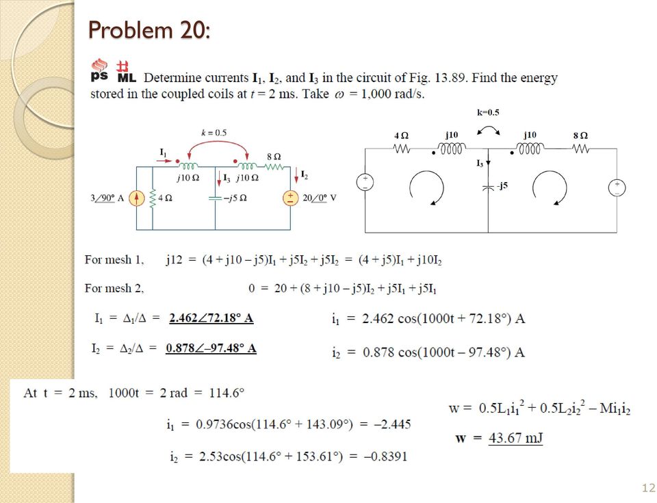
12 Problem 0:
13 3.4 inear Transformer Reflected Impedance 3 inear Transformer refers to a case where the inductances and and mutual inductance M are constant. V V ref in Z R Z R M R Z I V MI I I Z R MI I R I V ) ( ) ( ) ( ) ( ) (
")
14 3.4 inear Transformer Example 3 In the circuit below, calculate the input impedance and current I. Take Z =60-00Ω, Z =30+40Ω, and Z =80+60Ω. Ans: Zin ; I 0.53.A 4

15 3.4 inear and Ideal Transformer 5 Voltage Ratio (ignore resistances) Current Ratio In case of unity coupling (i.e., k =) and very large inductances, ) ( ) ( M Z MZ V V Z M I I Z Z V V I I
 ( ) ( M Z MZ V V Z M I I")

16 3.4 Ideal Transformer 6 The inductance is proportional to the number of turns squared. In case of an ideal Transformer, n N N an an Z Z V V n N N I I =0-3 N r /(8r+54l)

17 3.5 Ideal Transformer An ideal transformer is a unity-coupled, lossless transformer in which the primary and secondary coils have infinite selfinductances. V V N N n I N I N n (a) (b) Ideal Transformer Circuit symbol V>V step-up transformer V<V step-down transformer 7
 (b) Ideal Transformer Circuit symbol V>V")
18 3.5 Ideal Transformer Example 4 An ideal transformer is rated at 400/0V, 9.6 kva, and has 50 turns on the secondary side. Calculate: (a) the turns ratio, (b) the number of turns on the primary side, and (c) the current ratings for the primary and secondary windings. Ans: (a) (b) (c) This is a step-down transformer, n=0.05 N = 000 turns I = 4A and I = 80A 8

19 Problem 36 9

20 3.6 Applications Transformer as an isolation device to isolate ac supply from a rectifier 0


21 3.6 Applications Transformer as an isolation device to isolate dc between two amplifier stages.
22 3.6 Applications Transformer as a matching device Using an ideal transformer to match the speaker to the amplifier Equivalent circuit
23 3.6 Applications Example 5 Calculate the turns ratio of an ideal transformer required to match a 00Ω load to a source with internal impedance of.5kω. Find the load voltage when the source voltage is 30V. Ans: n = 0.; V = 3V 3

24 3.6 Practical Electric Utility transformers Used to step-up or step-down the voltage 4
25 Ideal Auto-Transformer Auto-transformers are used in cases where the voltage ratio is less than. Note that there is only one winding, the primary and secondary side share part of this winding. There is no electrical isolation between the primary and secondary sides. The apparent power rating of an auto-transformer is often much higher than a two-winding transformer of the same size (see example 3.0)
26 3-Phase Transformer
Coupled Inductors. Introducing Coupled Inductors
 Coupled Inductors From power distribution across large distances to radio transmissions, coupled inductors are used extensively in electrical applications. Their properties allow for increasing or decreasing
Transformer circuit calculations
 Transformer circuit calculations This worksheet and all related files are licensed under the Creative Commons Attribution License, version 1.0. To view a copy of this license, visit http://creativecommons.org/licenses/by/1.0/,
Chapter 11. Inductors ISU EE. C.Y. Lee
 Chapter 11 Inductors Objectives Describe the basic structure and characteristics of an inductor Discuss various types of inductors Analyze series inductors Analyze parallel inductors Analyze inductive
Module 22: Inductance and Magnetic Field Energy
 Module 22: Inductance and Magnetic Field Energy 1 Module 22: Outline Self Inductance Energy in Inductors Circuits with Inductors: RL Circuit 2 Faraday s Law of Induction dφ = B dt Changing magnetic flux
Outline. Systems and Signals 214 / 244 & Energy Systems 244 / 344. Ideal Inductor. Ideal Inductor (cont... )
") Outline Systems and Signals 214 / 244 & Energy Systems 244 / 344 Inductance, Leakage Inductance, Mutual Inductance & Transformers 1 Inductor revision Ideal Inductor Non-Ideal Inductor Dr. P.J. Randewijk
Outline Systems and Signals 214 / 244 & Energy Systems 244 / 344 Inductance, Leakage Inductance, Mutual Inductance & Transformers 1 Inductor revision Ideal Inductor Non-Ideal Inductor Dr. P.J. Randewijk
Circuits with inductors and alternating currents. Chapter 20 #45, 46, 47, 49
 Circuits with inductors and alternating currents Chapter 20 #45, 46, 47, 49 RL circuits Ch. 20 (last section) Symbol for inductor looks like a spring. An inductor is a circuit element that has a large
ES250: Electrical Science. HW7: Energy Storage Elements
 ES250: Electrical Science HW7: Energy Storage Elements Introduction This chapter introduces two more circuit elements, the capacitor and the inductor whose elements laws involve integration or differentiation;
Inductors & Inductance. Electronic Components
 Electronic Components Induction In 1824, Oersted discovered that current passing though a coil created a magnetic field capable of shifting a compass needle. Seven years later, Faraday and Henry discovered
Mutual Inductance and Transformers F3 3. r L = ω o
 utual Inductance and Transformers F3 1 utual Inductance & Transformers If a current, i 1, flows in a coil or circuit then it produces a magnetic field. Some of the magnetic flux may link a second coil
12. Transformers, Impedance Matching and Maximum Power Transfer
 1 1. Transformers, Impedance Matching and Maximum Power Transfer Introduction The transformer is a device that takes AC at one voltage and transforms it into another voltage either higher or lower than
The Flyback Converter
 The Flyback Converter Lecture notes ECEN4517! Derivation of the flyback converter: a transformer-isolated version of the buck-boost converter! Typical waveforms, and derivation of M(D) = V/! Flyback transformer
DC-DC Converter Basics
 Page 1 of 16 Free Downloads / Design Tips / Java Calculators / App. Notes / Tutorials / Newsletter / Discussion / Components Database / Library / Power Links / Software / Technical Articles / On-Line Textbook
2. A conductor of length 2m moves at 4m/s at 30 to a uniform magnetic field of 0.1T. Which one of the following gives the e.m.f. generated?
 Extra Questions - 2 1. A straight length of wire moves through a uniform magnetic field. The e.m.f. produced across the ends of the wire will be maximum if it moves: a) along the lines of magnetic flux
Coupling Magnetic Signals to a SQUID Amplifier
 SQUID Application Note 105-0 Coupling Magnetic Signals to a SQUID Amplifier Matching the effective inductances of the Pickup Coil and the Input Coil to detect and couple magnetic flux maximizes the sensitivity
Power supplies. EE328 Power Electronics Assoc. Prof. Dr. Mutlu BOZTEPE Ege University, Dept. of E&E
 Power supplies EE328 Power Electronics Assoc. Prof. Dr. Mutlu BOZTEPE Ege University, Dept. of E&E EE328 POWER ELECTRONICS Outline of lecture Introduction to power supplies Modelling a power transformer
EE301 Lesson 14 Reading: 10.1-10.4, 10.11-10.12, 11.1-11.4 and 11.11-11.13
 CAPACITORS AND INDUCTORS Learning Objectives EE301 Lesson 14 a. Define capacitance and state its symbol and unit of measurement. b. Predict the capacitance of a parallel plate capacitor. c. Analyze how
An equivalent circuit of a loop antenna.
 3.2.1. Circuit Modeling: Loop Impedance A loop antenna can be represented by a lumped circuit when its dimension is small with respect to a wavelength. In this representation, the circuit parameters (generally
Inductance. Motors. Generators
 Inductance Motors Generators Self-inductance Self-inductance occurs when the changing flux through a circuit arises from the circuit itself. As the current increases, the magnetic flux through a loop due
Lecture 24. Inductance and Switching Power Supplies (how your solar charger voltage converter works)
") Lecture 24 Inductance and Switching Power Supplies (how your solar charger voltage converter works) Copyright 2014 by Mark Horowitz 1 Roadmap: How Does This Work? 2 Processor Board 3 More Detailed Roadmap
Lecture 24 Inductance and Switching Power Supplies (how your solar charger voltage converter works) Copyright 2014 by Mark Horowitz 1 Roadmap: How Does This Work? 2 Processor Board 3 More Detailed Roadmap
AC Generators. Basic Generator
 AC Generators Basic Generator A basic generator consists of a magnetic field, an armature, slip rings, brushes and a resistive load. The magnetic field is usually an electromagnet. An armature is any number
Capacitors in Circuits
 apacitors in ircuits apacitors store energy in the electric field E field created by the stored charge In circuit apacitor may be absorbing energy Thus causes circuit current to be reduced Effectively
THE PER-UNIT SYSTEM. (2) The per-unit values for various components lie within a narrow range regardless of the equipment rating.
 The per-unit values for various components lie within a narrow range regardless of the equipment rating.") THE PER-UNIT SYSTEM An interconnected power system typically consists of many different voltage levels given a system containing several transformers and/or rotating machines. The per-unit system simplifies
THE PER-UNIT SYSTEM An interconnected power system typically consists of many different voltage levels given a system containing several transformers and/or rotating machines. The per-unit system simplifies
April 1. Physics 272. Spring 2014 http://www.phys.hawaii.edu/~philipvd/pvd_14_spring_272_uhm.html. Prof. Philip von Doetinchem philipvd@hawaii.
 Physics 272 April 1 Spring 2014 http://www.phys.hawaii.edu/~philipvd/pvd_14_spring_272_uhm.html Prof. Philip von Doetinchem philipvd@hawaii.edu Phys272 - Spring 14 - von Doetinchem - 164 Summary Gauss's
Eðlisfræði 2, vor 2007
 [ Assignment View ] [ Print ] Eðlisfræði 2, vor 2007 30. Inductance Assignment is due at 2:00am on Wednesday, March 14, 2007 Credit for problems submitted late will decrease to 0% after the deadline has
Chapter 6: Converter circuits
 Chapter 6. Converter Circuits 6.. Circuit manipulations 6.2. A short list of converters 6.3. Transformer isolation 6.4. Converter evaluation and design 6.5. Summary of key points Where do the boost, buck-boost,
12. The current in an inductor is changing at the rate of 100 A/s, and the inductor emf is 40 V. What is its self-inductance?
 12. The current in an inductor is changing at the rate of 100 A/s, and the inductor emf is 40 V. What is its self-inductance? From Equation 32-5, L = -E=(dI =dt) = 40 V=(100 A/s) = 0.4 H. 15. A cardboard
Single and Three Phase Transformer Testing Using Static Motor Circuit Analysis Techniques
 Single and Three Phase Transformer Testing Using Static Motor Circuit Analysis Techniques Howard W. Penrose, Ph.D On behalf of ALL-TEST Pro, LLC Old Saybrook, CT Introduction Field and shop testing of
WINDING RESISTANCE TESTING
 WINDING RESISTANCE TESTING WINDING RESISTANCE TEST SET, MODEL WRT-100 ADWEL INTERNATIONAL LTD. 60 Ironside Crescent, Unit 9 Scarborough, Ontario, Canada M1X 1G4 Telephone: (416) 321-1988 Fax: (416) 321-1991
First Year (Electrical & Electronics Engineering)
") Z PRACTICAL WORK BOOK For The Course EE-113 Basic Electrical Engineering For First Year (Electrical & Electronics Engineering) Name of Student: Class: Batch : Discipline: Class Roll No.: Examination Seat
Z PRACTICAL WORK BOOK For The Course EE-113 Basic Electrical Engineering For First Year (Electrical & Electronics Engineering) Name of Student: Class: Batch : Discipline: Class Roll No.: Examination Seat
Application Note on Transformers (AN-20-002)
") Application Note on Transformers (AN20002) 1 Introduction The purpose of this application note is to describe the fundamentals of RF and microwave transformers and to provide guidelines to users in selecting
Application Note on Transformers (AN20002) 1 Introduction The purpose of this application note is to describe the fundamentals of RF and microwave transformers and to provide guidelines to users in selecting
REPORT ON CANDIDATES WORK IN THE CARIBBEAN ADVANCED PROFICIENCY EXAMINATION MAY/JUNE 2008 ELECTRICAL AND ELECTRONIC TECHNOLOGY (TRINIDAD AND TOBAGO)
") CARIBBEAN EXAMINATIONS COUNCIL REPORT ON CANDIDATES WORK IN THE CARIBBEAN ADVANCED PROFICIENCY EXAMINATION MAY/JUNE 2008 ELECTRICAL AND ELECTRONIC TECHNOLOGY (TRINIDAD AND TOBAGO) Copyright 2008 Caribbean
CARIBBEAN EXAMINATIONS COUNCIL REPORT ON CANDIDATES WORK IN THE CARIBBEAN ADVANCED PROFICIENCY EXAMINATION MAY/JUNE 2008 ELECTRICAL AND ELECTRONIC TECHNOLOGY (TRINIDAD AND TOBAGO) Copyright 2008 Caribbean
Chapter 12: Three Phase Circuits
 Chapter 12: Three Phase Circuits 12.1 What Is a Three Phase Circuit? 12.2 Balance Three Phase Voltages 12.3 Balance Three Phase Y to Y Connection 12.4 Other Balance Three Phase Connections 12.5 Power in
Power measurement in balanced 3 phase circuits and power factor improvement. 1 Power in Single Phase Circuits. Experiment no 1
 Experiment no 1 Power measurement in balanced 3 phase circuits and power factor improvement 1 Power in Single Phase Circuits Let v = m cos(ωt) = cos(ωt) is the voltage applied to a R-L circuit and i =
HIGH FREQUENCY TRANSFORMER WITH TRANSFORMER SWITCHOVER
 OPTIMUM EFFICIENCY AND FLEXIBLE USE HIGH FREQUENCY TRANSFORMER WITH TRANSFORMER SWITCHOVER One of the many requirements of the modern inverter is a broad, coordinated input and MPP voltage range with a
Last time : energy storage elements capacitor.
 Last time : energy storage elements capacitor. Charge on plates Energy stored in the form of electric field Passive sign convention Vlt Voltage drop across real capacitor can not change abruptly because
Chapter 35 Alternating Current Circuits
 hapter 35 Alternating urrent ircuits ac-ircuits Phasor Diagrams Resistors, apacitors and nductors in ac-ircuits R ac-ircuits ac-ircuit power. Resonance Transformers ac ircuits Alternating currents and
Chapter 14: Inductor design
 Chapter 14 Inductor Design 14.1 Filter inductor design constraints 14.2 A step-by-step design procedure 14.3 Multiple-winding magnetics design using the K g method 14.4 Examples 14.5 Summary of key points
Direction of Induced Current
 Direction of Induced Current Bar magnet moves through coil Current induced in coil A S N v Reverse pole Induced current changes sign B N S v v Coil moves past fixed bar magnet Current induced in coil as
Line Reactors and AC Drives
 Line Reactors and AC Drives Rockwell Automation Mequon Wisconsin Quite often, line and load reactors are installed on AC drives without a solid understanding of why or what the positive and negative consequences
Edmund Li. Where is defined as the mutual inductance between and and has the SI units of Henries (H).
.") INDUCTANCE MUTUAL INDUCTANCE If we consider two neighbouring closed loops and with bounding surfaces respectively then a current through will create a magnetic field which will link with as the flux passes
INDUCTANCE MUTUAL INDUCTANCE If we consider two neighbouring closed loops and with bounding surfaces respectively then a current through will create a magnetic field which will link with as the flux passes
DHANALAKSHMI COLLEGE OF ENGINEERING DEPARTMENT OF ELECTRICAL AND ELECTRONICS ENGINEERING EE2302 - ELECTRICAL MACHINES II UNIT-I SYNCHRONOUS GENERATOR
 1 DHANALAKSHMI COLLEGE OF ENGINEERING DEPARTMENT OF ELECTRICAL AND ELECTRONICS ENGINEERING Constructional details Types of rotors EE2302 - ELECTRICAL MACHINES II UNIT-I SYNCHRONOUS GENERATOR PART A 1.
Slide 1 / 26. Inductance. 2011 by Bryan Pflueger
 Slide 1 / 26 Inductance 2011 by Bryan Pflueger Slide 2 / 26 Mutual Inductance If two coils of wire are placed near each other and have a current passing through them, they will each induce an emf on one
Diodes have an arrow showing the direction of the flow.
 The Big Idea Modern circuitry depends on much more than just resistors and capacitors. The circuits in your computer, cell phone, Ipod depend on circuit elements called diodes, inductors, transistors,
8 Speed control of Induction Machines
 8 Speed control of Induction Machines We have seen the speed torque characteristic of the machine. In the stable region of operation in the motoring mode, the curve is rather steep and goes from zero torque
Inductors. Resources and methods for learning about these subjects (list a few here, in preparation for your research):
:") Inductors This worksheet and all related files are licensed under the Creative Commons Attribution License, version 1.0. To view a copy of this license, visit http://creativecommons.org/licenses/by/1.0/,
Inductors This worksheet and all related files are licensed under the Creative Commons Attribution License, version 1.0. To view a copy of this license, visit http://creativecommons.org/licenses/by/1.0/,
EMI and t Layout Fundamentals for Switched-Mode Circuits
 v sg (t) (t) DT s V pp = n - 1 2 V pp V g n V T s t EE core insulation primary return secondary return Supplementary notes on EMI and t Layout Fundamentals for Switched-Mode Circuits secondary primary
Equipment: Power Supply, DAI, Transformer (8341), Variable resistance (8311), Variable inductance (8321), Variable capacitance (8331)
, Variable resistance (8311), Variable inductance (8321), Variable capacitance (8331)") Lab 5: Single-phase transformer operations. Objective: to examine the design of single-phase transformers; to study the voltage and current ratios of transformers; to study the voltage regulation of the
Lab 5: Single-phase transformer operations. Objective: to examine the design of single-phase transformers; to study the voltage and current ratios of transformers; to study the voltage regulation of the
Impedance Matching. Using transformers Using matching networks
 Impedance Matching The plasma industry uses process power over a wide range of frequencies: from DC to several gigahertz. A variety of methods are used to couple the process power into the plasma load,
d di Flux (B) Current (H)
 Current (H)") Comparison of Inductance Calculation Techniques Tony Morcos Magnequench Technology Center Research Triangle Park, North Carolina 1 VCM Baseline: Geometry Axially-magnetized MQ3-F 42 NdFeB disk Br = 131kG
Comparison of Inductance Calculation Techniques Tony Morcos Magnequench Technology Center Research Triangle Park, North Carolina 1 VCM Baseline: Geometry Axially-magnetized MQ3-F 42 NdFeB disk Br = 131kG
Homework #11 203-1-1721 Physics 2 for Students of Mechanical Engineering
 Homework #11 203-1-1721 Physics 2 for Students of Mechanical Engineering 2. A circular coil has a 10.3 cm radius and consists of 34 closely wound turns of wire. An externally produced magnetic field of
Application Note. So You Need to Measure Some Inductors?
 So You Need to Measure Some nductors? Take a look at the 1910 nductance Analyzer. Although specifically designed for production testing of inductors and coils, in addition to measuring inductance (L),
Chapter 30 Inductance
 Chapter 30 Inductance - Mutual Inductance - Self-Inductance and Inductors - Magnetic-Field Energy - The R- Circuit - The -C Circuit - The -R-C Series Circuit . Mutual Inductance - A changing current in
OPERATIONAL AMPLIFIERS. o/p
 OPERATIONAL AMPLIFIERS 1. If the input to the circuit of figure is a sine wave the output will be i/p o/p a. A half wave rectified sine wave b. A fullwave rectified sine wave c. A triangular wave d. A
Chapter 25 Alternating Currents
 Physics Including Human Applications 554 Chapter 25 Alternating Currents GOALS When you have mastered the contents of this chapter, you will be able to achieve the following goals: Definitions Define each
30. Bode Plots. Introduction
 0. Bode Plots Introduction Each of the circuits in this problem set is represented by a magnitude Bode plot. The network function provides a connection between the Bode plot and the circuit. To solve these
Objectives. Capacitors 262 CHAPTER 5 ENERGY
 Objectives Describe a capacitor. Explain how a capacitor stores energy. Define capacitance. Calculate the electrical energy stored in a capacitor. Describe an inductor. Explain how an inductor stores energy.
Chapter 12 Driven RLC Circuits
 hapter Driven ircuits. A Sources... -. A ircuits with a Source and One ircuit Element... -3.. Purely esistive oad... -3.. Purely Inductive oad... -6..3 Purely apacitive oad... -8.3 The Series ircuit...
Induced voltages and Inductance Faraday s Law
 Induced voltages and Inductance Faraday s Law concept #1, 4, 5, 8, 13 Problem # 1, 3, 4, 5, 6, 9, 10, 13, 15, 24, 23, 25, 31, 32a, 34, 37, 41, 43, 51, 61 Last chapter we saw that a current produces a magnetic
Unit/Standard Number. High School Graduation Years 2010, 2011 and 2012
 1 Secondary Task List 100 SAFETY 101 Demonstrate an understanding of State and School safety regulations. 102 Practice safety techniques for electronics work. 103 Demonstrate an understanding of proper
Step-up, step-down, and isolation transformers
 Step-up, step-down, and isolation transformers This worksheet and all related files are licensed under the Creative Commons Attribution License, version 1.0. To view a copy of this license, visit http://creativecommons.org/licenses/by/1.0/,
Lecture 22. Inductance. Magnetic Field Energy. Outline:
 Lecture 22. Inductance. Magnetic Field Energy. Outline: Self-induction and self-inductance. Inductance of a solenoid. The energy of a magnetic field. Alternative definition of inductance. Mutual Inductance.
Phasors. Phasors. by Prof. Dr. Osman SEVAİOĞLU Electrical and Electronics Engineering Department. ^ V cos (wt + θ) ^ V sin (wt + θ)
 ^ V sin (wt + θ)") V cos (wt θ) V sin (wt θ) by Prof. Dr. Osman SEVAİOĞLU Electrical and Electronics Engineering Department EE 209 Fundamentals of Electrical and Electronics Engineering, Prof. Dr. O. SEVAİOĞLU, Page 1 Vector
V cos (wt θ) V sin (wt θ) by Prof. Dr. Osman SEVAİOĞLU Electrical and Electronics Engineering Department EE 209 Fundamentals of Electrical and Electronics Engineering, Prof. Dr. O. SEVAİOĞLU, Page 1 Vector
Alternating-Current Circuits
 hapter 1 Alternating-urrent ircuits 1.1 A Sources... 1-1. Simple A circuits... 1-3 1..1 Purely esistive load... 1-3 1.. Purely Inductive oad... 1-5 1..3 Purely apacitive oad... 1-7 1.3 The Series ircuit...
Diode Applications. by Kenneth A. Kuhn Sept. 1, 2008. This note illustrates some common applications of diodes.
 by Kenneth A. Kuhn Sept. 1, 2008 This note illustrates some common applications of diodes. Power supply applications A common application for diodes is converting AC to DC. Although half-wave rectification
EE 1202 Experiment #4 Capacitors, Inductors, and Transient Circuits
 EE 1202 Experiment #4 Capacitors, Inductors, and Transient Circuits 1. Introduction and Goal: Exploring transient behavior due to inductors and capacitors in DC circuits; gaining experience with lab instruments.
= V peak 2 = 0.707V peak
 BASIC ELECTRONICS - RECTIFICATION AND FILTERING PURPOSE Suppose that you wanted to build a simple DC electronic power supply, which operated off of an AC input (e.g., something you might plug into a standard
Solution Derivations for Capa #11
 Solution Derivations for Capa #11 Caution: The symbol E is used interchangeably for energy and EMF. 1) DATA: V b = 5.0 V, = 155 Ω, L = 8.400 10 2 H. In the diagram above, what is the voltage across the
CHAPTER 30: Inductance, Electromagnetic Oscillations, and AC Circuits
 HAPTE 3: Inductance, Electromagnetic Oscillations, and A ircuits esponses to Questions. (a) For the maximum value of the mutual inductance, place the coils close together, face to face, on the same axis.
Product Data Bulletin
 Product Data Bulletin Power System Harmonics Causes and Effects of Variable Frequency Drives Relative to the IEEE 519-1992 Standard Raleigh, NC, U.S.A. INTRODUCTION This document describes power system
How To Understand And Understand The Theory Of Electricity
 DIRECT CURRENT AND ALTERNATING CURRENT SYSTEMS N. Rajkumar, Research Fellow, Energy Systems Group, City University Northampton Square, London EC1V 0HB, UK Keywords: Electrical energy, direct current, alternating
Current and Temperature Ratings
 Document 361-1 Current and Temperature Ratings Introduction This application note describes: How to interpret Coilcraft inductor current and temperature ratings Our current ratings measurement method and
Copyright 2011 Linear Technology. All rights reserved.
 Copyright. All rights reserved. LTspice IV Getting Started Guide 2 Benefits of Using LTspice IV Stable SPICE circuit simulation with Unlimited number of nodes Schematic/symbol editor Waveform viewer Library
G019.A (4/99) UNDERSTANDING COMMON MODE NOISE
 UNDERSTANDING COMMON MODE NOISE") UNDERSTANDING COMMON MODE NOISE PAGE 2 OF 7 TABLE OF CONTENTS 1 INTRODUCTION 2 DIFFERENTIAL MODE AND COMMON MODE SIGNALS 2.1 Differential Mode signals 2.2 Common Mode signals 3 DIFFERENTIAL AND COMMON
UNDERSTANDING COMMON MODE NOISE PAGE 2 OF 7 TABLE OF CONTENTS 1 INTRODUCTION 2 DIFFERENTIAL MODE AND COMMON MODE SIGNALS 2.1 Differential Mode signals 2.2 Common Mode signals 3 DIFFERENTIAL AND COMMON
W03 Analysis of DC Circuits. Yrd. Doç. Dr. Aytaç Gören
 W03 Analysis of DC Circuits Yrd. Doç. Dr. Aytaç Gören ELK 2018 - Contents W01 Basic Concepts in Electronics W02 AC to DC Conversion W03 Analysis of DC Circuits (self and condenser) W04 Transistors and
How To Understand A Transformer
 Audio Transformers by Bill Whitlock Jensen Transformers, Inc. 9304 Deering Avenue Chatsworth, CA 91311 This work first published by Focal Press in 2001 as Chapter 11 Handbook for Sound Engineers, Thi Edition
Let s examine the response of the circuit shown on Figure 1. The form of the source voltage Vs is shown on Figure 2. R. Figure 1.
 Examples of Transient and RL Circuits. The Series RLC Circuit Impulse response of Circuit. Let s examine the response of the circuit shown on Figure 1. The form of the source voltage Vs is shown on Figure.
Physics 2102 Lecture 19. Physics 2102
 Physics 2102 Jonathan Dowling Physics 2102 Lecture 19 Ch 30: Inductors and RL Circuits Nikolai Tesla What are we going to learn? A road map Electric charge Electric force on other electric charges Electric
HPS Universal. Single and Three Phase Potted. Buck-Boost Transformers. Buck-Boost Applications & Standard Specification... 80
 Buck-Boost Transformers Single and Three Phase Potted Buck-Boost Transformers Buck-Boost Applications & Standard Specification... 80 Selecting Buck-Boost Transformers... 81 Single Phase Selection Tables...
Understanding Delta Conversion Online "Power Regulation" - Part 2
 Application Note #40 Understanding Delta Conversion Online "Power Regulation" - Part 2 Introduction This application note is the second in a series on delta conversion theory of operation. For complete
DOE FUNDAMENTALS HANDBOOK ELECTRICAL SCIENCE Volume 3 of 4
 DOE-HDBK-1011/3-92 JUNE 1992 DOE FUNDAMENTALS HANDBOOK ELECTRICAL SCIENCE Volume 3 of 4 U.S. Department of Energy Washington, D.C. 20585 FSC-6910 Distribution Statement A. Approved for public release;
GUIDE FOR TESTING POWER TRANSFORMERS
 GUIDE FOR TESTING POWER TRANSFORMERS Routine test 11/11/02 Pagina 1 di 10 INDEX Introduction... 3 1 Dielectric tests Separate-source voltage withstand test... 4 2 Induced voltage test... 5 3 Voltage ratio
EET272 Worksheet Week 9
 EET272 Worksheet Week 9 answer questions 1-5 in preparation for discussion for the quiz on Monday. Finish the rest of the questions for discussion in class on Wednesday. Question 1 Questions AC s are becoming
Digital Energy ITI. Instrument Transformer Basic Technical Information and Application
 g Digital Energy ITI Instrument Transformer Basic Technical Information and Application Table of Contents DEFINITIONS AND FUNCTIONS CONSTRUCTION FEATURES MAGNETIC CIRCUITS RATING AND RATIO CURRENT TRANSFORMER
Chapter 3 AUTOMATIC VOLTAGE CONTROL
 Chapter 3 AUTOMATIC VOLTAGE CONTROL . INTRODUCTION TO EXCITATION SYSTEM The basic function of an excitation system is to provide necessary direct current to the field winding of the synchronous generator.
E.G.Strangas MSU Electrical Machines and Drives Laboratory
 Notes for an Introductory Course On Electrical Machines and Drives E.G.Strangas MSU Electrical Machines and Drives Laboratory Contents Preface ix 1 Three Phase Circuits and Power 1 1.1 Electric Power
Chapter 15: Transformer design
 Chapter 15 Transformer Design Some more advanced design issues, not considered in previous chapter: : n Inclusion of core loss + + Selection of operating flux i 1 density to optimize total loss v 1 v Multiple
Module Title: Electrotechnology for Mech L7
 CORK INSTITUTE OF TECHNOLOGY INSTITIÚID TEICNEOLAÍOCHTA CHORCAÍ Autumn Examinations 2012 Module Title: Electrotechnology for Mech L7 Module Code: ELEC7007 School: School of Mechanical, Electrical and Process
Current Transformers Ratio / Polarity / Types
 CT1 Current Ratio / Polarity / Types Application Current (CT s) are instrument transformers that are used to supply a reduced value of current to meters, protective relays, and other instruments. CT s
RC & RL Transient Response
 EE 2006 University of Minnesota Duluth ab 8 1. Introduction R & R Transient Response The student will analyze series R and R circuits. A step input will excite these respective circuits, producing a transient
High Intensify Interleaved Converter for Renewable Energy Resources
 High Intensify Interleaved Converter for Renewable Energy Resources K. Muthiah 1, S.Manivel 2, Gowthaman.N 3 1 PG Scholar, Jay Shriram Group of Institutions,Tirupur 2 Assistant Professor, Jay Shriram Group
PHASOR DIAGRAMS HANDS-ON RELAY SCHOOL WSU PULLMAN, WA. RON ALEXANDER - BPA
 PHASOR DIAGRAMS HANDS-ON RELAY SCHOOL WSU PULLMAN, WA. RON ALEXANDER - BPA What are phasors??? In normal practice, the phasor represents the rms maximum value of the positive half cycle of the sinusoid
EDEXCEL NATIONAL CERTIFICATE/DIPLOMA UNIT 5 - ELECTRICAL AND ELECTRONIC PRINCIPLES NQF LEVEL 3 OUTCOME 4 - ALTERNATING CURRENT
 EDEXCEL NATIONAL CERTIFICATE/DIPLOMA UNIT 5 - ELECTRICAL AND ELECTRONIC PRINCIPLES NQF LEVEL 3 OUTCOME 4 - ALTERNATING CURRENT 4 Understand single-phase alternating current (ac) theory Single phase AC
Transformer Calculations
 Transformer Calculations Transformers Transformers are one of the most basic yet practical devices used today. No matter where you are there is always a transformer nearby. They are used throughout alternating-current
Design Considerations for an LLC Resonant Converter
 Design Considerations for an LLC Resonant Converter Hangseok Choi Power Conversion Team www.fairchildsemi.com 1. Introduction Growing demand for higher power density and low profile in power converter
Motor Fundamentals. DC Motor
 Motor Fundamentals Before we can examine the function of a drive, we must understand the basic operation of the motor. It is used to convert the electrical energy, supplied by the controller, to mechanical
VOLTAGE REGULATOR AND PARALLEL OPERATION
 VOLTAGE REGULATOR AND PARALLEL OPERATION Generator sets are operated in parallel to improve fuel economy and reliability of the power supply. Economy is improved with multiple paralleled generators by
Unit 6 Transformers. Lead-in. Basic principles. Task 1. Task 2. What applications of transformers do you know?
 Unit 6 Transformers Lead-in What applications of transformers do you know? Basic principles Task 1 Match the words and phrases with the translations. 1. magnetic field 2. induced voltage 3. conductors
Current Ripple Factor of a Buck Converter
 Application Note Edwin Wang AN1 April 14 Current Ripple Factor of a Buck Converter Abstract Inductor and capacitor forms a low-pass filter in a buck converter. The corner frequency the C filter is always
Inductors. AC Theory. Module 3
 Module 3 AC Theory What you ll learn in Module 3. Section 3.1 Electromagnetic Induction. Magnetic Fields around Conductors. The Solenoid. Section 3.2 Inductance & Back e.m.f. The Unit of Inductance. Factors