3465 Diablo Avenue, Hayward, CA U.S.A Fax:
|
|
|
- Myra Beasley
- 8 years ago
- Views:
Transcription
1
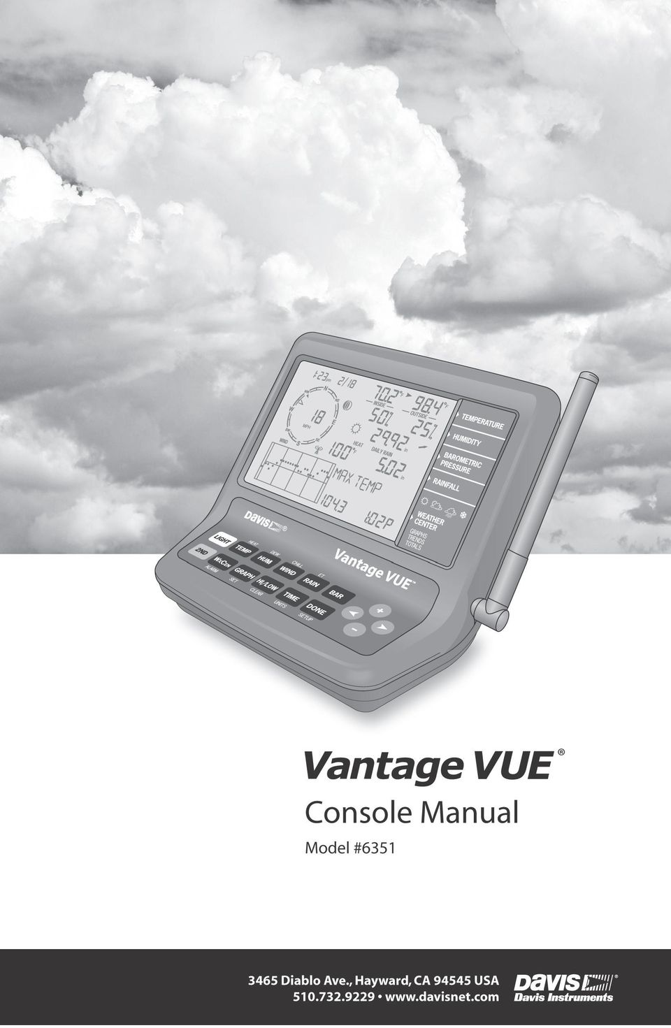
2 FCC Part 15 Class B Registration Warning This equipment has been tested and found to comply with the limits for a Class B digital device, pursuant to Part 15 of the FCC Rules. These limits are designed to provide reasonable protection against harmful interference in a residential installation. This equipment generates, uses, and can radiate radio frequency energy and, if not installed and used in accordance with the instructions, may cause harmful interference to radio communications. However, there is no guarantee that interference will not occur in a particular installation. If this equipment does cause harmful interference to radio or television reception, which can be determined by turning the equipment on and off, the user is encouraged to try to correct the interference by one or more of the following measures: Reorient or relocate the receiving antenna. Increase the separation between the equipment and receiver. Connect the equipment into an outlet on a circuit different from that to which the receiver is connected. Consult the dealer or an experienced radio/tv technician for help. Changes or modification not expressly approved in writing by Davis Instruments may void the warranty and void the user's authority to operate this equipment. FCC ID: IR2DWW6351 IC: 3788A-6351 EC EMC Compliance This product complies with the essential protection requirements of the EC EMC Directive 2004/108/EC; Low Voltage Directive 2006/95/EC; and Eco-Design Directive 2005/32/EC >0.5 watt no-load adaptor. RoHS Compliant Vantage Vue Console Manual Document Part Number: Rev. G, September 4, 2014 For Vantage Vue Consoles #6351 And Vantage Vue Weather Stations #6250, 6357 Vantage Vue and Vantage Pro2 are trademarks of Davis Instruments Corp., Hayward, CA. Davis Instruments Corp All rights reserved. Davis Instruments Quality Management System is ISO 9001 certified. Information in this document subject to change without notice Diablo Avenue, Hayward, CA U.S.A Fax: info@davisnet.com

3 Table of Contents Welcome to Vantage Vue...1 Console Features: Keyboard & Display... 1 In This Manual... 2 Vantage Vue System Installation Steps... 2 Installing the Console...3 Powering the Console... 3 Installing Batteries... 3 Installing the AC Power Adapter (Optional)... 4 Console Location... 4 Table & Shelf Placement... 5 Wall Mounting... 5 Using Your Weather Station...6 Console Modes... 6 Setup Mode... 6 Setup Mode Commands... 6 Screen 1: Time & Date... 7 Screen 2: Time Zone... 7 Screen 3: Daylight Saving Settings... 8 Screen 4: Daylight Saving Status... 8 Screen 5: Active Transmitters... 8 Screen 6: Configuring Transmitter IDs... 9 Screen 7: Retransmit Screens 8 and 9: Latitude and Longitude Screen 10: Elevation Screen 11: Barometric Reduction Setting Screen 12: Wind Cup Type (Optional) Screen 13: Rain Collector Screen 14: Rain Season Screens 15 and 16: Cooling and Heating Degree Day Base Screens 17 and 18: Commentary and Key Beep Screen 19: Baud Rate (Optional) Exiting Setup Mode Clear All Command Current Weather Mode Current Weather Mode Commands Displaying Weather Variables Time & Date, Sunrise & Sunset Time, Moon Phase, Forecast Icons Wind Speed and Direction Inside and Outside Temperature Humidity Barometric Pressure Pressure Trend Wind Chill i

4 Dew Point Heat Index Rain Evapotranspiration (ET) (Optional) Weather Center Light Selecting Units of Measure Calibrating, Setting, and Clearing Variables Calibrating Temperature and Humidity Calibrating Wind Direction Reading Calibrating Barometric Pressure Calibrating Rain Setting Weather Variables Clearing Weather Variables Accumulations & Calibrations Clear All Command Highs and Lows Mode Viewing Highs and Lows Alarm Mode Special Alarms Setting Alarms Setting the Time Alarm Clearing Alarm Settings Silencing Alarms Changing Alarm Sound Graph Mode Viewing Graphs Troubleshooting and Maintenance...36 Vantage Vue Troubleshooting Guide Troubleshooting Reception Problems Check Console Reception Console Diagnostic Mode Diagnostic Screen Commands Screen 1: Statistical Diagnostic Screen Screen 2: Reception Diagnostic Screen Console Maintenance Changing Batteries Console Firmware Versions One Year Limited Warranty Contacting Davis Technical Support Appendix A: Weather Data...42 Appendix B: Specifications...47 Appendix C: Wireless Repeater Configuration...51 ii

5 Chapter 1 Welcome to Vantage Vue The console of your new Vantage Vue wireless weather station displays and records your station s weather data, provides graph and alarm functions, and interfaces to a computer using our optional WeatherLink software. Your Vantage Vue station also includes an outdoor Integrated Sensor Suite (ISS) that transmits outside sensor data to the console via a low-power radio. The console displays all the information coming from the ISS in an easy-to-use format. It can also receive data from a Davis Vantage Pro2 weather station. The Vantage Vue Quick Reference Guide included with your station provides an easy-to-use reference for most console functions. Console Features: Keyboard & Display HEAT DEW CHILL ET LIGHT TEMP HUM WIND RAIN BAR 2ND WXCEN GRAPH HI/LOW TIME DONE ALARM SET CLEAR UNITS SETUP Vantage Vue Keyboard Use the keyboard to access and scroll through current and historical data for individual variables, set and clear alarms, enter calibration values, set up and view graphs, and view detailed weather information available for each variable. The keyboard consists of 12 command keys and four navigation keys. A weather variable or console command is printed on each command key. Just press a key to select the variable or function printed on that key. Each command key also has a secondary function which is printed above the first row of keys or below the second row of keys. To select the secondary function, press and release 2ND and then immediately press the key for that function. HEAT TEMP 2ND After pressing 2ND, the 2nd icon displays above the moon phase icon on the screen indicating that all secondary key functions are enabled. Keys resume normal operation after the icon disappears (about 7-8 seconds). The + and - navigation keys along with the < and > navigation keys are used to select command options, adjust values, and to provide additional functions when used in combination with a command key. An arrow appears next to the variable selected in the display. 1

6 Console Features: Keyboard & Display In Current Weather Mode, the display shows the time and date, the likely forecast within the next 12 hours, current moon phase, and weather information for up to 8 different weather variables at a time. It also displays additional information pertinent to a selected variable in the Weather Center in the bottom right section of the console screen. Time & Date Sunrise/Sunset Arrow shows which variable is selected Inside & Outside Temperature Moon phase, alarm, & forecast icons Wind Compass Rose Antenna icon shows active transmission W NW SW WIND am N S NE SE E CHILL INSIDE F F F OUTSIDE in RAIN RATE in/hr Inside & Outside Humidity Barometric Pressure & Trend Rain data & ET* Wind Chill/Heat Index/Dew Point Graph of selected variable Weather Center with additional information In This Manual *ET, optional, available only when used with a Vantage Pro2 Plus or a Vantage Pro2 with Solar Radiation sensor. This manual contains all the information you will need to power, set up, and use your console. It also includes a troubleshooting section for solving some basic console issues. See Installing the Console on page 3 for information on powering and placing or mounting your Vantage Vue console. See Setup Mode on page 6 for information on configuring and setting up your console. See Current Weather Mode on page 15 for information on displaying current weather information. See Troubleshooting and Maintenance on page 36 for information on troubleshooting console issues and routine maintenance. Vantage Vue System Installation Steps Prepare the Integrated Sensor Suite (ISS) for Installation. See your Vantage Vue Integrated Sensor Suite Installation Manual. Install, power and set up the console Mount the ISS 2

7 Chapter 2 Installing the Console The Vantage Vue console is designed to give extremely accurate readings. As with any precision instrument, use care in its assembly and handling. Although installing the console is relatively simple, following the steps outlined in this chapter and assembling the Vantage Vue correctly from the start will help ensure that you enjoy all of its features with a minimum of time and effort. Powering the Console The Vantage Vue console does not require the use of an AC adapter. You may use the included adapter if you wish, but three C-cell batteries (not included) should power a wireless console for up to nine months. You can use either of these or both together, with the batteries providing backup power for the adapter. The console will display messages if any of your system s batteries are low. LOW CONSOLE BATTERIES: Replace the console batteries LOW BATTERY TRANSMITTER (ID#): Replace the battery in your outdoor Integrated Sensor Suite (ISS) or any optional transmitting station you may have added. Installing Batteries 1. Remove the battery cover located on the back of the console by pressing down on the two latches at the top of the cover. Installing batteries into the Vantage Vue 2. Insert three C batteries into the battery channels as shown. 3. Place the battery cover back onto the console and click it closed. 4. Check to make sure the console runs through a brief self-test procedure successfully. On power up, the console displays all the LCD segments and beeps three times (four times if you have a data logger plugged in). A message displays at the bottom of the console, followed by the first screen of Setup Mode. Press DONE to skip the message and enter into Setup Mode. Setup Mode guides you through steps required to configure the station. See Setup Mode on page 6 for more information. The console does not recharge the batteries. Because of this, and because NiCad batteries do not power the console as long as alkaline batteries, we do not recommend using NiCad batteries. 3
 should power a wireless console for up to nine months.")
8 Console Location Installing the AC Power Adapter (Optional) 1. Find the power jack located on the left side of the console case. 2. Insert the power adapter plug into the console power jack, then plug the other end of the adapter into an appropriate power outlet. 3. Check to make sure the console runs through a brief self-test procedure successfully. See Installing Batteries on page 3 for information on the self-test procedure. Plugging in the AC adapter When using an AC power adapter, be sure to use the power adapter supplied with your Vantage Vue console. Your console may be damaged by connecting the wrong power adapter. You must use AC power when using WeatherLinkIP. Console Location Place the console in a location where the keyboard is easily accessible and the display is easy to read. For more accurate readings, follow these suggestions. Avoid placing the console in direct sunlight. This may cause erroneous inside temperature and humidity readings and may damage the unit. Avoid placing the console near radiators or heating/air conditioning ducts. If you are mounting the console on a wall, choose an interior wall. Avoid exterior walls that tend to heat up or cool down depending on the weather. Avoid positioning a wireless console near large metallic appliances such as refrigerators, televisions, heaters, or air conditioners. The console antenna does not rotate in a complete circle. Avoid forcing the console antenna when rotating it. Be aware of possible interference from cordless phones or other devices. To prevent interference, maintain a distance of 10 feet (3 meters) between the Vantage Vue console and a cordless phone (handset and base). 4

9 Console Location Table & Shelf Placement The console comes with a kickstand so that the console can be displayed on any flat surface. To install the kickstand: 1. Locate the two keyholes on the back of the console. 2. Place the two round tabs on the kickstand into the to keyholes and slide the kickstand up into place. Securing the kickstand 3. Install the two round rubber feet on the bottom of the console. 4. Install the two rubber channel feet on the kickstand. Installing the rubber feet Wall Mounting The console mounts to the wall using two keyholes located on the back of the case (the same two keyholes are used to hold the console kickstand in place) and two #6 x 1'' pan head self-threading screws included in the hardware kit. To mount the console on a wall: 1. Use a ruler to mark two mounting hole positions on the wall 4 15 / 16 '' inches (125 mm) apart. Use the guide holes on the kickstand as a template for the keyhole spacing. 2. Use a drill and a 3 / 32 or 7 / 64 '' (2.4 or 2.8 mm) drill bit to drill two pilot holes for the screws. 3. Using a screwdriver, drive the two #6 x 1'' pan head self-threading screws into the wall. Leave at least 1 / 8 '' (3 mm) between the wall and the heads of the screws. Mounting the console on a wall 4. Guide the two keyholes on the back of the console over the two screws. 5
 and")
10 Setup Mode Chapter 3 Using Your Weather Station The console LCD screen and keyboard provide easy access to your weather information. The LCD display shows current and past weather conditions as well as a forecast of future conditions. The keyboard controls console functions for viewing current and historical weather information, setting and clearing alarms, viewing and/or changing station settings, setting up and viewing graphs, and more. Console Modes The Vantage Vue console operates in five different modes: Setup Mode Current Weather High/Low Alarm Graph Description Use Setup Mode to enter the time, date, and other information required to calculate and display weather data such as latitude, longitude and elevation. See Setup Mode on this page. Use Current Weather Mode to see current weather information, change measurement units, and to set, clear or calibrate weather readings. See Current Weather Mode on page 15. Use High/Low Mode to display the daily, monthly or yearly high and low readings. See Highs and Lows Mode on page 30. Use Alarm Mode to set, clear, and review alarm settings for up to 30 different variables/settings. See Alarm Mode on page 31. Use Graph Mode to display your weather data in the graph section of the console for the current and last 25 time intervals (hours, days, months or even years) in over 50 different graphs. See Graph Mode on page 33. When the console is first powered, or repowered, the Time & Date screen appears. If nothing is done for 10 minutes, the screen will time out and go to the Current Weather screen. (This is true for any setup screen except for the Active Transmitters screen.) Setup Mode Setup Mode provides access to the station configuration settings that control how the station operates. Setup Mode consists of a series of screens for selecting console and weather station configuration options. Setup Mode Commands Setup Mode displays when the console is first powered. This mode can be displayed at any time to change any of the console options. Use the following commands to enter, exit and navigate Setup Mode: Enter Setup Mode by pressing and releasing 2ND and then SETUP. 2ND DONE Press DONE to move to the next screen in the Setup Mode. SETUP DONE 6

11 Setup Mode Press BAR to display the previous screen in the Setup Mode. Press the < and > keys to move to the different segments and options in the Setup Mode screens. Press the + and - keys to scroll through the different options available. BAR Press 2ND and UNITS to change units of measure when applicable. Exit Setup Mode by pressing and holding DONE until the Current 2ND TIME UNITS Weather screen displays. See Current Weather Mode on page 15 for more information. Screen 1: Time & Date The very first time you power the console, you should enter the correct date and local time. To change the time and date: am 1. Press the < and > keys to select the hour, minute, month, day or year segments. The selected time or date setting blinks on and off. YEAR 2. Press the + and - keys to adjust a value up or down. To choose between a 12-hour or 24-hour clock, first select either the hour or minute setting, then press 2ND and immediately press UNITS. This toggles the clock setting between the two clock types. Screen 1: Time & Date To choose between a MM/DD or DD.MM display for the date, first select either the day or month setting, then press 2ND and immediately press UNITS. This switches the console from one date display to the other. 3. Press DONE to move to the next screen. Whenever the console is repowered after power is off or lost, it will open to this screen. This allows you to enter the correct time if needed. If nothing is done after 10 minutes, the screen will time-out and go to the Current Weather screen. Screen 2: Time Zone The console is pre-programmed with a combination of US time zones and the names of major cities representing time zones around the world. You can also configure your time zone using the Universal Time Coordinate (UTC, also known as Greenwich Mean Time or GMT) offset. UTC offset measures the difference between the time in any time zone and a standard time, set by convention as the time at the Royal Observatory in Greenwich, England. Hayward, California, the home of Davis Instruments, observes Pacific Standard Time. The UTC offset for Pacific Standard Time is -8:00, or eight hours behind Universal Time (UTC). When daylight saving time is observed, an hour is added to the offset time automatically. Use this function in correlation with Screen 3: Daylight Saving Settings on page 8. 7

12 Setup Mode 1. Press the + and - keys to cycle through time zones. 2. If your time zone is not shown, press 2ND then press the + and - keys to set your UTC offset (UTC offset uses 15 minute increments). 3. Press DONE to select the time zone or UTC offset shown on the screen and move to the next screen. Screen 3: Daylight Saving Settings In most of the United States and Canada (except Saskatchewan, Arizona, and Hawaii) and Europe you should use the AUTO Daylight Saving setting. The console is pre-programmed to use the correct starting and stopping dates for daylight saving time in these areas, based on the time zone setting in Screen 2: Time Zone. Weather stations located outside the United States, Canada, and Europe, or in areas that do not observe daylight saving time should use the MANUAL setting. 1. Press the + and - keys to choose Auto or Manual. 2. Press DONE to move to the next screen. Screen 4: Daylight Saving Status Use this screen to either verify the correct automatic daylight saving status or to set daylight saving manually. 1. If the daylight saving setting is MANUAL, press the + and - keys to turn daylight saving time on or off on the appropriate days of the year. This will advance the time by one hour. (Similarly, if you turn daylight saving time off, the time will be set back one hour.) If you have an AUTO daylight saving setting, the console displays the appropriate setting based on the current time and date. 2. Press DONE to move to the next screen. Screen 5: Active Transmitters Screen 5 displays the message Receiving from... and shows the ID number of any transmitters being received by the console. The rest of the screen is blank. If your ISS uses the factory settings and your console is receiving the signal, the screen displays RECEIVING FROM 1. The antenna icon displays if any station s signal has been received. The antenna icon will not display if the console has not received a signal from a station. If you have installed a Vantage Pro2 ISS or Anemometer Transmitter kit, or if a nearby neighbor has a Davis weather station, or if you are receiving from another console in retransmit mode, its ID number will also be displayed. 8
 and Europe you should use the AUTO Daylight Saving setting.")
13 Setup Mode A Vantage Vue or Vantage Pro2 ISS or a Vantage Pro2 Anemometer Transmitter Kit must be powered for the console to recognize it. Refer to the Integrated Sensor Suite Installation Manual or other station manual for more information. It may take several minutes for the console to acquire and display a transmitter ID after power is applied to both units. 1. Make a note of the station number(s) listed on the screen. 2. Press DONE to move to the next screen. Screen 6: Configuring Transmitter IDs Setup Screen 6 allows you to change the ISS transmitter ID and to add or remove optional transmitter stations. The default transmitter ID setting is 1 VUE ISS (refers to a Vantage Vue ISS), which is appropriate for most installations. If you are using only the Vantage Vue ISS with ID 1 press DONE to move to the next screen. Typically, you can use the default transmitter ID setting of 1 unless a nearby neighbor has a Vantage Pro2 or Vantage Vue station that uses transmitter ID 1. If you wish to change this default transmitter ID: 1. Press the < and > keys to select a transmitter ID. When you select a transmitter ID (1-8), the ID number is displayed on the screen as well as its current configuration (OFF, VUE ISS, VP2 ISS or WIND). 2. Press the + or - keys to toggle console reception of signals from transmitters using that ID on and off. Make sure any unused ID numbers are set to OFF. To change the station type for the transmitter ID: 1. Press GRAPH to change the type of station assigned from VUE ISS to VP2 ISS or WIND. VUE ISS - Refers to the Vantage Vue ISS (whether direct transmission or retransmission from another console). VP2 ISS - Refers to the Vantage Pro2 ISS (whether direct transmission or retransmission from another console). WIND - Refers to an optional Anemometer Transmitter Kit (direct transmission only). 2. Press DONE to move to the next screen. This screen contains functionality for enabling repeaters. If the word Repeater displays in the right corner of the screen and you are not using repeaters as part of your network, see Clearing Repeater ID on page 51. If you are using repeaters as part of your network see Wireless Repeater Configuration (Appendix C) on page 51. 9

14 Setup Mode Screen 7: Retransmit The console can take data it receives from all three station types and retransmit it to other Vantage Vue or Vantage Pro2 consoles using the retransmit feature. By toggling the feature on, the console becomes another transmitter that requires its own unique ID to transmit the data received from the ISS. 1. Press the + or - key to turn the retransmit function on and off. The first available transmitter ID not assigned to a station in Screen 6: Configuring Transmitter IDs will be assigned to the console. Make sure no other wireless Davis weather station is transmitting on the same ID. The Vantage Vue console can only retransmit data from either a Vantage Vue ISS or console; or a Vantage Pro2 ISS or console. Data from other stations will not retransmit. When retransmit has already been enabled, pressing the < or > keys changes the transmitter ID used for retransmit. 2. Use the > key to scroll through the list of available transmitter IDs and select the ID for your console. 3. Press DONE to move to the next screen. Make a note of the ID selected for retransmit and the transmitter type (ISS or VP2) the console is retransmitting. Make sure the console that is receiving the retransmitted data is configured to the correct transmitter type. See Screen 6: Configuring Transmitter IDs on page 9 for more information. Screens 8 and 9: Latitude and Longitude The console uses latitude and longitude to determine your location, allowing it to adjust the forecast and calculate the times for sunset and sunrise. Latitude measures distance north or south of the equator. Longitude measures distance east or west of the Prime Meridian, an imaginary line running north and south through Greenwich, England. If you do not know your latitude and longitude, there are several ways to find out. Many atlases and maps include latitude and longitude lines. You can also talk to the reference department of your local library, call your local airport, or search on the Internet. An easy way to find your latitude and longitude is to download Google Earth ( The more accurate you are, the better; however, a reasonable estimate will work, too. 1. Press the < and > keys to move between fields. 2. Press the + and - keys to change the settings up or down. 3. Press 2ND and then UNITS to select between SOUTH or NORTH. 4. Press DONE to move to the Longitude screen. 10

15 Setup Mode 1. Press the < and > keys to move between fields. 2. Press the + and - keys to change the settings up or down. 3. To select EAST or WEST, press 2ND, then UNITS. 4. Press DONE to move to the next screen. Screen 10: Elevation Your station s elevation is used in determining your barometric pressure. Meteorologists standardize barometric pressure data to sea level so that surface readings are comparable, whether they are taken on a mountainside or by the ocean. To use this same standardization and ensure consistent readings, enter your elevation in this screen. If you do not know your elevation, there are several ways to find out. Many atlases and almanacs include elevation for cities and towns. You can also check with the reference department of your local library, or use Google Maps (in terrain view). The more accurate you are, the better; but a reasonable estimate works too. 1. Press the < and > keys to move from one value to another. 2. Press the + and - keys to adjust a numeral up or down. 3. To switch between feet and meters, press 2ND then press UNITS. 4. If your location is below sea level, such as in Death Valley or the Salton Sea, first enter the elevation as a positive number. Select the 0 immediately to the left of the left-most nonzero digit (the second zero from the left in 0026, for example, or the first zero from the left in 0207) and press and hold the + or - key until it cycles from 0 to 9 and then -. You can only set the elevation to negative after you have entered a non-zero digit and when the zero in the position immediately to the left of the left-most non-zero digit has been selected. If you need to enter an elevation below -999 feet, select meters and enter the converted number (multiply your elevation in feet by ). 5. Press DONE to move to the next screen. 11

16 Setup Mode Screen 11: Barometric Reduction Setting The Barometric Reduction Setting screen indicates the method by which barometric pressure is to be determined and calculated. The factory default is NOAA, but in this screen you may select a different method. To change the barometric reduction setting: 1. Press + or - to change the barometer reduction setting type: NOAA (Default Setting) The barometer is reduced to sea level using a technique that factors in the humidity and temperature of the column of air. ALT SETTING (Altimeter Setting) The barometer is reduced to sea level using a standard column of air, often referred to as a standard atmosphere. NONE Reports a raw barometric pressure reading unadjusted for elevation/altitude. 2. Press DONE to move to the next screen. See Calibrating Barometric Pressure on page 28 to learn how to fine-tune your barometric pressure to a local source. Screen 12: Wind Cup Type (Optional) The Wind Cup Type screen displays if you selected VP2 or WIND in Screen 6 of the Setup Mode. This screen does not display if you have selected a Vantage Vue ISS. See Screen 6: Configuring Transmitter IDs on page 9 for more information. The Wind Cup Type screen contains three options: LARGE, SMALL, or OTHER. In most Vantage Pro2 anemometer or ISS Installations, LARGE is the cup type that is shipped with all Vantage Pro2 anemometers. See the Vantage Pro2 Console Manual for more information. To change the wind cup type: 1. Press the + and - keys to scroll through the three wind cup options. 2. Press DONE to use the selected setting and move to the next screen. Do not change the wind cup type from LARGE if you are using the wind cups that were shipped with your system. Screen 13: Rain Collector The tipping spoon in the Vantage Vue rain collector has been calibrated at the factory to measure either 0.01'' or 0.2mm of rain with each tip depending on the model. This screen is used at the factory for this calibration. The typical user will not need to change it and can skip this screen. in This screen will not change the units on your display. To change the units on your display from inches to mm, or vice versa, see Selecting Units of Measure on page
 The barometer is reduced to sea level using a standard column of air, often referred to as a standard atmosphere.")
17 Screen 14: Rain Season Setup Mode Because rainy seasons begin and end at different times in different parts of the world, you must specify the month you wish your yearly rain data to begin. January 1 st is the default setting. The date the rain season begins affects yearly rain rate highs and lows as well as the yearly rain totals. 1. Press the + and - keys to select the month for the start of the rainy season. 2. Press DONE to move to the next screen. This setting determines when the yearly rain total is reset to zero. Davis Instruments recommends a January rain season setting (the default), unless you reside on the west coast of the United States, the Mediterranean Coast, or experience dry winters in the southern hemisphere. If so, change the rain season setting to July 1 st. If you are performing hydrology studies in any of these climates in the Northern Hemisphere, change the rain season setting to October 1 st. Screens 15 and 16: Cooling and Heating Degree Day Base The Cooling and Heating Degree Day Base screens let you determine the temperature base that is used to calculate the number of cooling or heating degree days. A cooling degree day is used to determine the amount of energy or fuel used to keep a structure like your home or business cool. A heating degree day is used to determine the amount of energy or fuel used to keep a structure like your home or business warm. One cooling degree/day is the amount of cooling required to keep a structure cool when the outside temperature remains 1 F above the 65 F threshold for 24 hours. One cooling degree/ day is also the amount of cooling required when the temperature remains 24 F above the 65 F threshold for one hour. One heating degree/day is the amount of heat required to keep a structure warm when the outside temperature remains 1 F below the 65 F threshold for 24 hours. One heating degree/ day is also the amount of heat required when the temperature remains 24 F below the 65 F threshold for one hour. The cooling and heating degree days (similar to growing degree days and chilling requirement in agriculture) are used for agricultural purposes, as well as for energy use analysis. Our optional WeatherLink software (#6510USB, 6510SER, 6555) calculates degree day totals. Our optional Agricultural/Turf Management Software Module (#6511) adds the special reporting features to the WeatherLink software that include evapotranspiration and chilling requirement. The Cooling and Heating Degree Day Bases are used to determine the Cooling Degree Day Daily Total and Heating Degree Day Daily Total, which display as part of the Weather Center when the outside temperature variable is selected. See Inside and Outside Temperature on page 18 for more information. A base setting for both the Cooling and Heating Degree Day temperature is not set at the factory, allowing you to choose. A base of 65 F (15 C in Europe) is suitable for most applications. 13
, unless you reside on the west coast of the United States, the Mediterranean Coast, or experience dry winters in the southern")
18 Setup Mode To set your cooling degree day base: 1. Press 2ND and SET. The value of 65 appears. Use the < and > keys to select a segment of the value. 2. Press the + and - keys to adjust the value of the selected segment. 3. Press 2ND and UNITS to change the temperature setting between Fahrenheit and Celsius. 4. Press DONE to move to the next screen. The Heating Degree Day Base displays: To set your heating degree day base, follow steps 1 through 4 above. To turn the degree day function off, press 2ND and then clear. The value changes to dashes. F F If a base temperature is displayed, degree day data is being accumulated. If the value shows dashes, the degree day function is off and will not appear in the Weather Center. Screens 17 and 18: Commentary and Key Beep Commentary refers to the extra information and comments on current weather conditions, such as lunar and solar eclipses, meteor showers and other information, that displays on the console in the Weather Center. Key Beep is a sound that indicates a key has been pressed. (It is different from the error sound. To change this sound, See Changing Alarm Sound on page 33.) These functions can be turned off or on. 1. Press the + and - keys to toggle the setting to OFF or ON. 2. Adjust key beep volume using the < and > keys. 3. Press DONE to move to the next screen. Screen 19: Baud Rate (Optional) The Baud Rate screen displays only if a WeatherLink data logger is installed in the console. The console uses a serial, USB, or Ethernet port to communicate with a computer. If you are connecting the console directly to your computer via USB or Ethernet connection, leave the setting at 19200, the highest rate for the port. The baud rate setting on your console must match the baud rate setting in the software on your computer. If you are using WeatherLink for Vantage Vue, refer to WeatherLink Help for instructions on setting the serial port baud rate on your computer. 14

19 Current Weather Mode 1. Press the + and - keys to select the baud rate. Your Vantage Vue console supports baud rates of 1200, 2400, 4800, 9600, 14400, and Press DONE to save the baud rate settings. Exiting Setup Mode You have successfully completed all the screens in the Setup Mode. To exit Setup Mode, press and hold DONE for several seconds until the Current Weather screen appears. Clear All Command After you have completed the above set up procedures and have exited the Setup Mode and once the Vantage Vue ISS, Vantage Pro2 ISS or Anemometer Transmitter kit has been installed, use the Clear All command before putting your weather station into service. The Clear All command clears all stored high and low weather data including monthly and yearly highs and lows, and clears the alarm settings. The command is recommended to properly clear the console of any erroneous data when first putting your station into use. 1. Press WIND to display wind speed on the console. 2. Press 2ND, then press and hold CLEAR for at least six seconds. 3. Release CLEAR when you see CLEARING NOW displayed at the bottom of the console s screen. Current Weather Mode In the Current Weather Mode you can display the current data readings from your station, select units of measure, and calibrate, set, or clear weather variables. You can see up to eight weather variables on the screen at the same time, as well as the time and date, moon phase and forecast icons, and a graph of the currently selected variable. Some variables are always visible on the console screen while most variables share their location with one or more variables. You can select any variable not currently on the screen to display it. W NW SW WIND am N S NE SE E CHILL INSIDE F F RAIN RATE OUTSIDE in in/hr F 15

20 Displaying Weather Variables Current Weather Mode Commands Select a weather variable to display its data on the screen if it isn t already visible, or to graph the data available for that variable. Weather variables are selected via the console command keys: If the variable is printed on a key, press the key to select the variable. TEMP HUM WIND RAIN BAR The same field can display multiple values for each variable. Press the variable key to scroll through all the values Multiple variables may share the same field on the display. SW MPH SE CHILL F RAIN RATE WIND S in/hr DEW HEAT F F Wind chill, dew point, heat index share the same field in Current Weather Mode If a variable is printed above or below a key, first press and release 2ND, then quickly press the key below the printed variable to select that variable. HEAT DEW CHILL ET 2ND LIGHT 2ND TEMP HUM WIND RAIN BAR WXCEN GRAPH HI/LOW TIME DONE ALARM SET CLEAR UNITS SETUP After pressing 2ND, the 2nd icon displays on the screen for eight seconds. Key secondary functions are enabled during this time. The keys return to normal operation after the icon disappears. Select a variable and press WxCEN to display information pertinent to the selected variable in the Weather Center. Continue to press WxCEN to scroll through all the information available for the variable. You can also select any variable currently displayed on the LCD screen using the navigation keys. Press the + key to move the selection arrow up the screen. Press the - key to move it down the screen. Push the < key to move it left and push the > key to move it right. Displaying Weather Variables 2ND WXCEN The variables are arranged below in the order they are viewed on the console screen; left to right, top to bottom, starting with Time and Date. 16

21 Displaying Weather Variables Time and Date, Sunrise and Sunset Time, Moon Phase, Forecast Icons The time and date display in the upper left hand corner of the console screen, above the wind compass rose. Press TIME to display the sunrise and sunset time for the current day. Press TIME again to redisplay the time and date. TIME The phase of the moon is described in the am F F pm Weather Center section of the console when the Sunrise Sunset N INSIDE OUTSIDE NW NE sunrise and sunset times are displayed. The moon phase icon corresponds to the moon phase W E in MPH DEW RAIN DAY description in the Weather Center. See Moon SW SE F S in Phases on page 42. WIND The current forecast icon displays underneath the current moon phase icon. The forecast icons show what weather conditions may occur within the Sunrise and sunset times, moon phase and forecast icons, with the moon next 12 hours. See Forecast on page 43 for phase listed in the Weather Center more information on the forecast icons and descriptions of the forecasted weather they represent. See Screen 1: Time & Date on page 7 to change the console time and date or to select a 12- or 24-hour clock. Wind Speed and Direction Wind speed and direction are displayed in the compass rose in the upper left section of the console screen: am F F N INSIDE OUTSIDE NW NE W E mb SW MPH SE CHILL F RAIN RATE WIND S in/hr Wind speed, direction and wind information displayed in the Weather Center 1. Press WIND to select wind speed. Wind speed may be displayed in miles per hour (MPH), kilometers per hour (km/h), meters per second (m/s), or knots. See Selecting Units of Measure on page 26 for more information on changing the unit of measure. The graph will show the current and last 25 hours of readings. WIND 17
22 Displaying Weather Variables A solid arrow within the compass rose indicates the current wind direction. Open arrows indicate up to six different 10-minute dominant wind directions to provide a history of the dominant wind directions for the past hour. 2. Press WIND a second time to display the wind direction in degrees instead of the wind speed. Each additional WIND key press toggles the display between wind speed and wind direction in degrees. When displayed in degrees, due north displays as NW 360 N 45 NE If the solar panel on your ISS is not facing due south, you should recalibrate the wind direction reading on your console. See Calibrating Wind Direction Reading on page Press WxCEN to display the weather information available for wind in the Weather Center. 4. Press WxCEN multiple times to scroll through all the wind-related Weather Center screens, which include: Maximum Wind Speed Displays the highest wind speed recorded for the day. Includes the time the speed was recorded. Last 10 Minute Gust Displays the high wind gust in the last 10 minutes with the direction of the highest gust displayed in degrees. Average Wind Speed Displays the average speed over the past two minutes and over the past ten minutes. Beaufort Scale Toggles between a description of the wind speed and how the wind ranks on the Beaufort Scale. (See Beaufort Scale on page 44 for more information.) Wind Direction Displays the current wind direction in degrees. Inside and Outside Temperature Inside and outside temperature are displayed in the top right portion on the console screen. The inside temperature is located above the word INSIDE and the outside temperature is located above the word OUTSIDE. W NW SW WIND pm N MPH S NE SE E 270 W CHILL 225 SW INSIDE F 180 S F RAIN RATE 90 E 135 SE OUTSIDE mb in/hr F Inside and outside temperature with information displayed in the Weather Center 1. Press TEMP to select the outside temperature. Temperature may be displayed in degrees Fahrenheit ( F) or Celsius ( C). TEMP Temperatures can also be displayed in degrees or in tenths of a degree. See Selecting Units of Measure on page 26 for more information on changing the unit measure or displaying the temperature in tenths of a degree. If the unit of measure 18
23 Displaying Weather Variables is changed for inside or outside temperature, the unit of measure also changes for all temperature-related weather variables, such as wind chill, dew point and heat index. The unit of measure also affects the cooling degree day and heating degree day bases and the value entered in both screens is automatically converted to the unit of measure selected. Check the values for both of these bases in the Setup Mode to make sure the value is still accurate for the new unit of measure. See Screens 15 and 16: Cooling and Heating Degree Day Base on page 13 for more information. 2. Press WxCEN to display weather information available for the outside temperature variable in the Weather Center. 3. Press WxCEN multiple times to scroll through all the outside-temperature-related Weather Center screens, which include: Maximum Temperature Displays the highest temperature for the day with the time the temperature was recorded. Minimum Temperature Displays the lowest temperature for the day with the time the temperature was recorded. Temperature Change Per 24 Hours Displays the difference between the temperature currently recorded and the temperature recorded at the same time the day before. (Updated on the hour.) Temperature Change Per Hour Displays the difference between the temperature currently recorded and the temperature recorded the hour before. (Updated every 15 minutes.) Maximum Outside Temperature Today and Over the Last 25 days Displays the highest temperature today and over the last 25 days and the date the temperature was recorded. Minimum Outside Temperature Today and Over the Last 25 days Displays the lowest temperature today and over the last 25 days and the date the temperature was recorded. Number of Cooling Degree Days Displays the number of cooling degree days logged on the console since it was first powered up or the value was reset. (Displays only if a threshold has been set.) Number of Heating Degree Days Displays the number of heating degree days logged on the console since it was first powered up or the value was reset. (Displays only if a threshold has been set.) 4. Press TEMP again to select the inside temperature. 5. Press WxCEN to display the weather information available for the inside temperatures in the Weather Center. 6. Continue pressing WxCEN to scroll through all the inside-temperature- related Weather Center screens, which include: Maximum Temperature Displays the highest inside temperature for the day with the time the temperature was recorded. Minimum Temperature Displays the lowest inside temperature for the day with the time the temperature was recorded. 19
24 Displaying Weather Variables Humidity Inside and outside humidity are displayed in the top right portion on the console screen, below the temperature variables. The inside humidity is located below the word INSIDE and the outside humidity is located below the word OUTSIDE. NW W SW WIND am C C N INSIDE OUTSIDE NE E mb MPH CHILL RAIN RATE SE C S in/hr Inside and outside humidity with information displayed in the Weather Center 1. Press HUM to select outside humidity. Humidity is displayed in percent relative humidity. HUM 2. Continue pressing WxCEN to display the information available for outside humidity in the Weather Center and to scroll through the outside humidity-related Weather Center screens, which include: Maximum Outside Humidity Displays the highest humidity measurement for the day and the time it was recorded. Minimum Outside Humidity Displays the lowest humidity measurement for the day and the time it was recorded. 3. Press HUM a second time to select inside humidity. 4. Press WxCEN to display the information available for inside humidity in the Weather Center. Continue pressing WxCEN to scroll through the inside humidity-related Weather Center screens, which include: Maximum Inside Humidity Displays the highest inside humidity measurement for the day and the time it was recorded. F F Minimum Inside Humidity Displays the lowest inside humidity measurement for the day and the time it was recorded. Barometric Pressure W E Barometric pressure and pressure trend display in MPH CHILL RAIN RATE below inside and outside humidity. SW WIND S SE F in/hr Barometric Pressure with information displayed in the Weather Center 1. Press BAR to select barometric pressure. Barometric pressure may be displayed in inches (in), millimeters (mm), BAR millibars (mb) or hectopascals (hpa). See Selecting Units of Measure on page 26 for more information on changing the unit measure. 2. Press WxCEN to display the information available for the barometric pressure trend in the Weather Center. 20
25 Displaying Weather Variables 3. Continue pressing WxCEN to scroll through all the barometric pressure-related Weather Center screens, which include: Barometric Pressure Change Per 24 hours Displays the difference between the barometric pressure currently recorded and the barometric pressure recorded at the same time yesterday. (Updated on the hour.) Maximum Barometric Pressure Displays the highest barometric pressure reading for the day and the time the measurement was recorded. Minimum Barometric Pressure Displays the lowest barometric pressure reading for the day and the time the measurement was recorded. Altimeter Setting Displays the barometric pressure that would display if ALT SET- TING was selected in Screen 11: Barometric Reduction Setting. The barometric pressure reading and the altimeter setting reading will be the same if the altimeter setting was selected. See Screen 11: Barometric Reduction Setting on page 12 for more information. Absolute Pressure Displays the barometric pressure that would display if NONE was selected in Screen 11: Barometric Reduction Setting. The barometric pressure reading and the absolute pressure reading will be the same if none was selected. See Screen 11: Barometric Reduction Setting on page 12 for more information. Barometric Pressure Trend Describes the current barometric trend and the numeric change in the barometric pressure over the last three hours. The barometric pressure trend listed in the Weather Center corresponds to the pressure trend arrows displayed next to the barometric pressure variable. The trends are: Bar Rising Rapidly Refers to a rise in pressure greater than or equal to 0.06'' (2 hpa) over the last three hours. Bar Rising Slowly Refers to a rise in pressure greater than or equal to 0.02'' (0.7 hpa) but less than 0.06'' (2 hpa) over the last three hours. Bar Steady Refers to no change or a change of less than 0.02'' (0.7 hpa) either rising or falling over the last three hours. Bar Falling Slowly Refers to a fall in pressure greater than or equal to 0.02'' (0.7 hpa) but less than 0.06'' (2 hpa) over the last three hours. Bar Falling Rapidly Refers to a fall in pressure greater than or equal to 0.06'' (2 hpa) over the last three hours. Pressure Trend The pressure trend arrow indicates the current barometric trend, measured over the last three hours. The pressure trend is updated every 15 minutes. The pressure trend requires three hours of data in order to be calculated so it won t display right away on a new station. The pressure trend is indicated on the console screen, as long as the required data is available. 21
26 Displaying Weather Variables Wind Chill Wind chill shares the same section on the console as dew point and heat index, below the barometric pressure variable, next to the wind compass rose. SW WIND MPH S SE CHILL F RAIN RATE in/hr Wind chill with information displayed in the Weather Center 1. Press 2ND then press CHILL to select wind chill. Wind chill is displayed in either Fahrenheit ( F) or Celsius ( C) in whole degrees. See Selecting Units of Measure on page 26 for more information on changing the unit of measure. 2ND CHILL WIND If the unit of measure for any temperature-related weather variable is changed, the unit of measure also changes for all temperature-related variables. See Inside and Outside Temperature on page 18 for more information. The console uses the ten-minute average wind speed to calculate wind chill. 2. Press WxCEN to display the weather information available for wind chill in the Weather Center. 3. Press WxCEN twice to scroll through the wind chill-related Weather Center screens, which include: Minimum Wind Chill Displays lowest wind chill measurement for the day and the time it was recorded. Maximum Wind Speed Displays the maximum wind speed for the day and the time it was recorded. Dew Point Dew point (outside only) shares the same section on the console as wind chill and heat index, below the barometric pressure variable, next to the wind compass rose. SW WIND MPH S SE DEW F RAIN RATE in/hr Dew Point with information displayed in the Weather Center 22
For more detailed information, see your Vantage Vue Console manual.
 For more detailed information, see your Vantage Vue Console manual. Current Weather Mode Moon phase, alarm & forecast icons Wind Rose Compass Antenna icon shows active transmission Graph of selected variable
Reference Guide. Vantage PRO2 Quick
 3465 Diablo Avenue, Hayward, CA 94545-2778 U.S.A. 510-732-9229 Fax: 510-732-9188 E-mail: info@davisnet.com www.davisnet.com Vantage PRO2 Quick Reference Guide Part Number: 07395.235 Rev C (1/6/2012) 2012
USER MANUAL. Console. For Vantage Pro2 and Vantage Pro2 Plus
 USER MANUAL Console For Vantage Pro2 and Vantage Pro2 Plus Weather Stations R Davis Instruments, 3465 Diablo Avenue, Hayward, CA 94545-2778 U.S.A. 510-732-9229 www.davisnet.com FCC Part 15 Class B Registration
Vantage Pro2 Console Manual. For Vantage Pro2 & Vantage Pro2 Plus Weather Stations
 Vantage Pro2 Console Manual For Vantage Pro2 & Vantage Pro2 Plus Weather Stations Davis Instruments, 3465 Diablo Avenue, Hayward, CA 94545 510-732-9229 www.davisnet.com Vantage Pro2 Console Display Features
8. Barometric Trend Arrow 9. Graph Icon 10. Current Rain Icon 11. Station Number Indicator 12. Weather Ticker 13. Graph Field 14.
 9DQWDJH3UR Š :HDWKHU6WDWLRQ &RQVROH 0DQXDO 3URGXFW & 9DQWDJH3UR&RQVROH'LVSOD\)HDWXUHV 2 3 4 5 6 WIND NW N NE GRAPH pm 2nd 7 1 W E TEMP OUT F HUM OUT BAROMETER hpa 8 SW Last 24 hrs MPH SE S Every 1 hr TEMP
WeatherLink for Alarm Output. Introduction. Hardware Installation and Requirements. Addendum
 WeatherLink for Alarm Output Addendum Introduction This Streaming Data Logger is designed to provide an electrical interface between a Vantage Pro2, Vantage Vue, or Vantage Pro weather station console
GETTING STARTED GUIDE. Envoy8X
 GETTING STARTED GUIDE Envoy8X R FCC Part 15 Class B Registration Warning This equipment has been tested and found to comply with the limits for a Class B digital device, pursuant to Part 15 of the FCC
Vantage Pro2 Temperature/Humidity Sensor Replacement Kit
 Vantage Pro2 Temperature/Humidity Sensor Replacement Kit The following instructions are for replacing the Temperature/Humidity sensor on Vantage Pro2 stations (# 6152, 6152C, 6162, 6162C, 6382) manufactured
WIRELESS MULTI-ZONE DIGITAL WEATHER CENTER. Model No. 91905 User s Manual
 WIRELESS MULTI-ZONE DIGITAL WEATHER CENTER Model No. 91905 User s Manual BASE STATION REMOTE SENSOR FEATURES AND SPECIFICATIONS BASE STATION Indoor / wireless outdoor temperature, C / F selectable Indoor
USING WIRELESS DIAGNOSTICS Application Note 31
 USING WIRELESS DIAGNOSTICS Application Note 31 in Vantage Pro2 and Vantage Pro systems INTRODUCTION In addition to logging weather data, the Vantage Pro consoles and Weather Envoys continuously monitor
Model: 616-146v2 Quick Setup Guide DC: 071015 Atomic Projection Alarm with Indoor and Outdoor Temperature
 Model: 616-146v2 Quick Setup Guide DC: 071015 Atomic Projection Alarm with Indoor and Outdoor Temperature Snooze/Backlight BUTTONS Time, Alarm with Snooze, & Calendar Projection Arm Rotates 180 Indoor/Outdoor
Estação Meteorológica sem fio VEC-STA-003
 Estação Meteorológica sem fio VEC-STA-003 The Weatherwise Instruments professional touch-screen weather station is designed for easy everyday use and fits right into any home or office. The indoor base
2008 Davis Instruments Corp. All rights reserved. Information in this document is subject to change without notice.
 FCC Part 15 Class B Registration Warning This equipment has been tested and found to comply with the limits for a Class B digital device, pursuant to Part 15 of the FCC Rules. These limits are designed
Vue. Davis Instruments, 3465 Diablo Avenue, Hayward, CA 94545-2778 U.S.A. 510-732-9229 www.davisnet.com
 Vue Davis Instruments, 3465 Diablo Avenue, Hayward, CA 94545-2778 U.S.A. 510-732-9229 www.davisnet.com Some datalogger models may include code based on version 4.2.0 of the FreeRTOS operating system. Complete
WIRELESS FORECAST STATION
 Model: 308-1451 Instruction Manual DC: 072915 WIRELESS FORECAST STATION Table of Contents INITIAL SETUP... 2 LCD FFEATURES... 3 BUTTONS... 3 SET TIME, DATE, ETC.... 4 BACKLIGHT... 6 CITY SELECTION-SUNRISE/SUNSET
Model: 308-1412 Manual DC: 080215 WIRELESS COLOR FORECAST STATION
 Model: 308-1412 Manual DC: 080215 WIRELESS COLOR FORECAST STATION FRONT VIEW SENSOR TX141TH-Bv2 LED TX Sensor Battery Cover Sensor Battery Compartment 2 AA Buttons Battery Compartment 3 AAA BACK VIEW Battery
Complete System Shelter
 Complete System Shelter For Weather Console Installations The weather resistant Complete System Shelter (CSS) provides protection from the elements for system components such as the Vantage Pro2 and Vantage
RADIO CONTROLLED DIGITAL CLOCK MODELS 88905 / 88906
 RADIO CONTROLLED DIGITAL CLOCK MODELS 88905 / 88906 QUICK SETUP GUIDE IMPORTANT! INSTALL BATTERIES IN THE OUTDOOR TRANSMITTER BEFORE INSTALLING BATTERIES IN THE RADIO-CONTROLLED CLOCK. ALKALINE BATTERIES
mysensors mysensors Wireless Sensors and Ethernet Gateway Quick Start Guide Information to Users Inside the Box mysensors Ethernet Gateway Quick Start
 mysensors Information to Users mysensors Wireless Sensors and Ethernet Gateway Quick Start Guide This equipment has been tested and found to comply with the limits for a Class B digital devices, pursuant
Weather Radio Alarm Clock
 1200093 User s Guide Weather Radio Alarm Clock Thank you for purchasing your Weather Radio Alarm Clock from RadioShack. Please read this user s guide before installing, setting up, and using your new weather
Atomic Projection Alarm with Indoor and Outdoor Temperature
 Model: WS-5220U-IT Instruction Manual DC: 082415 Atomic Projection Alarm with Indoor and Outdoor Temperature SNOOZE button Time, Alarm + WWVB Icon Projection arm Indoor Temp., Outdoor Temp. Battery Compartment
WeatherLink for Vantage Pro and Vantage Pro2
 WeatherLink for Vantage Pro and Vantage Pro2 6510SER 6544 6510USB 6550 6540 6560 WeatherLink Software and Data Logger WeatherLink for Vantage Pro and Vantage Pro2 consists of our WeatherLink software and
Weather Capture Software Guide Version 1.4 Revision: June 10 2008
 Weather Capture Software Guide Version 1.4 Revision: June 10 2008 1 Introduction 2 Menu screen structure and navigation Menu Bar i. File ii. Display iii. Settings Alarm User Download Language iv. Help
Wireless Travel Mouse with 5-Buttons User Manual
 Wireless Travel Mouse with 5-Buttons User Manual Product Features 1. Radio frequency 27MHz wireless transmission 2. Use of 256 ID codes to prevent interference between several wireless mice being used
How To Set Up Anis For A Weather Station
 Integrated Sensor Suite Installation Manual For Vantage Pro2 & Vantage Pro2 Plus Weather Stations Davis Instruments, 3465 Diablo Avenue, Hayward, CA 94545 USA 510-732-9229 www.davisnet.com Contents Introduction...1
Solar Weather Station Model: BAR806 / BAR806A
 Solar Weather Station Model: BAR806 / BAR806A EN CONTENTS USER MANUAL Overview... 2 Front view... 2 Back view... 3 Remote sensor... 3 Getting started... 3 Solar panel... 3 Insert batteries... 4 Remote
USER MANUAL. Vantage Connect. Vantage Vue and Weather Envoy. Product numbers 6620 & 6621
 USER MANUAL Vantage Connect R For Vantage Pro2, Vantage Pro2 Plus, R Vantage Vue and Weather Envoy Product numbers 6620 & 6621 R Davis Instruments, 3465 Diablo Avenue, Hayward, CA 94545-2778 U.S.A. 510-732-9229
Mounting Tripod Kit Installation Manual
 Mounting Tripod Kit Installation Manual For use with Davis s wireless and cabled Vantage Pro2 weather stations, the Mounting Tripod simplifies installation. The tripod supports the Integrated Sensor Suite
Digital Wireless Rain Gauge & Thermometer
 2753 Digital Wireless Rain Gauge & Thermometer Indoor/Outdoor Thermometer with Remote Rain Gauge Leading the Way in Accuracy Required: Screw Driver & 4 AAA Batteries Instruction Manual Welcome to the Taylor
Intelli-Time Alarm Clock model 13027
 Instruction Manual Intelli-Time Alarm Clock model 13027 CONTENTS Unpacking Instructions... 2 Package Contents... 2 Product Registration... 2 Features & Benefits... 3 Clock Setup... 4 Intelli-Time Clock...
WeatherLink for Vantage Pro and Vantage Pro2
 WeatherLink for Vantage Pro and Vantage Pro2 6510SER 6544 6510USB 6550 6540 6560 Software and Data Logger WeatherLink WeatherLink for Vantage Pro and Vantage Pro2 consists of our WeatherLink software and
CABLE FREE TM WEATHER STATION
 CABLE FREE TM WEATHER STATION MODEL: WMR968 USER S MANUAL SECTION 1 INTRODUCTION Congratulations on your purchasing the WMR968 Cable Free TM Weather Station. An all-purpose easy-to-use system, the WMR968
Installer Guide smart connect
 Installer Guide smart connect TM 7330 Wireless Remote Humidity Sensor Please read all instructions before proceeding. The wireless remote humidity sensor monitors the humidity passing through the return
EXPLANATION OF WEATHER ELEMENTS AND VARIABLES FOR THE DAVIS VANTAGE PRO 2 MIDSTREAM WEATHER STATION
 EXPLANATION OF WEATHER ELEMENTS AND VARIABLES FOR THE DAVIS VANTAGE PRO 2 MIDSTREAM WEATHER STATION The Weather Envoy consists of two parts: the Davis Vantage Pro 2 Integrated Sensor Suite (ISS) and the
INSTALLING A/C ADAPTER
 WS 6502 INTRODUCTION 1. SNOOZE/LIGHT BUTTON 2. BASE 3. ALM SET BUTTON 4. + / C/F BUTTON 5. HISTORY BUTTON 6. MODE BUTTON 7. CHANNEL BUTTON 8. - / RCC BUTTON 9. MAX/MIN BUTTON 10. BATTERY COMPARTMENT 11.
Ethernet Radio Configuration Guide
 Ethernet Radio Configuration Guide for Gateway, Endpoint, and Repeater Radio Units April 20, 2015 Customer Service 1-866-294-5847 Baseline Inc. www.baselinesystems.com Phone 208-323-1634 FAX 208-323-1834
TOUCH SCREEN WEATHER STATION (WIND AND AIR PRESSURE) WH-1080PC. Operation Manual
 WH-1080PC. Operation Manual") TOUCH SCREEN WEATHER STATION (WIND AND AIR PRESSURE) WH-1080PC Operation Manual About this manual Thank you and congratulations on selecting this professional weather station! We are positive you will
TOUCH SCREEN WEATHER STATION (WIND AND AIR PRESSURE) WH-1080PC Operation Manual About this manual Thank you and congratulations on selecting this professional weather station! We are positive you will
ST815 Illumination Sensor with LCD
 ST815 Illumination Sensor with LCD The Illumination Sensor with LCD (refer to as Illumination Sensor hereafter) is a Z-Wave TM enabled device which is fully compatible with any Z-Wave TM enabled network.
User s Manual Model KB990W
 Wireless Internet Keyboard & Optical Mouse User s Manual Model KB990W FCC Statement This device complies with part 15 of FCC Rules. Operation is subject to the following two conditions: (1) this device
WPR400 Wireless Portable Reader
 P516-098 WPR400 Wireless Portable Reader User guide Para el idioma español, navegue hacia www.schlage.com/support. Pour la portion française, veuillez consulter le site www.schlage.com/support. Contents
RF Projection Barometer With Remote Thermo Sensor
 RF Projection Barometer With Remote Thermo Sensor Model No.: BAR338P (UK VERSION BAR338PU) User s Manual MAIN UNIT CONTROLS GB INTRODUCTION Congratulations on your purchasing the BAR338P RF Projection
Wireless Indoor/ Outdoor Thermometer
 Wireless Indoor/ Outdoor Thermometer Owner s Manual Please read before using this equipment. ˆ Contents FCC Information... 3 FCC Declaration of Conformity... 5 Preparation... 5 Installing Batteries...
USB Dual Handset Adapter for Nortel 1100-Series IP Phones
 1021 USB Dual Handset Adapter for Nortel 1100-Series IP Phones User Guide Document#: 90-00039 sales@algosolutions.com support@algosolutions.com www.algosolutions.com Table of Contents Algo 1021 USB Dual
DriveRight. Fleet Management Software. Getting Started Guide. CarChip. DriveRight. Drivers. Vehicles. Product #8186
 DriveRight Fleet Management Software Getting Started Guide CarChip DriveRight Drivers Vehicles Product #8186 DriveRight Fleet Management Software Getting Started Guide; P/N 8186 Davis Instruments Part
PROFESSIONAL WEATHER STATION (WIND AND AIR PRESSURE) Operation Manual
 Operation Manual") PROFESSIONAL WEATHER STATION (WIND AND AIR PRESSURE) Operation Manual About this manual Thank you and congratulations on selecting this professional weather station! We are positive you will enjoy the
PROFESSIONAL WEATHER STATION (WIND AND AIR PRESSURE) Operation Manual About this manual Thank you and congratulations on selecting this professional weather station! We are positive you will enjoy the
SCREENLOGIC INTERFACE WIRELESS CONNECTION KIT
 SCREENLOGIC INTERFACE WIRELESS CONNECTION KIT FOR INTELLITOUCH AND EASYTOUCH CONTROL SYSTEMS INSTALLATION GUIDE IMPORTANT SAFETY INSTRUCTIONS READ AND FOLLOW ALL INSTRUCTIONS SAVE THESE INSTRUCTIONS Technical
The Fan-Aspirated ISS includes these components: Metric Rain Adapter. The hardware shown here is provided for assembly and mounting:
 Integrated Sensor Suite with Fan-Aspirated Radiation Shield Installation Instructions Addendum For Vantage Pro2 and Vantage Pro2 Plus The Vantage Pro2 Integrated Sensor Suite (ISS) with the Fan-Aspirated
WLAN600 Wireless IP Phone Administrator s Guide
 WLAN600 Wireless IP Phone Administrator s Guide Trademark Acknowledgement All brand names are trademarks or registered trademarks of their respective companies. Disclaimer This document is supplied by
Simon XT/XTi CDMA Module V4 Installation Instructions
 Simon XT/XTi CDMA Module V4 Installation Instructions Content Contact information... 1 Introduction... 1 Compatibility... 1 Account Creation... 1 Installation... 1 Power Up... 3 CDMA Phone Test (Module
WIRELESS WATER LEAK DETECTOR
 ITEM #0422362 WIRELESS WTER LEK DETECTOR MODEL #ST812-2 Español p. XX REQUIRES: IRIS Smart Hub FOR FUTURE REFERENCE TTCH YOUR RECEIPT HERE ND SVE THIS MNUL Z-Wave is a registered trademark of Sigma Designs
245YDS 3 9:30AM P4 USER GUIDE
 3 P4 USER GUIDE TABLE OF CONTENTS Thank You for Choosing Swami Sport...2 Warranty...2 Registration...2 1. General Description of Hardware...3 1.1 Device Layout...3 1.2 Accessories List...3 1.3 Charging
7 High-Resolution Digital Photo Frame
 TM 16-1003 User s Guide 7 High-Resolution Digital Photo Frame One demo photo included, as illustrated Please read this user s guide before using your new photo frame. Package contents Photo Frame AC Adapter
THE NEW GENERATION IN TECHNOLOGY. NI-3103A Alarm Clock w/fm Radio ipod & iphone Docking. Operating Instructions
 THE NEW GENERATION IN TECHNOLOGY NI-3103A Alarm Clock w/fm Radio ipod & iphone Docking Operating Instructions Table of Contents Important Safeguards... 3 Parts... 6 Controls... 6 To Set Up... 7 ipod/iphone
SmartCard On-Board Reader (# 8105) SmartCard Desktop Reader (# 8108) SmartCards, Pack of 10 (# 8112) Starter Interrupter Kit (# 8116)
 SmartCard Desktop Reader (# 8108) SmartCards, Pack of 10 (# 8112) Starter Interrupter Kit (# 8116)") athena Includes: SmartCard On-Board Reader (# 8105) SmartCard Desktop Reader (# 8108) SmartCards, Pack of 10 (# 8112) Starter Interrupter Kit (# 8116) Davis Instruments, 3465 Diablo Avenue, Hayward, CA
athena Includes: SmartCard On-Board Reader (# 8105) SmartCard Desktop Reader (# 8108) SmartCards, Pack of 10 (# 8112) Starter Interrupter Kit (# 8116) Davis Instruments, 3465 Diablo Avenue, Hayward, CA
WIRELESS WEATHER STATION Model 81690 USER'S INSTRUCTIONS
 WIRELESS WEATHER STATION Model 81690 USER'S INSTRUCTIONS The multifunctional weather station is equipped with many functions providing thorough weather information to you. The receiver unit has a clear,
466-1936 Rev E October 2004 ZZZ*(6HFXULW\FRP. Part No: 60-883-95R. CareGard. User Guide
 ) *(6HFXULW\ 466-1936 Rev E October 2004 ZZZ*(6HFXULW\FRP Part No: 60-883-95R CareGard User Guide FCC Notices FCC Part 15 Information to the User Changes or modifications not expressly approved by GE Security
WeatherLink for Emergency Response Teams Addendum
 WeatherLink for Emergency Response Teams Addendum Introduction This Streaming Data Logger is designed for use with the free CAMEO software developed by National Oceanic and Atmospheric Administration (NOAA)
Disclaimers. Important Notice
 Disclaimers Disclaimers Important Notice Copyright SolarEdge Inc. All rights reserved. No part of this document may be reproduced, stored in a retrieval system, or transmitted, in any form or by any means,
Replacing a Vantage Vue Transmitter
 Replacing a Vantage Vue Transmitter Included in this replacement transmitter kit: SIM transmitter Cable tray Instructions Tools Required Phillips head screwdriver Small pliers To replace the transmitter
10 Magni Tablet User Guide
 10 Magni Tablet User Guide MODEL NUMBER: Wireless Mobile Internet Tablet Powered by SYTAB10ST Top View Front View Bottom View Side View SYTAB10ST Getting to Know Your New Tablet: MINI Micro SD Micro SD
HANDS-FREE BLUETOOTH CONTROLLER for SMART READY TABLETS AND COMPUTERS
 HANDS-FREE BLUETOOTH CONTROLLER for SMART READY TABLETS AND COMPUTERS Operating Manual 2 CONTENTS Before Turning on Your PED... 4 Power... 5 ON... 5 OFF... 5 Modes... 6 Changing the MODE... 7 Connecting
Ambient Weather WS-1173A Advanced Weather Station User Manual
 Ambient Weather WS-1173A Advanced Weather Station User Manual Table of Contents 1. Introduction... 2 2. Getting Started... 2 2.1 Parts List... 2 2.2 Recommend Tools... 2 2.3 Thermo-Hygrometer Sensor Set
Wireless Mouse USER GUIDE. for Mac. www.targus.com/us/formac ONE YEAR LIMITED WARRANTY N2953
 AMW43US / 410-1514-001C N2953 www.targus.com/us/formac 2008 Manufactured or imported by Targus Group International, Inc. (for U.S. sales: 1211 North Miller Street, Anaheim, CA 92806 USA, for Australia
HLWLAN 802.11b/g/n Transceiver Kit
 092524 RevB HLWLAN 802.11b/g/n Transceiver Kit Wireless Communications for OmniLogic Owner s Manual Contents Introduction...1 Installation...2 Configuration...6 Operation...8 Troubleshooting...9 HLWLAN
Cabled Vantage Pro2 & Vantage Pro2 Plus Stations
 WIND NW N W E SW MPH S NE Last 24 hrs Every 1 hr N W S E N SE TEMP OUT TEMP IN DAILY RAIN F F HUM OUT in HUM IN STATION NO.1 pm BAROMETER CHILL RAIN RATE inmb F in/hr Cabled Vantage Pro2 & Vantage Pro2
WS1093 PROFESSIONAL WIRELESS WEATHER STATION WITH TOUCHSCREEN AND USB UPLOAD
 PROFESSIONAL WIRELESS WEATHER STATION WITH TOUCHSCREEN AND USB UPLOAD - 1 - PROFESSIONAL WIRELESS WEATHER STATION WITH TOUCHSCREEN AND USB UPLOAD Operation Manual Thank you and congratulations on selecting
Atomic Alarm Clock model 13131W2
 Instruction Manual Atomic Alarm Clock model 13131W2 CONTENTS Unpacking Instructions... 2 Package Contents... 2 Product Registration... 2 Features & Benefits... 3 Clock Setup... 4 Atomic Clock... 5 Set
Wireless Alarm System. Wireless Keypad. User s Manual. Choice ALERT. Control all sensors, accessories and remote transmitters from one location
 Wireless Alarm System Wireless Keypad User s Manual 1 2 3 4 Choice ALERT Control all sensors, accessories and remote transmitters from one location Table of Contents Important Safeguards 4 Introduction
InnoMedia ESBC 9380-4B. Quick Install Guide. www.innomedia.com 1
 InnoMedia ESBC 9380-4B Quick Install Guide www.innomedia.com 1 Table of Contents Introduction 2 Package Contents 2 CAUTION 2 Installation 3 Wall-Mounting Instructions 5 Troubleshooting 6 Appendix A. LED
User Manual. Humidity-Temperature Chart Recorder. Model RH520
 User Manual Humidity-Temperature Chart Recorder Model RH520 Introduction Congratulations on your purchase of the Extech RH520 Temperature + Humidity Chart Recorder. The RH520 measures and displays Temperature,
Installation. Ventus Wireless Weather station. Owner s Manual
 Ventus Wireless Weather station Owner s Manual Thank you for purchasing the new generation of professional weather station. Designed and engineered with the state-of-art technology and components, this
4.3-inch Back-Up Camera
 TM 4.-inch Back-Up Camera Model No.: PKC0BU4 Owner s Manual and Warranty Information Read these instructions completely before using this product. Retain this Owner s Manual for future reference. INTRODUCTION
ScreenLogic Wireless Connection Kit. Installation Guide. pool/spa control system
 pool/spa control system ScreenLogic Wireless Connection Kit Installation Guide P/N 520663 - Rev B 8 Technical Support Contact Technical Support at: Sanford, North Carolina (8 A.M. to 5 P.M.) Phone: (800)
Quick Start Guide. Cisco Small Business. 300 Series Managed Switches
 Quick Start Guide Cisco Small Business 300 Series Managed Switches Welcome Thank you for choosing the Cisco 300 Series Managed Switch, a Cisco Small Business network communications device. This device
Portable Satellite TV Antenna. VQ1000 Owner s Manual
 Portable Satellite TV Antenna VQ1000 Owner s Manual Model VQ1 Solutions for Mobile Markets 11200 Hampshire Avenue South, Bloomington, MN 55438-2453 Phone: (952) 922-6889 Fax: (952) 922-8424 20963 REV E
Dialog Telephone Interface Module Installation Sheet
 Dialog Telephone Interface Module Installation Sheet Description The Dialog Telephone Module (DTIM), model number 60-879- 95R, is a battery operated communication link between the security system control
mysensors mysensors Wireless Sensors and and Cellular Gateway Quick Start Guide Information to Users Inside the Box
 mysensors mysensors Wireless Sensors and and Cellular Gateway Quick Start Guide Information to Users The mysensors wireless products referenced in this Quick Start Guide have been tested to comply with
Targus Wireless RF Mouse USER S GUIDE. Making Your Mobile Life Easier.
 Targus Wireless RF Mouse Visit our Web site at: www.targus.com Features and specifications are subject to change without notice. 2004 Targus Group International and Targus, Inc.. 400-0111-001B USER S GUIDE
ES-CAM3A Outdoor IP Camera
 ES-CAM3A Outdoor IP Camera www.etiger.com EN Specifications - Image sensor: 1/3 CMOS, 3.15 MP - Video resolution: 160x90, 320x180, 640x360, 1280x720 (H.264) - Digital zoom: 2x - Focal: 3.6mm, Aperture:
RC8021 Indoor Camera Installation Guide
 RC8021 Indoor Camera Installation Guide P/N: 957YL502GJ Document Version: 1.0 Copyright 2011. All Rights Reserved. All trademarks and trade names are the properties of their respective owners i Package
Operation Manual Professional Remote Weather Station
 Operation Manual Professional Remote Weather Station Table of Contents WIRELESS WEATHER STATION 433MHZ This Operation Manual is part of this product and should be kept in a safe place for future reference.
La Crosse Technology. Heavy Weather. Software User s Guide. (for 2800 series weather stations with USB connectivity) Revision: 1.3
 Revision: 1.3") La Crosse Technology Heavy Weather Pro Software User s Guide (for 2800 series weather stations with USB connectivity) Revision: 1.3 CONTENTS Contents... 2 Overview... 6 Getting Started... 7 Licensing...
La Crosse Technology Heavy Weather Pro Software User s Guide (for 2800 series weather stations with USB connectivity) Revision: 1.3 CONTENTS Contents... 2 Overview... 6 Getting Started... 7 Licensing...
AIRAVE 2.5 User Guide
 AIRAVE 2.5 User Guide 2012 Sprint. Sprint and the logo are trademarks of Sprint. Other marks are trademarks of their respective owners. 911702 Rev. 51.13 Important Messages IMPORTANT: Sprint s policies
Integrating Digiquartz MET3 and MET3A Broadband Meteorological Systems with Leica GX1200 Series GPS Receivers
 Integrating Digiquartz MET3 and MET3A Broadband Meteorological Systems with Leica GX1200 Series GPS Receivers The standard by which other standards are measured Paroscientific, Inc. 4500 148 th Ave. N.E.
Application and Instruction Manual Motion Activated Solar Powered LED Security Light with Camera MODEL: XP-2H38WC
 Application and Instruction Manual Motion Activated Solar Powered LED Security Light with Camera MODEL: XP-2H38WC Please do not return this item to the store. If you have any questions, please contact
Integrated Sensor Suite Installation Manual. Model #6357. 3465 Diablo Ave., Hayward, CA 94545 USA 510.732.9229 www.davisnet.com
 Integrated Sensor Suite Installation Manual Model #6357 3465 Diablo Ave., Hayward, CA 94545 USA 510.732.9229 www.davisnet.com Table of Contents Introduction...1 Included Components and Hardware...1 Vantage
InnoMedia ESBC 9580-4B. Quick Install Guide. www.innomedia.com 1
 InnoMedia ESBC 9580-4B Quick Install Guide www.innomedia.com 1 Table of Contents Introduction 2 Package Contents 2 CAUTION 2 Installation 3 Wall-Mounting Instructions 5 Troubleshooting 6 Appendix A. LED
Model 70A00-1. GSM Cellular Communications Center
 Home Automation, Inc. Model 70A00-1 GSM Cellular Communications Center Operation Manual Document Number 70I00-1 Rev A August, 2009 Contents Description... 1 Use with security systems...1 Everyday use...2
Wireless Security System. Wireless Security Camera. SI519 Instructions. SI513 Instructions. Read and save these instructions.
 Wireless Security System SI519 Instructions Wireless Security Camera SI513 Instructions Read and save these instructions. Dear Sharper Image Customer, Thank you for your purchase of a Sharper Image product.
Getting Started. Table of Contents. Quick User Guide - English
 Getting Started This Quick User Guide helps you get started with the IRIScan TM Anywhere Wifi. Please read this guide before operating this scanner and its software. All information is subject to change
for Windows Media Center User's Guide
 for Windows Media Center User's Guide Table of Contents Introduction System Requirements Installation Running HAI Home Control Using HAI Home Control Product Support Introduction Thank you for purchasing
WIRELESS ALARM SYSTEM WITH TELEPHONE AUTO DIALER
 BAT.LOW AC WIRELESS ALARM SYSTEM WITH TELEPHONE AUTO DIALER THE SYSTEM THAT CALLS YOU! Our WIRELESS ALARM SYSTEM WITH TELEPHONE AUTO DIALER is designed to allow you to create your own security system.
Wireless Alarm System. Window/Door Sensor. User s Manual. Choice ALERT. Control all Sensors & accessories from one location
 45131 Wireless Alarm System Window/Door Sensor User s Manual Choice ALERT Control all Sensors & accessories from one location Table of Contents Important Safeguards 4 Introduction 5 Installation 6 Assigning
Energy Smart Electric Water Heater Controller
 Installation, Operation and Troubleshooting Instructions Energy Smart Electric Water Heater Controller Table of Contents Installation and Setup, 2 Operation, 5 Troubleshooting, 7 Regulatory Notices, 11
USER MANUAL INTRODUCTION CONTENTS PACKAGING CONTENTS BASE STATION WIND SENSOR TEMPERATURE & HUMIDITY SENSOR
 EN Wireless Pro Weather Station with USB upload Model: WMR88 / WMR88A INTRODUCTION Thank you for selecting the Oregon Scientific Wireless Pro Weather Station with USB upload (WMR88 / WMR88A). The base station
GETTING TO KNOW YOUR NEW TELSTRA MOBILE WI-FI 4G
 GETTING TO KNOW YOUR NEW TELSTRA MOBILE WI-FI 4G LET S GET THIS SHOW ON THE ROAD You must be excited about your brand new Telstra Mobile Wi-Fi 4G. This guide will help you get started as quickly and easily
RACEAIR REMOTE PAGER SYSTEM
 Computech Systems, Inc. 301-884-5712 30071 Business Center Dr. Charlotte Hall, MD 20622 RACEAIR REMOTE PAGER SYSTEM TM Introduction: Computech s RaceAir Remote Competition Weather Station with the Data
User manual. Your best protection against theft and loss. (Android) Made for
 Made for") User manual Made for Your best protection against theft and loss (Android) Warranty SCOPE OF THE WARRANTY Subject to legal provisions, the responsibility of SECU4 under this warranty is limited to the
User manual Made for Your best protection against theft and loss (Android) Warranty SCOPE OF THE WARRANTY Subject to legal provisions, the responsibility of SECU4 under this warranty is limited to the
WIRELESS WEATHER STATION
 WIRELESS WEATHER STATION INSTRUCTION MANUAL MODEL: WS1151 Page 1. Inventory of contents...2 2. Feature...2 3. Set up guide... 2 3.1 Battery installation... 2 3.2 Mounting... 3 4. LCD overview... 3 4.1
ENERGY AWARE. Monitor User Guide
 ENERGY AWARE Monitor User Guide Table of contents Introduction 3 How it works 4 Have you got everything? 4 Before you get started 5 Setting up your TREC Display 6 Pairing the TREC Display and Transmitter