Lebanese University Faculty of Engineering II. Final year project. Electrical Engineering Degree. Hady Zeinoun Antoine Zeidan. Cut to length line
|
|
|
- Johnathan York
- 8 years ago
- Views:
Transcription
1 Lebanese University Faculty of Engineering II Final year project Submitted in fulfillment of the requirements for the Electrical Engineering Degree by Hady Zeinoun Antoine Zeidan Cut to length line Project supervisor: Dr. Georges Eid 2012

2 List of contents Dedication p.3 Introduction p.4 Chap 1: Description of the line p.5 Chap 2: First machine in the line: 2.1) Electrical system p.9 2.2) PLC p ) Hydraulic System p15 2.4) Automatic mode + Synchronization p.20 Chap 3: Second machine in the line 3.1) Electrical and pneumatic system p ) Programming a new PLC p ) Wiring p ) Load cell p.38 Conclusion p.40 Appendix A A.1) Electrical catalogue p.41 A.2) Hydraulic catalogue p.49 Appendix B B.1) The program of the PLC p.61 B.2) HMI p.82 2
 Electrical and pneumatic system---------------------------p.26 3.2) Programming a new PLC------------------------------------p.31 3.")
3 Dedication There are a number of people without whom this project might not have been accomplished and written, and to whom we are greatly indebted. To our parents who supported us all the way since the beginning of our studies. To Dr. Georges eid who has been the ideal project supervisor. His sage advice and patient encouragement aided the success of our project in innumerable ways. He was our main source of information and not once he stopped supporting us, and giving us from his time to help us find solutions to our problems. To Mr. Hussein suffi who gave us the chance to complete our project in his factory and giving us all the needed support and comfort during our work. To the operators of the line, who helped us during this project in many ways. 3

4 Introduction The main difficulty in our project is that most of the hardware was missing and no wiring or drawings were present, so we had to use common engineering logic, invent and fill the gaps. The line is called cut to length line. As the name means, the line take a coil of iron which weighs 8 to15 tons, straightens the iron and then cuts it into plates according to the length entered by the operator into the PLC. And then the plates enter another machine so they can be arranged above each other. Once the number of plates is equal to the number wanted by the operator, they are moved by a conveyor to a weighing machine. In total, the line is divided into 2 machines: 1) The first machine itself is divided into 3 major parts: a) the decoiler b) the leveler c) the cutting part 2) The second machine is also divided into 2 parts: a) accumulation part b) weighing machine The project is located at Ras-Maska, in Tripoli, and the company who benefits from it is named Anwar steel. The line is bought from a company in Italy, but this company did not accomplished the contract made with Anwar steel and left the line without making the electrical wiring, nor accomplishing the hydraulic system and even without delivering the electrical drawing and all the parts necessary for the complete work of the line, that's when Mr. Hussein suffy contacted Dr Georges eid, and the project was given to us as our final project. 4

5 Chap 1: Description of the machine First of all, a large roll of iron is deposited on a trolley which advance and stops above a vertical piston. This hydraulic piston holds the roll and raises it so the decoiler can hold it. Once held, the decoiler turns and the roll will unwind and will be stretched by the aid of a plate. Once stretched, the iron will be directed to the leveler and will be flattened. The leveler is constituted of a set of tight cylinders, from above and under, for high accuracy. Two asynchronous motors are above the leveler which determines the height between the fix and mobile part of the leveler, and a DC motor for rotating the cylinders. 5

6 All mechanical movements described above are controlled by a PLC which controls the solenoid valves (110V) and the contactors. The control of the machine and the PLC is via push buttons, which are connected to inputs of the PLC or relays or contactors. After being straightened, the iron must be cut into plates of length specified by the operator from a screen connected to the PLC. The number of plates is also specified by the operator. Before being cut, and to know the length of material that entered under the cutting part, a circular absolute encoder is used. Once the length desired passes, a DC motor make the blades rotate, cutting the iron in synchronization with the speed of the line. That's how we get the iron plates. After cutting a sheet of iron, a conveyor takes the plate beneath a sensor that detects its presence. Once the board passes, two iron frames are opened and the board falls on a new conveyor which is at rest at this time. 6

7 So on until the number of accumulated boards on the second conveyor is equal the number specified by the operator and then the conveyor will turn until the boards arrive over a load cell so they could be weighed. 7

8 Chap2: First machine in the line 2.1) Electrical system 2.2) PLC 2.3) Hydraulic System 2.4) Automatic mode + Synchronization 8
 Automatic mode +")
9 2.1)Electrical system Not having any catalogues or drawings forced us to start our work by identifying all the electrical parts, so we started our project by localizing each motor that exist on the machine. Since our work was to make the machine run, and even before connecting it to the electricity, and using our engineering logic, we predicted the job of each motor, and what's its role in the whole system. And even more, we didn't know the program of the PLC, so it was very important to predict the logical sequence of the line. In total we have 13 asynchronous three-phase motors, and 5 DC motors each one controlled by a different drive, in the first machine of the line and 6 electrical cabinets. When the machine was imported from Italy, some of the electrical cables were tagged accordingly to the numbers of the junctions in the electrical cabinet. But before connecting them, we traced the cables at both ends, and to secure that no problems will occur when running the machine, we made sure that each cable is in a good condition and that it is electrically continuous. To ensure the good conditions of a cable, we measure the resistance between both ends of the cable, it should be too low in a way that the voltmeter must beep because no resistance or load is connected since the resistance of the cable itself is low. This step of the work took some time because of the big number of cables, and it made us know more about the wiring inside the electrical cabinet. Once we knew that all the cables are in good conditions, now it was the time to know if the motors are working and are connected in the correct way to ensure that the rotor will turn in the right direction so the machine can perform correctly. In this stage of our project, it was the first time we put electricity on the first electrical cabinet that contains the main PLC. 9

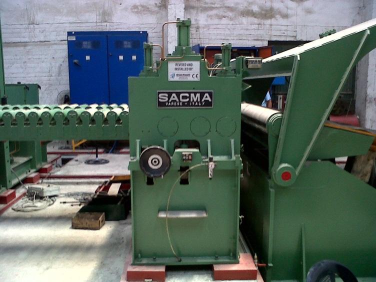
10 The PLC is a General Electric (GE) PLC. As seen in the figure above, in the left side of the cabinet, two colors of cables are connected to the PLC : -Blue cables are for input -Red cables are for output The inputs (24 Volts) come from sensors that are installed on the machine, from push buttons The outputs (110 Volts) are connected to electro valves, to contactors or to relays On the upper right side of the cabinet, the thermal circuit breaker are installed, this type of circuit breaker trips when excessive current passes through it and creates Joule heating of the bimetal and its deformation. This bimetal mechanically triggers a contact, which breaks the circuit protected. The electromechanical system is fairly simple and robust but not very precise and its reaction time is relatively slow. It is mostly used to avoid the direct trip of the circuit breaker when a motor is starting. 01

11 And below the thermal circuit breaker, we have 34 contactors, 26 of them control 13 synchronous motors (for forward and backward rotation) and the other are used to let the outputs of the PLC passes when the program requires it. So we started by pressing manually the contactors that control these motors to be sure that they are not defected. Now, and in the first machine of the line, we still have 5 DC motors that are controlled each one by a drive. One is for the first stage of the straightening, the second is for the leveler, the third for the cutting part, and the fourth and fifth for two conveyors after the cutting. Each drive has his own cabinet. We connected each cabinet to electricity, but some problems occurred. In the first one, the drive didn't work. After checking all the components (contactors, relays, filter, fuses) we found out that one fuse is defected, and when we changed it the motor worked as needed in the JOG mode. In the third cabinet, the motor turned in a unusual way, at a high speed but not in a regular way: it turn normally, for a certain time, and then suddenly the speed rises sharply. That's why the first thing we checked was the encoder since it is the device that is connected to the drive and according to it the speed change. So we disconnected it from the motor, and dismantled it. We discovered that the disk that is the main part of the encoder was scratched. So we took the necessary information from it (2500 pulses and dimensions) and we ordered a new one and installed it, in this way the problem was resolved and the motor turned normally. In the other drives we didn't face any problem. 00

12 2.2) PLC The heart of the line, and the main component, is the PLC. A programmable logic controller (PLC) is a digital computer used for automation of electromechanical processes. Since in this machine the PLC was already installed by the Italian company, we started by listing all the inputs and outputs and, tracking them. The sensors used in this line are: a) Inductive sensor, it is and electronic proximity sensor, which detects metallic objects without touching them. They are used in our line to take notice that the metal is present in the particular part where it is installed. It is used in the first straightening part, and before and after the cutting. If these sensors didn't return 24 volts it means the metal isn't present and the machine will no longer continue working waiting for the presence of the material, or it is used for the homing of the knife, (the zero position of the knife is detected when a metallic plate, welded to the axe of the motor, passes in the middle of the sensor as shown in the picture, in that moment the zero position is achieved). b) Limit switch, it is operated by the motion of a machine part or presence of an object. It marks the end of the movement of any object. It can cause the stop of the motor, or gives a signal (24 volts) to the PLC 02

13 to stop feeding the electro valves or the contactor to stop the movement. It ensure the safety of the people and the line itself. There two kinds of push buttons, normally open and normally close buttons. The normally close push buttons are used usually as emergency buttons. In case we push them they would be opened and it will stop feeding the input of the PLC, that's how the PLC will stop the line according to the program to ensure the safety and avoid any damage especially on humans. The normally open push buttons are connected to the PLC, only when they are pushed they will feed the PLC with 24 volts at the input, and according to the program an output will be on. 03

14 The listed above sensors and push buttons are connected to the inputs of the PLC. The output of the PLC could be either used to command a contactor which in its turn make a motor work, to command a relay, or to feed an electro valve with 110 volts to it could work. When we finished listing all the inputs and outputs, we connected the PLC to the electricity. A LED light turned on to indicate that the PLC is on. We thought that it was working, but after pushing the push buttons no input was on, so we considered that there was an initial condition that should be on so the PLC could work. We tried to cover the sensors hoping that this action will give the run order to the PLC, but it didn't, so after looking to the not connected inputs, we found that the input number 1 was one of several. So we gave it 24 volts from a transformer and the PLC worked. From that moment we started discovering the program by pushing the push buttons and noticing which output will go on. We tried all the possible combination of inputs to get a more specific view of the concept of the line. As it was predicted the motors worked perfectly but in the manual mode but this time through the PLC command. We still have to work on the hydraulic system. 04

15 2.3) Hydraulic system Since the heart of the line the PLC worked, the only remaining part of the line that was not working was the hydraulic system. The essential part of the hydraulic system is the hydraulic pumps that supply fluid to the components in the system. Pressure in the system develops in reaction to the load. Hence, a pump rated for 5,100 bar is capable of maintaining flow against a load of 5,100 bar. This pump was not connected to the electricity nor to the hydraulic system. So the first step was to connect it to the electricity to be sure that it works, but since it is a 15 KW pump it is preferable not to connect it directly, but pass it by a soft starter which is a device used with AC electric motors to temporarily reduce the load and torque in the powertrain of the motor during startup. So we installed a soft starter, a contactor and a thermal circuit breaker before the pump. The regulation of the soft starter was made in a way that the motor start with an initial low voltage and a delay time to avoid high current at the startup. 05

16 Once the pump was tested, the next step was to make a study of the hydraulic system because it was not complete: pipes and control valves were missing. Since the concept of the machine and the mechanical movements were known, we build our study basing on the pre-existing hydraulic system, to be able to accomplish it. So we followed each pipe to where it is connected, and listed the piston as shown in the catalogue. The missing pipes and electro valves are the ones that are related to the decoiler and the coil opening table. Our main sources of information regarding this subject, since 06

17 we are electrical engineers, were Dr. Eid, the internet and the shops where we visited to take quotations of the valves that we needed to purchase. It was very important to know the mechanical movement of the line so we could complete the missing part of the hydraulic system. Directional control valves or electro valves, route the fluid to the desired actuator. They usually consist of a spool inside a cast iron or steel housing. The spool slides to different positions in the housing, intersecting grooves and channels route the fluid based on the spool's position. The spool has a central (neutral) position maintained with springs; in this position the supply fluid is blocked, or returned to tank. Sliding the spool to one side routes the hydraulic fluid to an actuator and provides a return path from the actuator to tank. When the spool is moved to the opposite direction the supply and return paths are switched. When the spool is allowed to return to neutral (center) position the actuator fluid paths are blocked, locking it in position. To get a more controllable system we added to the electro valves, pressure regulators that reduce the supply pressure of hydraulic fluids as needed for various circuits. And to maintain a more neutral position and for the piston not to come back to the initial state, we installed check valves which are one-way valves, allowing an accumulator to charge and maintain its pressure after the machine is turned off. In total we bought and installed eight electro valves with its necessary piping. 07

18 After installing them, we needed to connect the coil of the electro valves to the PLC. There was push buttons and switches in the control panel that are connected to the PLC and when they were pushed, outputs were going on but these outputs weren't connected to any element of the line, and the number of these push buttons and switches were the same as the number of the electro valves, which made us more sure about the wiring that we were doing. After completing the hydraulic system, it was time to test it once we have filled up the reservoir of the pump with the desired fluid. We turned on the pump; the first thing we noticed was leakage in multiple places. A detailed inspection was made on every pipe to make sure that there is no leakage because in case it occurs, the pressure in the hydraulic system will drop enormously which will cause a loss of precision and functionality. The study and purchase of the valves was our responsibility, but their installation was made by the mechanical technicians in the plant. We refilled the reservoir with the fluid and started examining each movement to ensure they work as planned. In some cases were the movement was reversed, we had either to change the connection of the cables that are connected to the coils of the electro valves, or, if installed a one way valve, we replaced the return pipe by the main pipe and vice versa, which are both connected to the same plate, in this method 08

19 we reversed the movement. At that point, we have a fully tested and working electrical and hydraulic system, but in the manual mode, now we have to try to run the machine in the automatic mode. 09

20 2.4) Automatic mode + synchronization In the manual mode, we made sure that the PLC and the hydraulic system are working by feeding the inputs, through the sensors and the push buttons, to get the outputs and then a mechanical movement. But now, to run the machine in the automatic mode, surely in the PLC there are conditions that should be satisfied first. Since the program of the PLC was not available for us, we needed to use our logic as engineers, to predict the way that the program was written by using a trial and error strategy. This work demanded from us the full knowledge about the PLC input, and the concept of the machine. In the automatic mode, all drives should be ready to work in the same time and speed, so the enable signal must be received by the drives at the same time. After checking the connections between the electrical cabinets that contain the drives and the one that contains the main PLC, we found that there is a single cable from each cable that enters the cabinet of the PLC. These cables are connected to different relays, each one is controlled by a different output. Our first reaction was to push the button that is considered to make the machine run in the automatic mode since it is called "Marcia" by the company. So when we pushed it, since it is connected to the PLC, an input is turned on, and at the same time an output, but the machine didn't run. And above that, when the button isn't pushed, the output will turn off, so there is no maintain for the output. So we predicted that there is some conditions that should be fulfilled before it will work automatically. Putting steel in front of sensors, pushing limit switches, all of that didn't work. So we started thinking in a new vision, since we knew the relays that by it passes the enable cables of the drives, we took the output of the PLC that is turned on when "MARCIA" is pushed, and we made a circuit to maintain a relay on when the button is pushed, and off when stop is pushed. The push button stop is a red 21

21 button located under the "MARCIA" button. This relay controls all the relays responsible of the enable signals. Now we have a button that makes the enable signal pass from the output of the plc to the drives. As any other drives, the speed of the motor is determined by an analogue voltage that feeds an input in the drive, it is called speed reference. In our case, the speed reference of the drive that control the leveler is connected to a potentiometer on the control panel. That same potentiometer feeds the input of the first conveyor directly so it will have the same speed, and it feeds the input of the second conveyor through a resistance to decrease the voltage so the second conveyor will be slower. In the case of the drive that controls the first stage of straightening, it didn't work in the automatic mode, but in the jog mode it worked perfectly, so we started looking in his parameters, nothings was unfamiliar, we looked in its input, the speed reference was missing. In theory, the speed of this motor should be the same as the leveler since it is located just before it and from it the steel enters the leveler. To avoid any damage to the drive, we should know the maximum voltage that the input of the speed reference could tolerate, so we couldn't simply connect the same speed reference as the other drives. So by connecting to the input a variable DC 20
22 voltage and by observing the speed of the motor, we concluded that the maximum voltage that the speed reference could tolerate is 10 V. So we should take from the other drives a DC output that changes with the speed. We found one by simply changing the speed of the first motor and measuring each voltage of the output of the drive. But this output varies between 0 and 80 V. Connecting this output directly will cause a serious damage to the drive, we needed to decrease that voltage, so we passed the cable through a variable resistance. The main difficulty that confronted us was the synchronization between the motors of the first stage of straightening and the leveler because the steel is pulled by the leveler from the straightening part. This synchronization is determined by the resistance that we added between the two drives. To determine the value of the resistance, we didn't have any choice but to take measurement of the speeds of the two cylinders (since the motor isn't directly connected to the cylinder, but it is connected first to a gearbox than to rotating axes). Our goal was to make the leveler turn in the same speed as the first stage of 22
23 straightening. But originally the levelers' speed is shown from an analogue display that shows' the speed in meter per minute. And we have taken the speed of the other part in round per minute, by fixing on the cylinder a piece of metal and on the body of the line that is already fix a sensor. We made the motor turn with a specific value of voltage entering the speed reference, and we measured the speed of the cylinder in round per minute (by measuring the time in minute between two consecutive signals of the sensor) and having the radius of the cylinder we get the speed in meter per minute. So we compared the two values with each time changing the value of the resistance until we got the same speed. Then we fixed that value of resistance and started testing if we changed the speed of the leveler, we get the other speed the same. With this method we got the fully synchronization of these two motors. Now we still have the last part of the machine that didn't work in the automatic mode, the cutting part. This part of the machine has its own PLC, HMI and drive. The concept of this part is that the length of the steel needed to be cut is entered into the HMI which in its turn is connected to the PLC. In the PLC, this number compared to another number which is the signal that comes from the encoder. The encoder is also connected to the PLC. So the encoder return to the PLC the length that is entering in that particular moment, when that number is equal to the one entered by the operator, the drive get an enable signal and turn knife so it could cut the steel. The initial condition for that concept to work is that the PLC receives a signal from a sensor installed before the cutting part which indicate the presence of steel. 23
24 After cutting the steel, the knife should go to the zero position in his trajectory to avoid any collision when the machine is running in the automatic mode. This phenomenon is called homing. The homing sensor used is described in the first part of the report. And finally, the safety of the people and the line is very essential, so making sure that all the emergency push buttons works is very important, even the operator demanded us to put more emergency push buttons on the machine, so we did by putting them in series with the other buttons that are connected to an input of the PLC. Now we have a system that works automatically by a simple button if all the initial conditions are satisfied. In conclusion, the initial conditions are, we put the length of the metal sheets that we want, no emergency push button are pushed, there are no faults in the drives, the sensor at the beginning of the line should be on for the PLC to acknowledge the presence of metal, and finally the hydraulic and electrical system are in a good condition. 24
25 Chap 3: Second machine in the line 3.1) Electrical and pneumatic system 3.2) Programming a new PLC 3.3) Wiring 3.4) Load cell 25
26 3.1) Electrical and pneumatic system The second machine in the line is the one that is responsible of the accumulation of the metal plates after being cut. It is divided into two parts according to the length of the metal plate. If the plate has a length less than 5 meters, only the first part will work, and if the plate is longer, the two parts will work simultaneously. The electrical system of this machine is constituted of one PLC (OMRON), two drives that controls two AC motors for two different conveyors, seven counters located in the control panel and a number of relays and contactors. As the previous part of the line, we don't have the program of the PLC nor the electrical drawings. Since the strategy practiced in the previous part of the line has been successful, we started by identifying all the electrical part in this machine and trying to understand the concept upon which this machine run. Only by the observation of the elements of the machine, we could understand that it works basing on the sensors. What helped us in this case was that on the cable tray, below the contactors, a name that indicate the motor that the contactor control was written by the Italian company, 26
27 and that let us concentrate more on the sensors and the encoders. By following the cables of each sensor, we indicated the inputs to which they are connected and predicted the role of each one basing on its position in the machine. We made sure that those cables were in good condition. Once the sensors were listed, we started by exploring the electrical cabinet and the control panel. On the control panel seven counters are installed, each one is connected to an encoder that determines the linear displacement of the mechanical part that the motor moves. Now it was the time for checking if anything is missing in the machine. The first thing we noticed is that an encoder was missing, its' cable was connected to the counter and in the other side was hanging in the air. This encoder is located at the end of the machine and to be sure what kind of encoder it was, we dismantled an existing one that is in front of the machine and that in theory should be the same. So we looked in its' characteristics (500 pulses), and we bought a similar one and connected it. When we opened the cabinet, we noticed a capacitor that was connected in parallel with a bridge that gives 24 volts, it was obviously damaged so we changed it. Its' role was to avoid any drop-voltages and maintain a stable voltage. Since the PLC is the heart and mind of the machine, we started by checking all the inputs and outputs. The inputs are connected either to push buttons, or to sensors or to the counters indirectly since the cables are passing by series of relays that are especially related to the counter. Plus, we have a control panel, other than the main one, which is placed on the body of the machine. From this control panel, and since below the buttons are written their names, we traced the cables of each push button and we concluded that they were connected in parallel to other push buttons in the main control panel, and to the PLC. Some of these push buttons were the run button, 27
28 automatic and manual button The outputs controls the contactors, relays, and pneumatic electro valves. It was time to connect the cabinet to the electricity and see if we could run it without changing the PLC. The next picture shows the state of cabinet when we just opened it. We could see the bad condition and the huge number of cables which made it harder to us to work and to completely explore the wiring. After connecting the panel to the electricity, the PLC and the counters were working in a normal way. So we started testing all the push buttons and taking knowledge of which output will be turned on and which mechanical movement will occur in the machine since the program of the PLC is unknown. In the pneumatic system, many leakages were noticed. This system is installed by the Italian company itself. The reasons of the leakages were mostly of damaged tubes. They were repaired by the technicians of the factory. Once the pneumatic system was complete and running in a normal way, we continued 28
29 our work on the electrical system. So we continued what we were already doing, every push button was tested and taking knowledge of the mechanical movement that it produces. As mentioned above, there were 7 counters; each one is connected to a different encoder related to a motor. The principle of the counter is that we enter a number to the HMI, that number represents the distance that we need it for the motor to move the part that he is related to corresponding to the zero position. When the movable part attend the limit switch, we should make the counter reads zero. So we looked on the internet for the catalogue of the counter named QEM. We looked for the procedure to make a counter reset to zero. We finally discovered it, and made all the necessary calibrations of the machine, and returned all the parts that are moved by the counters to their initial place and zeroed all the counters. The counters controls the motor that moves the parts listed below: 1. Conveyor which receives the plates after being cut. It is moved according to the width of the plates. 2. Straightener in the first part of the machine, left side. It presses the accumulated plates after being dropped from the first conveyor between the two straightening parts from the right and left. It is also moved according to the width of the plates. 3. Straightener in the first part of the machine, right side. 4. Straightener in the second part of the machine, left side. 5. Straightener in the second part of the machine, right side. 6. The part that blocks the way of the metal so they would fall 29
30 approximately at the same place. One is located in the first part of the machine, and it is moved according to the length of the plates. 7. Blocking part in the second part of the machine. After trying the counters, we checked that all the motors are turning in the right direction, and that all the sensors are returning 24 volts to the input of the PLC. At that moment we were sure that no problems exists in the electrical system, and we should try to run the machine in the automatic mode. The first normal reaction was to push the button that is named automatic, but nothing happened. We predicted that there should be initial condition like any program to run the machine automatically. We tried every scenario, by letting the sensors return 24 volts, even by trying every contactor or relay since in the first machine the automatic mode was discovered through a relay, but still no results. We looked for cables between the two machines, we found one, but it is coming from the drive of the conveyor of the first machine, to the drives of the second machine. It is used as a speed reference so the whole line will work at the same speed. We didn't have anymore hope since we tried everything. So after consulting Dr. Eid, we decided to take a new approach for the project. 31
31 3.2) Programming of a new PLC Since our goal was to make the machine run automatically, and itwas impossible with the PLC programmed by the Italian company, we decided to make by ourselves a new program for this part of the line since we are familiar to the concept of the machine, and we knew each mechanical movement that the motors and the electro valves do. First we needed to choose which PLC we would work on. And that choice is mostly affected by the price of the PLC, its availability and the decision of the owner. Before determining the mark of the PLC, we needed to determine the number of inputs and outputs that we need. We draw the concept of the machine in the Grafcet mode so we could have a more realistic number of inputs and outputs, and to make the concept of the machine more clear. We didn't take the same number of inputs as the already programmed PLC since each person has a way of thinking even if we have the same machine. So after drawing the Grafcet program, we knew that we want to choose a PLC that could tolerate: inputs distributed between limit switches, sensors and push buttons, outputs, used to control relays, We started looking for a PLC that is not very expensive, heavy duty, and has that much of inputs and outputs. Our first choice was to use an already existing PLC in Dr. Eid company, its mark was LG. But we needed to make sure that it could be extended to support the big number of input and outputs. After a long research in the internet we found out that the PLC available was not extendable. 30
32 So we purchased a Delta PLC, his type is DVP-EX2, and a human machine interface, DOP-B. The HMI is purchased under the demand of the owner of the factory, he wants to see how much plates are being cut, enter the number of plates to be accumulated, and the number of stacks. First of all, we downloaded the operational manual of the PLC to know all the Ladder logic symbols and the memory map. X represents the external inputs, Y external outputs, M auxiliary relay, T timer, C counter, D data register and K a constant. We started by programming the HMI. Three numerical entries were put in the first page of the HMI, one for the number of plates in one stack, the second for the number of stacks and the third for the length of the plates. When we touch the HMI at the numerical entry, a numerical keypad will appear where a number is entered and saved in a data register in the PLC. In the second page of the HMI, we placed an indicator that shows to the operator the number of plates that entered the machine, and the number of stacks that leaved the machine. Under the indicator, a start and stop push buttons are placed for the operator so he could manage the automatic run of the machine. The start and stop push buttons are considered as inputs in the PLC. Once the HMI is programmed, we started by writing the program. We tried to use all the resources in the machine, which means that we based our program on the push buttons and sensors that are already installed, even some of them we didn't use it at all. At the beginning of the machine, three sensors are already installed in the front, we used two of them to detect the metal, but each one has his own role. The first one (capacitive sensor) is connected to the input of the PLC, and in the program it counts the number of plates that enters the machine. The second one (photoelectric sensor) is 32
33 used to slow the speed of the conveyor when a plate enters the machine by controlling a relay, in the normally close position, 24 Volts is connected to the speed reference of the drives of the conveyors, and when the relay is on, 24 volts passes through a potentiometer to decrease the voltage and then enters the speed reference of the drive.once the plate enters into the machine, the counter in the PLC increases by one. When the whole plate enters the machine, and at the edge down of the sensor, the PLC, through the outputs, gives order to two electro valves, right and left side of the machine, to open the conveyor that holds the plate. On the piston that moves the conveyor, two sensors are installed, one at the beginning and the second at the end. So once the conveyor opens, the sensor at the end of the piston will be on, and return to the PLC 24 volts, at that moment, the PLC orders the electro valves to close until the sensor at the beginning of the piston is on. Meanwhile, the plate will fall into another conveyor. And to ensure the safety of the machine, we installed a sensor that if the height of the accumulated plates attend this sensor, the conveyor will descend for a second. Since the machine is composed of two parts, and if the plates are more than 5 meters, the conveyor of the second part will follow the first one since between the 33
34 two conveyors there are 3 sensors aligned to determine which way the first conveyor went so the second can follow, and the sensor in the center determine the alignment of the two conveyors. But if the plate is less than 5 meters, the conveyor of the second part will be separated from the system and won't move because the clutch that connects him to the motor will be off. All these options are ordered by the PLC according to the number entered by the operator. With every plate falling from the conveyor, two metal plates along the second conveyor will press the accumulated plates so they would be aligned. This movement is controlled by the PLC outputs that are connected to electro valves on both sides, also according to the length of the plates. This operation will continue until the number of plates that entered into the machine and present on the second conveyor are equal to the number entered by the operator. As an initial condition, the conveyor on which the plates are dropped, if empty, should be at the highest position that is determined by a limit switch since it moves on four vertical axes at the four edges, or if already holding a certain number of plates, it rises until a capacitive sensor turns on which indicate that the plates are present on the conveyor and it could not reach the limit switch. 34
35 From the moment that all the wanted plates are on the second conveyor, the conveyor start to descend and stops at the limit switch that we determined its position. Than it turns forward so the plates would come out of the machine on the way to the load cell. If the plates are longer than 5 meters, we will have the same scenario as discussed above, but if the plates are less than 5 meters only the first part of the machine will work, which means that the conveyor of the second part will stay at the lowest position, all the time, just it will turn forward when the stack of plates will go out of the machine. To notice that once the number of plates is achieved, and just before the conveyor descend, the first machine in the line will stop to avoid any plate entering the second machine, and it will run again when the stack gets out of the second machine. For the automatic mode, we programmed our PLC according to the concept described above. And in the manual mode, each mechanical movement has its own push button that enters the PLC and an output that controls it. The only things that could limit these movements are the limit switches that are installed to prevent the machine from any damage. A switch connected to the input determines in which mode the machine will run, manual or automatic mode. And to ensure that the whole line will work as a single unit, we made by a simple wiring by connecting the run machine output in parallel with the "Marcia" button, so we could, by the start button in the automatic mode of the second machine, make the whole line work automatically. And the same thing with the stop button. 35
36 3.3) Wiring Once the program was written, we went to the factory and started dismantling the electrical cabinet. As seen above in the picture of the electrical cabinet, it was in a mess in a way it was difficult to locate a cable. So we started by dismantling the PLC, and before taking of the cables from it, and from the tags on them, we knew if we need this wire or no. If we needed it we will keep it in place, if no we would cut it from the entry of the cabinet and pull it. In this way we clean and rearrange the cabinet so it would be more organized and clean. After finishing this process, we removed the old PLC and installed the new one. To prevent any future problems in the PLC, and to protect the outputs from over current, we installed after each output a relay. This relay is controlled by the PLC and when it is on, it connect 220 volts or 110 volts, to the part that we want to control. Each relay we installed was labeled according to its functionality. So after installing the relays, we started connecting the inputs and outputs that we have in the new program according to a list made by us, and that would help us win some time and be more organized. The next picture shows the big difference between the old and the reorganized cabinet. 36
37 After finishing the wiring, we connected the cabinet to the electricity and started at first the manual mode. All what we planned for worked properly. Now it was the time for the automatic mode which for us was the biggest challenge. We put the switch into the automatic mode, and we started testing the program. Since we knew the initial conditions, it was easy for us to launch this program. Some modifications were made upon the demand of the operators, even some changes in the positions of sensors were made to ensure the perfect work of the machine. But in total no big changes were done. The result of our program is shown in the picture below. 37
38 3.4) Load cell Once a stack gets out of the second part of the machine, it should pass over a load cell for measuring the weight. A load cell is a transducer that is used to convert a force into electrical signal. The cables of the load cells were not connected, as seen in the picture above. so we connected them to the counter that is specific for this load cell. After looking into the electrical cabinet and taking a good look into the wiring, and since there is no connection between this system and the other machine, we concluded that it is a standalone system. The first step was to connect the cables coming from the machine, sensors and the motors. After connecting the cabinet to the electricity, nothing have worked, even when forced the sensors to be on. We consulted the operators and they decided that they want the system to work only manually. Once the plates get out from the second machine, a switch installed in the control panel makes a conveyor move the stack to another one that is placed above a load 38
39 cell. This load cell measures the weight which appears on a counter. Than manually and by a switch, the conveyor transport the plates to another conveyor and stay there until the operator takes them away. So the control of the conveyors is manual by switches. And to ensure more safety for the line, we installed an inductive sensor under the first conveyor and connected it to the newly installed PLC. This sensor is used to make sure that when the line is running, there is no stacks waiting at the exit of the line. So when the sensor returns 24 volts, the line should stop waiting for the operator to transport it. The previous picture shows the cabinet before we disconnected all the wiring, and remade it according to the new concept using only contactors, switches and relays. 39
40 Conclusion This project demanded from us our total concentration and time, our way of thinking as engineers helped to resolve all the problems that came into our way, and to invent and fill the gaps. Not only we made the machine run as we hoped, but we learned so much things from this project with the help of Dr. Georges Eid and the technicians that we worked with in the factory. The trial and error strategy was our strategy in the first machine since we didn't have any electrical drawings and we didn't knew the program of the PLC, but in the second we invented our own concept of the machine and programmed a PLC. Our goal was achieved when we saw the line working and metal plates were cut and accumulated as it should be, and we transformed a metal coil into metallic plates cut according to any length and packed in any number that we want. Before: After: 41
41 Appendix A A.1) Electrical catalogue Trolley The coil is placed over this trolley and used to transport the coil over a vertical piston. Decoiler(right part) This decoiler is used to unroll the coil.( RIGHT PART). We have in this part 2 electro valves that move the decoiler right or left. 40
42 Brake for the turning clams part in the decoiler These electro valves installed by us are for these movements: for the up and down of the vertical piston, open and close of the clutch in the decoiler (one for the right decoiler, and another for the right one), turn forward and backward of the decoiler (one for the right decoiler, and another for the right one) 42
43 Coil opening table This picture shows that when we started our project, these electro valves where not installed, but according to our studies they were purchased and added to the system. Their role is to control the up and down of the table and the two vertical piston. Limit switch: To limit the move of the table to ensure its safety. 43
44 First stage of straightening These valves are used to move down and up the cylinders to change the pressure on the plate. This sensor is used to detect the metal before getting into the leveler. This motor rotates the cylinder to help the decoiler pull the metal. 44
45 Leveler The leveler is the part that is mainly responsible of the straightening of the metal. This motor is used for adjusting the pressure of the cylinders on the metal on the right side by changing the slope of the movable part of the leveler. This motor is used for adjusting the pressure of the cylinders on the metal on the left side by changing the slope of the movable part of the leveler. 45
46 This motor adjusts the pressure of the cylinders on the metal in front and back of the leveler in the right side. This motor adjusts the pressure of the cylinders on the metal in front and back of the leveler in the right side. These valves are used to move down or up each line of cylinders to get more efficiency in the leveling. 46
47 ` These limit switches are used to define the maximum slop that the leveler could achieve. Pinch Roll In this part of the machine is placed the encoder that according to it the PLC knows the length of the metal that entered under the knife. These electro valves controls the pistons in this part that moves up and down the cylinders. 47
48 This sensors indicate the presence of the metal before it enters the cutting part. Rotary Shear This part of the machine is the cutting part. This sensor is used for the homing of the knife 48
.")

49 A.2) Hydraulic catalogue Part 1: Decoiler P1: piston 1 ( to move left the coil ). P2:piston 2 ( to move right the coil ). J1: junction 1 L: lift ( to pull up and pull down the coil ). 49


50 C: clamps (to clamp the coil ). P.C: pressure control H1: hydraulic system 1 E.V: electro valve M: motor T: tank J2 : junction 2 51


51 1 to 11 : number for each pipe Part2 : Coil opening table ` 50

52 P1: piston 1 P2:piston 2 J1: junction 1 L: lift J2: junction2 52

53 Part 3 : straightening 53

54 P1:piston 1 P2: piston2 P3:piston 3 M: motor E.V: electro valve 54

55 Part 4 : Leveler 55
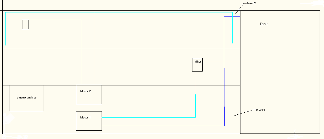
56 Level 1 Level 2 56


57 Part 5 : Pinch Roll 57

58 Close view to the junction Piston 1 Piston 2 Motor 58

59 Part 6 : Rotary Shear 59

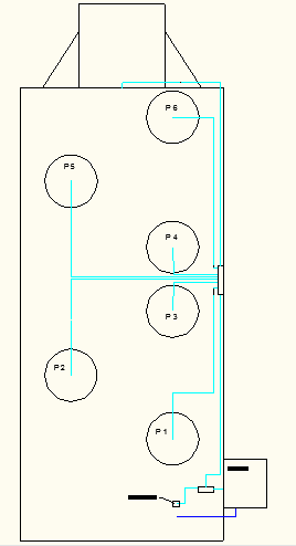
60 P1: piston 1 P2:piston 2 P3: piston 3 P4: piston 4 P5: piston 5 P6:piston 6 Motor Junction going to opposite motor on the other side 61
61 Appendix B. B.1) The program of the PLC Kindly find the PLC program in the XPS File. 60

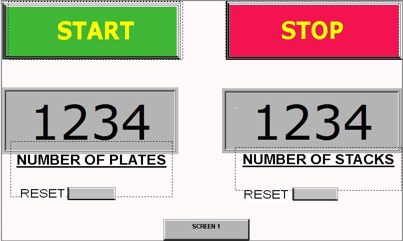
62 B.2) HMI Counters Indicators 62
Sensors Collecting Manufacturing Process Data
 Sensors & Actuators Sensors Collecting Manufacturing Process Data Data must be collected from the manufacturing process Data (commands and instructions) must be communicated to the process Data are of
Michelin North America
 www.centecinc.com SC Telephone: 864.527.7750 Outside SC: 800.227.0855 Michelin North America Industrial Maintenance Technical Interview Outline Industrial Maintenance Technical Interview Outline The Technical
Fig 3. PLC Relay Output
 1. Function of a PLC PLC Basics A PLC is a microprocessor-based controller with multiple inputs and outputs. It uses a programmable memory to store instructions and carry out functions to control machines
Unit 24: Applications of Pneumatics and Hydraulics
 Unit 24: Applications of Pneumatics and Hydraulics Unit code: J/601/1496 QCF level: 4 Credit value: 15 OUTCOME 2 TUTORIAL 4 DIRECTIONAL CONTROL VALVES The material needed for outcome 2 is very extensive
How to read this guide
 How to read this guide The following shows the symbols used in this Quick start guide with descriptions and examples. Symbol Description Example P oint Reference Caution [ ] This symbol explains information
TOYOTA ELECTRONIC CONTROL TRANSMISSION
 Electronic Control Transmission (ECT) The Electronic Control Transmission is an automatic transmission which uses modern electronic control technologies to control the transmission. The transmission itself,
CIM Computer Integrated Manufacturing
 INDEX CIM IN BASIC CONFIGURATION CIM IN ADVANCED CONFIGURATION CIM IN COMPLETE CONFIGURATION DL CIM A DL CIM B DL CIM C DL CIM C DL CIM B DL CIM A Computer Integrated Manufacturing (CIM) is a method of
..OR How To Protect your 3-Phase Equipment Investment with 3-Phase Monitors from Time Mark...
 ..OR How To Protect your 3-Phase Equipment Investment with 3-Phase Monitors from Time Mark... TIME MARK CORPORATION 11440 EAST PINE STREET TULSA, OK 74116 USA tel 918 438-1220 fax 918 437-7584 www.time-mark.com
CNC HARDWARE & TOOLING BASICS
 Computer Aided Manufacturing (CAM) CNC HARDWARE & TOOLING BASICS Assoc. Prof. Dr. Tamer S. Mahmoud 1. Parts of CNC Machine Tools Any CNC machine tool essentially consists of the following parts: Part Program,
Electronic Power Control
 Service. Self-Study Programme 210 Electronic Power Control Design and Function With the Electronic Power Control system, the throttle valve is actuated only by an electric motor. This eliminates the need
Test Code: 8094 / Version 1
 Blueprint Electromechanical Engineering Technology PA Test Code: 8094 / Version 1 Copyright 2014. All Rights Reserved. General Assessment Information Electromechanical Engineering Technology PA Blueprint
PALLETS ROLLER CONVEYOR LOADING CONVEYOR CHAIN TRANSFER TURNTABLE ROLLER STOP
 AUGUST 12, 2014 INDEX 04 07 04 06 EMITTER REMOVER 07 08 10 12 14 BOXES BELT CONVEYOR BELT CONVEYOR GATE STRAIGHT SPUR CONVEYOR CONVEYOR SCALE 16 17 18 19 20 22 24 26 ALIGNERS WHEEL ALIGNER BRACKET CHUTE
Electrical Systems - IQAN Digital Control System. IQAN Control System Components... 5.1.3
 Section 5.1 Electrical Systems - IQAN Digital Control System IQAN Control System Components........................... 5.1.3 IQAN Operational Description: At Machine Startup.....................................
Electrical Symbols and Line Diagrams
 Electrical Symbols and Line Diagrams Chapter 3 Material taken from Chapter 3 of One-Line Diagrams One-line diagram a diagram that uses single lines and graphic symbols to indicate the path and components
understanding medium frequency induction melting furnace and its components
 understanding medium frequency induction melting furnace and its components 9 Spruce Street, Jersey City, NJ 07306 USA sales@electroheatinduction.com INDUCTION MELTING FURNACE AND ITS COMPONENTS The purpose
PLC Based Liquid Filling and Mixing
 PLC Based Liquid Filling and Mixing 1 Mihir Panchal, 2 Aashish Panaskar. 3 Prof. Lalit Kumar KJ College of Engineering and Management Research, Pune, India Abstract: The objective of this paper is to design,
PROGRAMMABLE LOGIC CONTROLLERS Unit code: A/601/1625 QCF level: 4 Credit value: 15
 UNIT 22: PROGRAMMABLE LOGIC CONTROLLERS Unit code: A/601/1625 QCF level: 4 Credit value: 15 ASSIGNMENT 3 DESIGN AND OPERATIONAL CHARACTERISTICS NAME: I agree to the assessment as contained in this assignment.
Electronic Manual Gearbox
 Service. Self-Study Programme 221 Electronic Manual Gearbox Design and Function Taking the Lupo as the basis, Volkswagen has developed the world's first 3 L car that will also go into volume production.
i ChatterBox! Motorcycle Security
 i Before you Start the Installation * Please read this manual to become familiar with the requirements necessary to complete the installation. * Use a high quality multi-meter to test all wires before
HERZ-Thermal Actuators
 HERZ-Thermal Actuators Data Sheet 7708-7990, Issue 1011 Dimensions in mm 1 7710 00 1 7710 01 1 7711 18 1 7710 80 1 7710 81 1 7711 80 1 7711 81 1 7990 00 1 7980 00 1 7708 11 1 7708 10 1 7708 23 1 7709 01
SECTION G2: CABLE PROCESSOR MODULE MAINTENANCE
 SECTION G2: CABLE PROCESSOR MODULE MAINTENANCE Cable Processor Module overview WARNING! When tipping the Cable Processor Module back, (after removing the toggle arm pin), use extreme caution not to drop
1115 4G SERIES GOVERNOR. 4-20 ma ANALOGUE DIGITAL SPEED SETTING
 1115 4G SERIES GOVERNOR with 4-20 ma ANALOGUE & DIGITAL SPEED SETTING PO Box 28, 9300AA Roden, The Netherlands Tel: +31 505019888 Fax: +31 505013618 E-mail: regulateurs@regulateurs-europa.com 1115 4G
Subminiature Load Cell Model 8417
 w Technical Product Information Subminiature Load Cell 1. Introduction... 2 2. Preparing for use... 2 2.1 Unpacking... 2 2.2 Using the instrument for the first time... 2 2.3 Grounding and potential connection...
Trouble shooting for die cast machine. customer service department of L.K Group
 Trouble shooting for die cast machine customer service department of L.K Group A. Faults Detect and the Steps for Repair Important When faults occurred on die casting machine operation. Operators should
TMS TANK MANAGEMENT SYSTEM
 TMS TANK MANAGEMENT SYSTEM Page 1 of 9 Operating Instructions GENERAL The Tank Management System is a bespoke design to control, monitor and accommodate efficient storage and dispensing of TMS. FUNCTIONS
Designed for multi-injector endurance testing, the
 Designed for multi-injector endurance testing, the ETB Test Bench can optionally provide shot-to-shot mass measurement. The injectors are precisely subject to variable controls and hydraulic pressures
Brake module AX5021. Documentation. Please read this document carefully before installing and commissioning the brake module!
 Documentation Brake module AX5021 Please read this document carefully before installing and commissioning the brake module! Version : 1.2 : 2012.03.05 Date Article-no. : TDmlAX-5021-0000-0200 Page 2/8
High Security Heavy Duty Shredders VZ 14.00. Perfect shredding and high performance in DIN security levels 4 and 5
 High Security Heavy Duty Shredders Perfect shredding and high performance in DIN security levels 4 and 5 Documentation High Security Heavy Duty Shredders / Page 1of 5 Perfect shredding and high performance.
ABB ! CAUTION. Type COQ Negative Sequence Generator Relay. (50/60 Hertz) 41-161J. Instruction Leaflet
 41-161J. Instruction Leaflet") ABB Instruction Leaflet 41-161J Effective: May 1997 Supersedes I.L. 41-161H Dated July 1984 ( ) Denotes Change Since Previous Issue Type COQ Negative Sequence Generator Relay (50/60 Hertz)! CAUTION Before
ABB Instruction Leaflet 41-161J Effective: May 1997 Supersedes I.L. 41-161H Dated July 1984 ( ) Denotes Change Since Previous Issue Type COQ Negative Sequence Generator Relay (50/60 Hertz)! CAUTION Before
Industrial Automation Training Academy. PLC, HMI & Drives Training Programs Duration: 6 Months (180 ~ 240 Hours)
") nfi Industrial Automation Training Academy Presents PLC, HMI & Drives Training Programs Duration: 6 Months (180 ~ 240 Hours) For: Electronics & Communication Engineering Electrical Engineering Instrumentation
nfi Industrial Automation Training Academy Presents PLC, HMI & Drives Training Programs Duration: 6 Months (180 ~ 240 Hours) For: Electronics & Communication Engineering Electrical Engineering Instrumentation
Blender Notes. Introduction to Digital Modelling and Animation in Design Blender Tutorial - week 9 The Game Engine
 Blender Notes Introduction to Digital Modelling and Animation in Design Blender Tutorial - week 9 The Game Engine The Blender Game Engine This week we will have an introduction to the Game Engine build
CNC MILLING MACHINE TROUBLE SHOOTING. 1. Trouble Shooting. No Trouble Solution. 1.Check the air pressure
 CNC MILLING MACHINE TROUBLE SHOOTING 1. Trouble Shooting No Trouble Solution 1 Tool magazine( (Umbrella type) Noise for tool changing Can t change the tool Tool number in chaos Tool magazine keep rotation
Product Description Full Voltage Starting Electric Fire Pump Controllers FTA1000
 Product Description Full Voltage Starting Electric Fire Pump Controllers FTA1000 Description Firetrol FTA1000 Full Voltage Fire Pump Controllers are intended for use with electric motor driven fi re pumps
Unit 24: Applications of Pneumatics and Hydraulics
 Unit 24: Applications of Pneumatics and Hydraulics Unit code: J/601/1496 QCF level: 4 Credit value: 15 OUTCOME 2 TUTORIAL 3 HYDRAULIC AND PNEUMATIC MOTORS The material needed for outcome 2 is very extensive
543-0032-00, 943-0032-00. User s Manual
 543-0032-00, 943-0032-00 User s Manual 1 Comfort Alert Diagnostics Faster Service And Improved Accuracy The Comfort Alert diagnostics module is a breakthrough innovation for troubleshooting heat pump and
Schematic Symbols Chart (Design Hydraulic and Pneumatic circits)
") Page 1 of 6 (Home) Symbols / Visit us on: Fluid Power, Automation and Motion Control for all Industries About Us Products Services Catalogs Place an Order Training & Information Contact Us Employee Access
Page 1 of 6 (Home) Symbols / Visit us on: Fluid Power, Automation and Motion Control for all Industries About Us Products Services Catalogs Place an Order Training & Information Contact Us Employee Access
The Secret of Hydraulic Schematics. BTPHydraulics www.iranfluidpower.com
 The Secret of Hydraulic Schematics BTPHydraulics www.iranfluidpower.com www.iranfluidpower.com Table of Contents The Secret to Reading and Interpreting Hydraulic Schematics... 1 Hydraulic System Schematics...
Precision Miniature Load Cell. Models 8431, 8432 with Overload Protection
 w Technical Product Information Precision Miniature Load Cell with Overload Protection 1. Introduction The load cells in the model 8431 and 8432 series are primarily designed for the measurement of force
EXPERIMENT 2 TRAFFIC LIGHT CONTROL SYSTEM FOR AN INTERSECTION USING S7-300 PLC
 YEDITEPE UNIVERSITY ENGINEERING & ARCHITECTURE FACULTY INDUSTRIAL ELECTRONICS LABORATORY EE 432 INDUSTRIAL ELECTRONICS EXPERIMENT 2 TRAFFIC LIGHT CONTROL SYSTEM FOR AN INTERSECTION USING S7-300 PLC Introduction:
Model SETR-50 and SETR-51 Trim Tab Control
 Model SETR-50 and SETR-51 Trim Tab Control Pictured above is the SETR-50 with black switches on a gray background. The SETR-51 is identical except for the color, wherein it has black switches on a black
Email: 1 nrsapre@gmail.com, 2 dr.s.m.kumar@gmail.com
 INDUSTRIAL AUTOMATION WITH ELECTRO PNEUMATIC SYSTEM USING PLC & WIRELESS/LAN ENVIRONMENT - A REMOTE EXPERIMENT 1 Nitin Sapre, 2 Dr. S Mohan Kumar 1 Drives & Control Academy, Bosch Rexroth India Limited,
Oil and Coolant Circulating Heating System. Model - OCSM
 Oil and Coolant Circulating Heating System Model - OCSM Installation & Operation Manual 216280-000 REV 2 Identifying Your System The HOTSTART heating system is designed to heat fluids for use in marine
What Is Regeneration?
 What Is Regeneration? Braking / Regeneration Manual Regeneration Overview Revision 1.0 When the rotor of an induction motor turns slower than the speed set by the applied frequency, the motor is transforming
Section 5: Machine Overview
 Section 5: Machine Overview Machine Floor Plan Machine Specifications Sequence of Operation Theory of Operation Sensor Location Floor Plan 2007 Douglas Machine Inc. 5.1 Machine Floor Plan Figure 5.1: Machine
T146 Electro Mechanical Engineering Technician MTCU Code 51021 Program Learning Outcomes
 T146 Electro Mechanical Engineering Technician MTCU Code 51021 Program Learning Outcomes Synopsis of the Vocational Learning Outcomes* The graduate has reliably demonstrated the ability to: 1. fabricate
! WARNING. McDonnell & Miller Installation & Maintenance Instructions MM-217(I) Series 150S and 157S (Snap Switch, All Models except 157S-RB-P)
 Series 150S and 157S (Snap Switch, All Models except 157S-RB-P)") Series 150S and 157S (Snap Switch, All Models except 157S-RB-P) Low Water Cut-Off/Pump Controllers For Steam Boilers and Other Level Control Applications McDonnell & Miller Installation & Maintenance Instructions
Series 150S and 157S (Snap Switch, All Models except 157S-RB-P) Low Water Cut-Off/Pump Controllers For Steam Boilers and Other Level Control Applications McDonnell & Miller Installation & Maintenance Instructions
DC Motor control Reversing
 January 2013 DC Motor control Reversing and a "Rotor" which is the rotating part. Basically there are three types of DC Motor available: - Brushed Motor - Brushless Motor - Stepper Motor DC motors Electrical
PROGRAMMABLE LOGIC CONTROL
 PROGRAMMABLE LOGIC CONTROL James Vernon: control systems principles.co.uk ABSTRACT: This is one of a series of white papers on systems modelling, analysis and control, prepared by Control Systems Principles.co.uk
GUTTER MACHINE CONTROLS STANDARD
 GUTTER MACHINE CONTROLS STANDARD Note: determine what type of control package is installed on the machine. --more-- All operators should familiarize themselves with the appropriate controls prior to any
Comprehensive Range of Industrial Products and Solutions
 Comprehensive Range of Industrial Products and Solutions SAFETY AUTOMATION Micro Controllers Small Controllers Mid Range Controllers Large Automation Controllers Safety Programmable Controller Motion Controller
Unit 24: Applications of Pneumatics and Hydraulics
 Unit 24: Applications of Pneumatics and Hydraulics Unit code: J/601/1496 QCF level: 4 Credit value: 15 OUTCOME 2 TUTORIAL 2 HYDRAULIC AND PNEUMATIC CYLINDERS The material needed for outcome 2 is very extensive
DeviceNet Bus Software Help for Programming an Allen Bradley Control System
 FBP FieldBusPlug V7 DeviceNet Bus Software Help for Programming an Allen Bradley Control System DeviceNet Software Help for Programming an Allen Bradley Control System Contents Page General Purpose...
INSTALLATION MANUAL 3RP / 5RP 4-BUTTON SERIES VEHICLE SECURITY SYSTEMS
 3RP / 5RP 4-BUTTON SERIES VEHICLE SECURITY SYSTEMS INSTALLATION MANUAL Before you begin the installation Read the INSTRUCTIONS! Always use a multi-meter when verifying vehicle wiring. Before mounting the
UNIT II Robots Drive Systems and End Effectors Part-A Questions
 UNIT II Robots Drive Systems and End Effectors Part-A Questions 1. Define End effector. End effector is a device that is attached to the end of the wrist arm to perform specific task. 2. Give some examples
Fault codes DM1. Industrial engines DC09, DC13, DC16. Marine engines DI09, DI13, DI16 INSTALLATION MANUAL. 03:10 Issue 5.0 en-gb 1
 Fault codes DM1 Industrial engines DC09, DC13, DC16 Marine engines DI09, DI13, DI16 03:10 Issue 5.0 en-gb 1 DM1...3 Abbreviations...3 Fault type identifier...3...4 03:10 Issue 5.0 en-gb 2 DM1 DM1 Fault
Introduction to Process Control Actuators
 1 Introduction to Process Control Actuators Actuators are the final elements in a control system. They receive a low power command signal and energy input to amplify the command signal as appropriate to
ETZGAR CONVEYOR COMPANY Controls Section v12.05
 Section 7 Controls Page Description 7-1 Controls Index 7-2 Motor Data, Enclosure Rating and Abbreviations 7-3 Controls Safety Guidelines 7-4 Fixed Speed Controls Packages 7-5 Three Phase AC Variable Speed
Development of Combined Automatic Blade Control for Snow-Removing Grader
 Technical Papers Yukihisa Sakai In snowy regions, improving the efficiency of snow-removing machines has been called for so as to reduce the time and cost involved in clearing the roads of snow. As a means
Example. Fluid Power. Circuits
 Example Fluid Power Circuits To Enhance Symbol Reading Skills To Work On Circuit Reading Skills With Answers HI LO Pump Circuit 18 A1 B1 17 16 15 13 Set 14 2,000 PSI PG2 Set 500 PSI 12 11 7 8 10 PG1 9
Procurement Specification for a High Security Lift Arm Barrier (HSLAB) EB950 CR Armstrong High Security Lift Arm Barrier
 EB950 CR Armstrong High Security Lift Arm Barrier") Procurement Specification for a High Security Lift Arm Barrier (HSLAB) EB950 CR Armstrong High Security Lift Arm Barrier A. Requirement This document is to be used to specify the physical and operational
Procurement Specification for a High Security Lift Arm Barrier (HSLAB) EB950 CR Armstrong High Security Lift Arm Barrier A. Requirement This document is to be used to specify the physical and operational
Rotary Phase Converters
 FACTS from Ronk Electrical Industries, Inc. Bulletin 11981 Rotary Phase Converters ROTOVERTER Pat. No. 3,670,238 ROTO-CON Pat. No. 4,158,225 What are the ROTO-CON and ROTOVERTER power converters? The ROTO-CON
Hydraulic Control Technology for Wind Turbine Generators
 Industrial Hydraulics Electric Drives and Controls Linear Motion and Assembly Technologies Pneumatics Service Automation Mobile Hydraulics Hydraulic Control Technology for Wind Turbine Generators Extra
535T Window Automation System
 535T Window Automation System Installation Guide NOTE: This product is intended for installation by a professional installer only! Any attempt to install this product by any person other than a trained
EET272 Worksheet Week 8
 EET272 Worksheet Week 8 answer questions 1-5 in preparation for discussion for the quiz on Monday. Finish the rest of the questions for discussion in class on Wednesday. Question 1 Questions We will now
TECHNICAL SPECIFICATION FOR PROJECTION WELDING MACHINE (Qty. 2 Nos.)
") TECHNICAL SPECIFICATION FOR PROJECTION WELDING MACHINE (Qty. 2 Nos.) 1. Requirement: Two (02) Nos. DC Type, 3 phase, 3 wire Projection Welding Machine is required for welding of ventilation M.S. / Stainless
TECHNICAL SPECIFICATION FOR PROJECTION WELDING MACHINE (Qty. 2 Nos.) 1. Requirement: Two (02) Nos. DC Type, 3 phase, 3 wire Projection Welding Machine is required for welding of ventilation M.S. / Stainless
SECTION 4 ELECTRIC MOTORS UNIT 17: TYPES OF ELECTRIC MOTORS
 SECTION 4 ELECTRIC MOTORS UNIT 17: TYPES OF ELECTRIC MOTORS UNIT OBJECTIVES After studying this unit, the reader should be able to Describe the different types of open single-phase motors used to drive
Safety Requirements Specification Guideline
 Safety Requirements Specification Comments on this report are gratefully received by Johan Hedberg at SP Swedish National Testing and Research Institute mailto:johan.hedberg@sp.se -1- Summary Safety Requirement
When looking at machine tools, the details of the installed drive technology usually
 Multiple Solutions: Different Drive Concepts for Machine Tools When looking at machine tools, the details of the installed drive technology usually remain concealed. There are, in principle, various possibilities
2003 ACCORD - Automatic Transmission Removal
 2003 ACCORD - Automatic Transmission Removal Special Tools Required Engine support hanger, A and Reds AAR-T-12566 Engine hanger balancer bar VSB02C000019 Front subframe adapter VSB02C000016 These special
VEHICLE THEFT/SECURITY SYSTEMS
 DN VEHICLE THEFT/SECURITY SYSTEMS 8Q - 1 VEHICLE THEFT/SECURITY SYSTEMS TABLE OF CONTENTS page GENERAL INFORMATION INTRODUCTION...1 VEHICLE THEFT SECURITY SYSTEM....1 ENABLING...1 ARMING...1 DISARMING...2
Occupational Profile: Electrical & Electronics Engineering Technician
 Occupational Profile: Electrical & Electronics Engineering Technician A competent Electrical & Electronics Engineering Technician should be able to demonstrate the following skills and competences: 1.
1. EXTERNAL ALARM MESSAGE
 . EXTERAL ALARM MESSAGE 00 SAFET DOOR EED CLOSE! ALARM 00 Is the safety door closed? Close the safety door. Is the window closed? Close the window. The diagnostic X8.=0. The limit switch (-A27) for the
Name of Equipment Silver King Model SKMCD1P/C1. This equipment chapter is to be inserted in the appropriate section of the Equipment Manual.
 Name of Equipment Silver King Model SKMCD1P/C1 This equipment chapter is to be inserted in the appropriate section of the Equipment Manual. Manufactured exclusively for McDonald s By Silver King Refrigeration,
Directions for use : Dosing chutes type DSX.
 Pag. 1-10 Directions for use : Dosing chutes type DSX. Introduction The linear vibrations of STILETTO consist of a drive part and a movable part which are connected to leave springs. The purpose of the
VCE VET ENGINEERING STUDIES
 Victorian Certificate of Education 2013 SUPERVISOR TO ATTACH PROCESSING LABEL HERE STUDENT NUMBER Letter Figures Words VCE VET ENGINEERING STUDIES Written examination Section Wednesday 20 November 2013
LIFT CONTROL SYSTEMS CATALOGUE 2007
 LIFT CONTROL SYSTEMS CATALOGUE 2007 All Your Needs For Elevators INDEX 1. Lift Control Cards... 3 2. Speed Control Units... 7 3. Emergency Rescue Cards... 8 4. Lift Control Panels... 10 5. Photocells...
UNIT 1 INTRODUCTION TO NC MACHINE TOOLS
 UNIT 1 INTRODUCTION TO NC MACHINE TOOLS Structure 1.1 Introduction Objectives 1.2 NC Machines 1.2.1 Types of NC Machine 1.2.2 Controlled Axes 1.2.3 Basic Components of NC Machines 1.2.4 Problems with Conventional
Use your troubleshooting superpowers for good Application Note
 Use your troubleshooting superpowers for good Application Note Unleash your full troubleshooting powers with innovative new tools from Fluke. You ve got skill. You ve got experience. Now you have some
HEAT PUMP FREQUENTLY ASKED QUESTIONS HEAT PUMP OUTDOOR UNIT ICED-UP DURING COLD WEATHER:
 HEAT PUMP FREQUENTLY ASKED QUESTIONS HEAT PUMP OUTDOOR UNIT ICED-UP DURING COLD WEATHER: It is normal for a heat pump to have a build up of white frost on the outside coil during cold damp weather. The
EVANS ELECTRONIC TEMPERATURE CONTROL TROUBLESHOOTING GUIDE for systems equipped with electric coolant valve and external PC board.
 EVANS ELECTRONIC TEMPERATURE CONTROL TROUBLESHOOTING GUIDE for systems equipped with electric coolant valve and external PC board. This Troubleshooting Guide covers the electric coolant valve and control
Data Sheet. Electro-mechanical counters Hengstler 800 series
 Data Pack D Issued March 00 504897 Data Sheet Electro-mechanical counters Hengstler 800 series The 800 series totalising and predetermining batch counters, manufactured by Hengstler, is available from
Epec 4W30 INSTRUCTIONS FOR USE. Seinäjoki Finland MEASURING EQUIPMENT NOTE! Read this manual and observe all safety instructions.
 INSTRUCTIONS FOR USE Epec 4W30 MEASURING EQUIPMENT NOTE! Read this manual and observe all safety instructions. Version 1.07 6.6.2002 Seinäjoki Finland Instructions for use Epec 4W30 2 TABLE OF CONTENTS
Chapter 5. Components, Symbols, and Circuitry of Air-Conditioning Wiring Diagrams
 Chapter 5 Components, Symbols, and Circuitry of Air-Conditioning Wiring Diagrams Objectives Upon completion of this course, you will be able to: Explain what electrical loads are and their general purpose
Chapter 7 Hydraulic System Troubleshooting
 Chapter 7 Hydraulic System Troubleshooting General The following troubleshooting information is provided as a general guide to identify, locate and correct problems that may be experienced with the hydraulic
Robotics and Automation Blueprint
 Robotics and Automation Blueprint This Blueprint contains the subject matter content of this Skill Connect Assessment. This Blueprint does NOT contain the information one would need to fully prepare for
Specifying a Variable Frequency Drive s
 Specifying a Variable Frequency Drive s Put on by Bruce Reeves and Jeremy Gonzales Dykman Electrical Covering the Western US For all of your VFD and Soft Start and Motor Needs How To Specify a Variable
Hand Crank Generator (9 May 05) Converting a Portable Cordless Drill to a Hand Crank DC Generator
 Converting a Portable Cordless Drill to a Hand Crank DC Generator") Converting a Portable Cordless Drill to a Hand Crank DC Generator The unit is light weight (2.5 lb), portable, low cost ($10-$20) and can be used to recharge single cell batteries at from 1-3.5 amps. It
Converting a Portable Cordless Drill to a Hand Crank DC Generator The unit is light weight (2.5 lb), portable, low cost ($10-$20) and can be used to recharge single cell batteries at from 1-3.5 amps. It
EDI Distributor Control Interface Wiring and Setup Instructions
 Universal I/O EDI Distributor Control Interface Wiring and Setup Instructions EDI UNIVERSAL I/O INTERFACE MODULE The only interface needed for EDI-V5 controls Network compatible with all older EDI controls
Ladder and Functional Block Programming
 CHPTER 11 Ladder and Functional lock Programming W. olton This (and the following) chapter comes from the book Programmable Logic Controllers by W. olton, ISN: 9780750681124. The first edition of the book
SUBJECT: How to wire a motor starter Number: AN-MC-004 Date Issued: 2/08/2005 Revision: Original
 SUBJECT: How to wire a motor starter Number: AN-MC-004 Date Issued: 2/08/2005 Revision: Original A motor starter is a combination of devices to allow an induction motor to start, run and stop according
JUBILEE TECHNICAL TRAINING CENTRE TAKORADI POLYTECHNIC 2015 TRAINING PROGRAMMES
 JUBILEE TECHNICAL TRAINING CENTRE TAKORADI POLYTECHNIC 2015 TRAINING PROGRAMMES Main Courses Duration: 26 weeks 1. NVQ Level 2 Performing Process Operation in Replicating Environment 2. NVQ Level 2 Performing
Closed-Loop Motion Control Simplifies Non-Destructive Testing
 Closed-Loop Motion Control Simplifies Non-Destructive Testing Repetitive non-destructive testing (NDT) applications abound, and designers should consider using programmable motion controllers to power
3088 Lockout-Tagout Training Program Course Outline
 3088 Lockout-Tagout Training Program Course Outline The following outline summarizes the major points of information presented in the course. The outline can be used to review the course before conducting
Application Note. Troubleshooting Communications
 ANX Application Note Troubleshooting Communications This document is a guide for basic troubleshooting of UPB communication issues. There are two things that can disturb UPB communications: noise and attenuation.
HOW TO ORDER SAFETY PRODUCTS/SAFETY CONTROL SYSTEMS ELECTRICAL SAFETY CONTROLS
 HOW TO ORDER SAFETY PRODUCTS/SAFETY CONTROL SYSTEMS PNEUMATIC SAFETY CONTROLS BASIC CONTROLS SC3000 - SELF CONTAINED 2 HAND CONTROL - STAND ALONE MODEL SC3300 - SELF CONTAINED 2 HAND CONTROL - PRESS READY
1x90 TONS TENSIONERS TECHNICAL PROPOSAL. 1 X 90 Tons 30 m/min Tensioners TECHNICAL PROPOSAL JOB 08/059. 0 19/02/2008 Basic proposal PP GM SB
 Pagina N.: 1 of 19 1 X 90 Tons 30 m/min Tensioners JOB 08/059 0 19/02/2008 Basic proposal PP GM SB Rev N Date Issue Description Prepared by Checked by Approved by Pagina N.: 2 of 19 TABLE OF CONTENTS:
Complete Software Solution for Teaching Future Technicians and Engineers that Covers all Levels
 If you teach subjects related to hydraulic, pneumatic, electrical and control technologies, the illustration of concepts and the behaviour of systems are no doubt at the heart of your requirements. Created
ALL CLEAR ON THE BACK SIDE!
 Future Solutions Now Presenting the M-2000 family of control systems for use in both hollow glass and press ware operations. The Integrated System is comprised of individual controllers networked together
ZME_05459 Wall Blind Control Set for Busch-Jaeger DURO 2000 Firmware Version : 1.8
 ZME_05459 Wall Blind Control Set for Busch-Jaeger DURO 2000 Firmware Version : 1.8 Quick Start A This device is a Z-Wave Actuator. Triple click one of the buttons on the device will include the device.
LIFT CONTROL SYSTEMS CATALOGUE 2007
 LIFT CONTROL SYSTEMS CATALOGUE 2007 All Your Needs For Elevators INDEX 1. Lift Control Cards... 3 2. Speed Control Units... 7 3. Emergency Rescue Cards... 8 4. Lift Control Panels... 10 5. Photocells...