PDHonline Course L105 (12 PDH) GPS Surveying. Instructor: Jan Van Sickle, P.L.S. PDH Online PDH Center
|
|
|
- Kristina West
- 8 years ago
- Views:
Transcription
1 PDHonline Course L105 (12 PDH) GPS Surveying Instructor: Jan Van Sickle, P.L.S PDH Online PDH Center 5272 Meadow Estates Drive Fairfax, VA Phone & Fax: An Approved Continuing Education Provider

2 1 Module 1 The General Idea It is often said that GPS works by triangulation. Actually, it is a bit more like trilateration since distances, not angles determine positions, and to tell the truth the tri part could be misunderstood. Three distances aren t quite enough for good 3D positioning in GPS, it takes four. But I m getting ahead of myself. The distances in GPS are called ranges. And instead of being measured from control points on the earth they are measured to satellites orbiting nominally 20,183 km above the earth. In fact, the satellites really are the control points in GPS. One often-used way of visualizing the system is to imagine a GPS satellite at the center of a huge sphere. The radius of that sphere is the distance between a GPS receiver on the earth to the satellite high above it. If that radius, that one distance, were the end of the story the receiver s position could be anywhere on that sphere. So, add another imaginary sphere to the thought experiment. Its radius is the distance from the same receiver up to a second GPS satellite. Now, the receiver might be anywhere the two spheres intersect, still a large area. But if a third sphere is added, the position of the receiver can only fall where all three come together. In other words, these three distances, three radii narrow down the receiver s position pretty tightly. Then why are four distances required?

3 2 The answer hinges on the way the distances, the ranges, are actually measured. The ranges in GPS are measured electronically, an idea well known to surveyors today. But even though the method is similar to the way distances are measured by an EDM, it is not exactly the same. In both cases, distance is a function of the speed of light, an electromagnetic signal of stable frequency, and elapsed time. While an EDM can derive all the information it requires because it s signal bounces off a reflector and returns to where it started, a GPS receiver can t. In GPS the satellites broadcast and the receivers only listen. That s why it s known as a passive system. It s like television. Millions of TV sets can tune in the signal without disrupting the broadcast, so can millions of GPS receivers listen to the satellites without affecting the GPS signal. And in both cases the signals travel one way. In GPS the signals travel from the satellite to the receiver, they don t come back, and there s the rub. A clock in the satellite can mark the moment the signal departs, and a clock in the receiver can mark the moment it arrives. But exactly how long did it take the signal to make the trip? The accuracy of that measurement depends on how closely those two clocks are synched up. How close do they need to be? Well, it takes the GPS signal about 1/17th of a second to reach the receiver from the satellite and a clock error of 1/1000th of a second would bust the position of the receiver by 180 miles or so. That won t do, especially since GPS is supposed to be capable of millimeter level positioning. So, how closely do the clocks need to be synchronized to do that? They would need to be synchronized to near perfection because light travels 3 mm in just 0.01 nanoseconds. A nanosecond is a billionth of a second so that s 3 mm in one hundredth of a billionth of a second, and that s why you need the fourth satellite.

4 3 By tracking the fourth GPS satellite a receiver can synch up its clock with the satellites pretty well. The GPS satellites are the control points of the system, in more ways than one. Each satellite carries atomic clocks, which keep very accurate time. Running continuously they would be correct to within a second after more than 30,000 years, if anyone were around to care. And these clocks are made even more accurate by the periodic clock corrections uploaded to each satellite from the Department of Defense s facilities on the ground, more about that later. The GPS receivers, on the other hand, get along just fine with internal clocks that are reasonably accurate over short periods of time. Their clocks are not nearly as accurate, nor as expensive thank goodness, as those in the satellites. A GPS receiver has no need of an extremely stable clock because it can correct its relatively inaccurate clock by tracking the fourth GPS satellite. Remember the intersecting spheres? If the fourth distance doesn't meet the other three precisely, something is wrong. In other words, if the receiver s clock were right, the fourth intersecting sphere would merge at exactly one point along with the other three. But if the fourth distance doesn t fit, the receiver assumes its internal clock is out of synch with the clocks in the satellites and adjusts it until all four spheres meet at the same point. It s a pretty neat trick, but even that isn t quite enough. Just having a receiver s clock synchronized exactly to the satellite s clock can t measure a range unless there is some way for the receiver to also know when the signal leaves the satellite. The PRN code is one way to do it.

5 4 The PRN code is a pseudo-random noise code. That is a code that is designed to look like random noise, but isn t. It is a very predictable stream of ones and zeroes. In fact, the civilian version of the code - yes, there is a more accurate military version too - repeats itself every millisecond. And every GPS satellite has its own unique PRN code, so when a receiver hears one it knows which satellite it came from. Not only that, but the receiver just happens to have a duplicate of each of all 32 civilian codes, or C/A, coarse/acquisition, codes. Each one is pre-programmed into its own code generator. No matter which codes it receives, it has a copy. When a PRN code comes in from a particular satellite it will be out of synch with the duplicate of itself by the time it gets to the receiver. So the receiver pulls out the copy of that particular satellite s code and just keeps shifting it in time little by little until the two match up. When they match, the receiver can look at how much it had to shift its code to synchronize with the one coming in from the satellite and, Presto! That shift is exactly the travel time of the GPS signal. Well, almost exactly. Actually it is very close, but not quite right. It used to be that a C/A code pseudorange points position - that s what you call that technique - was good to about ±100 meters. That was before 2000, when the intentional dithering of the satellites clocks, called Selective Availability, was switched off by the Department of Defense. Now it can be expected to yield an accuracy of ±20 to ±40 meters. A big improvement, but still not surveying grade accuracy. This is the sort of GPS position available from a handheld receiver you can buy at a sporting goods store. So, how do you get extraordinary accuracy from GPS? Answering that question takes a moment. I ll start with GPS codes and phase measurements.

6 5 A First Look at GPS Codes and Phase Measurements GPS codes are binary, strings of zeroes and ones, the language of computers. There are three basic codes in GPS. Two of these codes are directly involved in the measurement of ranges from the satellites to the receiver. They are the military (precise code or P) code, and the civilian (coarse/acquisition code or C/A) code. The third code, the Navigation code, is also known as the Navigation message. It carries a bunch of critical information about the GPS satellites and their signals to the receivers. Each code has a wavelength with a different frequency. For example, the Navigation message comes into the receivers at the lowest frequency, 50 hertz (Hz). And each code is modulated onto one or both of the carrier waves, L1 and L2. Now what does that mean? Frequency and Hertz Let s talk about hertz, a measure of frequency, first. 1 hertz is a full wavelength that takes 1 second to cycle through 360 degrees. For example, the lowest sound a human can hear has a frequency of about 25 Hz, 25 cycles in one second. So, the Navigation code s 50 cycles per second, or 50 Hz, is pretty darn slow. At that rate the full 1500 bit Navigation message takes 30 seconds to send. If your computer downloaded this course at that rate, it would take hours.

7 6 The highest frequency which we can hear is about 15,000 hertz, or 15 kilohertz (khz). But that s nothing compared to the frequencies that have been assigned to the P code and the C/A code. Their generation rate is measured in millions of cycles per second, or megahertz (MHz). The P code is generated at a rate of MHz and the C/A code is generated at a rate 10 times slower at MHz. And the frequency of the carrier waves, L1 and L2 are faster still. The two frequencies used by the GPS carriers are L1 at MHz and L2 at MHz. Wavelengths Second, let s talk about wavelengths. In both EDMs and GPS they re used to measure distances. In other words, wavelengths act like the links of an old Gunter s chain, except these links are coming out of oscillators. The time measurement devices used in both EDM and GPS measurements are more correctly called oscillators, or frequency standards, instead of clocks. They really keep time by chopping a continuous beam of electromagnetic energy at extremely regular intervals and the result is a steady series of wavelengths. And as long as the rate of an oscillator's operation is very stable both the length and elapsed time between the beginning and end of every wavelength it produces will be very stable too.

8 7 For example, suppose you wanted to know the distance covered by a particular wavelength at a particular frequency. You can calculate it with this little formula: λ = c a f Where: ë = the length of each complete wavelength in meters; c a = the speed of light corrected for atmospheric effects; f = the frequency in hertz. Suppose an oscillator produces a wavelength with a frequency of 30 MHz which is transmitted at the speed of light (approximately 300,000,000 meters per second, a more accurate value is 299,792,458 meters per second, but what the heck.), then: λ c f = a 300,000,000mps λ= 30,000,000Hz λ= 10m The wavelength is about 10 meters.

9 8 Modulation Ok, what s modulation? I said L1 and L2 are modulated. The modulations are information that L1 and L2 carry from the satellites to the receivers, which is why they re called carrier waves. It s like the signal from your favorite radio station. When you tune into 92.5 AM, for example, you tune into a signal with a frequency of 92.5 khz. That is the frequency of the radio station s carrier wave. But if that were all you got from them you would hear nothing but white noise. Fortunately they modulate the amplitude of their carrier, AM right? So you hear Patsy Cline singing, Your Cheatin Heart, instead of a steady hiss. Now, when it comes to carrier modulation you get three options: you can vary the amplitude (AM), the frequency (FM) or the phase. An AM, amplitude modulation, radio station has a carrier whose amplitude changes along with the music. It s that modulation that becomes the music you hear when the radio translates the information it receives back into sound. As it happens, information, like the Navigation Code, the C/A code and the P code, gets on the GPS carriers, L1 and L2, by modulation too, but GPS uses phase modulation. Phase So, let s talk about phase. A wavelength is divided into phase angles.

10 9 The first minimum is called a 0 phase angle. The first maximum is called the 90 degree phase angle and it returns to minimum at the 180 degrees phase angle. But the wavelength isn't yet complete. It continues through 270 degrees and 360 degrees. The 360 degrees phase angle marks the end of one wavelength and the beginning of the next one. The time and distance between every other minimum, that is from the 0 degree to the 360 degree phase angle, is a wavelength and usually symbolized by the Greek letter lambda, ë. Ok, we can use wavelengths to measure distances because we can know how long each wavelength is. So all we need to know is how many wavelengths there are from here to there

11 10 and we have the distance. But like the surveyors who used the old Gunter's link chain, one cannot depend that a particular measurement will end conveniently at the end of a complete link (or wavelength). A measurement is much more likely to end at some fractional part of a link (or wavelength). The question is, where? The modern EDM uses a measurement wave modulated onto a carrier and those wavelengths are the links in its electromagnetic chain. But since the wavelengths of an EDM s measurement wave are not tangible, the EDM must find the fractional part electronically. It compares the phase angle of the returning signal to that of a replica of the transmitted signal to determine the phase shift. That phase shift represents the fractional part of the measurement. Both EDM and GPS systems use this principle in distance measurement. Measuring Fractional Distance by Comparing Phase When two waves reach exactly the same phase angle at exactly the same time, they are said to be in phase, coherent or phase locked. However, when two waves reach the same phase angle at different times, they are out of phase or phase shifted.

12 11 For example Figure 1.2, shows a measurement wave from an EDM. The measurement wave shown in the dashed line has returned to the EDM from a reflector. Compared with the transmitted wave shown in the solid line, it is out of phase by one quarter of a wavelength. The distance between the EDM and the reflector, ñ, is then: (n +d) ρ = λ 2 Where: n = the number of full wavelengths the modulated carrier has completed

13 12 d = the fractional part of a wavelength at the end that completes the doubled distance. In this example, d is three-quarters of a wavelength, but how would the EDM know that? It knows because at the same time the external measurement wave, the dashed line, is sent to the reflector, the EDM keeps an identical internal reference wave, the solid line, at home in its receiver circuits. In Figure 1.3 the external measurement wave returned from the reflector is compared to the reference wave and the difference in phase between the two can be measured. It is that phase difference that reveals the fractional part of the whole distance.

14 13 An Ambiguity While this technique discloses the fractional part of a wavelength, a problem remains: determining the number of full wavelengths of the EDM s measurement wave between the transmitter and the receiver. In other words, like a surveyor looking at the last link in a Gunter s link chain measurement, the EDM knows the very last part of the distance, but what about the number of full links or wavelengths between here and there? This ambiguity is solved in the EDM by using additional measurement waves with longer wavelengths. For example, the meter and part of meter aspects of a measured distance are resolved by measuring the phase difference of a 10-meter wavelength. This procedure may be followed by the resolution of the tens of meters using a wavelength of 100 meters. The hundreds of meters can then be resolved with a wavelength of 1000 meters, and so on. Actually three wavelengths, 10 meters, 1,000 meters and 10,000 meters, are used in most EDMs. For example, suppose an EDM measures a 5m distance with a 10m wavelength. It sends out a wavelength of 10m, the wave returns after completing exactly one full wavelength. Remember it had to travel 5m to the reflector and 5m back. So when it is compared with the reference wavelength it matches, it is in phase. Ok, great, it works. Well, there s a problem. What if the distance weren t really 5m? What if it was 10m, or 20m, or 25m? In each case and many more the 10m wavelength would still come back in phase and match the reference wave.

15 There s ambiguity. The ambiguity stems from the EDM s inability to figure out how many full wavelengths the signal went through on its trip by just looking at the fractional part at the end. 14 In an EDM sending out a 100m wavelength could solve this ambiguity. Suppose the EDM measures a 25m distance starting with both a 10m wavelength and a 100m wavelength. It sends out a wavelength of 10m, the wave returns after completing exactly 5 full wavelengths. It had to travel 50m, 25m to the reflector and 25m back. So it comes back in phase, matching the reference wave. But now the EDM sends out a wavelength of 100m, and this wave returns after completing exactly ½ of a full wavelength. It also had to travel 50m, 25m to the reflector and 25m back. So it comes back ½ of a wavelength out of phase with the reference wave. This same principle is extended using 1000m and 10,000m measurement waves to finally confirm the distance. Such a method is convenient for the EDM's two-way ranging system, but impossible in the one-way ranging used in GPS measurements. GPS has exactly the same problem. But GPS ranging must use an entirely different strategy for solving the ambiguity problem because the satellites broadcast only two carriers of constant wavelengths, in one direction: from the satellites to the receivers. Unlike an EDM measurement the wavelengths of these carriers in GPS cannot be changed to resolve the number of cycles between transmission and reception. This problem is solved another way in GPS, more about that process later. With frequency, wavelength, modulation, and phase defined, we can look at how the GPS codes get on the L1 and L2 carriers.

16 15 Phase Modulation The GPS measurement codes could have been modulated onto the carriers L1 and L2 in a variety of ways. They get on by phase modulation. So, while the frequency and amplitude of the L1 and L2 carrier waves don t ever change, there are instantaneous 180 changes in their phase. It is these changes in phase, modulations from zero to one and from one to zero, that make codes. You can see them in Figure 1.4. Each shift from zero to one and from one to zero in the code is accompanied by a corresponding change in the phase of the carrier. The rates of all of the components of GPS signals are multiples of the fundamental clock rates of the oscillators, MHz. This rate is symbolized F o. For example, the GPS carriers are 154 times F o, or MHz, and 120 times F o, or MHz, L1 and L2 respectively. The codes are also based on F o. And code chips of the P code, zeros or ones, occur every microsecond. In other words, the chipping rate of the P code is million bits per second, MBPS, exactly the same as F o, MHz. The chipping rate of the C/A code is 10 times slower than the P code, a tenth of F o, and MBPS. Ten P code chips occur in the time it takes to generate one C/A code chip, allowing P code derived pseudoranges to be much more precise; this is one reason the C/A code is known as the coarse/acquisition code.

17 16
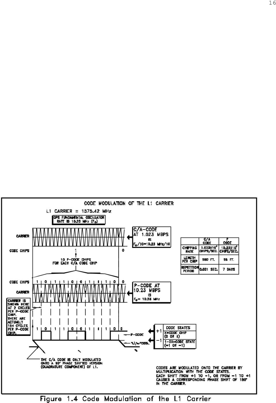
18 17 Even though both codes are broadcast on L1, they are distinguishable from one another by their transmission in quadrature. That means that the C/A code modulation on the L1 carrier is phase shifted 90 from the P code modulation on the same carrier. Pseudorange Point Positioning Remember the example of the four imaginary spheres? Well, this idea of having a replica to match to an incoming signal is popular. Not only do EDMs use it; the GPS receiver uses it too. A GPS receiver pulls out the copy a particular satellite s code and just keeps shifting it in time little by little until the two match up in order to find the transmission time of the signal. Actually lining up the code from the satellite with the replica in the GPS receiver is called autocorrelation, and depends on the transformation of code chips into code states. The formula used to derive code states (+1 and -1) from code chips (0 and 1) is: code state=1-2x where x is the code chip value. For example, a normal code state is +1, and corresponds to a code chip value of 0. A mirror code state is -1, and corresponds to a code chip value of 1. The function of these code states can be illustrated by asking two questions:

19 18 First, if a tracking loop of 10 code states generated in a receiver does not match 10 code states received from the satellite, how does the receiver know? In that case, the sum of the products of each of the receiver s 10 code states, with each of the 10 from the satellite, when divided by 10, does not equal 1. Secondly, how does the receiver know when a tracking loop of 10 replica code states does match 10 code states from the satellite? In that case the sum of the products of each code state of the receiver s replica 10, with each of the 10 from the satellite, divided by 10, is exactly 1. The autocorrelation function is: N 1 T 1 X(t)* X(t -τ )dt = X * 0 i X N N i = 1 i- j

20 X i* X i= i = 1 1 ( )= In Figure 1.5, before the code from the satellite and the replica from the receiver are matched:

21 20 the sum of the products of the code states is not 1. Following the correlation of the two codes: X i* X i= i = 1 1 ( ) = the sum of the code states is exactly 1, and the receiver s replica code fits the code from the satellite like a key fits a lock. That receiver is finding a pseudorange to that particular satellite when it does that, or as some folks say it is observing code-phase. So a pseudorange observable is based on a time shift. The Limitation of Pseudorange Point Positioning Pseudorange point positioning is the technique employed by inexpensive handheld GPS receivers. As I said at the top of this module it can yield positional accuracy of about ±20 to ±40 meters. The reasons for the relative inaccuracy are instructive because they affect all GPS. And it can be illustrated by the process of setting a watch from a time signal heard over a telephone. Imagine that a recorded voice said, "The time at the tone is 3 hours and 59 minutes, beep." If you set your watch the instant you heard that beep your watch would be wrong. Because the beep was broadcast at exactly 3 hours and 59 minutes, the moment you
22 21 heard it was later by precisely the amount of time it took the beep to travel to you through the telephone lines. In fact, you could measure the length of that telephone line, if you knew how long the beep was delayed, you could multiply by the speed of the light, and there you are. That s what the C/A code allows the receiver to do. It can calculate the range by calculating the approximately 1/17 th second delay from the moment the signal left the satellite to the moment it arrived by sliding the code from the satellite until it fits the replica code. But why is the result called a pseudorange, a false range? Ok, let s carry this telephone analogy farther. Instead of just setting your watch, suppose you decided to try to measure the length of the telephone line back to the master clock. So you get a clock just like the one they have. You take it down there and you synch them up. When you get home you call and get the voice, "The time at the tone is 9 hours and 33 minutes, beep." All right, but this time you can tell right away that the beep is late. That time has come and gone when you hear the beep. But now you can measure the difference between what your clock shows and the beeps from the master clock. All you have to do is set your replica clock back little by little until it matches the beeps and note how big the delay has to be. You multiply the delay by the speed of light; there s the distance. But what if your clock weren t perfect? What if your replica clock strayed a little after you synched it up and drove home? What if the master clock weren t perfect and its rate strayed a little too? What if the telephone lines weren t perfect and the beep got delayed a little bit? You get the idea. If the clocks can t be perfectly synchronized and if the propagation of the signal isn t perfect, then the calculated distance must be false. That s why it s called a pseudorange.
23 22 A Pseudorange Equation Ok, here s a formula presented by Langley in 1993 that neatly summarizes the errors that prevent a pseudorange from really being the true distance to a satellite. p = ρ+c(dt - dt)+d ion +d trop + ε p Where: p = ñ = c = dt = dt = the pseudorange measurement the true range. the speed of light the satellite clock error the receiver clock error d ion = ionospheric delay d trop = tropospheric delay å p = multipath, receiver noise and etc. Please note that the pseudorange, p, and the true range, ñ, cannot be made equivalent, without consideration of clock offsets, atmospheric effects and other biases that are inevitably present. In the next module, we ll talk about exactly where these errors come from and how they are mitigated to improve the accuracy of GPS positioning.
Yerkes Summer Institute 2002
 Before we begin our investigations into radio waves you should review the following material on your trip up to Yerkes. For some of you this will be a refresher, but others may want to spend more time
Timing Errors and Jitter
 Timing Errors and Jitter Background Mike Story In a sampled (digital) system, samples have to be accurate in level and time. The digital system uses the two bits of information the signal was this big
Post Processing Service
 Post Processing Service The delay of propagation of the signal due to the ionosphere is the main source of generation of positioning errors. This problem can be bypassed using a dual-frequency receivers
ACCESS CHARGE A fee charged subscribers or other telephone companies by a local exchange carrier for the use of its local exchange networks.
 Glossary of Telecommunications Terms (Source: Federal Communications Commission) ACCESS CHARGE A fee charged subscribers or other telephone companies by a local exchange carrier for the use of its local
EECC694 - Shaaban. Transmission Channel
 The Physical Layer: Data Transmission Basics Encode data as energy at the data (information) source and transmit the encoded energy using transmitter hardware: Possible Energy Forms: Electrical, light,
Robot Perception Continued
 Robot Perception Continued 1 Visual Perception Visual Odometry Reconstruction Recognition CS 685 11 Range Sensing strategies Active range sensors Ultrasound Laser range sensor Slides adopted from Siegwart
Collided Vehicle Position Detection using GPS & Reporting System through GSM
 Collided Vehicle Position Detection using GPS & Reporting System through GSM M.M.Raghaveendra 1, N.Sahitya 2, N.Nikhila 3, S.Sravani 4 1 Asst.Professor ECE Department, 2 Student, 3 Student, 4 Student,
Clocks/timers, Time, and GPS
 FYS3240 PC-based instrumentation and microcontrollers Clocks/timers, Time, and GPS Spring 2015 Lecture #11 Bekkeng, 22.12.2014 How good is a crystal oscillator (XO)? Interested in the long-term measurement
A New Radar Technology Broadband Radar Explained
 A New Radar Technology Broadband Radar Explained by Bill Johnson The landscape of small boat radar has just changed. Until two months ago, all the radars for the leisure marine market worked in pretty
:-------------------------------------------------------Instructor---------------------
 Yarmouk University Hijjawi Faculty for Engineering Technology Computer Engineering Department CPE-462 Digital Data Communications Final Exam: A Date: 20/05/09 Student Name :-------------------------------------------------------Instructor---------------------
CDMA TECHNOLOGY. Brief Working of CDMA
 CDMA TECHNOLOGY History of CDMA The Cellular Challenge The world's first cellular networks were introduced in the early 1980s, using analog radio transmission technologies such as AMPS (Advanced Mobile
Antennas & Propagation. CS 6710 Spring 2010 Rajmohan Rajaraman
 Antennas & Propagation CS 6710 Spring 2010 Rajmohan Rajaraman Introduction An antenna is an electrical conductor or system of conductors o Transmission - radiates electromagnetic energy into space o Reception
Understanding the Electrical Performance of Category Cables
 Understanding the Electrical Performance of Category Cables By: Mike Levesque, Mike Karg & Himmeler Themistocle Obsessed with cable solutions. Understanding the Electrical Performance of Category Cables
Computer Networks and Internets, 5e Chapter 6 Information Sources and Signals. Introduction
 Computer Networks and Internets, 5e Chapter 6 Information Sources and Signals Modified from the lecture slides of Lami Kaya (LKaya@ieee.org) for use CECS 474, Fall 2008. 2009 Pearson Education Inc., Upper
AM TRANSMITTERS & RECEIVERS
 Reading 30 Ron Bertrand VK2DQ http://www.radioelectronicschool.com AM TRANSMITTERS & RECEIVERS Revision: our definition of amplitude modulation. Amplitude modulation is when the modulating audio is combined
Math 215 Project (25 pts) : Using Linear Algebra to solve GPS problem
 : Using Linear Algebra to solve GPS problem") Due Thursday March 1, 2012 NAME(S): Math 215 Project (25 pts) : Using Linear Algebra to solve GPS problem 0.1 Introduction The age old question, Where in the world am I? can easily be solved nowadays by
Due Thursday March 1, 2012 NAME(S): Math 215 Project (25 pts) : Using Linear Algebra to solve GPS problem 0.1 Introduction The age old question, Where in the world am I? can easily be solved nowadays by
Implementation of Digital Signal Processing: Some Background on GFSK Modulation
 Implementation of Digital Signal Processing: Some Background on GFSK Modulation Sabih H. Gerez University of Twente, Department of Electrical Engineering s.h.gerez@utwente.nl Version 4 (February 7, 2013)
DIRECT TO HOME TELEVISION (DTH)
") DIRECT TO HOME TELEVISION (DTH) Today, most satellite TV customers in developed television markets get their programming through a direct broadcast satellite (DBS) provider, such as DISH TV or DTH platform.
DIRECT TO HOME TELEVISION (DTH) Today, most satellite TV customers in developed television markets get their programming through a direct broadcast satellite (DBS) provider, such as DISH TV or DTH platform.
Electromagnetic (EM) waves. Electric and Magnetic Fields. L 30 Electricity and Magnetism [7] James Clerk Maxwell (1831-1879)
![Electromagnetic (EM) waves. Electric and Magnetic Fields. L 30 Electricity and Magnetism [7] James Clerk Maxwell (1831-1879)](/thumbs/40/20813653.jpg "Electromagnetic (EM) waves. Electric and Magnetic Fields. L 30 Electricity and Magnetism [7] James Clerk Maxwell (1831-1879)") L 30 Electricity and Magnetism [7] ELECTROMAGNETIC WAVES Faraday laid the groundwork with his discovery of electromagnetic induction Maxwell added the last piece of the puzzle Heinrich Hertz made the experimental
L 30 Electricity and Magnetism [7] ELECTROMAGNETIC WAVES Faraday laid the groundwork with his discovery of electromagnetic induction Maxwell added the last piece of the puzzle Heinrich Hertz made the experimental
High Frequency Trading Turns to High Frequency Technology to Reduce Latency
 High Frequency Trading Turns to High Frequency Technology to Reduce Latency For financial companies engaged in high frequency trading, profitability depends on how quickly trades are executed. Now, new
Understanding SWR by Example
 Understanding SWR by Example Take the mystery and mystique out of standing wave ratio. Darrin Walraven, K5DVW It sometimes seems that one of the most mysterious creatures in the world of Amateur Radio
The Problem with Faxing over VoIP Channels
 The Problem with Faxing over VoIP Channels Lower your phone bill! is one of many slogans used today by popular Voice over IP (VoIP) providers. Indeed, you may certainly save money by leveraging an existing
INTRODUCTION TO COMMUNICATION SYSTEMS AND TRANSMISSION MEDIA
 COMM.ENG INTRODUCTION TO COMMUNICATION SYSTEMS AND TRANSMISSION MEDIA 9/6/2014 LECTURES 1 Objectives To give a background on Communication system components and channels (media) A distinction between analogue
CHAPTER 11 SATELLITE NAVIGATION
 CHAPTER 11 SATELLITE NAVIGATION INTRODUCTION 1100. Development The idea that led to development of the satellite navigation systems dates back to 1957 and the first launch of an artificial satellite into
(Refer Slide Time: 2:10)
") Data Communications Prof. A. Pal Department of Computer Science & Engineering Indian Institute of Technology, Kharagpur Lecture-12 Multiplexer Applications-1 Hello and welcome to today s lecture on multiplexer
Data Communications Prof. A. Pal Department of Computer Science & Engineering Indian Institute of Technology, Kharagpur Lecture-12 Multiplexer Applications-1 Hello and welcome to today s lecture on multiplexer
Germanium Diode AM Radio
 Germanium Diode AM Radio LAB 3 3.1 Introduction In this laboratory exercise you will build a germanium diode based AM (Medium Wave) radio. Earliest radios used simple diode detector circuits. The diodes
Doppler. Doppler. Doppler shift. Doppler Frequency. Doppler shift. Doppler shift. Chapter 19
 Doppler Doppler Chapter 19 A moving train with a trumpet player holding the same tone for a very long time travels from your left to your right. The tone changes relative the motion of you (receiver) and
Phase coherency of CDMA caller location processing based on TCXO frequency reference with intermittent GPS correction
 Phase coherency of CDMA caller location processing based on TCXO frequency reference with intermittent GPS correction Dingchen Lu, Alfredo Lopez, Surendran K. Shanmugam, John Nielsen and Gerard Lachapelle
Data Transmission. Data Communications Model. CSE 3461 / 5461: Computer Networking & Internet Technologies. Presentation B
 CSE 3461 / 5461: Computer Networking & Internet Technologies Data Transmission Presentation B Kannan Srinivasan 08/30/2012 Data Communications Model Figure 1.2 Studying Assignment: 3.1-3.4, 4.1 Presentation
Homebuilt HF Radios for Use Underground Paul R. Jorgenson KE7HR
 Homebuilt HF Radios for Use Underground Paul R. Jorgenson KE7HR With the good success in using Amateur Band HF radio for underground communications, I started looking for cheaper alternatives to the $500+
Unit of Learning # 2 The Physical Layer. Redes de Datos Sergio Guíñez Molinos sguinez@utalca.cl 1-2009
 Unit of Learning # 2 The Physical Layer Redes de Datos Sergio Guíñez Molinos sguinez@utalca.cl 1-2009 The Theoretical Basis for Data Communication Sergio Guíñez Molinos Redes de Computadores 2 The Theoretical
Clock Recovery in Serial-Data Systems Ransom Stephens, Ph.D.
 Clock Recovery in Serial-Data Systems Ransom Stephens, Ph.D. Abstract: The definition of a bit period, or unit interval, is much more complicated than it looks. If it were just the reciprocal of the data
Analog vs. Digital Transmission
 Analog vs. Digital Transmission Compare at two levels: 1. Data continuous (audio) vs. discrete (text) 2. Signaling continuously varying electromagnetic wave vs. sequence of voltage pulses. Also Transmission
HANDBOOK. Measuring System DESIGN EDITORS PETER H. SYDENHAM RICHARD THORN ARTICLE OFFPRINT
 HANDBOOK OF Measuring System DESIGN EDITORS PETER H. SYDENHAM RICHARD THORN ARTICLE OFFPRINT 200: Calibrations and Standards in Time Measurement Michael A. Lombardi National Institute of Standards and
CDMA Technology : Pr. S. Flament www.greyc.fr/user/99. Pr. Dr. W. sk www.htwg-konstanz.de. On line Course on CDMA Technology
 CDMA Technology : Pr. Dr. W. sk www.htwg-konstanz.de Pr. S. Flament www.greyc.fr/user/99 On line Course on CDMA Technology CDMA Technology : CDMA / DS : Principle of operation Generation of PN Spreading
CHAPTER 18 TIME TIME IN NAVIGATION
 CHAPTER 18 TIME TIME IN NAVIGATION 1800. Solar Time The Earth s rotation on its axis causes the Sun and other celestial bodies to appear to move across the sky from east to west each day. If a person located
Selecting Receiving Antennas for Radio Tracking
 Selecting Receiving Antennas for Radio Tracking Larry B Kuechle, Advanced Telemetry Systems, Inc. Isanti, Minnesota 55040 lkuechle@atstrack.com The receiving antenna is an integral part of any radio location
A pulse is a collection of cycles that travel together. the cycles ( on or transmit time), and. the dead time ( off or receive time)
, and. the dead time ( off or receive time)") chapter 2 Pulsed Ultrasound In diagnostic ultrasound imaging, short bursts, or pulses, of acoustic energy are used to create anatomic images. Continuous wave sound cannot create anatomic images. Analogy
chapter 2 Pulsed Ultrasound In diagnostic ultrasound imaging, short bursts, or pulses, of acoustic energy are used to create anatomic images. Continuous wave sound cannot create anatomic images. Analogy
Public Switched Telephone System
 Public Switched Telephone System Structure of the Telephone System The Local Loop: Modems, ADSL Structure of the Telephone System (a) Fully-interconnected network. (b) Centralized switch. (c) Two-level
Application Note Receiving HF Signals with a USRP Device Ettus Research
 Application Note Receiving HF Signals with a USRP Device Ettus Research Introduction The electromagnetic (EM) spectrum between 3 and 30 MHz is commonly referred to as the HF band. Due to the propagation
A: zero everywhere. B: positive everywhere. C: negative everywhere. D: depends on position.
 A string is clamped at both ends and then plucked so that it vibrates in a standing wave between two extreme positions a and c. (Let upward motion correspond to positive velocities.) When the
Motion & The Global Positioning System (GPS)
") Grade Level: K - 8 Subject: Motion Prep Time: < 10 minutes Duration: 30 minutes Objective: To learn how to analyze GPS data in order to track an object and derive its velocity from positions and times.
Grade Level: K - 8 Subject: Motion Prep Time: < 10 minutes Duration: 30 minutes Objective: To learn how to analyze GPS data in order to track an object and derive its velocity from positions and times.
High Speed and Voice over I.P September 1, 2005
 If your property is setup with high-speed Internet access, you can incur big savings on your outgoing calls by using Voice over I.P. services to replace your local telephone and/or long distance service.
Clocking. Clocking in the Digital Network
 Clocking Clocking in the Digital Network Stratum Levels Clocking Distribution Single Point versus Multiple Points Timing Differences Correcting Timing Errors Buffers 1 Clocking The most important aspect
Computer Time Synchronization
 Michael Lombardi Time and Frequency Division National Institute of Standards and Technology Computer Time Synchronization The personal computer revolution that began in the 1970's created a huge new group
Digital Modulation. David Tipper. Department of Information Science and Telecommunications University of Pittsburgh. Typical Communication System
 Digital Modulation David Tipper Associate Professor Department of Information Science and Telecommunications University of Pittsburgh http://www.tele.pitt.edu/tipper.html Typical Communication System Source
Talking Atomic Alarm Clock Instructions
 1 Talking Atomic Alarm Clock Instructions S1 (Talking+Snooze+Back Light) S2 (Alarm Time + Alarm Hour) S4 (Alarm Volume + OFF) S3 (Alarm ON/OFF + Alarm Minute) S5 (Wave, Manual Signal Reception) S8 (DST
Technician Licensing Class. Lesson 1. presented by the Arlington Radio Public Service Club Arlington County, Virginia
 Technician Licensing Class Lesson 1 presented by the Arlington Radio Public Service Club Arlington County, Virginia 1 FCC Rules Sub element T1 2 Why Amateur Radio? The basis & purpose of the amateur service
Sound System Buying Guide
 Sound System Buying Guide The Guide format is like an FAQ (frequently asked questions), with the answers taken together forming a great basis for picking your favorite components. With this information,
VE3MLB Phased Double V Antenna for 75/80 Meter Band
 Jan. 17, 2008 VE3MLB Phased Double V Antenna for 75/80 Meter Band This is a story of a double inverted V antenna that I built in January 2008. I already had a full 80 meter Delta loop suspended from my
After a wave passes through a medium, how does the position of that medium compare to its original position?
 Light Waves Test Question Bank Standard/Advanced Name: Question 1 (1 point) The electromagnetic waves with the highest frequencies are called A. radio waves. B. gamma rays. C. X-rays. D. visible light.
Lecture 3: Signaling and Clock Recovery. CSE 123: Computer Networks Stefan Savage
 Lecture 3: Signaling and Clock Recovery CSE 123: Computer Networks Stefan Savage Last time Protocols and layering Application Presentation Session Transport Network Datalink Physical Application Transport
UNDERSTANDING RADIO FREQUENCY AND BC HYDRO S SMART METERS
 UNDERSTANDING RADIO FREQUENCY AND BC HYDRO S SMART METERS SUMMARY Radio frequency (RF) technology has been around for over years and is a part of everyday life radios, TVs and medic alert systems are examples.
Waveforms and the Speed of Sound
 Laboratory 3 Seth M. Foreman February 24, 2015 Waveforms and the Speed of Sound 1 Objectives The objectives of this excercise are: to measure the speed of sound in air to record and analyze waveforms of
Trigonometric functions and sound
 Trigonometric functions and sound The sounds we hear are caused by vibrations that send pressure waves through the air. Our ears respond to these pressure waves and signal the brain about their amplitude
THE STATISTICAL TREATMENT OF EXPERIMENTAL DATA 1
 THE STATISTICAL TREATMET OF EXPERIMETAL DATA Introduction The subject of statistical data analysis is regarded as crucial by most scientists, since error-free measurement is impossible in virtually all
6.025J Medical Device Design Lecture 3: Analog-to-Digital Conversion Prof. Joel L. Dawson
 Let s go back briefly to lecture 1, and look at where ADC s and DAC s fit into our overall picture. I m going in a little extra detail now since this is our eighth lecture on electronics and we are more
CHARACTERISTICS OF RADIO
 MODULE - 3 Characteristics of 9 CHARACTERISTICS OF RADIO You probably know the story of Sanjay in the Mahabharata who described the war to Dritharasthtra who could not see. Sanjay could see the war with
DUFF DUFF. Software Defined Radio Direction Finding. Balint Seeber, Applications Engineer balint@ettus.com @spenchdotnet
 DUFF DUFF Software Defined Radio Direction Finding Balint Seeber, Applications Engineer balint@ettus.com @spenchdotnet Notes and links in PDF comments on each slide DF Usage Radio navigation Predecessor
Wireless Phones, GPS and Data Applications
 Wireless Phones, GPS and Data Applications James M. Conrad and Santosh Kolenchery Ericsson, Inc., 7001 Development Drive, Research Triangle Park, NC 27709 (919) 472-6178, james.conrad@ericsson.com (919)
Copyright 2008 Pearson Education, Inc., publishing as Pearson Addison-Wesley.
 Chapter 20. Traveling Waves You may not realize it, but you are surrounded by waves. The waviness of a water wave is readily apparent, from the ripples on a pond to ocean waves large enough to surf. It
CS263: Wireless Communications and Sensor Networks
 CS263: Wireless Communications and Sensor Networks Matt Welsh Lecture 4: Medium Access Control October 5, 2004 2004 Matt Welsh Harvard University 1 Today's Lecture Medium Access Control Schemes: FDMA TDMA
Remote Calibration of a GPS Timing Receiver to UTC(NIST) via the Internet*
 via the Internet*") Remote Calibration of a GPS Timing Receiver to UTC(NIST) via the Internet* Michael A. Lombardi and Andrew N. Novick National Institute of Standards and Technology Boulder, Colorado lombardi@boulder.nist.gov
Remote Calibration of a GPS Timing Receiver to UTC(NIST) via the Internet* Michael A. Lombardi and Andrew N. Novick National Institute of Standards and Technology Boulder, Colorado lombardi@boulder.nist.gov
1.264 Lecture 32. Telecom: Basic technology. Next class: Green chapter 4, 6, 7, 10. Exercise due before class
 1.264 Lecture 32 Telecom: Basic technology Next class: Green chapter 4, 6, 7, 10. Exercise due before class 1 Exercise 1 Communications at warehouse A warehouse scans its inventory with RFID readers that
Vehicle data acquisition using CAN By Henning Olsson, OptimumG henning.olsson@optimumg.com
 Vehicle data acquisition using By Henning Olsson, OptimumG henning.olsson@optimumg.com Introduction: Data acquisition is one of the best tools to increase the understanding of vehicle behavior. One can
Physics in Entertainment and the Arts
 Physics in Entertainment and the Arts Chapter VII Wave Transfer and Waves incident on a rigid boundary almost completely reflect Almost all the wave s energy is reflected back the way it came Waves incident
Hello viewers, welcome to today s lecture on cellular telephone systems.
 Data Communications Prof. A. Pal Department of Computer Science & Engineering Indian Institute of Technology, Kharagpur Lecture minus 31 Cellular Telephone Systems Hello viewers, welcome to today s lecture
GENERAL INFORMATION ON GNSS AUGMENTATION SYSTEMS
 GENERAL INFORMATION ON GNSS AUGMENTATION SYSTEMS 1. INTRODUCTION Navigation technologies with precision approach and landing systems, for civilian and military purposes, enable aircrafts to perform their
www.fmtalkinghouse.com
 www.fmtalkinghouse.com 24x7 FM Announcement System (Talking Sign) 2009 FM TALKING HOUSE All rights reserved Talking Sign 24x7 FM Announcement System Description: The 24x7 FM Announcement System or Talking
15-441: Computer Networks Homework 1
 15-441: Computer Networks Homework 1 Assigned: January 29, 2008 Due: February 7, 2008 1. Suppose a 100-Mbps point-to-point link is being set up between Earth and a new lunar colony. The distance from the
A) F = k x B) F = k C) F = x k D) F = x + k E) None of these.
 F = k x B) F = k C) F = x k D) F = x + k E) None of these.") CT16-1 Which of the following is necessary to make an object oscillate? i. a stable equilibrium ii. little or no friction iii. a disturbance A: i only B: ii only C: iii only D: i and iii E: All three Answer:
CT16-1 Which of the following is necessary to make an object oscillate? i. a stable equilibrium ii. little or no friction iii. a disturbance A: i only B: ii only C: iii only D: i and iii E: All three Answer:
Real Time Tracking In Wireless Network Using Gps/Avl
 Real Time Tracking In Wireless Network Using Gps/Avl M. Satheesh Kumar Saveetha University Abstract: The Paper entitled as Real Time Tracking in Wireless Network Using GPS/AVL. The main Objective of this
GPS Based Low Cost Intelligent Vehicle Tracking System (IVTS)
") 2012 International Conference on Traffic and Transportation Engineering (ICTTE 2012) IPCSIT vol. 26 (2012) (2012) IACSIT Press, Singapore GPS Based Low Cost Intelligent Vehicle Tracking System (IVTS) Dr.
2012 International Conference on Traffic and Transportation Engineering (ICTTE 2012) IPCSIT vol. 26 (2012) (2012) IACSIT Press, Singapore GPS Based Low Cost Intelligent Vehicle Tracking System (IVTS) Dr.
Application Note Noise Frequently Asked Questions
 : What is? is a random signal inherent in all physical components. It directly limits the detection and processing of all information. The common form of noise is white Gaussian due to the many random
The front end of the receiver performs the frequency translation, channel selection and amplification of the signal.
 Many receivers must be capable of handling a very wide range of signal powers at the input while still producing the correct output. This must be done in the presence of noise and interference which occasionally
Distributed Systems Theory 6. Clock synchronization - logical vs. physical clocks. November 9, 2009
 Distributed Systems Theory 6. Clock synchronization - logical vs. physical clocks November 9, 2009 1 Synchronization: single CPU sys vs. dist sys. Single CPU: DS: critical regions, mutual exclusion, and
EE4367 Telecom. Switching & Transmission. Prof. Murat Torlak
 Path Loss Radio Wave Propagation The wireless radio channel puts fundamental limitations to the performance of wireless communications systems Radio channels are extremely random, and are not easily analyzed
ANALYZER BASICS WHAT IS AN FFT SPECTRUM ANALYZER? 2-1
 WHAT IS AN FFT SPECTRUM ANALYZER? ANALYZER BASICS The SR760 FFT Spectrum Analyzer takes a time varying input signal, like you would see on an oscilloscope trace, and computes its frequency spectrum. Fourier's
E190Q Lecture 5 Autonomous Robot Navigation
 E190Q Lecture 5 Autonomous Robot Navigation Instructor: Chris Clark Semester: Spring 2014 1 Figures courtesy of Siegwart & Nourbakhsh Control Structures Planning Based Control Prior Knowledge Operator
T = 1 f. Phase. Measure of relative position in time within a single period of a signal For a periodic signal f(t), phase is fractional part t p
, phase is fractional part t p") Data Transmission Concepts and terminology Transmission terminology Transmission from transmitter to receiver goes over some transmission medium using electromagnetic waves Guided media. Waves are guided
Data Transmission Concepts and terminology Transmission terminology Transmission from transmitter to receiver goes over some transmission medium using electromagnetic waves Guided media. Waves are guided
1 Multi-channel frequency division multiplex frequency modulation (FDM-FM) emissions
 emissions") Rec. ITU-R SM.853-1 1 RECOMMENDATION ITU-R SM.853-1 NECESSARY BANDWIDTH (Question ITU-R 77/1) Rec. ITU-R SM.853-1 (1992-1997) The ITU Radiocommunication Assembly, considering a) that the concept of necessary
Rec. ITU-R SM.853-1 1 RECOMMENDATION ITU-R SM.853-1 NECESSARY BANDWIDTH (Question ITU-R 77/1) Rec. ITU-R SM.853-1 (1992-1997) The ITU Radiocommunication Assembly, considering a) that the concept of necessary
GPS Options & Project Planning for Enterprise Mobile Computing
 OrbitGPS White Paper GPS Options & Project Planning for Enterprise Mobile Computing 2008 OrbitGPS LLC. All Rights Reserved. Product names mentioned in this manual may be trademarks or registered trademarks
Broadband Networks. Prof. Dr. Abhay Karandikar. Electrical Engineering Department. Indian Institute of Technology, Bombay. Lecture - 29.
 Broadband Networks Prof. Dr. Abhay Karandikar Electrical Engineering Department Indian Institute of Technology, Bombay Lecture - 29 Voice over IP So, today we will discuss about voice over IP and internet
DT3: RF On/Off Remote Control Technology. Rodney Singleton Joe Larsen Luis Garcia Rafael Ocampo Mike Moulton Eric Hatch
 DT3: RF On/Off Remote Control Technology Rodney Singleton Joe Larsen Luis Garcia Rafael Ocampo Mike Moulton Eric Hatch Agenda Radio Frequency Overview Frequency Selection Signals Methods Modulation Methods
Chapter 19 Operational Amplifiers
 Chapter 19 Operational Amplifiers The operational amplifier, or op-amp, is a basic building block of modern electronics. Op-amps date back to the early days of vacuum tubes, but they only became common
Chap 4 Circuit-Switching Networks
 hap 4 ircuit-switching Networks Provide dedicated circuits between users Example: 1. telephone network: provides 64Kbps circuits for voice signals 64Kbps=8 k samples/sec * 8 bits/sample 2. transport network:
CHAPTER 4. Electromagnetic Spectrum
 ELEC4504 Avionics Systems 9 CHAPTER 4. Electromagnetic Spectrum 4.1. Electromagnetic (EM) Waves In free space (or the atmosphere) the electric field is perpendicular to the magnetic field and both are
MAINTENANCE & ADJUSTMENT
 MAINTENANCE & ADJUSTMENT Circuit Theory The concept of PLL system frequency synthesization is not of recent development, however, it has not been a long age since the digital theory has been couplet with
What TV Ratings Really Mean
 What TV Ratings Really Mean You just heard that a TV Show was ranked #1 in the Nielsen Media Research ratings. What does that really mean? How does Nielsen Media Research "rate" TV shows? Why do shows
 IMES (Indoor Messaging System) A Proposal for New Indoor Positioning System Presenter: Dr. Dinesh Manandhar GNSS Technologies Inc., Japan Third Meeting of the International Committee on Global Navigation
COLLATED QUESTIONS: ELECTROMAGNETIC RADIATION
 COLLATED QUESTIONS: ELECTROMAGNETIC RADIATION 2011(2): WAVES Doppler radar can determine the speed and direction of a moving car. Pulses of extremely high frequency radio waves are sent out in a narrow
General GPS Antenna Information APPLICATION NOTE
 General GPS Antenna Information APPLICATION NOTE General GPS Antenna Information Global Positioning System and Precise Time & Frequency The Global Positioning System (GPS) is a worldwide radio-navigation
Sampling Theorem Notes. Recall: That a time sampled signal is like taking a snap shot or picture of signal periodically.
 Sampling Theorem We will show that a band limited signal can be reconstructed exactly from its discrete time samples. Recall: That a time sampled signal is like taking a snap shot or picture of signal
Antenna Properties and their impact on Wireless System Performance. Dr. Steven R. Best. Cushcraft Corporation 48 Perimeter Road Manchester, NH 03013
 Antenna Properties and their impact on Wireless System Performance Dr. Steven R. Best Cushcraft Corporation 48 Perimeter Road Manchester, NH 03013 Phone (603) 627-7877 FAX: (603) 627-1764 Email: sbest@cushcraft.com
Speed bump. Acceleration-ramp blues on the information superhighway
 Speed bump Acceleration-ramp blues on the information superhighway The signs on the Infobahn say, Full Speed Ahead... but some bumps in the road might send unlucky travelers hurtling off the edge and into
Vehicle Scrutinizing using GPS & GSM Technologies Implemented with Ardunio controller
 Vehicle Scrutinizing using GPS & GSM Technologies Implemented with Ardunio controller A.Kalaiarasi 1, Raviram.P 2, Prabakaran. P M 3, ShanthoshKumar.K 4, Dheeraj B P 5 Assistant Professor, Dept. of EEE,
Physics 202 Problems - Week 8 Worked Problems Chapter 25: 7, 23, 36, 62, 72
 Physics 202 Problems - Week 8 Worked Problems Chapter 25: 7, 23, 36, 62, 72 Problem 25.7) A light beam traveling in the negative z direction has a magnetic field B = (2.32 10 9 T )ˆx + ( 4.02 10 9 T )ŷ
Instructions for - Installation of Satellite Channels
 ENGLISH Instructions for - Installation of Satellite Channels Updated: March 2011 Experience Reality AQUOS LCD-TVs Spring/Summer 2011 Page - 1 - LE820 - LE822 - LE814 - LE824 - LE914 - LE925 Contents:
Analog and Digital Signals, Time and Frequency Representation of Signals
 1 Analog and Digital Signals, Time and Frequency Representation of Signals Required reading: Garcia 3.1, 3.2 CSE 3213, Fall 2010 Instructor: N. Vlajic 2 Data vs. Signal Analog vs. Digital Analog Signals
CARLETON UNIVERSITY Department of Systems and Computer Engineering. SYSC4700 Telecommunications Engineering Winter 2014. Term Exam 13 February 2014
 CARLETON UNIVERSITY Department of Systems and Computer Engineering SYSC4700 Telecommunications Engineering Winter 2014 Term Exam 13 February 2014 Duration: 75 minutes Instructions: 1. Closed-book exam