Beachcomber Hot Tubs Owner s Manual
|
|
|
- Steven Wilkerson
- 8 years ago
- Views:
Transcription
1 Beachcomber Hot Tubs Owner s Manual

2 Table of Contents Safety Instructions Beachcomber Safety Features Starting up a Beachcomber Hot Tub Water Care Product Startup Procedure Equipment Configuration Diagrams Digital Systems Programming and operation Series Digital 1000 System (160 included) Series Digital 2000 System Series Digital 3000 System Model 320M and 320 XM Mechanical Systems Water Care and Maintenance Beachcomber Hot Tub care and Maintenance Operation of Beachcomber Hot Tub Interior features Draining a Beachcomber Hot Tub Vacation Instructions Winter Operation Information Shut Down Procedures Do s and Don ts Water Quality Troubleshooting Guide Beachcomber Hot Tub Care and Maintenance Record Beachcomber Hot Tub Model # Details Chart

3 IMPORTANT SAFETY INSTRUCTIONS IMPORTANT! READ AND FOLLOW ALL INSTRUCTIONS. A green colored terminal (or wire connector marked "Ground") is provided within the control box. To reduce the risk of electric shock, connect this terminal or connector to the grounding terminal of the electric service or supply panel with a continuous copper wire equivalent in size to the circuit conductors supplying this equipment. In addition bonding lugs are provided and marked "Bonding Lugs". To reduce the risk of electric shock, connect the bonding lugs in accordance with the local electric code. At least two lugs marked "BONDING LUGS" are provided on the external surface of the supply terminal box. To reduce the risk of electrical shock connect the local common binding grid in the area of the hot tub to these terminals with an insulated or bare copper conductor not smaller than No.6 AWG. (Note: this is pre done at the factory) All field-installed metal components such as rails, ladders, drains or other similar hardware within 10 ft. (3m) of the hot tub shall be bonded to the equipment grounding bus with copper conductors not smaller than #6AWG. CAUTION: WIRING CONNECTED IN THIS BOX MUST BE RATED AT 600V. Do not attempt to fix any thing within the management system. The high voltage can cause injury or death. The tub must be hooked up to a G.F.C.I. (ground fault circuit interrupter) by a licensed electrician. Use the test button on your G.F.C.I. monthly to ensure it is working properly. Always make sure there is an adequate sanitizer level in your tub before entering. Failure to do so may cause skin irritations or illness. Use a test kit or test strips to check. CAUTION: WATER TEMPERATURE IN EXCESS OF 100ºF/38ºC MAY BE INJURIOUS TO YOUR HEALTH To reduce the risk of drowning from hair and body entrapment, install suction fitting(s) with a marked flow rate that is not less than the flow rate marked on the remote packaged unit.(note: these are factory installed). Do not operate the tub with any of the suction fitting covers off. These covers are there to prevent hair or objects from being sucked into the plumbing. See Figure 1. Figure 1 CAUTION: THE EQUIPMENT AND CONTROLS SHALL BE LOCATED NOT LESS THAN 3.5ft. / (1 m) HORIZONTALLY FROM THE hot tub. HYPERTHERMIA occurs when the internal temperature of the body reaches a level of several degrees above normal body temperature of 98.6ºF (37ºC).The symptoms of hyperthermia include drowsiness, lethargy and an increase of internal temperature of the body. THE EFFECTS: unawareness of impending hazard; failure to perceive heat; failure to recognize the need to exit the hot tub physical inability to exit hot tub fetal damage in pregnant women. Unconsciousness and danger of drowning. WARNING: THE USE OF ALCOHOL OR DRUGS CAN GREATLY INCREASE THE RISK OF FATAL HYPER- THERMIA IN HOT TUBS. Recommended time in water at 100ºF/38ºC is 15 minutes. Lower temperatures will permit longer bathing times. Always check the temperature of the water before entry.

4 Warning: Any person with the following conditions should consult their Physician before using a hot tub. Diabetes, High blood pressure, Heart disease, Circulatory problems, Pregnant women or those taking medication prescribed by their Physician. Do not allow electrical devices to such as portable stereos, TVs, hair dryers within 5 feet/1.5 meters of the tub. Failure to do so could result in death due to electrocution should the device fall in the water. Warning: Always provide adequate supervision when children are using the hot tub Always follow instructions on Chemicals closely. Add one at a time Measure accurately Add chemical to water not water to chemicals. Store chemicals in a cool dry place, do not allow liquids to freeze. Do not mix products together. BEACHCOMBER S SAFETY FEATURES Molded Interior Steps Beachcomber hot tubs are made with checker plate flooring designed to make entry and exit safer. Molded Side Hand Grips Found on all sides of a Beachcomber hot tub, these hand grips make getting out of the seat much easier and safer. See Figure 2. Figure 2 Protec Step (optional feature) If your hot tub is equipped with the Beachcomber Protec option, it includes the Protec Safety step to make entry and exit of the hot tub easier and safer. Always secure the step to the hot tub with the hardware provided to ensure maximum safety and protection to the Protec Equipment. Portable Step (optional feature) With Beachcomber s Original Portable Hot Tub, you can purchase an optional two level step for easy entry and exit. Heatshield Cover Locks To prevent unwanted entry by children or unauthorized users, use the cover lock assemblies that come as a standard feature with each hot tub. Screw the female half on to the hot tub skirting with the stainless screws provided. See Figure 3. Figure 3 STARTING UP A BEACHCOMBER HOT TUB Once the Protec equipment is hooked up, using the separate instructions provided in the Protec Equipment box and the electrical connection is made by a qualified electrician, do the following: 1. Check all union fittings on the Protec and Portable equipment to ensure that they are tight. Hand tight is sufficient. If leaking is noted at these fittings you may need to tighten further or the gasket may be missing or not seated properly. Unscrew the union and check if this is suspected. 2. Open all knife valves (see Figure 4) that are pointing up. Leave all valves that are facing down closed. Fill the hot tub with water from a garden hose. You can hang the hose over the edge of the hot tub or hook it up to the black drain/fill valve located down by the pumps and fill from the bottom. Allow some water to run out of the drain fitting to release any potential stagnant water Figure 4

5 3. Fill the hot tub to half way up the skimmer opening. Note: If your hot tub is Hush Pump equipped your level can be lowered to one third up the skimmer opening. This will allow for more displacement if the hot tub is subjected to use by more than the recommended amount of people for that model. See Figure 5. Figure 5 WARNING! Over filling will not allow room for displacement from people entering the hot tub. Under filling could cause an airlock in the system and could lead to pump and heater damage not covered by your guarantee. 4. Open the air bleed knobs to release any air trapped in the external plumbing. There is one on the 300 and 500 series hot tubs, two on a 500 series with Hush pump and a standard 700 series and three on a 700 series with Hush pump. Once all air is bled from the system, open any knife valves that are facing down. See Figure Turn on your GFCI breaker. The circulation pump will come on and the heater light or icon will come on. If the fill water is colder than 50ºF / 10ºC, the pump(s) will go to high speed for 30 seconds, then back to low speed, then the heater will come on. Now that the hot tub is up and running and the heater is on you need to check the settings and possibly change them to suit your individual needs. The default set temperature on all hot tubs is 100ºF / 37ºC. On 300 series Digital systems, the only setting you can adjust is the temperature. On 500 series, you can adjust the temperature and the amount of hours the hot tub filters, as well as how many times a day the filter hours occur. On 700 series, you can adjust temperature, amount of hours the hot tub filters and a time clock that needs to be set to your local time so the system knows when to run the filter times. Note: In the event of a power outage, the 300 and 500 series will default back to the factory filter and temperature settings. On 700 series the settings are backed up for 30 days and you will not have to reset once power is back on. Note: 700 series hot tubs with Hush Pump, the Hush Pump will not resume 24 hour filtration until the start of the next filter cycle. You can advance the time clock 24 hrs if you do not want to wait until the start of the next filter cycle. WATER CARE PRODUCT STARTUP PROCEDURE Follow these basic steps before entering the hot tub. Add a full bottle of Eliminate #1. Wait one hour. Add 2 oz/60 ml of Eliminate Plus #2. Add 3.5 oz/100 ml of Purezyme #3. Wait 6 hours. Add your sanitizer of choice. Please note: Beachcomber offers several water care programs to suit your needs; ask your dealer for a tote card for those specific details - your startup regimen may vary slightly. Beachcomber recommends the following parameters for hot tub water: ph Level Sanitizer level (chlorine or bromine) 3-5 ppm Calcium Hardness ppm Total Alkalinity Total Dissolved Solids not more than 1500 ppm Your dealer may recommend slightly different levels depending on your local source water. Please see your dealer for more information by taking a water sample in to be analyzed, or, check our website at:

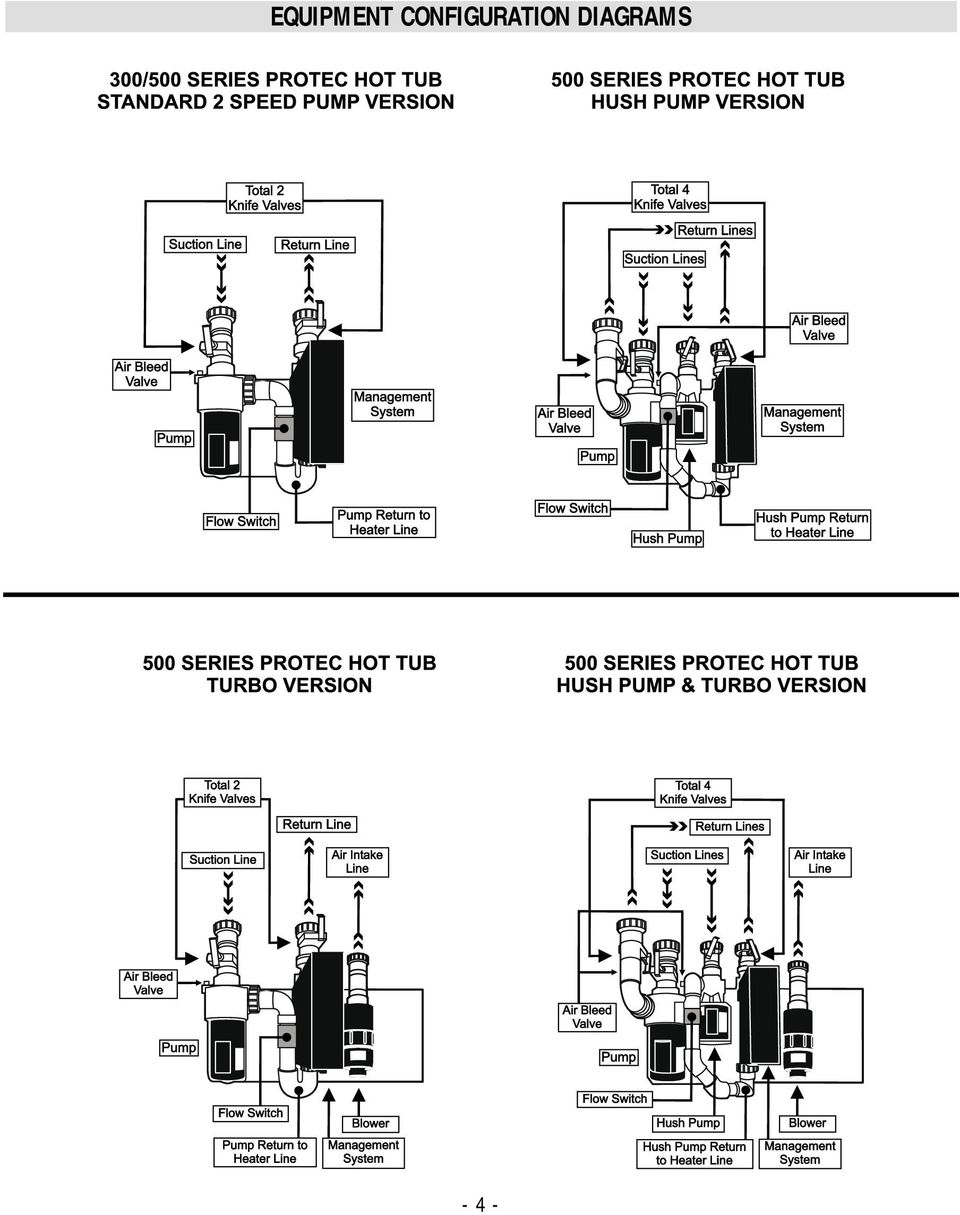
6 EQUIPMENT CONFIGURATION DIAGRAMS - 4 -
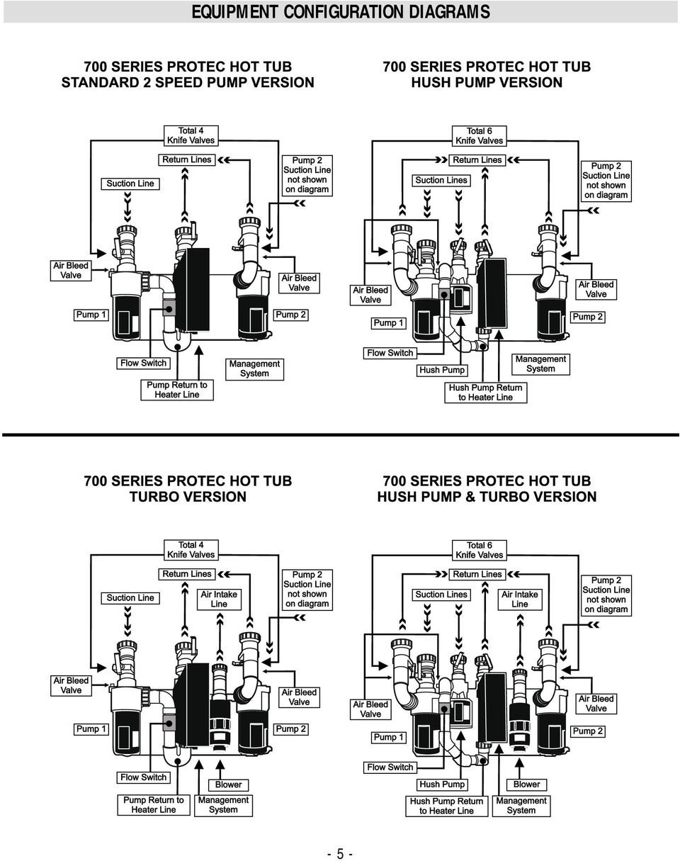
7 EQUIPMENT CONFIGURATION DIAGRAMS - 5 -
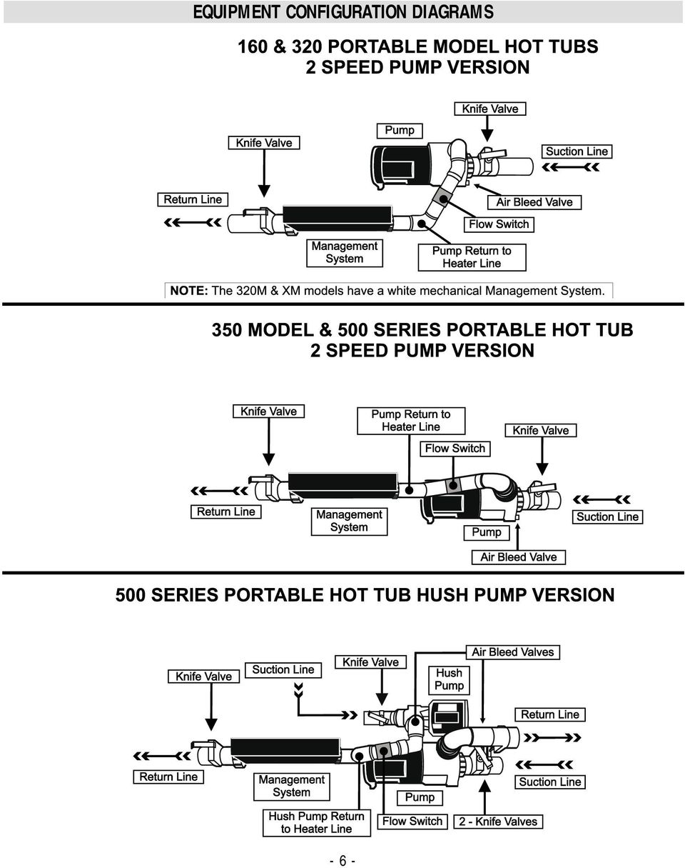
8 EQUIPMENT CONFIGURATION DIAGRAMS - 6 -
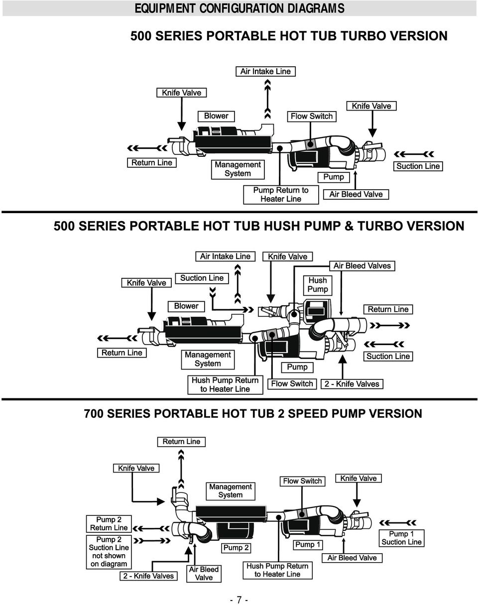
9 EQUIPMENT CONFIGURATION DIAGRAMS - 7 -
10 EQUIPMENT CONFIGURATION DIAGRAMS - 8 -

11 DIGITAL SYSTEMS, PROGRAMMING, OPERATION AND ERROR MESSAGES 300 Series Digital 1000 System including Model 160 START UP When your hot tub is first powered up, it will automatically heat and maintain 100 F / 37.5 C until you change the set temperature. TEMPERATURE ADJUSTMENT (60 F-104 F) / (16 C-40 C) Press the pad to display the temperature previously set. This set temperature is flashed on the display. In a few seconds, the numbers will stop flashing, and the display will show the actual temperature. Pressing the pad a second time will cause the set temperature to increase or decrease depending on what direction was last chosen. Each press to follow will change the set temperature in the same direction. If the opposite direction is desired release the pad and let the display revert to the actual water temperature. Press the pad to display the set temperature, and again to make the temperature change in the desired direction. Actual water temperature will reappear on the display after changing the temperature setting. LIGHT/MASSAGE Press the pad to cycle through the light and jets features. The operating sequence is as follows: 1) low-speed pump, 2) low-speed pump and light, 3) high-speed pump and light, 4) high-speed pump only, and 5) off. The low-speed pump automatically turns off after 1 hour. The high-speed pump stops after 15 minutes. The light turns off after 2 hours of use PRESET FILTER CYCLES Your hot tub is set to filter itself twice a day. The first filter cycle will start one minute after the hot tub is powered up. The second filter cycle will begin twelve hours after the start of the first filter cycle. Filter cycle duration is 2 or 6 hours long, and is set at the time of delivery. During filtration, the low-speed pump and ozone generator (if installed) will run. Contact your local dealer to change the cycle. STANDBY MODE Press then within 3 seconds to prevent the hot tub from operating at any time. "Sb" will appear on the display. Standby mode should be used when removing or replacing the filter. All hot tub functions will be disabled except for freeze control. Press any button to resume hot tub operation. Do not use stand-by for draining and refilling; shut off the power at your breaker panel. DISPLAY MESSAGES "OH" "Overheat" - The hot tub has shut down. Either the water has reached 112 F / 44 C, or the high limit sensor has detected 118 F / 48 C at the heater. DO NOT ENTER THE WATER. Remove the hot tub cover and allow water to cool. At 110 F / 43 C, the hot tub should automatically reset. If the hot tub does not reset, then turn off all power to the hot tub and contact your dealer or service organization.

12 "FL" "Flow" (Flashing) Flow of water is inhibited. Check and open any closed knife valves. Check for correct water level. Clean or replace your Microfilter. "FL" "Flow" (Not flashing) - Flow switch has malfunctioned. Contact your dealer or service organization. "Sn" "Sensor" - Hot tub is shut down. The high-limit or water temperature sensor is not working. Contact your dealer or service organization. "Sb" "Standby" - Hot tub is in standby mode. All hot tub functions are disabled except for freeze control. Press any panel button to resume operation. Heat Light Flashing "Summer Standby Mode" Filtering has stopped: water temperature is 3 F / 1.5 C or more above set point after 3 hours of a filter cycle. If water cools to 1ºF / 0.5ºC above set temperature and the system is still in filter mode, filtering will resume

13 DIGITAL SYSTEMS, PROGRAMMING, OPERATION AND ERROR MESSAGES 500 Series Digital 2000 System START UP When your hot tub is first powered up, it will automatically heat and maintain 100 F / 37.5 C until you change the set temperature. TEMPERATURE ADJUSTMENT (60 F-104 F) / (16 C-40 C) Press the pad to display the temperature previously set. This set temperature is flashed on the display. In a few seconds, the numbers will stop flashing, and the display will show the actual temperature. Pressing the pad a second time will cause the set temperature to increase or decrease depending on what direction was last chosen. Each press to follow will change the set temperature in the same direction. If the opposite direction is desired release the pad and let the display revert to the actual water temperature. Press the pad to display the set temperature, and again to make the temperature change in the desired direction. Actual water temperature will reappear on the display after changing the temperature setting. MASSAGE Press the pad to activate the pump s low speed, again for the pump s high speed, and once more to turn off the pump. The pump s low speed turns off after 1 hour. The pump s high speed turns off after 15 minutes. TURBO (OPTIONAL) Press the pad to turn the blower on and off. If left running, the turbo automatically turns off after 15 minutes. LIGHT Press the pad to turn the hot tub light on and off. The light will automatically turn off after 2 hours of use. FILTER CYCLE PROGRAMMING Due to the energy efficiency of the Hush Pump, your hot tub is set to automatically filter itself 24 hours a day. Although, there are other durations, it is not necessary to change this setting. Filter duration is programmable at the top-side panel. Press the pad, then the pad within 3 seconds and "FC" will be displayed on the panel. ("FC" is the default filter time and indicates a 12 hour cycle.) Continue pressing the pad to cycle through the rest of the filter time options: "F2" - 2 hours, "F4" - 4 hours, "F6" - 6 hours, "F8" - 8 hours, "F0" - 10 hours, and FC for 12 hours. Press once more to select number of cycles per day. Press for "C1" - one cycle or "C2" two cycles. Press again to exit programming mode. Note: If your hot tub is not equipped with Hush pump then the factory default setting is, F2-C2. Use the instructions above to change if desired. The higher the bather load or use frequency, the higher the filter setting needed

14 During filtration the optional ozone generator (if installed) will run. If Turbo equipped, the turbo will come on for 30 seconds at the start of the first filter cycle. STANDBY MODE Press then within 3 seconds to prevent the hot tub from operating at any time. "Sb" will appear on the display Standby mode should be used when replacing the filter. All hot tub functions will be disabled except for freeze control. Press any button to resume hot tub operation. "Sb" Standby" - Hot tub is in standby mode. All hot tub functions are disabled except for freeze control. Press any panel button to resume operation. Heat Light Flashing "Summer Standby Mode" Filtering has stopped: water temperature is 3 F / 1.5 C or more above set point after 3 hours of a filter cycle. If water cools off to 1ºF / 0.5ºC above set point and the system is still in filter mode, filtering will resume. DISPLAY MESSAGES "OH" "Overheat" - The hot tub has shut down. Either the water has reached 112 F / 44 C, or the high limit sensor has detected 118 F / 48 C at the heater. DO NOT ENTER THE WATER. Remove the hot tub cover and allow water to cool. At 110 F / 43 C, the hot tub should automatically reset. If the hot tub does not reset, then turn off all power to the hot tub and contact your dealer or service organization. "FL" "Flow" (Flashing) Flow of water is inhibited. Check and open any closed knife valves. Check for correct water level. Clean or replace your Microfilter. "FL" "Flow" (Not flashing) Flow switch has malfunctioned. Contact your dealer or service organization. "Sn" "Sensor" - Hot tub is shut down. The high-limit or water temperature sensor is not working. Contact your dealer or service organization

15 DIGITAL SYSTEMS, PROGRAMMING, OPERATION AND ERROR MESSAGES 700 Series Digital 3000 System START UP When your hot tub is first powered up, it begins running in standard mode. Standard mode will automatically heat and maintain 100 F / 37.5 C until you change the set temperature. Pressing the pad switches the hot tub to economy mode, which is not recommended with a hush pump as this circulation pump draws very little current and is designed to operate 24 hours a day. TIME To set the time, press, then. You will see the words "SET TIME" flashing on the display Pressing or once will begin changing the time in one-minute increments. Press either pad to stop the time from changing. TO scroll the time quickly, briefly hold down either the or button and then release. The time will change rapidly. Hit either button to stop. Press to enter the correct time into the system. FILTER CYCLE PROGRAMMING Due to the energy efficiency of the Hush Pump option, your hot tub is set to automatically filter itself 24 hours a day. Although there are other filter durations, it is generally not necessary to change this setting. Filter duration is programmable at the topside panel. Press,, within 3 seconds. "SET START FILTER 1" will appear on the display. Press or to change filter 1 start time. When "SET HEAT" is on the display, press "on" to warm the water during filtering, or press "off" to disable the heater. Press, to see "SET STOP FILTER 1" and adjust the time with or as done above. Press to see "SET START FILTER 2" and proceed as above. Pressing will enter the new filter cycle times into the system and display the current water temperature. At the start of each cycle, the turbo (if installed) will turn on for 30 seconds to clean out the air channel. The ozone generator (if installed) will run for the duration of the filter cycle. Note: if your hot tub is not equipped with the Hush Pump the default filter cycles will be 2:00 am to 4:00am for filter cycle one and 2:00 pm to 4:00 pm. You may need to add time to these cycles if bather load is high or frequent to maintain water clarity. TEMPERATURE ADJUSTMENT (60 F-104 F) / (15 C-40 C) Press either or once to display the last temperature that was set. If either pad is pressed within 3 seconds, the temperature setting will increase or decrease in 1oF increments. Actual water temperature will reappear on the display after changing the temperature setting. MASSAGE 1 Press the 1 pad once to activate the pump1 s low speed, again for the pump s high speed, and once more to turn off the pump. The pump s low speed turns off after 1 hour. The pump s high speed turns off after 15 minutes of use.

16 MASSAGE 2 Press the 2 pad once to activate the pump2 s low speed, again for the pump s high speed, and once more to turn off the pump. The pump s low speed turns off after 1 hour. The pump s high speed turns off after 15 minutes of use. TURBO (OPTIONAL) Press the pad to cycle through the highest to lowest setting, then to turn off the turbo. If left running, the turbo automatically turns off after 15 minutes. TIME AND TEMPERATURE INVERSION Press or, then 1 within 3 seconds to invert the time and temperature display. Press the same sequence to set back. PANEL LOCK Press the pad, the empty space between "warm" and "light" pads, then the pad within 3 seconds. When locked, the display will show the temperature you have chosen along with the "lock" symbol. To unlock, press the pad, then the space between "warm" and "light" pads, then the pad within 2 seconds. The lock symbol will disappear and all panel pads will work again. For hot tubs with turbo option: Press,, within 3 seconds. To unlock, press the,, pads within 2 seconds. TEMPERATURE/FILTER CYCLE LOCK Press, then press the, the empty space between "warm" and "light" pads, then the pad within 3 seconds. The,, and buttons are now locked. The display will show the "lock" symbol and "set heat". It will also display the temperature you ve chosen when the or is pressed. To unlock, press the pad, the empty space between "warm and "light" pads, then the pad within 2 seconds. The lock symbol will disappear and all panel pads will work again. For hot tubs with turbo option: Press,,, then the pad within 3 seconds to lock. To unlock, press the,, pads within 2 seconds. STANDBY MODE Press or then within 3 seconds, to prevent the hot tub from operating at any time. Standby mode should be used when replacing the filter. All hot tub functions will be disabled except for freeze control. Press any button to resume hot tub operation. DISPLAY MESSAGES "OH" "Overheat" - The hot tub has shut down. Either the water has reached 112 F / 44 C, or the high limit sensor has detected 118 F / 48 C at the heater. DO NOT ENTER THE WATER! Remove the hot tub cover and allow water to cool. At 110 F / 43 C, the hot tub should automatically reset. If the hot tub does not reset, then turn off all power to the hot tub and contact your dealer or service organization. "FLO" "Flow" (Flashing) Flow of water is inhibited. Check and open flow valves. Check for correct water level. Clean or replace your Microfilter. "FLO" "Flow" (Not flashing) - A pressure switch has malfunctioned. Contact your dealer or service organization. "COOL" "Cool" Water temperature is more than 20 F / 7 C below the temperature you last set. No action required. Hot tub is functioning properly. "ICE" "Ice" Potential freeze condition is detected. No action required. Pump(s) will automatically activate regardless of hot tub s status

17 "Sn1" "Sensor1" - Hot tub is shut down. The high-limit sensor is not working. Contact your dealer or service organization. "Sn3" "Sensor3" - Hot tub is shut down. The water temperature sensor is not working. Contact your dealer or service organization. "Stby" "Standby" - Hot tub is in standby mode. All hot tub functions are disabled except for freeze control. Press any panel button to resume operation. Heat Light Flashing "Summer Standby Mode" Filtering has stopped: water temperature is 3 F / 1.5 C or more above set point after 3 hours of a filter cycle. If water cools off to 1º F / 0.5º C above set point and the system is still in filter mode, filtering will resume

18 MODEL 320M AND 320 XM MECHANICAL SYSTEMS These are non digital systems which use a mechanical equipment pak. If you have the 110 volt version the heater will not work when you have the pump on high speed due to the amperage capacity of the 110 volt circuit in your house. With the 240 volt version, the heater will operate when the pump is turned to high speed. Start up / Temperature Setting Remove the equipment door from the hot tub and open the two knife valves. See Figure 4. Locate the air bleed knob and open to bleed any air out of the system then turn the on/off switch to on. Make sure all jets are in the open position. Once all air is bled out of the system, and good flow is felt from the jets you can turn on the heater. The temperature adjustment is done down at the equipment. Turn the thermostat knob up to maximum setting; put a Beachcomber or a good quality, accurate floating thermometer in the water. Once the temperature on the thermometer is up to your desired temperature, turn the dial backwards slowly, just until the heater on indicator light goes out. This will then keep the water at your desired temperature. Note: There is a 2ºF variance above or below your desired temperature with mechanical thermostats. High Limit Reset This is a safety device that will shut the system down if a water temperature above 110ºF is sensed at the heater housing. A return knife valve on the left side of the pak left closed would cause the water to overheat and kick out the high-limit switch. Manually reset this button after approximately 1 hour. It is a red button that sticks out of the front of the white pak box. Activation Buttons There are two push buttons located up on the top of the hot tub. One button is to turn your pump from low speed circulation to high speed jet operation. The other is to turn the light on or off. Don t forget to turn the light off after each hot tub use. Failure to do so can reduce the life expectancy of the light bulb. Air Control Valves There is one air control lever between the activation buttons. Turn the lever to the two o clock position to allow warm air to be drawn into the jets from the equipment area. See Figure 6. Activating the pump to high speed will draw more air. Turn the lever back to the 6 o clock position to stop the air from being drawn in. This is the recommended position when not using the hot tub. Continuous / Economy Switch If the economy setting is used the pump will only run when the thermostat senses a demand for heat. During warm summer months when the demand for heat is low, you may not get enough circulation time to maintain water clarity. If you select continuous mode, the pump will run 24 hours a day and the heater will turn on and off from the sensing of the thermostat. In extremely warm weather you may need to remove the equipment door to provide extra ventilation to the pump. Failure to do so may cause the pump to overheat and shut off or heat the water to an unsafe temperature. Figure

19 WATER CARE AND MAINTENANCE Now that you are familiar with the operation of your Beachcomber hot tub you need to become familiar with the care and maintenance of it. Water Care and Chemistry This is a very important component to protect your hot tub and its equipment. Failure to maintain proper water balance could damage your hot tub and equipment. See your guarantee for details. Your dealer should be able to provide you with free water analysis and information. Also see Beachcomber s Guide to Hot Tub Water Care for additional information. 1. Sanitizer level. Always maintain an adequate sanitizer level. Failure to do so will result in cloudy water, odor and skin or respiratory problems. The ideal range is 3-5 ppm. Check daily with test strips or drops. See your local Beachcomber Dealer to find the right system for you. WARNING! Always leave the cover open for one hour when shock treating the water. The high levels of sanitizer can damage the underside of your cover. This is not covered by your guarantee. 2. ph Level. This determines the acidity or alkalinity of your water, 7.0 being neutral. Water that is too acidic will damage the metal parts of your hot tub, water too alkaline will cause cloudiness, scaling and eye irritation. Check weekly with test strips or drops. The ideal range for hot tubs is 7.2 to 7.8. Use ph Plus or Minus to adjust. 3. Total alkalinity. This must be balanced to stabilize your ph level, prevent scaling and ensure your sanitizer works at peak efficiency. Use Resist to increase the level. Adjust at initial fill and when refilling. Use test strips to check or have your dealer perform the test. The ideal range is ppm. 4. Calcium Hardness. Too high a level can cause cloudy water or scaling on the hot tub surface and heating element. Too low a level can lead to excess foaming in the water. Use Protect to increase the level, use fresh water to lower the level. Adjust at initial fill and when refilling. Your dealer must check this for you. The ideal range is ppm. 5. Other important additives a) Metal sequestering product. This must be added to keep any metals in the water in solution form. Use Eliminate #1 at initial fill. b) Scale inhibitor. This is to protect surfaces in the hot tub from calcium buildup forming on them. Use Eliminate Plus #2 at initial fill and weekly. c) Clarifier. This product agglomerates tiny particles in the water making them easier to be picked up by the filter. It also provides lubrication to seals. Use Pure Blue at initial fill and weekly. d) Enzymes. These are a natural compound designed to eliminate scum and organic contaminants. Use Purezyme at initial fill and weekly. The water in your hot tub needs to be changed three to four times a year or more if bather load is high. To calculate the change frequency, use the following formulas. # Days = 1/3 (Volume in US Gallons) Max # of daily bathers

20 HOT TUB CARE AND MAINTENANCE Filter Removal and Maintenance The 25 sq ft. Microfilter in the hot tub should be cleaned approximately every two weeks or more if bather load is high. Failure to clean the filter can result in cloudy water, odor and potential equipment damage due to decreased flow. To remove the filter, put the hot tub on stand-by (see digital operation instructions for your model). Stand-by prevents debris from the filter or objects in the water from being sucked into the pump. Note: The hot tub will stay in stand-by until either the external freeze sensor detects 50ºF / 10ºC or the temperature sensor senses a temperature more than 20ºF / 6ºC below set point. To remove, twist the trim ring to unlock it and remove with the floating weir assembly, then lift out the basket and then pull out the filter. Remove any hair or debris from the basket. Soak the filter in a cleaner such as Filter Pure overnight and then remove and rinse thoroughly with a hose spray nozzle to remove cleaner residue. It is recommended that you alternate filter cleaning each month with Filter Cure. It is also advisable to have two filters, install the spare filter while the other is soaking in the cleaner. Cleaning of the Acrylic Surface The acrylic surface is very easy to maintain and care for. Use Tub Clean to remove water level scum lines and some warm water and a damp cloth to wipe down the rest of the surface. Never use a cleaner that contains ammonia. This could damage your acrylic surface. Avoid leaving the hot tub empty and the Acrylic exposed to hot sun. Always put the Heatshield back on the hot tub. Heatshield and Step Tops As with any vinyl product that is exposed to the weather, the better the care, the longer it will last. Use a mild dish soap solution to remove dirt on the cover and then treat the vinyl with Cover All. Avoid application in the hot sun. Note: While the Heatshield is strong enough to withstand up to 2 feet of snow it is not designed to support the weight of children or pets walking on it or adults sitting on it. This will break the foam inners and lead to premature failure of the cover. Hot tub Cabinetry and Steps If your hot tub has natural cedar and you want to keep it looking new, use Nu Wood Stain Clear once a year. If the cedar is weathered some, use Nu Wood Natural or Twilight to bring back the color. Sanding with 100 grit may be necessary if weathering is advanced. If the cabinet is Enviroskirt simply clean with a mild dish soap solution from time to time. Plastic Components The jets should be removed periodically and rinsed out to remove debris from the spinning assemblies. If calcium build-up is present, soak the parts in Filter Cure to loosen the calcium and then scrub with a brush and hose off. If a lot of hair and debris is present on suction covers located in the foot well, this can reduce water flow to the pumps. Manually remove when the hot tub is empty or full

21 OPERATION OF HOT TUB INTERIOR FEATURES Massage Inserts, or Jets The jets in a Beachcomber hot tub are known as Energ-Jets 1-small, 2-medium and 3-large. They are interchangeable within the same sizes. Simply turn them counterclockwise until they click and pop out. To re-install, line up the small protrusion on the back of the face plate with the slot on the white water port and then turn clockwise and push in until they click in. The jets can also be individually turned off/on. Simply turn clockwise to turn off the water flow and counterclockwise to turn on water flow. Neck jets on model 350 pull out to turn on, push back in to turn off. To turn on the neck jet on 500 and 700 series hot tubs turn counterclockwise to turn on and clockwise to turn off. If this jet does not turn off then carefully pry the face plate off with a flat head screw driver and then screw the internal portion back in by hand. Then pop the face plate back on and turn it clockwise to tighten in the internal portion. Air Control Valves There are two air control valves located on either side of the touch pad. See Figure 7. In the six o clock position they are off, meaning no air can be drawn to the jets. To allow air to be drawn in, turn the lever to the 2 o clock position. On 300, and 500 series hot tubs the left air control services the seat jets on the left of the hot tub and jets in the foot well. The right air control services seat jets on the right side of the hot tub. On the 350 model and 500 series hot tubs with the RFM (Reflex Foot Massage) option, the left air control services the RFM jets when the water flow is diverted to them and the right air control services all the seat jets. On 700 series the left air control services seat jets on the right side of the hot tub, the right air control services foot jets and the remainder of the seat jets on the left side of the hot tub. On 700 series hot tubs with the RFM option, the right air control will service the RFM jets in the foot well if water is diverted to them or the seat jets on the left of the hot tub if the water flow is diverted to them. On all models more air is drawn in when the jet pump is on high speed than when the pump is on low speed. Air Control Valves Figure 7 RFM Diverter Valve (optional feature) The purpose of this valve is to divert water flow between either the RFM foot jets or the seat jets. On 700 series hot tubs it diverts water flow from massage 2 pump between the RFM foot jets or the seat jets on the left side of the hot tub. See Figure 8. Always turn the pump to low speed or off before attempting to turn the valve handle. Failure to do this could cause the handle to break due to the high velocity of water moving through the valve. We recommend that when the hot tub is not being used that the handle be left in the center position. This ensures that water in both zones is always turned over during periods of non use. Figure 8 Hot Tub Light All Beachcomber hot tubs come with a standard 11 watt, 12 volt incandescent under water light. On 700 series hot tubs the light output is variable from high to medium to low
22 To replace a burned out bulb, turn off the power, drain the hot tub, and unscrew the lens with the wrench provided with your hot tub. Carefully pull out the burned out bulb and then replace with a new one. Screw the lens back in until tight. Do not over tighten! If the hot tub has the optional Everlite then, when turned on it will cycle between the three colors, turn off and on within 5 seconds and it will stop at one of the colors. Continue turning off then on two pick one of the other two colors. If left off for more than 10 seconds it will go back to cycling when turned on. ACSS, (optional feature) 550x, 578 & 580 Model & 700 Series AquaCoustic Surround Sound System This system is designed for lower level easy listening and not high volume levels which may disturb neighbors. The remote control is water resistant so if dropped in the water momentarily it will not damage it. It is not designed to be left in the water. Use the remote storage shelf found at the top of the console to store the remote when not in use. The remote will not work from inside the hot tub if the console door is open. The small plastic emitter affixed to the door glass is the reason; it must be lined up with eye on the deck for the remote to work from inside the hot tub. Please refer to the CD player manual for further information about the model CD player in your hot tub. See remote control user instructions for detailed operations. Turbo (optional feature) 500 & 700 Series The purpose of the turbo option is to increase the amount of air that comes out of the jets. The benefit is a slight increase in the feel of the jet pressure. On 700 series hot tubs the turbo has 3 speeds and on 500 series it only has a single speed. If the turbo is activated and the air controls are closed, the air from the turbo will come out of the 4 salt shaker relief jets found in the foot well of the hot tub. Ozone Generator (optional feature) Installation of an ozone generator will reduce the demand on your primary sanitizer which in turn will reduce the frequency of sanitizer addition. It does not replace your sanitizer. The ozone generator is a black box mounted on the back wall of the equipment area. It has a clear viewing window on the right end. This window will show a purple glow from the micro chip, when the ozone generator is on during programmed filtering times. The purple glow (best seen at night) is what produces the ozone gas. Over time the purple glow will start to diminish to the point no ozone is being produced. The output is rated at 9000 hours. If your hot tub is in a programmed filter cycle time, not to be confused with a heat demand cycle and no purple glow can be seen you may need to replace the micro chip. To replace the chip, turn off the breaker, unplug the unit from the management system, disconnect the braided line, remove the two screws holding it on the equipment wall and turn over and remove the three screws holding the back cover on. Unplug the three wire connections and then install the new chip in reverse order. New chips are available from your local dealer. See Figure 9. view window Figure 9 Hush Pump The Hush pump is a very quiet, low amperage high flow circulation pump that looks after the filter and heating functions of your hot tub. It comes set from the factory to operate 24 hours a day. This is the recommended run time due to the energy efficiency of it. If you desire less than 24 hour operation you can reprogram it on your control panel. Be sure not to decrease the run time to the point that you are not getting enough hours of filtration a day to maintain water clarity
23 DRAINING A BEACHCOMBER HOT TUB Before draining, check the sanitizer level; it should not be above 1.0 to ensure no harm is done to the surrounding environment. Turn the power off at the breaker. To drain the hot tub, remove the safety cap from the fitting threaded into the black drain/fill valve found in behind the door on a Portable version or under the step on the Protec version. See Figure 10. Figure 10 Attach the female end of your hose and place the other end of your hose at a level lower than the drain/fill valve to ensure complete draining. Turn the outer part of the drain/fill valve counter clockwise to open. As the level falls below the seats use your hands to scoop water out of the seat contours into the foot well. Draining will take approximately 2 hours. Once the hot tub is drained then disconnect the hose and close the drain valve if you are not going to fill the hot tub through the drain/fill valve. If you want to fill through this fitting, unscrew the threaded adapter and thread in the male end of your hose and then attach the female end to your tap and then refill. Be sure to clean your hot tub surface before refilling. VACATION INSTRUCTIONS If leaving your hot tub full and running while on vacation for 3-5 days do the following: 1. Check and adjust ph level if necessary. 2. Shock-treat the water to raise sanitizer level. Leave the hot tub cover half open for 1 hour. 3. Lower water temperature to minimum setting (optional) Lock your cover on the hot tub to maintain a safe environment for pets or children. If in a high wind area install Hurricane straps available from your local Beachcomber dealer. Upon returning do the following: 1. Check ph and sanitizer level and adjust if necessary. If leaving for 5-14 days and no one can come by to maintain the hot tub do the following: 1. Lower the temperature to around 80ºF. Sanitizers last longer in cooler water. 2. Check and adjust ph level if necessary. 3. Use either a Beachcomber floating tablet dispenser or a Holiday Tender tablet dispenser to automatically dispense bromine or chlorine in your hot tub. Use a low setting on these devices as the demand for disinfectant will be low during this time. 4. Lock the cover and attach a Hurricane strap in high wind areas. Upon returning do the following: 1. Check ph and sanitizer level and adjust if necessary. 2. Return temperature setting to your desired level. WINTER OPERATION INFORMATION All Beachcomber digital hot tubs have a built in freeze protection sensor. It is located on the bottom of the heater housing (the stainless steel tube attached to the bottom of the management system). If a temperature of 50ºF / 10ºC is detected at this sensor, the pump(s) high speed will activate for 30 seconds to draw warm water out of the hot tub. If the hot tub is Hush Pump equipped, the sensor will not be exposed to the freeze level as the water is circulating 24 hours a day unless the hot tub is put on stand-by and circulation is suspended. The sensor will then override the stand-by mode if a potential freeze condition is detected. The jet pump(s) are also protected from freezing via the small braided rinse line that runs from the front of
24 one pump to the front of the other pumps. There is also a 1 minute, low speed purge cycle that happens at the start of each filter cycle. Note: If refilling your hot tub during winter, most source water is colder than 50ºF / 10ºC. This means your freeze protection will activate as soon as the system is turned on. On 700 Series hot tubs, we recommend that you do not use the economy setting during freezing weather. Winter Precautions If your equipment is not working during freezing temperatures you should first try to contact your local Beachcomber dealer. Some stores have an emergency number for winter. If you cannot contact your dealer, call Beachcomber Customer Care at for instructions. To prevent damage caused by the equipment freezing, you can put a small space heater or trouble light down by the equipment. Position the heater or light so that it does not melt or burn anything. You can also block off the step or door vent to keep in the heat but it must be removed once the freezing weather is no longer present. In the event of a prolonged power outage, you need to close the knife valves to keep the hot water in the hot tub and then remove the drain plugs on the front of the pumps to drain all the water from the external plumbing lines and the pumps. SHUT DOWN PROCEDURES Beachcomber encourages the use of your hot tub year round but if you prefer not to use your hot tub for periods longer than 14 days you need to do a proper shut down. Do the following: 1. Drain the hot tub as per instructions in the draining procedure. 2. Unscrew all union nuts on the front of the pump(s) to allow any water in the external lines to drain out. Don t lose the gaskets found at these locations. 3. Locate and remove the small black slotted drain plugs found on the front of the pump(s) below the union nuts that you unscrewed in step Removing these allows the last bit of water in the bottom half of the pump to drain out. 4. Remove the filter element and store dry. 5. Lock cover and attach Hurricane strapping if in high wind areas. DOS AND DON TS Do s 1. Read this manual thoroughly and follow the safety guidelines provided at the beginning of this manual. 2. Call your local dealer first if you have questions not covered in this manual. 3. Follow water care instructions and guidelines. Failure to do so can result in damage or problems to the hot tub or the equipment. 4. Always leave your cover open half way when shocking your water. If small children are present, monitor the hot tub during this time to prevent entry. 5. Test your GFCI circuit protector at least once a month to ensure it is working correctly. 6. Rinse your filter at least once a week if the hot tub is used daily. Don ts 1. Don t enter your hot tub if the sanitizer level is not adequate. This can cause respiratory and skin problems. 2. Don t walk on, sit on or put heavy weight on the hot tub cover. This can cause the foam insert to break. 3. Don t leave the hot tub exposed to the sun if empty. Always cover the hot tub with your cover. 4. Don t allow use of the hot tub by children without proper supervision. 5. Don t attempt to repair electrical problems. Consult your Beachcomber dealer. 6. Don t attempt to drain and refill your hot tub during freezing temperatures. The pump(s) wet ends can freeze up during draining. 7. Don t use glassware in or around your hot tub.
25 HOT TUB OPERATION TROUBLESHOOTING GUIDE Problem Symptom Most Likely Cause Solution Control panel display is Filter is dirty Put hot tub on Standby, remove alternating between FL or FLO filter and clean or replace. and the water temperature. Knife valve is closed. Ensure all knife valves are in the The pump is running. open or up position. On non Hush tubs, jets that Turn jets counterclockwise to open. receive flow from circulation pump are closed Low water level or water refill Fill water to half way up the causing an airlock in the system. skimmer opening; locate air bleed knobs and open partially to release air in piping. Debris has built up in the Hush Call your dealer for service or shut pump impellor caused by continual down the system, close all knife removal of the filter with out putting valves and remove face plate from tub on standby. Hush pump to remove debris. Control panel display is Pump cord is unplugged from the Plug pump cord back in. alternating between FL or FLO management system. and the pump is not running. Blown pump circuit fuse inside Call your dealer for service. management system If able to use an ohmmeter, turn off power remove fuse and check for continuity. Pump has failed or frozen, not If freezing suspected, place trouble creating flow. light or space heater around equipment to thaw out pump and external piping and call your dealer for service. Control panel display is Flow switch has malfunctioned. Call your dealer for service. showing a constant FL or FLO, tub is not working and none of the buttons work. Control panel display is Temperature or High limit/freeze If tub is a 300 or 500 series, try showing a Sn, Sn 1 or Sn3, and sensor is not registering. turning the power off then back on. the tub is not working and none If this does not work call your of the buttons work. dealer for service. GFCI breaker is on but the System fuse(s) are blown Call your dealer for service. If able control panel is blank. to use an ohmmeter, turn off power, remove fuses and test for continuity. Pump is surging on high speed. Water level is too low on non Raise water level in tub to at least Hush tub. half way up the skimmer opening. Plug in center of filter basket is Install plug in basket, insert from not in place on non Hush tub. top of basket
26 Pump is surging on high speed. RFM jet nozzles are pointed toward Redirect nozzles away from large large suction fitting in foot well. suction fitting. Hush pump is not running 24 Filter cycles have been altered at On 500 series turn power off then hours a day. the control panel. Children may on again to reset. have been messing around with On 700 series reset to default buttons and changed the settings. times, Filter 1-2am to 2pm, Filter 2-2pm to 2am, using the touch pad. Then advance time clock 24 hour ahead to reset. If 700 series, power to the tub Wait until the start of the next filter has been interrupted. cycle or advance time clock 24 hrs. Water temperature is 3ºF/1.5ºC or When lowering the set point do not more above set point and the heat go more than 2ºF, then wait for the indicator is flashing. water to come down to that. G.F.C.I. breaker will not stay If tub is new; the load neutral wire Call your electrician to change on or trips intermittently. has been inserted on the neutral location of the load neutral wire. buss in the panel. Load neutral wire should be inserted into the GFCI. Heating element is defective and Call your dealer for service to leaking current to ground. replace the heating element. G.F.C.I. is worn out or defective. Class Call your electrician to replace A, G.F.C.I breakers should not trip your G.F.C.I. below 5 Milliamps of current leakage. Neck jet on 500 or 700 series Internal portion of two piece neck Carefully pry the faceplate off with tubs does not shut off. jet has been unscrewed by turning a flat head screw driver and the too far to the left. thread internal back in. Then pop face plate back on and tighten internal by turning face plate clockwise. Water temperature is always The temperature sensor is not fully Loosen nut on senior entry fitting above the set temperature. inserted into the sensor well in and slide round grey wire forward the tub. May have been pulled out until metal on plastic tapping partly by mistake. Usually on Protec sound is heard. The tighten nut to version tubs. hold wire. During hot weather the filter cycles Reduce length of filter cycles. are set too long and the 2 speed circulation pump is creating heat. Remote control for CD player Door for CD player console is open Close CD player console door. does not work from inside the tub. Emitter on door glass has come off. Re glue emitter to door glass with crazy glue. Line up with receiver eye on CD player face. See CD player manual for receiver eye location. Remote control batteries may be Install new batteries. dead
CongraTulaTions on THe purchase of Your BeaCHCoMBer HoT TuB! Table of Contents
 Owner s Guide congratulations on the purchase of your beachcomber hot tub! Your hot tub is an investment in your health and happiness. Your Beachcomber Hot Tub will bring you relaxation, great family moments,
Instruction Manual. Image of SP-3015 & SP-3815. Important Safeguards. Automatic Dispensing Hot Water Pot with Reboil Function
 Important Safeguards READ ALL INSTRUCTIONS BEFORE USE. Instruction Manual Automatic Dispensing Hot Water Pot with Reboil Function Image of SP-3015 & SP-3815 SP-3015: 3.0L SP-3815: 3.8L SP-3017: 3.0L (Stainless
OASIS-PLUS 120V READ ALL INSTRUCTIONS BEFORE OPERATING READ ALL INSTRUCTIONS BEFORE OPERATING OZONE IS A POWERFUL OXIDIZER AND MUST BE USED WITH CARE
 OASIS-PLUS 120V INFORMATION & OPERATING INSTRUCTIONS READ ALL INSTRUCTIONS BEFORE OPERATING READ ALL INSTRUCTIONS BEFORE OPERATING OZONE IS A POWERFUL OXIDIZER AND MUST BE USED WITH CARE 56041852 WARNING:
Service Guide 12/27/03 TESTING, SERVICE & REPAIR GUIDE (For SH Space Heating Models & RA Water Heating Models)
") TESTING, SERVICE & REPAIR GUIDE (For SH Space Heating Models & RA Water Heating Models) WARNING - HIGH VOLTAGE AC electrical circuits are connected to this heater. Do not attempt any service work on the
TESTING, SERVICE & REPAIR GUIDE (For SH Space Heating Models & RA Water Heating Models) WARNING - HIGH VOLTAGE AC electrical circuits are connected to this heater. Do not attempt any service work on the
CARING FOR YOUR WATER HEATER
 http://waterheatertimer.org/troubleshoot-rheem-tankless-water-heater.html Water Heater Inspections CARING FOR YOUR WATER HEATER Venting System (Direct Vent Only) The venting system should be inspected
CHAPTER 4 UTILITY SYSTEMS ELECTRICAL. Utility Systems Electrical. Main Panel
 CHAPTER 4 UTILITY SYSTEMS ELECTRICAL Utility Systems Electrical The electrical supply to your home begins outside, where you will see either an overhead feed and piping down the side of your home or (if
the most popular line of spas in the world
 the most popular line of spas in the world www.catalinaspas.com Congratulations On your purchase of a Catalina Spa. Your new spa will give you years of enjoyment. With its state-of-theart construction
MAINTAINING YOUR SPA WATER
 MAINTAINING YOUR SPA WATER Tap water that is safe to drink is not always safe for a spa. Normal tap water is usually filled with minerals and microcontaminants that are not visible to the naked eye. Properly
SERVICE MANUAL RESIDENTIAL ELECTRIC AND LIGHT DUTY COMMERCIAL ELECTRIC WATER HEATERS. Troubleshooting Guide and Instructions for Service
 RESIDENTIAL ELECTRIC AND LIGHT DUTY COMMERCIAL ELECTRIC WATER HEATERS SERVICE MANUAL Troubleshooting Guide and Instructions for Service (To be performed ONLY by qualified service providers) Models Covered
Nexus FS Point of Use Installation Guide
 Nexus FS Point of Use Installation Guide Nexus FS POU Install Guide:12152011:rev-12152011 Technical Specifications Dimensions: Height: 43.5 Width: 11.65 Depth: 15 Weight: 34.39 LBS Electrical Specs: Voltage:
POOL SUNSHINE IONIZER MODELS SPD, SPD2 AND SPS INSTALLATION INSTRUCTIONS
 Sunshine Pool Products, LLC Manufacturer of Quality Pool & Spa Products 902 W 2010 S, Syracuse, Utah 84075 USA Voice: 801-825-4523 Website: www.sunshinepool.com Email: info@sunshinepool.com POOL SUNSHINE
HYLA NST Cleaning System
 Owner s Manual HYLA NST Cleaning System The HYLA NST Cleaning System aspirates and cleans the air through a waterbased filtration process. The system is intended for household use only. Applications: Usual
IMPORTANT INSTRUCTIONS & OPERATING MANUAL. Houston 50 Inch Electric Wall Mounted Fireplace Black / White
 IMPORTANT INSTRUCTIONS & OPERATING MANUAL Houston 50 Inch Electric Wall Mounted Fireplace Black / White Model Number:MFE5050BK Model Number:MFE5050WH Read these instructions carefully before attempting
Heat Pump. Quick Start Guide Models: 035, 055, 075, 090, 115, 110, 120, 121, 135, 155, 156, & 175
 Heat Pump Quick Start Guide Models: 035, 055, 075, 090, 115, 110, 120, 121, 135, 155, 156, & 175 For product manuals and further installation / operation procedures visit www.aquacal.com Important Read
Support Cleaning Apparatus. Operation, Cleaning, & Safety Manual
 Support Cleaning Apparatus Operation, Cleaning, & Safety Manual Revision 1.1 31 May 2014 WARNING: The instructions and precautionary statements contained herein are intended for the Support Cleaning Apparatus
Hot Tub Start-up Guide
 HOT TUB GUIDE Hot Tub Start-up Guide Connect to the electricity supply. Get a qualified electrician to do this, as you need a Part P certificate for your warranty and potentially for your home insurance.
Carpet Washer. vax.co.uk VRS5W. Vax Careline: (UK) 0844 412 8455 (ROI) 1-800 928 308. Vax model number: Version 1.0
 0844 412 8455 (ROI) 1-800 928 308. Vax model number: Version 1.0") VRS5W Powermax User Guide V1.0.qxd:V1.0 23/7/10 15:35 Page 1 Vax Careline: (UK) 0844 412 8455 (ROI) 1-800 928 308 Carpet Washer Vax model number: VRS5W instruction manual Version 1.0 Please read carefully
VRS5W Powermax User Guide V1.0.qxd:V1.0 23/7/10 15:35 Page 1 Vax Careline: (UK) 0844 412 8455 (ROI) 1-800 928 308 Carpet Washer Vax model number: VRS5W instruction manual Version 1.0 Please read carefully
Oil and Coolant Circulating Heating System. Model - OCSM
 Oil and Coolant Circulating Heating System Model - OCSM Installation & Operation Manual 216280-000 REV 2 Identifying Your System The HOTSTART heating system is designed to heat fluids for use in marine
Dehumidifier Users manual. For Models: DH45S DH65S
 Dehumidifier Users manual For Models: DH45S DH65S 950-0062-revD Jan. 9 2007 FORWARD The appearance of the units that you purchase might be slightly different from the ones described in the Manual, but
IMPORTANT SAFETY INSTRUCTIONS READ AND FOLLOW ALL INSTRUCTIONS SAVE THESE INSTRUCTIONS
 Spa Owner s Manual www.dreammakerspas.com This Manual Contains IMPORTANT SAFETY INSTRUCTIONS READ AND FOLLOW ALL INSTRUCTIONS SAVE THESE INSTRUCTIONS NOTE TABLE OF CONTENTS REFER TO ID PLATE ON FRONT OF
Water Priming Mode Purge air from plumbing system. How do I solve ER-3 WATER PRIME: TIPS ON FILLING SPA IMPORTANT NOTE WARNING
 Water Priming Mode Purge air from plumbing system TIPS ON FILLING SPA Before filling remove spa skirt and be sure that all valves in the plumbing system are fully open to maximise the amount of air that
OPL BASIC. Dosing System for Professional Laundry machines. Contents
 OPL BASIC Dosing System for Professional Laundry machines Contents 1 Getting Started. Page 2 2 Installation. Page 4 3 Set Up & Operation. Page 8 4 Maintenance & Accessories. Page 10 5 Troubleshooting Page
Portable Air Conditioner
 Portable Air Conditioner Owner's Manual Model:3 in 1 12,000 Btu/h Series 3 Please read this owner s manual carefully before operation and retain it for future reference. CONTENTS 1. SUMMARY...1 2. PORTABLE
Owners & Installation Manual for the Sheridan, Mountainair, Pine Valley and Old Forge Ceiling Fan Family
 Owners & Installation Manual for the Sheridan, Mountainair, Pine Valley and Old Forge Ceiling Fan Family Part of the Kiva Lighting Family Custom Lighting and Fans Since 1992 1312 12th St NW Albuquerque,
Thermwire. Selection Guide. Freeze Protection Heating Cable. Thermwire -Wrap. Pre-Assembled. Thermwire-Comp. Thermwire-Melt.
 Thermwire Freeze Protection Heating Cable Selection Guide Pipe Freeze Protection Heating Cable Pre-Assembled Pipe Freeze Protection Heating Cable with Attached Cord & Plug Thermwire-Comp Refrigeration
3. SEISCO PARTS & SERVICE REMOVAL AND REPAIR GUIDE
 4 3. SEISCO PARTS & SERVICE REMOVAL AND REPAIR GUIDE A. Changing the Control Board B. Replacing a Heating Element C. Thermistor Replacement D. High Limit Switch Replacement E. Level Detector Replacement
BUILT-IN DISHWASHER INSTALLATION INSTRUCTIONS
 BUILT-IN DISHWASHER INSTALLATION INSTRUCTIONS PLEASE READ COMPLETE INSTRUCTIONS BEFORE YOU BEGIN LEAVE INSTALLATION INSTRUCTIONS AND USER'S GUIDE WITH OWNER ALL ELECTRIC WIRING AND PLUMBING MUST BE DONE
Portable Air Conditioner. OWNER S MANUAL Read these instructions before use. Model: MF08CESWW. Voltage rating: 115V~60Hz Power rating : 800W
 MODE ALARM Portable Air Conditioner OWNER S MANUAL Read these instructions before use 8 Model: MF08CESWW Voltage rating: 115V~60Hz Power rating : 800W Customer Support : 1-800-474-2147 For product inquiries
Installation and Troubleshooting Instructions for Electric Tankless Residential Water Heaters.
 Model Number: Serial Number: Information Manual Installation and Troubleshooting Instructions for Electric Tankless Residential Water Heaters. ATTENTION: IF YOU ARE NOT A LICENSED PLUMBER OR A LICENSED
INSTALLATION & OPERATING INSTRUCTIONS
 INSTALLATION & OPERATING INSTRUCTIONS WARNING RISK OF ELECTRIC SHOCK. CONNECT ONLY TO A CIRCUIT PROTECTED BY A GROUND-FAULT CIRCUIT-INTERRUPTER. THE UNIT SHOULD BE INSTALLED BY A QUALIFIED SERVICE REPRESENTATIVE.
Air Conditioner Water Heater - A Product of HotSpot Energy LLC
 Air Conditioner Water Heater - A Product of HotSpot Energy LLC PLEASE READ THIS BEFORE YOU INSTALL THE UNIT 1. This air conditioner must be installed and/or repaired by a qualified technician. If you perform
VS CONTROL PACK INSTALLATION INSTRUCTIONS
 VS CONTROL PACK INSTALLATION INSTRUCTIONS Hot Tub Works www.hottubworks.com 1-800-770-0292 CustomerCare@HotTubWorks.com Congratulations! You have purchased and are about to install in your spa, the most
ELECTRIC POSITION for electric heat, then confirm with Fan Test below.
 Troubleshooting Poor Temperature Regulation This page lists problems that may affect the temperature performance of your LUX thermostat with suggested resolutions. For more detailed information please
Portable Air Conditioner. OWNER S MANUAL Read these instructions before use. Model: MN12CES / MN10CESWW
 Portable Air Conditioner OWNER S MANUAL Read these instructions before use 8 Model: MN12CES / MN10CESWW Voltage rating: 120V~60Hz Power rating : 1100W (MN12CES) Power rating : 900W (MN10CESWW) Customer
HEAT PUMP FREQUENTLY ASKED QUESTIONS HEAT PUMP OUTDOOR UNIT ICED-UP DURING COLD WEATHER:
 HEAT PUMP FREQUENTLY ASKED QUESTIONS HEAT PUMP OUTDOOR UNIT ICED-UP DURING COLD WEATHER: It is normal for a heat pump to have a build up of white frost on the outside coil during cold damp weather. The
PRODUCT: WASHER / WASHER-DRYER COMBO MODEL: AW 120 / AW 122 / AW 125 AWD 120 / AWD 121 / AWD 129
 PRODUCT: WASHER / WASHER-DRYER COMBO MODEL: The information included in this Splendide Repair Manual may change without notice. Please see our web site www.splendide.com/service/docs.html for updates,
Hot, Warm and Cold Mineral Water Cooler [Models Cool18, Cool25, Cool36, Cool50, Cool75, Cool100]
![Hot, Warm and Cold Mineral Water Cooler [Models Cool18, Cool25, Cool36, Cool50, Cool75, Cool100]](/thumbs/26/7741864.jpg "Hot, Warm and Cold Mineral Water Cooler [Models Cool18, Cool25, Cool36, Cool50, Cool75, Cool100]") Hot, Warm and Cold Mineral Water Cooler [Models Cool18, Cool25, Cool36, Cool50, Cool75, Cool100] PLEASE READ BEFORE INSTALLATION TO PREVENT DAMAGE TO THE COOLER HOT WATER TANK STEAM EXAUST VENT (CAUTION!)
Hot, Warm and Cold Mineral Water Cooler [Models Cool18, Cool25, Cool36, Cool50, Cool75, Cool100] PLEASE READ BEFORE INSTALLATION TO PREVENT DAMAGE TO THE COOLER HOT WATER TANK STEAM EXAUST VENT (CAUTION!)
Water Tec of Tucson Water Systems
 Water Tec of Tucson Water Systems Water Filter Owner s Manual Water Tec of Tucson www.water-tec.com 4601 S. 3 RD Avenue Tucson, AZ 85714 (520) 790-1512 Fax (520) 745-0549 1 MAIN COMPONENTS Your water treatment
Portable Air Conditioner. OWNER S MANUAL Read these instructions before use. Model: MM14CCS. Voltage rating: 115V~60Hz Power rating : 1400W
 Portable Air Conditioner OWNER S MANUAL Read these instructions before use Model: MM14CCS Customer Support : 1-800-474-2147 Voltage rating: 115V~60Hz Power rating : 1400W For product inquiries or support
HOUSING QUALITY STANDARDS (HQS)
") HOUSING QUALITY STANDARDS (HQS) Series 5 Electrical Safety And INSPECTIONS 5.01 ELS Revised 8-17-06 Electricity is Dangerous All electrical repairs should be made by licensed professionals. Touching any
HOUSING QUALITY STANDARDS (HQS) Series 5 Electrical Safety And INSPECTIONS 5.01 ELS Revised 8-17-06 Electricity is Dangerous All electrical repairs should be made by licensed professionals. Touching any
Troubleshooting Salt Generators
 Troubleshooting Salt Generators NOTE Turn off power to unit prior to attempting service or repair. Problems and Corrective Action Problem Possible Cause Corrective Action Low or no chlorine. Low stabilizer
Electric Mini Tank Water heaters GL 2.5 - GL 4 - GL 6+
 Electric Mini Tank Water heaters GL 2.5 - GL 4 - GL 6+ IMPORTANT SAFETY INSTRUCTIONS WARNING When using electrical appliances, safety precautions to reduce the risk of fire, electric shock or injury to
Never use a spa or hot tub alone. Do not allow children to use a spa without supervision.
 ASK THE EXPERT: SPA MAINTENANCE GUIDE By: All Seasons Spas & Fireplaces http://www.all4seasons.com Introduction Soaking in a hot tub or spa can be uniquely soothing and relaxing, but the hot water environment
OWNER S MANUAL FOR THE PATIO SAUNA
 OWNER S MANUAL FOR THE PATIO SAUNA CONGRATULATIONS! You are about to install the world s leading portable sauna. No other sauna manufacturer can offer you the features and owner support that Saunatec,
English. Symbols used to mark instructions...3. Congratulations...5 Getting the best results...5. Warnings...6 Operating Procedure...
 2 Contents Components Attachments Guidance Installation Operation Maintenance Service Technical Troubleshooting Symbols used to mark instructions...3 Included Attachments...4 Congratulations...5 Getting
Service manual. Website: www.andico.com.au CAUTION - BEFORE SERVICING THE UNIT, READ THE SAFETY - PRECAUTIONS IN THIS MANUAL.
 Website: www.andico.com.au Service manual CAUTION - BEFORE SERVICING THE UNIT, READ THE SAFETY - PRECAUTIONS IN THIS MANUAL. - ONLY FOR AUTHORISED SERVICE PERSONNEL. MODELS: MPK1-09CR-QB8 MPK1-12ER-QB6
Dealer Sales & Service Guide
 Analog Models w/thermostat or Timerstat Heat Siphon Not Starting 1 BREAKER TRIPPED - Check Breaker Box for correct size breaker Breakers: EX; Domestic model 2.25hp (20amp) 3.25hp (40amp) 5hp (50amp) check
ROTOR LOADER OWNER S MANUAL
 ROTOR LOADER OWNER S MANUAL ROTOR LOADER OWNER S MANUAL WARNING IMPORTANT SAFETY INSTRUCTIONS AND GUIDELINES. Misuse of paintball equipment may cause serious injury or death. QUICK SET-UP GUIDE BATTERY
IMPORTANT SAFETY INSTRUCTIONS
 S E R I E S Bodywrap Whirlpool System Bodywrap whirlpool systems are offered on numerous MAAX Aker models of various sizes, shapes and surface materials. Depending on the model selected, the unit is equipped
PC1130 Electric Air Compressor
 Senco Products Inc. 8485 Broadwell Road Cincinnati, Ohio 45244 PC1130 Electric Air Compressor Operating Instructions 2006 by Senco Products, Inc. Warnings for the safe use of this tool are included in
FOR THE FOLLOWING MODELS: EE-8075W EE-8075O EE-8075R EE-8075BK
 FIREPLACE HEATER FOR THE FOLLOWING MODELS: EE-8075W EE-8075O EE-8075R EE-8075BK If you have any questions about the operation of your fireplace heater, please contact Crane Customer Care. Toll Free: 888-599-0992
MAINTENANCE & TROUBLESHOOTING
 MAINTENANCE & TROUBLESHOOTING This section describes how to: clean the lens replace the projection lamp replace the batteries in the remote use the security lock feature troubleshoot the projector Cleaning
Wilo SP Series Submersible Sump Pumps ECS. ECS19-15.25 ECS22-15.33 ECS24-15.50 Installation and operating instructions
 Wilo SP Series Submersible Sump Pumps ECS ECS19-15.25 ECS22-15.33 ECS24-15.50 Installation and operating instructions PREINSTALLATION CHECK Inspect this pump before it is used. Occasionally, pumps can
Pro Logic Version 4.10. Diagnostics Manual
 Pro Logic Version 4.10 Diagnostics Manual Turbo Cell & Control Electronics 2009 Hayward Industries Table of Contents Important safety instructions Pg. 1 No Cell Power 1 & No Cell Power 2 Pg. 2 No Cell
NewAir AC-10100E / AC-10100H Portable Air Conditioner Owner s Manual PLEASE READ AND SAVE THESE INSTRUCTIONS
 NewAir AC-10100E / AC-10100H Portable Air Conditioner Owner s Manual PLEASE READ AND SAVE THESE INSTRUCTIONS ELECTRICAL SAFETY This appliance is for indoor use only. Always turn off the unit and unplug
B150 Series Commercial Brewer. Direct Plumb Kit
 B150 Series Commercial Brewer Welcome Keurig Authorized Dealer! Direct Plumb Kit This manual provides: Installation of the Direct Plumb Kit (DPK) that allows you to connect your customer s B150 brewer
POOL ROVER SERIES 2 ROBOTIC POOL CLEANER PRODUCT SETTINGS AND TROUBLESHOOTING GUIDE
 820406 POOL ROVER SERIES 2 ROBOTIC POOL CLEANER PRODUCT SETTINGS AND TROUBLESHOOTING GUIDE PLEASE READ CAREFULLY BEFORE USING YOUR POOL CLEANER Aqua Products, Inc 282 Grove Avenue Cedar Grove, NJ 07009
Owner s Guide and Installation Manual. Vancouver Model Name. 21321, 21328 Model No. English Español
 For Your Records and Warranty Assistance For reference, also attach your receipt or a copy of your receipt to the manual. Vancouver Model Name 21321, 21328 Model No. Type A Models Owner s Guide and Installation
Line to Refrigerator Ice/Water Dispenser
 Standard 18 Line to Refrigerator Ice/Water Dispenser Pump Module Bottled Water How The System Works The FLOJET Bottled Water Dispensing System was designed to pump water from a commercially available 5-gallon
FUTURE CALL PICTURE CARE PHONE MODEL: FC-1007 USER MANUAL
 FUTURE CALL PICTURE CARE PHONE MODEL: FC-1007 USER MANUAL Please follow instructions for repairing if any otherwise do not alter or repair any parts of device except specified. IMPORTANT SAFETY INSTRUCTIONS
Mini Tank water heater Electric undersink Water heaters GL 2.5 - GL 4 - GL 6+
 Mini Tank water heater Electric undersink Water heaters GL 2.5 - GL 4 - GL 6+ IMPORTANT SAFETY INSTRUCTIONS WARNING When using electrical appliances, safety precautions to reduce the risk of fire, electric
Tankless Water Heater
 Tankless Water Heater USER S INFORMATION MANUAL Models WGRTNG199 / WGRTLP199 WGRTCNG199 / WGRTCLP199 NOTICE: Westinghouse reserves the right to make product changes or updates without notice and will not
Meaco 30L and Meaco 40L dehumidifier instruction manual
 Meaco 30L and Meaco 40L dehumidifier instruction manual Please read this instruction manual before using the dehumidifier and keep safe for future reference SAFETY INSTRUCTIONS PLEASE READ ALL INSTRUCTIONS
IMPORTANT SAFETY RULES TO FOLLOW
 WARNING FLOOR & CARPET CLEANER Any piece of equipment can be dangerous if not operated properly. YOU are responsible for the safe operation of this equipment. The operator must carefully read and follow
Use and Care Manual. Model CPA12KH AIR CONDITIONER
 Use and Care Manual Model CPA12KH AIR CONDITIONER Introduction Thank you for choosing this air conditioner to provide you and your family with all of the "Home Comfort" requirements for your home, cottage
CDS TROUBLESHOOTING SECTION I. VACUUM. 1.0. Weak vacuum at wand. Gauge reads normal (10hg to 14hg)
") CDS TROUBLESHOOTING SECTION I. VACUUM 1.0. Weak vacuum at wand. Gauge reads normal (10hg to 14hg) 1.1. Clogged hoses or wand tube. Disconnect hoses and carefully check for an obstruction. 1.2. Excessive
CDS TROUBLESHOOTING SECTION I. VACUUM 1.0. Weak vacuum at wand. Gauge reads normal (10hg to 14hg) 1.1. Clogged hoses or wand tube. Disconnect hoses and carefully check for an obstruction. 1.2. Excessive
rainbowsystem.com Rexair LLC Troy, Michigan 2011 Rexair LLC R14388A-0 Printed in U.S.A.
 rainbowsystem.com Rexair LLC Troy, Michigan 2011 Rexair LLC R14388A-0 Printed in U.S.A. customer care number As part of Rexair s Customer Care program, each AquaMate receives a Customer Care serial number
A.Y. McDonald Mfg. Co. Troubleshooting Submersible and Jet Pumps
 A.Y. McDonald Mfg. Co. Troubleshooting Submersible and Jet Pumps Troubleshooting Submersible Pumps Fuse overload or circuit breaker trips when motor is started 1. Incorrect line voltage. Check the line
Get Cleaning... User Guide Vax Careline: (UK) 0844 412 8455 (ROI) 1-800 928 308. Multifunction. vax.co.uk. 6131 Series. What s your Vax model number?
 0844 412 8455 (ROI) 1-800 928 308. Multifunction. vax.co.uk. 6131 Series. What s your Vax model number?") 6131 Series User Guide v1.1-06.09.10:user guide 09/09/2010 11:42 Page 1 User Guide Vax Careline: (UK) 0844 412 8455 Multifunction Get Cleaning... What s your Vax model number? 6 1 3 1 What s your serial
6131 Series User Guide v1.1-06.09.10:user guide 09/09/2010 11:42 Page 1 User Guide Vax Careline: (UK) 0844 412 8455 Multifunction Get Cleaning... What s your Vax model number? 6 1 3 1 What s your serial
Make sure oven is OFF. Never remove parts or touch the fan unless the oven is OFF.
 Morning Cleaning The following start-up procedures MUST be completed before using the oven. The procedures may be completed at night after the oven has completed the clean cycle, or in the morning BEFORE
Deluxe Bottle Warmer
 Deluxe Bottle Warmer IMPORTANT SAFEGUARDS This product is for household use only. When using electrical appliances, basic safety precautions should always be followed including the following: Read all
USE &CARE GUIDE. Remote Faucet Pump System. See Important Safeguards on page 2
 Remote Faucet Pump System USE &CARE GUIDE See Important Safeguards on page 2 An exclamation point within an equilateral triangle is intended to alert user to the presence of important operating and maintenance
USER INSTRUCTIONS FOR GET PORTABLE 12k BTU AIR CONDITIONER MODEL No. GPACU12HR
 USER INSTRUCTIONS FOR GET PORTABLE 12k BTU AIR CONDITIONER MODEL No. GPACU12HR CONTENTS Introduction Safety Notes Identification of parts Installation instructions Operation instructions Maintenance Troubleshooting
Overview PARTS LIST. B. Lever mounting base C. Flush handle assembly D. Grey/Blue float stop E. Grey float (Full Flush) F. Flush valve washer
 F. Flush valve washer") Overview READ ENTIRE INSTRUCTIONS BEFORE STARTING INSTALLATION PARTS LIST A. Flush valve B. Lever mounting base C. Flush handle assembly D. Grey/Blue float stop E. Grey float (Full Flush) F. Flush valve
Overview READ ENTIRE INSTRUCTIONS BEFORE STARTING INSTALLATION PARTS LIST A. Flush valve B. Lever mounting base C. Flush handle assembly D. Grey/Blue float stop E. Grey float (Full Flush) F. Flush valve
with MERCURY FREE 1 HP Relays ! WARNING Before using this product read and understand instructions.
 B Installation & Maintenance Instructions MM-414 Series 150E and 157E Low Water Cut-Off/Pump Controllers For Steam Boilers and Other Level Control Applications A Typical Applications: Primary or secondary
SL280UHV SERIES GAS FURNACE WARNING
 2010 Lennox Industries Inc. Dallas, Texas, USA 506677 01 11/2010 Supersedes 506409 01 SL280UHV SERIES GAS FURNACE Litho U.S.A. FIRE OR EXPLOSION HAZARD. Failure to follow safety warnings exactly could
ETL listed for installations within 5 ft. (1.5M) of outer edge of water www.srsmith.com 79-15152-00 Rev E2 9.14 Page 1 of 10
 of outer edge of water www.srsmith.com 79-15152-00 Rev E2 9.14 Page 1 of 10") Color Light Streams Large Laminar Installation Manual (CLSLL) Input Power: Total Power: 12V AC 5W 4008814 ETL listed for installations within 5 ft. (1.5M) of outer edge of water 79-15152-00 Rev E2 9.14
Color Light Streams Large Laminar Installation Manual (CLSLL) Input Power: Total Power: 12V AC 5W 4008814 ETL listed for installations within 5 ft. (1.5M) of outer edge of water 79-15152-00 Rev E2 9.14
Installation and Operating Instruction Manual
 Electric Mini Tank Water Heaters CMT-1.3 CMT-2.5 CMT-4.0 CMT-ST70 Tempering valve Optionally available Installation and Operating Instruction Manual Table of Contents Important Safety Instructions 3 General
This section gives you some helpful information and tips on running your home and the equipment in it.
 67 This section gives you some helpful information and tips on running your home and the equipment in it. Electricity Fuse board (electrical consumer unit) Make sure you know where your fuse board is and
Safety, Operation and Maintenance Manual with Parts List
 Safety, Operation and Maintenance Manual with Parts List 20-Gallon Wet/Dry Vac Important Information and Safety Instructions PLEASE READ BEFORE USE! # 961130020 9/10-Rev 1 20-Gallon Wet/Dray Vac TABLE
INSTANT HOT WATER RECIRCULATING SYSTEM
 INSTANT HOT WATER RECIRCULATING SYSTEM INSTALLATION AND OPERATING INSTRUCTIONS Save manual for future reference MODEL 500800 Warning Please read carefully before proceeding with installation. Your failure
MAINTENANCE & TROUBLESHOOTING
 MAINTENANCE & TROUBLESHOOTING This section describes how to: clean the lens clean the fan intake filter replace the projection lamp replace the batteries in the remote control use the Kensington lock feature
Use & Care Manual. Electric Tankless Water Heaters. With Installation Instructions for the Installer AP15447 (10/10)
") Use & Care Manual With Installation Instructions for the Installer Electric Tankless Water Heaters The purpose of this manual is twofold: one, to provide the installer with the basic directions and recommendations
Use & Care Manual With Installation Instructions for the Installer Electric Tankless Water Heaters The purpose of this manual is twofold: one, to provide the installer with the basic directions and recommendations
Mini Tank. Electric Mini Tank Water Heaters WM-1.0 WM-2.5 WM-4.0 WM-6.0. Installation and Operating Instruction Manual
 Mini Tank Electric Mini Tank Water Heaters WM-1.0 WM-2.5 WM-4.0 WM-6.0 Installation and Operating Instruction Manual Table of Contents Important Safety Instructions 3 General Information 3/6 Technical
ClearView 100. Instruction Manual
 ClearView 100 Instruction Manual Important Safeguards This appliance is not intended for use by children or infirm persons without supervision. Young children should be supervised to ensure that they do
OASIS SERVICE & TROUBLESHOOTING MANUAL (WITH DM10 OR DM12)
") OASIS SERVICE & TROUBLESHOOTING MANUAL (WITH DM10 OR DM12) Revision 1.0 Page 1 of 50 THE INFORMATION CONTAINED IN THIS DOCUMENT IS THE SOLE PROPERTY OF INTERNATIONAL THERMAL RESEARCH, LTD. ANY REPRODUCTION
OASIS SERVICE & TROUBLESHOOTING MANUAL (WITH DM10 OR DM12) Revision 1.0 Page 1 of 50 THE INFORMATION CONTAINED IN THIS DOCUMENT IS THE SOLE PROPERTY OF INTERNATIONAL THERMAL RESEARCH, LTD. ANY REPRODUCTION
Troubleshooting Your Refrigerator
 Troubleshooting Your Refrigerator With conscientious care, a refrigerator will perform for years with little or no repairs. Refrigerators are categorized according to the way frost is removed from them.
Owners Guide. Built by May Manufacturing Inc. Victorville, California
 Owners Guide Built by May Manufacturing Inc. Victorville, California TABLE OF CONTENTS CONGRATULATIONS 3 SAFETY WARNINGS 4 SPA CONFIGURATION and WATER CAPACITIES 7 ELECTRICAL REQUIREMENTS and INSTALLATION
CTV-1500 Cooling Tower Vacuum Operating & Maintenance Manual
 CTV-1500 Cooling Tower Vacuum Operating & Maintenance Manual Goodway Technologies Corporation 420 West Avenue Stamford, CT 06902-6384 (203)359-4708 Sales: 1-800-333-7467 Customer Service: 1-800-370-2855
UB1 AIR CONDITIONING UNIT INSTALLATION INSTRUCTIONS
 UB1 AIR CONDITIONING UNIT INSTALLATION INSTRUCTIONS INSTALLATION INSTRUCTIONS: Carefully read these instructions before installing your new air-conditioner. AUSTRALIAN AUTOMOTIVE AIR AL00500054E 1 Table
WARNING: FAILURE TO FOLLOW THESE RULES MAY RESULT IN SERIOUS PERSONAL INJURY CAUTION: INSTALLATION LOCATION:
 Revision Level: 01 Revision Date: 07/07/2011 Please read all instructions carefully to help ensure a correct and SAFE installation of your Second Wind Ultraviolet Germicidal Air Purifier. Failure to do
Convection Ovens. BX Classic. Models BX4 / FG 189C, BX4-6040 / FG 158C, BX10 / FG 180C. Operator's Manual
 Convection Ovens BX Classic Models BX4 / FG 189C, BX4-6040 / FG 158C, BX10 / FG 180C Operator's Manual Belshaw Bros., Inc. 814 44 th Street NW, Suite 103 Auburn, WA 98001 USA Phone: 206-322-5474 Fax: 206-322-5425
Baths of Distinction Inc. 5843 Carrier St St. Petersburg Florida USA 33714 1.866.938.3880. Manufacturers of Classically Styled Vintage Bathtubs
 Baths of Distinction Inc. 5843 Carrier St St. Petersburg Florida USA 33714 1.866.938.3880 Manufacturers of Classically Styled Vintage Bathtubs INSTRUCTION & INSTALLATION MANUAL - AIRLINE HEATED AIR BUBBLE
BASYS INSTALLATION INSTRUCTIONS FOR ELECTRONIC CAPACITANCE SENSING LAVATORY FAUCETS EFX-3XX Pedestal, Sensor Activated Lavatory Faucets
 BASYS INSTALLATION INSTRUCTIONS FOR ELECTRONIC CAPACITANCE SENSING LAVATORY FAUCETS EFX-3XX Pedestal, Sensor Activated Lavatory Faucets Any Application. Any Environment. Code No: 0816407 Rev. 4 (07/12)
Name of Equipment Silver King Model SKMCD1P/C1. This equipment chapter is to be inserted in the appropriate section of the Equipment Manual.
 Name of Equipment Silver King Model SKMCD1P/C1 This equipment chapter is to be inserted in the appropriate section of the Equipment Manual. Manufactured exclusively for McDonald s By Silver King Refrigeration,
Get Cleaning... User Guide Vax Careline: (UK) 0844 412 8455 (ROI) 1-800 928 308. Carpet Washer. vax.co.uk. Rapide Ultra series
 0844 412 8455 (ROI) 1-800 928 308. Carpet Washer. vax.co.uk. Rapide Ultra series") W90-RU & W89-RU Series User Guide v1.4.qxd:user guide 2/3/11 10:03 Page 1 Carpet Washer User Guide Vax Careline: (UK) 0844 412 8455 Get Cleaning... What s your Vax model number? (Located on the top flap
W90-RU & W89-RU Series User Guide v1.4.qxd:user guide 2/3/11 10:03 Page 1 Carpet Washer User Guide Vax Careline: (UK) 0844 412 8455 Get Cleaning... What s your Vax model number? (Located on the top flap
Quick Start Guide See Inside for Use and Safety Information
 3 rd Generation Personal 3D Printer Quick Start Guide See Inside for Use and Safety Information The USB Mass Storage Device Contains the User Guide and Quick Start Guide in other Languages Congratulations
Cleaning & Sanitisation
 Cleaning & Sanitisation Notice: The information and/or procedures presented in the following demonstration(s) should be performed by a trained Water Cooler Service Technician only. Never attempt to service
IMPORTANT SAFETY INSTRUCTIONS WARNING READ AND SAVE THESE OPERATING AND SAFETY INSTRUCTIONS BEFORE USING THIS HEATER.
 THERMAWAVE CERAMIC HEATER Model HZ-850 Series Model HZ-860 Series IMPORTANT SAFETY INSTRUCTIONS WARNING READ AND SAVE THESE OPERATING AND SAFETY INSTRUCTIONS BEFORE USING THIS HEATER. Warning Failure to
Instruction Manual. Window Wiper AFW900. (Read carefully before use)
") Instruction Manual Window Wiper AFW900 (Read carefully before use) When using electrical appliances, basic precautions should always be followed, including the fact READ ALL INSTRUCTIONS IN THIS MANUAL
Instruction Manual Window Wiper AFW900 (Read carefully before use) When using electrical appliances, basic precautions should always be followed, including the fact READ ALL INSTRUCTIONS IN THIS MANUAL