Motor Installation And Maintenance Instructions
|
|
|
- Lindsay Carson
- 8 years ago
- Views:
Transcription
1 GE Energy GEI 56128H NEMA 140 to 500 Frame Horizontal AC Small Industrial Motors Motor Installation And Maintenance Instructions

2 Table of Contents I. General Information... 3 A. How to Properly Use this Instruction Manual... 3 B. Safe Motor Operation Information... 3 C. Safety Symbols... 4 D. Description of Labels and Nameplates... 5 E. Model and Serial Numbers... 5 F. Relevant Industry Standards... 5 II. Receiving... 5 A. Unpacking... 5 B. Temporary Storage... 5 C. Extended Storage... 6 D. Handling... 6 III. Installation... 6 A. Location... 6 B. Mounting... 6 C. Sleeve Bearing Endplay... 8 D. Power Supply and Connections... 8 IV. Operation... 9 A. Steps Prior to Starting... 9 B. Initial Start... 9 C. Jogging and Repeated Starts...10 V. Maintenance...10 A. General...10 B. General Cleanliness...10 C. Division 1 Explosion Proof Motors...10 D. Insulation and Windings...10 E. Vacuum and Compressed Air Cleaning...10 F. Cleaning with Water and Detergent...11 G. Anti-Friction Bearings and Lubrication...11 H. Sleeve Bearings...12 VI. Operational Difficulties...13 VII. Failure...14 VIII. Repair...14 IX. Renewal Parts...15 X. Tightening Torque for SAE Hardware...15 XI. Motor Lubrication Guide

3 I. GENERAL INFORMATION A. How to Properly Use this Instruction Manual This installation and maintenance manual has been written to assist the user with proper procedures when handling, installing, operating and maintaining the equipment. All of the safety warnings and instructions in this book must be followed to prevent injury to personnel. This manual must be kept for future reference during installation, operation and maintenance. B. Safe Motor Operation Information WARNINGS: High voltage and rotating parts can cause serious or fatal injuries. Qualified personnel should perform installation, operation and maintenance of electrical machinery. For equipment covered by this instruction book, it is important to observe safety precautions to protect personnel from possible injury. Be sure to keep the installation and maintenance information for future reference. All warnings and cautions must be followed. Installation Avoid contact with energized circuits and rotating parts. Avoid bypassing or rendering inoperative any safeguards or protective devices. Avoid use of automatic-reset thermal protection where unexpected starting of equipment might be hazardous to personnel. Avoid contact with capacitors until safe discharge procedures have been followed. Be sure the motor shaft key is captive before the motor is energized. Avoid long exposure in close proximity to machinery with high noise levels. When the motor is coupled to equipment, ensure that system vibrations are within acceptable limit (per ISO ) to avoid failure of the motor. Use proper protective gear, care and procedures when handling, lifting, installing, operating and maintaining the motor. If eyebolts are used for lifting motors, they must be securely tightened, and the direction of the lift must not exceed a 15 angle from the shank of the eyebolt. Do not use eyebolts in an ambient below 0 F. At temperatures below 0 F, the eyebolt could fail resulting in injury to personnel and/or damage to equipment. Drop-forged eyebolts per American Society of Testing Materials A489 or equivalent must be used. Do not use the motor shaft as a means for lifting. Do not lift both the motor and driven equipment with the motor lifting means. Do not stand on or place objects on the motor. Maintenance Safe maintenance practices performed by qualified personnel are imperative. Before starting maintenance procedures, be positive that: Equipment connected to the shaft will not cause mechanical rotation. Main motor windings and all accessory devices associated with the work area are disconnected from electrical power sources. The motor has been given time to cool. Failure to properly ground the frame of the motor can cause serious injury to personnel. Grounding should be in accordance with National and local Standards and consistent with sound practice. These instructions do not purport to cover all the details in motors nor to provide for every possible contingency to be met in connection with installation, operation or maintenance. Should further information be desired or should particular problems arise which are not covered sufficiently for the purchaser s purposes, the matter should be referred to the General Electric Company. This document contains proprietary information of General Electric Company, USA and is furnished to its customer solely to assist that customer in the installation, testing, operating and/or maintenance of the equipment described. This document shall not be reproduced in whole or in part, nor shall its contents be disclosed to any third party without the written approval of GE Energy. 3

4 C. Safety Symbols Below is a safety symbol table that identifies the safety symbols that appear in this manual and on the motors. The use of a lightning bolt within an arrowhead symbol, enclosed in a yellow triangle warns of dangerous electrical voltage that could cause an electric shock to a person. The use of an exclamation point within a yellow triangle indicates to the user that important installation, operating and maintenance instructions must be followed. The use of wavy lines, enclosed in a yellow triangle, indicates that the motor can be hot and should not be touched without taking proper precautions. This symbol instructs one to read the manufacturer s instruction manual before installation, operation and maintenance. WARNING: CAUTION: This symbol identifies a terminal, which is intended for connection to an external grounding conductor for protection against electric shock in case of a fault. The use of a small case i enclosed in a square indicates a general note. Indicates a procedure or condition that, if not strictly observed, could result in personal injuries or death. Indicates a procedure or condition that, if not strictly observed, could result in minor injuries to personnel. This symbol indicates the need to wear hearing protection. Copyright 2010 General Electric Company 4

5 D. Description of Labels and Nameplates Motor rating and identification data are furnished on labels and nameplates. Packing nameplates provide a permanent record of motor characteristics, plant identification and date of manufacture. Below is an example of a label that is attached to the shipping package. MOD: 5KS184SAA305D KW: 1.5 RPM: 1170 VOL: 230/460 ENCL: TEFC FR: 184T MASS: 45.8 KG SERIAL # EDFT148U02 Figure 1: Packing Label MOD GE model number KW = Motor power rating RPM = Motor speed at full load VOL Motor voltage ENCL = Enclosure code FR = Frame size MASS = Motor mass SERIAL = Motor serial number E. Model and Serial Numbers As discussed in section D, every motor that is manufactured by GE Energy has a model and serial number, which are permanently marked on the motor nameplate. When contacting a GE Energy Service Shop or representative, please provide to the model and serial numbers. Data and information regarding an individual motor model can be obtained from the Data Pack for the motor or through EliteNet or by contacting your local GE Energy representative. F. Relevant Standards Motors shipped with this installation instruction have been designed and built to the following standards to the latest revision: NEMA MG-1 S/O 9262MC MC02 CE Motors that have the IECEx designation have also been designed to meet the requirements of the following standards: II. IEC and/or BS/EN IEC and/or BS/EN RECEIVING Each shipment should be carefully inspected upon arrival. Motor rating and identification data are furnished on a packing label for verification purposes. Any damage should be reported promptly to the carrier and a claim filed. The nearest GE Energy sales office may provide additional guidance. A. Unpacking If the motor has been exposed to low temperatures, unpack it only after it has reached the temperature of the room in which it will be unpacked. Otherwise the motor windings will be exposed to condensing moisture. B. Temporary Storage (Up to 6 Months) If the motor will not be put into service immediately, certain precautions should be taken to protect the motor while in storage. It is recommended the motor be placed under cover in a clean, dry location. During storage, windings should be protected from excessive moisture by some safe and reliable method of heating, such as space heaters, to keep the temperature of windings above the temperature of the surrounding air. It is recommended the motor in storage be inspected at periodic intervals, the windings meggered and a log kept of pertinent data. (Refer to the OPERATION section.) Any significant drop in insulation resistance should be investigated. Precautions are taken by the factory to guard against corrosion. The machined parts are coated to prevent rust during shipment. If the equipment is to be stored, examine the machined parts carefully for rust and moisture and recoat where necessary. Motors with oil-lubricated or oil-mist lubricated bearings are normally operated and tested in the factory with a rust-inhibiting oil in the lubrication system. A rust-inhibiting film remains on critical bearing surfaces during transit and for up to six months in storage. However, when the machine is received, it is recommended that the bearing oil reservoirs on sleeve bearing motors be filled to the proper oil level with a good grade of rust-inhibiting oil. Rotate the shaft of two-bearing machines (10 to 25 revolutions) until the journals are thoroughly coated with oil. 5

6 The bearings of grease-lubricated motors are greased at the factory with the grease cavity approximately 50% full. Rotate the shaft of all grease-lubricated motors revolutions at two-month intervals. If the purchaser has specified the machine be packaged for long-term storage, the foregoing recommendations do not apply and the packing should be left intact during the period of storage. C. Extended Storage (Longer than 6 months) In the event the motor is to be stored longer than six months, please refer to GE instruction manual GEK D. Handling WARNING: Lifting lugs on the motor are designed for handling only the motor. They are not to be used to lift the motor plus additional equipment such as pumps, compressors or other driven equipment. In the case of assemblies on a common base, lugs or eyebolts provided on the motor are not to be used to lift the assembly and base. The assembly should be lifted by a sling around the base or by other lifting means provided on the base. In the case of unbalanced loads (such as couplings or other attachments), additional slings or other effective means should be used to prevent tipping. III. INSTALLATION WARNING: Installation should be in accordance with the USA-National Electric Code or BS/EN and BS/EN and consistent with sound National and local practices. Coupling, belt and chain guards should be installed as needed to protect against accidental contact with moving parts. Motors accessible to personnel should be further guarded by screening, guard rails, etc., to prevent them from coming in contact with the equipment. A. Location Install the motor in a well-ventilated area. Make sure there is a minimum clearance of one foot around the motor to allow normal flow of air. 1. Dripproof motors are intended to be used in a well-ventilated place reasonably free of dirt and moisture. 2. General Purpose enclosed motors can be used where they are exposed to dirt, moisture, and most outdoor conditions. 3. Severe-duty enclosed motors can be used in highly corrosive or excessively moist areas. 4. Zone 2 Hazardous Locations All motors marked with an IECEx or ATEX designation are suitable for Zone 2 locations. Before the motor is install in the hazardous location, the marking must be reviewed for the intended location. If the motor marking does not meet the intent of the location do not install or operate the motor. Refer to BS/EN and BS/EN Motor marking for IECEx will have a nameplate with the IECEx logo, IECEx certification number, and IECEx marking codes. An example of the IEC Ex marking is as follows; Ex na IIC T3 Gc Where symbol: a) Ex provides assurance of protection per IEC standards. b) na indicates non-sparking c) IIC is a code to indicate the type of explosive gas atmosphere. d) T3 is a code for the maximum surface temperature. e) Gc is a code for the motor protection level. Refer to B/EN and BS/EN for the meaning and understanding of all symbols and codes. 5. Division 1 Explosion-proof motors bearing the Underwriters Laboratories label designating the motor s Class and Group as defined in the National Electrical Code (NEC) are designed for operation in areas classified by local authorities as hazardous in accordance with the NEC. B. Mounting 1. Mount motors securely on a firm, flat base. Grout-in larger motors, if necessary. Grease lubricated motors can be wall or ceiling mounted with the shaft horizontal. Grease lubricated motors in NEMA frame ratings can be wall mounted with the shaft vertical. The standard transition and/or sliding bases are only suitable for floor mounting. For other mounting positions, please refer to your local GE representative. Oil lubricated sleeving-bearing motors shall always be mounted with the shaft horizontal. The endshield shall be located with the oil ring sight gage in the twelve o clock position. 6
 In the event the motor is to be stored longer than six months, please refer to GE instruction manual GEK- 97427. D.")
7 WARNING: Remove drain plugs from the frame or end shields of enclosed motors used outdoors or in other high moisture areas 2. On motors with dual mounting holes use the holes indicated per Figure 2A and 2B. Figure 2A Mounting Figure 2B: Mounting 7

8 3. For base assembly and motor mounting, the mounting bolts must be tightened to prevent changes in alignment and possible damage to the equipment. It is recommended that a washer be used under each nut or bolt head to get a secure hold on the motor feet. As an alternative, flanged nuts or bolts may be used. The recommended tightening torques for medium carbon steel mounting bolts, SAE Grade 5, are listed below in Table 1. For recommended tightening torques of other hardware on the motor see tables 4A, and 4B in the Tightening Torque section of this book. Table 1 Recommended Torque Bolt Size in Ft-Lb (N-M) Inch Metric Minimum Maximum 1/4 (M6) 7 (9) 11 (15) 5/16 (M8) 14 (19) 21 (28) 3/8 (M10) 25 (34) 37 (50) 1/2 (M12) 60 (81) 90 (122) 5/8 (M16) 120 (163) 180 (244) 3/4 (M20) 210 (285) 320 (433) Note: For low carbon steel bolts, use 50% of the above recommended tightening torques. There are no ID marks on low carbon steel bolts. 4. For direct coupled applications use flexible couplings if possible. Accurate mechanical lineup is essential for successful operation. Mechanical vibration and roughness in running the motor may be an indication of poor alignment. In general, lineup by straight edge across, and feeler gauges between coupling halves is not sufficiently accurate. It is recommended that the lineup be checked with a dial indictor and checking bars connected to the motor and load-machine shafts. The space between coupling hubs should be maintained as recommended by the coupling manufacturer. Shaft offset should not exceed Angular misalignment should be less than The application of pulleys, sheaves, sprockets, and gears on the motor s shaft is shown in NEMA Standard MG The application of the V- belts dimensions for alternating current motors is in MG V-belt sheave pitch diameters should not be less than the values shown in Table 14-1 of NEMA MG-1. Sheave ratios greater than 5:1 and center-tocenter distances less than the diameter of the large sheave should be referred to the Company. Make certain that the minimum allowed diameter of the motor pulley and the maximum belt tension are not exceed because an excessive pull may cause bearing trouble and shaft failures. Tighten belts only enough to prevent slippage. Belt speeds should not exceed 5000 feet per minute (25 meters per second). When V-belts 8 are used, sheave ratios greater than 5:1 and center-tocenter distances less than the large sheave shall not be used. The dimensions of the belt pulley are to be determined according to the kind of belt, transmission and capacity to be transmitted. Vent holes have to be kept free and required minimum distances are to be observed in order not to obstruct the flow of cooling air. In addition, make sure that the discharged hot air is not re-circulated into the motor. C. Sleeve Bearing Endplay On sleeve-bearing motors, the feet should be located at a correct distance from the load so that the motor s rotor is in the approximate mid-point of its endplay. The mid-position of the rotor s endplay is indicated with a mark on the motor s shaft. Locate this mark flush with the bearing housing. D. Power Supply and Connections 1. Nameplate voltage and frequency should agree with the power supply. Motors will operate satisfactorily on line voltage within ±10% of the nameplate value or frequency within ±5%, combined variation not to exceed ±10%. 2. Dual voltage motors can be connected for the desired voltage using instructions on the nameplate or the connection diagram. 3. Wiring of motor, control, overload protection and grounding should meet the National and Local codes. 4. When mounting conditions permit, the conduit box may be rotated so that the conduit entrance can be made upward, downward, or from either side. For oversize conduit boxes, the mounting height of the motor may have to be increased for accessibility. WARNING: Motor and control overload protection and grounding should be in accordance with the USA -National Electric Code or BS/EN and/or BS/EN and consistent with sound local practices.

9 IV. OPERATION A. Steps Prior to Starting WARNING: If the motor has been in a damp location, dry it out thoroughly before operating. Before energizing the motor for the first time or after an extended shut down, it is advisable to check the insulation resistance, power supply and mechanical freedom of the motor. In accordance with established standards, the recommended minimum insulation resistance for the stator winding when measured with a 500 volt DC direct indicating ohmmeter with self-contained power supply (megger), shall not be less than 5 mega-ohms at 40 C for a motor rated under 1000 volts, and not less than 100 mega-ohms at 40 C for a motor rated over 1000 volts. If the insulation resistance is lower than this value, it is advisable to eliminate the moisture in one of the following ways. 1. Dry the winding in an air-circulating oven with the air surrounding the winding at 110 C, +5/-15 C until the part has been above 90 C for at least four hours. Then the air temperature may be raised to 150 C, +5 C/-15 C. Continue to heat until the insulation resistance is constant for a one-half-hour period. 2. Enclose the motor with canvas or similar covering, leave a hole at the top for moisture to escape. Insert heating units or lamps and leave them on until the insulation resistance is constant for a onehalf hour period. 3. With the rotor locked mechanically and using approximately 10% of rated voltage, pass a current through the stator windings. Increase the current gradually until the winding temperature reaches 90 C. Do not exceed this temperature. Maintain a temperature of 90 C until the insulation resistance becomes constant for a one-half hour period. B. Initial Start WARNING: Be sure the motor is not running and the power supply is disconnected. 1. For sleeve-bearing motors, flush out all sleeve bearings with kerosene to remove any dust or grit which may have accumulated during storage. Make sure that the oil plugs are tight and fill the oil wells with the oil recommended in the Maintenance section under Sleeve Bearings of this book to center 9 of the oil level sight gauges. The oil level should be checked only when the machine is not running. Do not flush out anti-friction bearings. The bearing grease supplied is sufficient for initial operation. 2. Whenever possible, examine the interior of the motor for loose objects or debris which may have accumulated and remove any foreign material. 3. If possible, turn the rotor by hand to be sure that it rotates freely. 4. Check all connections with the connection diagram. Check all accessible factory made connections for tightness to make sure none has become loose during shipment. 5. When the driven load is likely to be damaged by the wrong direction of rotation, it is best to uncouple the motor from its load during the initial start and make certain it rotates in the correct direction. If it is necessary to change rotation, interchange any two line leads. Some motors are designed for unidirectional rotation. Rotation of these motors must be in accordance with the rotation indicated on the motor s nameplate and the outline furnished with the equipment. Connection plates on the motor have been furnished to assist in obtaining the proper rotation. 6. After inspecting the motor carefully, make the initial start by following the regular sequence of starting operations in the motor starter control instructions. 7. For sleeve-bearing machines, after starting verify that the oil rings are operating properly and that oil is being fed to the shaft. The temperature of the sleeve bearings, as measured by bearing temperature detectors, should not exceed 93 C (200 F). At initial start, the rate of rise of the bearing temperature is more indicative of trouble than is total temperature. When starting a machine for the first time, the bearing temperature should be observed for a minimum of 2 hours. If at any time the rate of temperature rise exceeds 2 C/minute, shut down the motor immediately and make an investigation of lineup conditions, and if necessary, the bearing and oil ring assembly. 8. For anti-friction bearings check motor operation under load for an initial period of at least one hour to observe whether any unusual noise or hot spots develop. 9 In the event of excessive vibration or unusual noise disconnect the motor from the load and check the mounting and alignment.
, shall not be less than 5 mega-ohms at 40 C for a motor rated under 1000 volts, and not less than 100 mega-ohms at 40 C for a motor rated over 1000 volts.")
10 10. Space heaters should be de-energized during motor operation. 11. Check the operating current against the nameplate value. Do not exceed the value of nameplate current multiplied by the motor service factor (if any) under steady continuous load. C. Jogging and Repeated Starts CAUTION: Repeated starts and/or jogs of induction motors greatly reduce the life of the winding insulation. The heat produced by each acceleration or jog is much more than that dissipated by the motor under full load. If it is necessary to repeatedly start or jog a motor, it is advisable to check the application with the local GE Energy sales office. V. MAINTENANCE WARNING: Before initiating maintenance procedures, disconnect all power sources to the motor and accessories. For motors equipped with surge capacitors, do not handle the capacitors until they are discharged by a conductor simultaneously touching all terminals and leads, including earth. This discharge conductor should be insulated for handling. Replace all normal grounding connections prior to operating. A. General If the motor is dismantled during maintenance, sealing compounds (if any) shall be removed from machined rabbets (spigots). When reassembling the motor, all machined surfaces forming metal-to-metal joints should be sealed with watertight sealing compound (Tite-Seal, GE Spec. A50CD427A or equivalent). Inspect the motor at regular intervals, depending on service. Keep the motor clean and the ventilation openings clear. In addition to the daily observation of the overall condition, it is recommended that a general inspection routine be set up to check periodically the following items: 1. General cleanliness B. General Cleanliness The interior and exterior of the motor should be kept free from dirt, oil and grease and conducting dust. Paper, textile or dusts may build up and block off ventilation. Any of these contaminants can lead to early motor failure. C. Division 1 Explosion Proof Motors Division 1 Explosion-proof motors have special features and are manufactured in accordance with UL and carry its label. Therefore, repairs need to be made at a GE Service Shop, which has been authorized to make such repairs. D. Insulation and Windings To obtain a long life and satisfactory operation of insulated windings, they should be kept clean from dirt, oil, metal particles and other contaminants. A variety of satisfactory and acceptable methods are available for keeping the windings clean. The choice of method will depend greatly on time, availability of equipment and on the insulation system. Vacuum and/or compressed air cleaning with non-metallic hose tips should precede cleaning with water and detergent or with solvents. Tightly adhering dirt will require removal by gentle brushing or wiping. WARNING: To prevent injury to the eyes and respiratory organs, safety glasses and suitable ventilation or other protective equipment should be used. E. Vacuum and Compressed Air Cleaning Compressed air should be used to remove loose dirt and dust from air passages such as air ducts. Suction should be used to remove dirt from the windings and to avoid damaging the coils. is used. CAUTION: Care must be taken to make sure the air is dry and that air pressure of not more than 21 x 10 3 kg/m 2 (30 psi) WARNING: Operator must not use compressed air to remove dirt or dust from his person or clothing. 2. Insulation and windings 3. Lubrication and bearings 10

11 F. Cleaning with Water and Detergent This method is very effective in cleaning windings when used with a low-pressure steam jenny maximum steam flow 30 psi and 90 C. CAUTION: To minimize possible damage to varnish and insulation, a fairly neutral non-conductive type of detergent such as DuBois Flow should be used. A pint of detergent to 76 liters (20 gallons) of water is recommended. If a steam jenny is not available, the cleaning solution may be applied with warm water by a spray gun. After the cleaning operation, the windings should be rinsed with water or low-pressure steam. Dry the windings. Refer to the Insulation Resistance section in IV A. above, for instructions on how to proceed. G. Anti-Friction Bearings and Lubrication The grease used as a lubricant in grease-lubricated anti-friction bearings does not lose its lubricating ability suddenly, but over a period of time. For a given bearing construction and assembly, the lubricating ability of a grease over time depends primarily on the type of grease, the size of the bearing, the speed at which the bearing rotates and the severity of operating conditions. As a result, it is not possible to accurately predetermine when new grease must be added. But, good results can be obtained if the general recommendations stated in this manual are followed. The primary function of grease is to supply the essential lubrication oil from the sponge-like reservoir of its soap structure. Grease-lubricated anti-friction bearings consume only a small amount of lubricant. This lubricant must always be present to avoid rapid wear and bearing failure. However, excessive or too frequent lubrication may also damage the motor. Ball bearing motors are adequately lubricated at the factory. Motors with grease fittings should be lubricated in accordance with these instructions to provide maximum bearing life. To obtain optimum results, Exxon Mobil Polyrex EM (General Electric Specification D6A2C23) polyurea grease should be used for lubrication, unless special grease is specified on the motor s nameplate. See Section XI Lubrication Guide for greasing frequency and recommended quantity of grease. If in doubt, refer to GE Energy. 11 failure. CAUTION: Failure to use polyurea base (NLGI Grade 2) or known compatible grease could result in premature bearing The procedure below must be followed for safe and effective re-greasing. The recommended frequency and quantity of grease is stated in tables 5 and 6. WARNING: Lubrication maintenance should be performed with the motor stationary and disconnected from the power source. Extreme caution must be exercised to avoid contact with rotating parts or electrical wiring if the motor must be lubricated while running. Failure to observe these precautions may result in damage to the equipment, injury to personnel, or both. 1. Run the motor until warm. 2. Stop the motor and disconnect it from the power supply. 3. Clean dirt and debris from around the inlet lubrication fitting and the grease relief plug. 4. Remove the relief plug and clean the opening and relief tube of hardened grease. This may be accomplished with a twisted wire brush or sturdy pipe cleaner. 5. Insert brush into the relief hole. While the motor is still warm, add grease with a handoperated grease gun until fresh grease appears on the end of the brush or until grease has been added up to the amount listed in Table Leave the relief plug temporarily off. Start the motor and run for 10 to 20 minutes to expel any excess grease. 7. Stop the motor. Replace the relief plug. 8. Restart the motor and resume operation. CAUTION: Failure to observe the foregoing instructions for regreasing may result in grease leakage and/or bearing damage. To avoid damage to equipment, bearings and grease must be kept free of dirt. Since this method of greasing bearings tends to purge the housing of used grease over a period of time, removal of all grease should be required infrequently. A GE Energy Authorized Service Shop can clean the

12 bearing cavity and replace the bearings and grease when the motor is removed from service for maintenance or reconditioning. NOTE: Warranty may be voided if internal maintenance or repairs are not performed by a GE Energy Authorized Service Shop H. Sleeve Bearings Motors with sleeve bearings have a removable top half bearing housing cover. By removing this cover each bearing and the oil in the reservoir can be inspected without disturbing the line-up. Prior to operation of the motor, both oil reservoirs should be filled to the center of the oil level gage. The oil should be maintained at this level (determined with the motor at stand still). Oil is added through the oil sight gauge hole above each bearing or through the inlet pipe provided. 1. Oil For motors operating between -10 C and 50 C, use a good grade of mineral oil having a viscosity of ISO 32. Consult GE Energy sales office regarding special lubricants for unusual operating conditions. 2. Cleaning Sleeve Bearings Sleeve bearings housings are provided with liberal settling chambers into which dust, dirt, and oil sludge collect. The only cleaning necessary is to remove the drain plug from beneath the oil level indicator or bearing housing as the case may be. After draining, seal the threads of the drain plug with an oil sealing compound and refill the oil reservoir. Whenever the motor is disassembled for general cleaning, the bearing housing may be washed out with a suitable solvent. In washing the bearing housing the bearing and bearing housing assembly should be disassembled only to the extent that is absolutely necessary. Dry the bearing lining and shaft with a film of oil before reassembling. 3. Sleeve Bearing Replacement Extreme care is required in the disassembly of a bearing to prevent nicking or burring of the bearing or machined surfaces. In addition, the surfaces of the journal and the bearing must be protected from damage when exposed during the process of disassembly. Remove all bearing sensors prior to disassembly of the bearing. a. The drive end and opposite drive end sleeve bearing may be replaced by the following procedure: (1) For the opposite drive end the fan cover must be removed first. Use the lifting eye on the fan cover to support and move the fan cover during disassembly. There are 5 socket head cap screws that secure the fan cover. These must be removed. (2) For Zollern bearings remove the three socket head cap screws on the outer flange of the upper half of the bearing housing which secure it to the endshield. For RENK bearings remove the cover plate that is bolted to the upper half of the bearing housing and endshield. The name Zollern or RENK will be embossed in the bearing housing. (3) Remove the four socket head screws that secure the top half of the bearing housing to the bottom half. bearing housing. (4) Remove the upper half of the (5) Remove the four socket head screws on the bearing. bearing. (6) Remove the upper half of the (7) Jack up the shaft a few mils to remove the weight of the rotor from the lower bearing surface. (8) Remove the split line screws from the oil ring and remove the split parts. (9) Rotate the lower half bearing around the shaft and remove. b. Cleanliness is important when working with bearings. Before reassembling a bearing, all bearing and machine surfaces should be thoroughly cleaned with a suitable solvent. Examine all machined fits for burrs. Remove all oil-sealing compound from sealing surfaces. Prior to actual reassembly, the following precautions should be observed: (1) Inspect the bearing housing and related parts for foreign matter. Clean, if necessary. 12

13 (2) Inspect the journals and polish them with crocus clothe if any scratches are detected. Do not allow any metal dust to fall into the housing when polishing the journals. (3) Spread a thin coat of oil over the journal and bearing surfaces before reassembling. (4) The sealing surfaces of the bearing should be coated with a sealing compound such as No. 3 Permatex. (5) To replace the bearing, reverse the disassembly procedure. VI. OPERATIONAL DIFFICULTIES Some operating difficulties may occur. Common causes are given in Table 2 and should be corrected as soon as possible. TROUBLE SHOOTING CHART Table 2 Affected Parts Difficulty What to Check Windings Overheating Calibration of measuring instrument Excessive Current Unbalanced AC current Improper or restricted ventilation Excessive ambient temperature Short circuited coil or windings Dirty windings Unbalanced voltage Bearings Overheating Calibration of measuring instrument Worn out or dirty oil * Rough journal * Oil rings jammed * Insufficient Oil * Misalignment Excessive end thrust or radial loading Shaft currents Excessive or insufficient grease ** Worn out or dirty grease ** Motor Excessive Vibration Unbalance Misalignment Improper or settled foundation Non-uniform air gap Rubbing parts Bent shaft Unbalanced stator current Damaged bearing Winding Insulation * Sleeve bearings ** Anti-friction bearings Low insulation resistance or insulation failure Moisture, dirt, metal particles, oil, or other contaminants on the windings Wrong voltage Excessive temperature Voltage surges Mechanical damage Excessive vibration with resultant mechanical damage 13

14 VII. FAILURE WARNING: An extreme overload or electrical failure may result in heating or arcing which can cause the insulation to give off noxious fumes. All power should be removed from the motor circuit as a precaution even though the circuit has overload protection. Personnel should not approach the motor until adequate ventilation of the area has purged the air of fumes. When covers of a motor are removed after a failure, care should be observed to avoid breathing fumes from inside the motor. Preferably, time should be allowed for the motor to cool before attempting any examination or repair. WARNING: Water should not be applied to any electrically energized equipment because electric shock could result in serious or fatal injury. In case of fire, disconnect all power and use a carbon dioxide extinguisher to quench the flame. Before operating any motor after a suspected failure, it should be inspected for damage. VIII. REPAIR If a motor is marked with IECEx or ATEX designation and repairs are required, the motor must be repaired by operators trained in the understanding of BS/EN and BS/EN standards. The motor has been designed to meet the rigid requirements of these standards. Repair or alteration of the motor may result in the motor no longer meeting the requirements of these standards. If major repairs are undertaken (such as rewinding a stator), proper facilities should be made available and suitable precautions observed. Recommended tightening torques for various parts is listed in Tables 4A and 5B below. WARNING: When burning off old insulation materials or when welding near insulation during rewinding, adequate ventilation must be provided to avoid exposing personnel to noxious fumes. Combustion of exhaust must be complete and adequately vented to the outside atmosphere in compliance with acceptable standards. Exposure of personnel to air-borne inorganic fibers must be avoided by adequate ventilation or by wetting the remaining insulation components following the burning of the organic materials. IX. RENEWAL PARTS The use of only GE Energy renewal parts is recommended. When ordering, specify the model number and the serial number of motor (complete nameplate data is desirable). Specify quantity and describe the part. For information and service, refer to the nearest GE Energy Sales Office or a GE Energy Authorized Service Shop. 14

15 X. TIGHTENING TORQUE FOR SAE HARDWARE General Notes related to fasteners: 1. Medium carbon steel fasteners per ASTM A449 Type Stainless steel fasteners per ASTM F Threaded holes in parts for fasteners are per System 21, ASME/ANSI B1.3 Table 4A: Tightening Torque Range Medium Carbon Steel SAE Hardware Grade 5 (Unless specified in below table) Screw/Bolt Size Typical Application Torque (Inch-lbs) Torque (N-m) #10 (Low Carbon Steel) Bearing Cap /4 in (Low Carbon Steel) Bearing Cap /4 in All Parts, except Bearing Cap and Fan Cover /4 in Grade 8 Fan Cover Mounting /16 in Bearing Cap /16 in All Parts, except Bearing Cap /8 (Low Carbon Steel) Conduit Box Cover /8 in All Parts, except Conduit Box Cover /2 in All Parts /4 in All Parts Screw/Bolt Size Table 4B: Tightening Torque Range Stainless Steel SAE Hardware Property Class 50 Typical Application Torque (Inch-lbs) Torque (N-m) #10 Bearing Cap /4 in Bearing Cap /4 in All parts, except Bearing Cap /16 in Bearing Cap /16 in All parts, except Bearing Cap /8 in All Parts /2 in All Parts /8 in All parts /4 in All Parts
 Bearing Cap 15-25 1.7 2.8 1/4 in (Low Carbon Steel) Bearing Cap 35-60 4.0 6.8 1/4 in All Parts, except Bearing Cap and Fan Cover 70 96 7.9 10.")
16 Typical 210 to 440 Frame Dripproof Construction 16

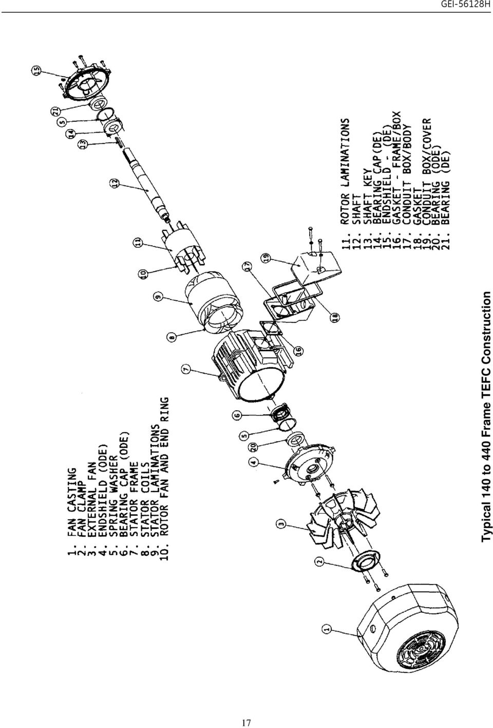
17 Typical 140 to 440 Frame TEFC Construction 17
18 Typical 500 Frame TEFC Construction - Ball Bearing Typical 500 Frame TEFC Construction - Sleeve Bearing 18

19 XI. Lubrication Guide (Excerpt from: GEK-72836E) Table 5: Motor Lubrication Guide Type of HP Lubrication Interval (Yrs.) Service Typical Examples Range Horizontal Vertical Easy Valves, door openers, portable floor sanders, motor operating infrequently (one hour per day) Standard Severe Very Severe Machine tools, air-conditioning apparatus, conveyors (one or two shafts), garage compressors, refrigeration machinery, laundry machinery, oil well pumps, water pumps, woodworking machinery Motor for fans, MG- sets, etc., that run 24 hours per day, 365 days per year; coal and mining machinery; motors subject to severe vibration; steel mill machinery Dirty, vibrating applications; where end of shaft is hot (pumps and fans); high ambient temperature months months 6 months 3 months 9 months 4 months 4 months 3 months 2 months months months 3 months months 3 months 1.5 months months 3 months 2 months 1 month --- Table 6: Number of Grease Gun Pumps Number of Pumps Number of Pumps Bearing Size on 16 Oz. Gun 24 Oz. Gun Bearing Size on 16 Oz. Gun 24 Oz. Gun Motor Nameplate (Approx. 475 ml) (Approx. 700 ml) Motor Nameplate (Approx. 475 ml) (Approx. 700 ml) ; C ; NU ; NU 320; C ; NU NOTE: A standard 10,000 PSI (69 kpa) 16 ounce (475 ml) grease gun delivers approximately 0.04 oz. (1.18 ml) of grease with each pump, and a 24 oz. (710 ml) gun delivers approximately 0.06 oz. (1.77 ml) of grease. The number of pumps listed represents approximately 20% of the total grease cavity volume in the end shield. 19

20 Document Revision History Rev # Date Author ISAAC # Description 0 09/01/99 G. Garver N/A Conversion from PageMaker 1 02/19/03 S. Long Revised to remove references to vertical oil-lubed motors. 2 06/22/10 M. Bruin Added Quantum 315 and IECEx 20

INSTALLATION AND MAINTENANCE INSTRUCTIONS FOR THREE PHASE INDUCTION MOTORS
 INSTALLATION AND MAINTENANCE INSTRUCTIONS FOR THREE PHASE INDUCTION MOTORS Frames 143T - 449TZ 5100 North IH 35 Round Rock, Texas 78681 Phone: 800-451-8798 512-255-4141 Fax: 512-244-5512 RECEIVING 1. Check
SINGLE PHASE MOTORS. INSTALLATION AND MAINTENANCE MANUAL March 21, 2006
 SINGLE PHASE MOTORS INSTALLATION AND MAINTENANCE MANUAL March 21, 2006 Irvine, California (800) 474-0520 Indianapolis, Indiana (800) 866-7973 Hamilton, Ontario (800) 809-0330 e-mail: sales@sterlingelectric.com
SEWER CHEWER Wastewater / Sludge Grinder Submersible Gearmotor
 INSTALLATION, OPERATION AND MAINTENANCE MANUAL For SEWER CHEWER Wastewater / Sludge Grinder Submersible Gearmotor Yeomans Chicago Corporation 3905 Enterprise Court P.O. Box 6620 Aurora, IL 60598-0620 Phone:
IMPORTANT SAFETY NOTICE
 IMPORTANT SAFETY NOTICE To: Our Valued Customers User safety is a major focus in the design of our products. Following the precautions outlined in this manual will minimize your risk of injury. ITT Goulds
AC Electric Motors best practice
 If you want to learn more about best practice machinery maintenance, or world class mechanical equipment maintenance and installation practices, follow the link to our Online Store and see the Training
Industrial Process Pump Safety Manual IMPORTANT SAFETY NOTICE
 Industrial Process Pump Safety Manual IMPORTANT SAFETY NOTICE To: Our Valued Customers User safety is a major focus in the design of our products. Following the precautions outlined in this manual will
IEC Three Phase AC Motors (Aluminum Frame) Installation & Operating Manual
 Installation & Operating Manual") IEC Three Phase AC Motors (Aluminum Frame) Installation & Operating Manual 7/09 MN301 Table of Contents Section 1 General Information.................................................. 1-1 Overview........................................................
IEC Three Phase AC Motors (Aluminum Frame) Installation & Operating Manual 7/09 MN301 Table of Contents Section 1 General Information.................................................. 1-1 Overview........................................................
(3) Explosion proof. Designed to prevent ignition of any explosive gases or dust and dirt which may surround the motor.
 Explosion proof. Designed to prevent ignition of any explosive gases or dust and dirt which may surround the motor.") ELECTRIC MOTORS Enclosures for Motors Types of motor enclosures generally used in farm applications: (1) Open type; drip proof or splash-proof. A general purpose motor for use in dry locations which are
ELECTRIC MOTORS Enclosures for Motors Types of motor enclosures generally used in farm applications: (1) Open type; drip proof or splash-proof. A general purpose motor for use in dry locations which are
Oil and Coolant Circulating Heating System. Model - OCSM
 Oil and Coolant Circulating Heating System Model - OCSM Installation & Operation Manual 216280-000 REV 2 Identifying Your System The HOTSTART heating system is designed to heat fluids for use in marine
Trouble Shooting. Pump
 Trouble Shooting Pump Trouble Possible Cause Remedy Oil leaking in the area of water pump crankshaft Worn crankshaft seal, bad bearing, grooved shaft, or failure of retainer o-ring. Excessive play on crankshaft
Mechanical Installation
 Page -1-1. INTRODUCTION AND PURPOSE 1.1. This specification covers the installation, testing and precommissioning of mechanical equipment. Work is to be performed in conjunction with the manufacturer s
Packaged Terminal Air Conditioner Wall Sleeve Installation
 Installation & Maintenance Data IM 1196 Group: PTAC Part Number: 910141799 Date: October 2013 Packaged Terminal Air Conditioner Installation x 42" PGAN with Top-Mounted Hydronic Heat Note: Installation
3620 W 11th Streetб Houston, TX 77008 Telephone: 713-635-6291 Email: sales@kellogg-american.com Website: www.kellogg-american.com
 Unpackaging & Handling Be sure to carefully inspect the unit before accepting the shipment. If any damage has occurred document it with the trucking company immediately. Contact your Kellogg Distributor
Operating Manual. Los Angeles Abrasion Machine HM-70A & HM-70AF
 Operating Manual Los Angeles Abrasion Machine HM-70A & HM-70AF Rev: 07/19/2012 PHONE: 800-444-1508 P.O. Box 200, Lewis Center, Ohio 43035-0200 FAX: 800-255-5314 740-548-7298 E-mail: customerservice@gilsonco.com
Parts Replacement Manual For DODGE TORQUE-ARM Speed Reducers Straight Bore & Taper Bushed
 Parts Replacement Manual For TORQUE-ARM Speed Reducers Straight Bore & Taper Bushed TXT815A - TXT825A SIZES: TXT915A - TXT926A TXT1015A - TXT1024A WARNING: Because of the possible danger to person(s) or
SECTION 15750 PACKAGED ROOFTOP AIR CONDITIONING UNITS
 SECTION 15750 PART 1 - GENERAL 1.01 DESCRIPTION A. Section includes requirements for roof mounted, self-contained units, with electric cooling, and electric or reverse refrigeration cycle (heat pump) heating
HVAC Preventative Maintenance Basics. Presented by Mike Crawley
 HVAC Preventative Maintenance Basics Presented by Mike Crawley Air Handlers/Package Units: Coils have to be clean! The main purpose of any coil is to absorb or reject heat If coils are dirty; air flow
WE-350 Series ¼ Turn Electric Actuator
 WE-350 Series ¼ Turn Electric Actuator Operation and Installation Manual Pg 1 (Rev. 020113) Table of Contents 1.0 General 1.1 Pre-Installation Inspection 1.2 Storage 1.3 Features & General Information
PANCAKE CAPACITOR GENERATOR Installation, Operation and Maintenance Manual
 PANCAKE CAPACITOR GENERATOR Installation, Operation and Maintenance Manual A Regal Brand TABLE OF CONTENTS INTRODUCTION 2 General Data 2 Initial Inspection 2 SAFETY 2 INSTALLATION 3 Location / Environment
ELECTRIC MOTOR TEFC OPERATION & MAINTENANCE. meps Approved
 SOUTH AUSTRALIA HEAD OFFICE (Accounts / Payments) 34-36 Kinkaid Avenue NORTH PLYMPTON SA 5037 Ph: (08) 8295 5566 Fax: (08) 8295 5533 VICTORIA 23 James Street CLAYTON SOUTH VIC 3169 Ph: (03) 9544 2324 Fax:
SECTION 23 81 03 - PACKAGED ROOFTOP AIR CONDITIONING UNITS NON-CUSTOM
 SECTION 23 81 03 - PACKAGED ROOFTOP AIR CONDITIONING UNITS NON-CUSTOM PART 1 - GENERAL 1.1 SUMMARY A. Section Includes: 1. Packaged rooftop air conditioning unit (5 tons and smaller). 2. Roof curb. 1.2
Large Horizontal Induction Motor
 GE Industrial Systems GEEP-361-I Instructions Large Horizontal Induction Motor Totally Enclosed Air-to-Air Cooled Pedestal Type Sleeve Bearing These Instructions do not purport to cover all details or
! WARNING. McDonnell & Miller Installation & Maintenance Instructions MM-217(I) Series 150S and 157S (Snap Switch, All Models except 157S-RB-P)
 Series 150S and 157S (Snap Switch, All Models except 157S-RB-P)") Series 150S and 157S (Snap Switch, All Models except 157S-RB-P) Low Water Cut-Off/Pump Controllers For Steam Boilers and Other Level Control Applications McDonnell & Miller Installation & Maintenance Instructions
Series 150S and 157S (Snap Switch, All Models except 157S-RB-P) Low Water Cut-Off/Pump Controllers For Steam Boilers and Other Level Control Applications McDonnell & Miller Installation & Maintenance Instructions
IMPORTANT SAFETY RULES TO FOLLOW
 WARNING FLOOR & CARPET CLEANER Any piece of equipment can be dangerous if not operated properly. YOU are responsible for the safe operation of this equipment. The operator must carefully read and follow
AC Submersible Pump Motors Installation & Operating Manual
 AC Submersible Pump Motors Installation & Operating Manual 2/12 Any trademarks used in this manual are the property of their respective owners. Table of Contents Section 1 General Information... Overview...
We will discuss common industrial applications with guides for the proper use of electric motors on these.
 INTRODUCTION: Baldor Electric Company has prepared this Specifiers Guide to help you cover all the bases when you are specifying electric motors. It will cover in a generic way most of the subjects which
Roller Chain Coupling
 Roller Chain Coupling Features 1. Simple structure A roller chain coupling consists of one duplex roller chain and two sprockets for a simplex chain. Handling is very simple as both the shafts (driving
Evaluate, Clean, and Tune Guidance
 Evaluate, Clean, and Tune Guidance The Evaluate, Clean and Tune (ECT) process serves three essential purposes in the Weatherization Assistance Program (WAP). The first is to evaluate the existing system
with MERCURY FREE 1 HP Relays ! WARNING Before using this product read and understand instructions.
 B Installation & Maintenance Instructions MM-414 Series 150E and 157E Low Water Cut-Off/Pump Controllers For Steam Boilers and Other Level Control Applications A Typical Applications: Primary or secondary
Pump Specifications 250 Series Submersible Sump / Effluent Pump 2 Solids handling
 Pump Specifications 250 Series Submersible Sump / Effluent Pump 2 Solids handling 250_P1 R10/7/2015 Copyright 2015 Liberty Pumps Inc. All rights reserved. Specifications subject to change without notice.
Select Radiators Installation Guide
 Select Radiators Installation Guide Table of Contents Informational Symbols...3 Before You Begin...4 Select Rough-In... 5 Connection Installation...6 Optional Piping Arrangements...7 Conventional Wall
300 SERIES 331, 332, 333, 344, 356 AND 367 MODELS
 Section: MOYNO 500 PUMPS Page: 1 of 8 Date: March 1, 1998 SERVICE MANUAL MOYNO 500 PUMPS 300 SERIES 331, 332, 333, 344, 356 AND 367 MODELS Mechanical Seal Models Packing Gland Models MODELS DESIGN FEATURES
300 Series PA Pump and Cooler Assemblies
 Type 300 Series PA Sizes 300 thru 370 (Page 1 of 9) 300 Series PA Pump and Cooler Assemblies Pump and Cooler Assemblies with Air/Oil Heat Exchanger When compact gear drives require assistance to dissipate
Guide for Installation and Maintenance of MacroAir (ME Series) High Volume Low Speed Fans
 High Volume Low Speed Fans") Guide for Installation and Maintenance of MacroAir (ME Series) High Volume Low Speed Fans Version 9.0 April 2014 1 Delivery: Upon receipt of fans, thoroughly inspect units for any damage sustained during
Guide for Installation and Maintenance of MacroAir (ME Series) High Volume Low Speed Fans Version 9.0 April 2014 1 Delivery: Upon receipt of fans, thoroughly inspect units for any damage sustained during
Consortiwm Awdurdodau Lleol Cymru Consortium Local Authorities Wales
 Consortiwm Awdurdodau Lleol Cymru Consortium Local Authorities Wales SPECIFICATION FOR LAUNDRY EQUIPMENT MAINTENANCE Maintenance Module 32 March 2011 issue This document has been compiled by the Engineering
Regal Beloit AC Motors
 Installation, Operation and Maintenance Instructions for Industrial AC Induction Motors 140-6800 Frames (NEMA) 90 280 Frames (IEC) Regal Beloit AC Motors LEESON ELECTRIC Contact Motor Customer Service
RAY-MAX Integrated Solar Power Strip
 RAY-MAX Integrated Solar Power Strip 600008, 600009, 600010, 600208, 600209, 600210 Owner s Manual NEXTRONEX, INC. Revision Date: 10/27/14 Contents 1. Safety Instructions... 3 2. General Equipment Warnings...
Installation. Centrifugal Roof and Wall Exhausters
 This publication contains the installation, operation and maintenance instructions for standard units of the AC- Centrifugal Roof and Wall Exhausters. ACE-D / ACE-B ACW-D / ACW-B / ACW-HP / ACW-XP ACRU-D
ATS Overhead Table Shelf System INSTRUCTION MANUAL
 ATS Overhead Table Shelf System INSTRUCTION MANUAL ATS Overhead Table Shelf System Instruction Manual Warranty Newport Corporation warrants this product to be free of defects in material and workmanship
Single-Phase AC Synchronous Generator
 ST Series Single-Phase AC Synchronous Generator Instructions for Operation and Maintenance English to English translation by R.G. Keen, May 2004. ST Series of Single-Phase AC Synchronous Generators Description
Installation Instructions for Alarm Module Kit A043F059
 Instruction Sheet 07-2013 Installation Instructions for Alarm Module Kit A043F059 1 Introduction The information contained within is based on information available at the time of going to print. In line
Float and Thermostatic Traps Series H, C and X
 Hoffman Specialty Installation & Maintenance Instructions HS-(E) and Thermostatic Traps Series H, C and X Series C & NPT Series C NPT Series X NPT Series C NPT Series H Ratings Maximum Max. Operating NPT
OPERATING AND MAINTENANCE INSTRUCTIONS PUMP TYPE 215.10
 OPERATING AND MAINTENANCE INSTRUCTIONS PUMP TYPE 215.10 To Pump model Pump number Our order Your order Order date Reference Item number Destination Plant Before storing, installation, operation or maintenance
BATHROOM HEATER. User's Manual. Page 2...A515 Page 9...A716
 BATHROOM HEATER User's Manual Page 2...A515 Page 9...A716 BATHROOM HEATER User's Manual A515 SAVE THESE INSTRUCTIONS AND READ ALL INSTRUCTIONS BEFORE USING THE HEATER. Dear customers, Thank you for selecting
Operation Instructions. KleeBlower Compressor/Vacuum pumps. Models: KB129 KB8415
 Operation Instructions KleeBlower Compressor/Vacuum pumps Models: KB129 KB8415 Brd. Klee A/S All rights reserved Edition 01/2012 Head office: Branch office: Brd. Klee A/S Klee Engineering Ltd Gadagervej
Series 30000 Hose Reels
 Operating Instructions and Parts List for Series 30000 Hose Reels - MANUAL DRIVEN - - POWER DRIVEN - SAFETY PRECAUTIONS Personal injury and/or equipment damage may result if proper safety precautions are
Volkswagen Jetta, Golf, GTI 1999, 2000 2.8 Liter VR6 2V Engine Mechanical, Engine Code(s): AFP 17 Engine-Lubrication (Page GR-17)
: AFP 17 Engine-Lubrication (Page GR-17)") 17 Engine-Lubrication (Page GR-17) Lubrication system components, removing and installing Oil filter housing, disassembling and assembling Oil pan, removing and installing Oil pressure and oil pressure
17 Engine-Lubrication (Page GR-17) Lubrication system components, removing and installing Oil filter housing, disassembling and assembling Oil pan, removing and installing Oil pressure and oil pressure
Table of Contents. Overview 1. Pump Disassembly 2. Control Disassembly / Reassembly 7. Pump Reassembly 13. Adjustment Procedures DR Control 19
 Table of Contents Overview 1 Pump Disassembly 2 Control Disassembly / Reassembly 7 Pump Reassembly 13 Adjustment Procedures DR Control 19 Adjustment Procedures DRG Control 20 Adjustment Procedures DFR
ARCO Electric Products Installation and Maintenance Manual Low Voltage Automatic Power Factor Correction Capacitor Systems 2013
 ARCO Electric Products Installation and Maintenance Manual Low Voltage Automatic Power Factor Correction Capacitor Systems 2013 READ CAREFULLY These instructions are intended to cover good practices in
CARING FOR YOUR WATER HEATER
 http://waterheatertimer.org/troubleshoot-rheem-tankless-water-heater.html Water Heater Inspections CARING FOR YOUR WATER HEATER Venting System (Direct Vent Only) The venting system should be inspected
Dehumidifier Users manual. For Models: DH45S DH65S
 Dehumidifier Users manual For Models: DH45S DH65S 950-0062-revD Jan. 9 2007 FORWARD The appearance of the units that you purchase might be slightly different from the ones described in the Manual, but
Installation, Operation and Maintenance Instructions
 Installation, Operation and Maintenance Instructions for AC Induction Motors 56-6800 Frames (NEMA) 63 280 Frames (IEC) MARATHON ELECTRIC Contact Motor Customer Service at: Phone: (75) 675-33 www.marathonelectric.com
USER INSTRUCTIONS FOR GET PORTABLE 12k BTU AIR CONDITIONER MODEL No. GPACU12HR
 USER INSTRUCTIONS FOR GET PORTABLE 12k BTU AIR CONDITIONER MODEL No. GPACU12HR CONTENTS Introduction Safety Notes Identification of parts Installation instructions Operation instructions Maintenance Troubleshooting
PBX Series Quick Fit Connector Bimetallic Steam Traps
 6262100/6 IM-P626-01 ST Issue 6 PBX Series Quick Fit Connector Bimetallic Steam Traps Installation and Maintenance Instructions 1. Safety information 2. General product information 3. Installation 4. Commissioning
Cooktop Low-Profile Ventilation Hoods
 INSTALLATION GUIDE Cooktop Low-Profile Ventilation Hoods Contents Wolf Cooktop Low-Profile Ventilation Hoods........ 3 Cooktop Low-Profile Hood Specifications.......... 4 Cooktop Low-Profile Hood Installation............
SE-100-1, SE-200-1, SE-500-1, and SE-1000-1 AIR CHAMP PRODUCTS. User Manual SE BRAKE MODELS: (i) MTY (81) 83 54 10 18 ventas@industrialmagza.
 MTY (81) 83 54 10 18 ventas@industrialmagza.") AIR CHAMP PRODUCTS User Manual SE BRAKE MODELS: SE-00-, SE-200-, SE-500-, and SE-000- (i) FORM NO. L-20084-E-040 In accordance with Nexen s established policy of constant product improvement, the specifications
AIR CHAMP PRODUCTS User Manual SE BRAKE MODELS: SE-00-, SE-200-, SE-500-, and SE-000- (i) FORM NO. L-20084-E-040 In accordance with Nexen s established policy of constant product improvement, the specifications
Explosion proof enclosures
 1 of 7 Explosion proof enclosures DE8 C 2 of 7 The Ex d enclosures are rugged and designed for harsh environment like: Oil and gas industry Chemical industry Pharmaceutical industry Agribusiness Without
Constantemp Double Wall Low pressure steam-water Heater F-340LDW,F-640LDW, F-940LDW and F-1240LDW
 Installation, Operating and Maintenance Instructions 90/4.5.5 Rev. 0 Constantemp Double Wall Low pressure steam-water Heater F-340LDW,F-640LDW, F-940LDW and F-1240LDW Table of Contents SECTION I... 2 INSTALLATION...
FJ2. 2 Ton Trolley Floor Jack Assembly & Operating Instructions
 FJ2 2 Ton Trolley Floor Jack Assembly & Operating Instructions READ ALL INSTRUCTIONS AND WARNINGS BEFORE USING THIS PRODUCT. This manual provides important information on proper operation & maintenance.
System Saver 318 Air Compressor for Mack E-Tech and ASET Engines
 Maintenance Manual 31 System Saver 318 Air Compressor for Mack E-Tech and ASET Engines Revised 08-05 NON-THROUGH DRIVE THROUGH DRIVE Service Notes About This Manual This manual provides service and repair
This instruction is valid for all ACD pump models shown on page 2
 Screw pumps ACD Maintenance and Service Instruction This instruction is valid for all ACD pump models shown on page 2 Contents Page List of components 2 Exploded view/ordering code 3 Service intervals
TECHNICAL SERVICE MANUAL
 TECHNICAL SERVICE MANUAL HEAVY-DUTY PUMPS SERIES 4195 AND 495 SIZES GG - AL SECTION TSM 144 PAGE 1 of 10 ISSUE D CONTENTS Introduction....................... 1 Safety Information.................... 2
3. SEISCO PARTS & SERVICE REMOVAL AND REPAIR GUIDE
 4 3. SEISCO PARTS & SERVICE REMOVAL AND REPAIR GUIDE A. Changing the Control Board B. Replacing a Heating Element C. Thermistor Replacement D. High Limit Switch Replacement E. Level Detector Replacement
FAIRBANKS NIJHUIS FIRE PUMPS. www.fairbanksnijhuis.com
 FAIRBANKS NIJHUIS FIRE PUMPS www.fairbanksnijhuis.com FAIRBANKS NIJHUIS Long established as a leading fire pump manufacturer, Fairbanks Nijhuis offers a broad range of horizontal and vertical split case,
DODGE USAF 200/300 Direct Mount Pillow Block Bearings
 DODGE USAF 200/300 Direct Mount Pillow Block Bearings These instructions must be read thoroughly before installation or operation. WARNING: To ensure that drive is not unexpectedly started, turn off and
Ceiling Mount Air Handler Manual
 www.surna.com 303.993.5271 Ceiling Mount Air Handler Manual Models: CMAH12, CMAH18, CMAH24, CMAH30, CMAH36, CMAH48, CMAH60 Revised: September 2014 Table of Contents Warranty Information 4 Limited Warranty
Model 362A AURORA. 340A/360A Series SINGLE STAGE END SUCTION PUMPS. www.aurorapump.com
 Model 62A MODEL 41A MODEL 44A AURORA 40A/60A Series SINGLE STAGE END PUMPS www.aurorapump.com SINGLE STAGE END PUMPS AURORA 40A/60A Series Single Stage End Suction Pumps Capacities to 4500 G.P.M. (1022
Failure to comply with the following cautions and warnings could cause equipment damage and personal injury.
 1.0 IMPORTANT RECEIVING INSTRUCTIONS Visually inspect all components for shipping damage. Shipping Damage is not covered by warranty. If shipping damage is found, notify carrier at once. The carrier is
UB1 AIR CONDITIONING UNIT INSTALLATION INSTRUCTIONS
 UB1 AIR CONDITIONING UNIT INSTALLATION INSTRUCTIONS INSTALLATION INSTRUCTIONS: Carefully read these instructions before installing your new air-conditioner. AUSTRALIAN AUTOMOTIVE AIR AL00500054E 1 Table
SWIMMING POOL HEAT PUMP
 SWIMMING POOL HEAT PUMP Installation & User Manual Model HP40B HP50B HP65B Hayward Pool Products Canada, Inc. T: 1-888-238-7665 www.haywardpool.ca CONTENT I. Application 4 II. Features 4 III. Technical
Owner s Manual. Models: 2S5P & 3S5P OPERATION AND MAINTENANCE OF SELF-PRIMING CENTRIFUGAL TRASH PUMPS PEDESTAL DRIVE
 Owner s Manual Models: 2S5P & 3S5P OPERATION AND MAINTENANCE OF SELF-PRIMING CENTRIFUGAL TRASH PUMPS PEDESTAL DRIVE WARNING!! Installation & Operating Instructions Self-Priming Centrifugal Pump DO NOT
01-3 6820-11 6820-11 AIR CONDITIONER GENERAL 1. SPECIFICATIONS AIR CONDITIONER REXTON 2010.01
 682011 013 GENERAL 1. SPECIFICATIONS 682011 014 682011 2. REPAIR INSTRUCTIONS 1) Precautions for Working with R134a R12 refrigerant and R134a refrigerant are not compatible. These refrigerants must never
3 Phase AC Induction Motors
 3 Phase AC Induction Motors INSTALLATION AND OPERATION MANUAL August 21, 2015 Indianapolis, Indiana (00) 66-93 e-mail: sales@sterlingelectric.com www.sterlingelectric.com 93 Allison Avenue, Indianapolis,
SL280UHV SERIES GAS FURNACE WARNING
 2010 Lennox Industries Inc. Dallas, Texas, USA 506677 01 11/2010 Supersedes 506409 01 SL280UHV SERIES GAS FURNACE Litho U.S.A. FIRE OR EXPLOSION HAZARD. Failure to follow safety warnings exactly could
UHIR Series. Horizontal or Vertical Mounting Industrial / Commercial Electric Unit Heater. Owner s Manual
 UHIR Series Horizontal or Vertical Mounting Industrial / Commercial Electric Unit Heater Owner s Manual This manual covers installation, maintenance and repair parts. Read carefully before attempting to
ELECTRICAL SAFETY. The standard unit for measuring electrical current.
 ELECTRICAL SAFETY Introduction The following sections provide general safety guidelines and procedures for electrical safety. This chapter covers the following topics: TOPIC PAGE General Electrical Safety
Pump Skid Fabrication for Magnetic Coupling. Rick Soltis Chief Mechanic City of Bedford
 Pump Skid Fabrication for Magnetic Coupling Rick Soltis Chief Mechanic City of Bedford Contents Magnetic Couplings What They Are, How They Work, Where They re Used Fabrication and Manufacturing of Pump
12V Portable Diaphragm Compressor Operating and Maintenance Instructions
 12V Portable Diaphragm Compressor Operating and Maintenance Instructions (Part No. DC2) Part No. Serial Number Date Purchased Table of Contents Page Safety Messages...2 Guidelines for Product Use...2 Operation
Model 1210C Battery Powered Pump Shown. Description
 12 Volt DC Rotary Vane Pump Series 1200C Model 1210C Battery Powered Pump Shown Description of Included Models Model Number FR1205C FR1210C FR1211C FR2410C FR2411C Description Basic 12 volt DC pump with
Fire Pump Applications
 Fire Pump Applications Installation & Maintenance Manual Universal Joint Driveshafts www.cumminsfirepower.com Table of Contents Section 1 General 1.1 Introduction 1.2 Safety Precautions 1.3 Warranty Statement
SALVAGING FLOOD DAMAGED ELECTRICAL EQUIPMENT
 SALVAGING FLOOD DAMAGED ELECTRICAL EQUIPMENT Overview In all drying out of electrical windings, the regulation of temperature should be controlled carefully. Maximum drying temperatures on windings should
DiscPlus DX195 and DX225 Air Disc Brakes
 Revised 11-04 Technical Bulletin Revised 1 Technical 11-04 Bulletin DiscPlus DX195 and DX225 Air Disc Brakes Inspection, Installation and Diagnostics Air Disc Brake Inspection Intervals and Procedures
Single Phase Soft Starter
 Single Phase Soft Starter Installation & Operating Manual 6/02 Table of Contents Section 1 General Information................................................... 1 1 General Description................................................
SunMaxx Solar Filling Station Operating Instructions
 SunMaxx Solar Filling Operating Instructions Content 1. Declaration of conformity... 2 2. Introduction... 2 3. Transportation and unpacking... 4 4. Mounting and commissioning... 5 5. End of operation...
PALLET JACK - 2.5 TON
 PALLET JACK - 2.5 TON 39939 SET UP AND OPERATING INSTRUCTIONS Visit our website at: http://www.harborfreight.com Read this material before using this product. Failure to do so can result in serious injury.
Chapter 7 Hydraulic System Troubleshooting
 Chapter 7 Hydraulic System Troubleshooting General The following troubleshooting information is provided as a general guide to identify, locate and correct problems that may be experienced with the hydraulic
Table V. Troubleshooting Checklist for Refrigeration Systems. Air or non-condensable gas in system. Inlet water warm.
 Table V Troubleshooting Checklist for Refrigeration Systems TROUBLE POSSIBLE CAUSE CORRECTIVE MEASURE High condensing pressure. Low condensing pressure. Air or non-condensable gas in system. Inlet water
SERIES ASM NEOPRENE/EPMD FLANGED SINGLE SPHERE CONNECTOR CONNECTORS. Pressures to 225 PSIG (15.51 barg) Temperatures to 230ºF (110ºC)
 Temperatures to 230ºF (110ºC)") APPLICATIONS Process Industry Weak Acids Alkalies Compressed Air Pulp & Paper MODELS ASM - Flanged Connection OPTIONS Control Rods Oil & Gas Water & Waste Pump suction & discharge Sea water Chemical lines
APPLICATIONS Process Industry Weak Acids Alkalies Compressed Air Pulp & Paper MODELS ASM - Flanged Connection OPTIONS Control Rods Oil & Gas Water & Waste Pump suction & discharge Sea water Chemical lines
Portable Air Conditioner
 Portable Air Conditioner Owner's Manual Model:3 in 1 12,000 Btu/h Series 3 Please read this owner s manual carefully before operation and retain it for future reference. CONTENTS 1. SUMMARY...1 2. PORTABLE
Horizontal Jet Pumps 1/3-1-1/2 HP
 Horizontal Jet s 1/3-1-1/2 FW01 0909 Supersedes 0409 The CPJ, CPH and EK models feature the famous Flint and Walling Service Plus motor, available in either NEMA J or Uni-frame flange construction. The
A.Y. McDonald Mfg. Co. Troubleshooting Submersible and Jet Pumps
 A.Y. McDonald Mfg. Co. Troubleshooting Submersible and Jet Pumps Troubleshooting Submersible Pumps Fuse overload or circuit breaker trips when motor is started 1. Incorrect line voltage. Check the line
AKRAPOVIC SLIP-ON EXHAUST SYSTEM for the HONDA CB1000R
 Installation instructions: *502131* AKRAPOVIC SLIP-ON EXHAUST SYSTEM for the HONDA CB1000R Congratulations on purchasing an Akrapovic exhaust system. Please read these installation instructions carefully.
COMMERCIAL COOKING HOODS, VENTILATION & FIRE SUPPRESSION SYSTEM GUIDELINES AND PROCEDURES
 COMMERCIAL COOKING HOODS, VENTILATION & FIRE SUPPRESSION SYSTEM GUIDELINES AND PROCEDURES These guidelines are to be used for ALL commercial cooking hoods, ventilation systems and related fire suppression
PC1130 Electric Air Compressor
 Senco Products Inc. 8485 Broadwell Road Cincinnati, Ohio 45244 PC1130 Electric Air Compressor Operating Instructions 2006 by Senco Products, Inc. Warnings for the safe use of this tool are included in
INSTALLATION, OPERATION & MAINTENANCE INSTRUCTIONS ELECTRIC HEATING UNITS MODEL: ETA / EKI
 INSTALLATION, OPERATION & MAINTENANCE INSTRUCTIONS ELECTRIC HEATING UNITS MODEL: ETA / EKI Page 2 / 16 CONTENTS 1 GENERAL... 3 2 SAFETY... 3 2.1 Safety instructions... 3 2.2 Correct use... 3 3 DESCRIPTION
INSPECTION, MAINTENANCE AND RECHARGE SERVICE MANUAL P/N 16303
 WATER MIST HAND PORTABLE FIRE EXTINGUISHERS Model B270 ¾ Gallon Model B272 2 ½ Gallon INSPECTION, MAINTENANCE AND RECHARGE SERVICE MANUAL P/N 6303 All fire extinguishers should be installed, inspected
Q&A Session for Advanced Ball Screws 102: Troubleshooting for Design Engineers
 Q&A Session for Advanced Ball Screws 102: Troubleshooting for Design Engineers Topic: Noise Q: Is there a way to predict/calculate noise on a ball screw? A: No, there is no way to calculate the noise of
Service manual. Website: www.andico.com.au CAUTION - BEFORE SERVICING THE UNIT, READ THE SAFETY - PRECAUTIONS IN THIS MANUAL.
 Website: www.andico.com.au Service manual CAUTION - BEFORE SERVICING THE UNIT, READ THE SAFETY - PRECAUTIONS IN THIS MANUAL. - ONLY FOR AUTHORISED SERVICE PERSONNEL. MODELS: MPK1-09CR-QB8 MPK1-12ER-QB6
OASIS-PLUS 120V READ ALL INSTRUCTIONS BEFORE OPERATING READ ALL INSTRUCTIONS BEFORE OPERATING OZONE IS A POWERFUL OXIDIZER AND MUST BE USED WITH CARE
 OASIS-PLUS 120V INFORMATION & OPERATING INSTRUCTIONS READ ALL INSTRUCTIONS BEFORE OPERATING READ ALL INSTRUCTIONS BEFORE OPERATING OZONE IS A POWERFUL OXIDIZER AND MUST BE USED WITH CARE 56041852 WARNING:
CEILING CASSETTE FAN COIL UNIT
 CEILING CASSETTE FAN COIL UNIT Operation and Installation Manual MHCFC4W-04, 08, 12, 16 Four way ceiling cassette fan coil unit Please read this manual before using the fan coil unit. Installation and