An Evaluation of. Swimming Pool Alarms
|
|
|
- Stuart Joseph
- 8 years ago
- Views:
Transcription
1 An Evaluation of Swimming Pool Alarms May 2000 Troy W. Whitfield Division of Mechanical Engineering Directorate for Engineering Sciences

2 EXECUTIVE SUMMARY On average each year 350 children under the age of five years drown in swimming pools, with most deaths occurring in residential settings. Also each year, on average, another 2,600 children under five years of age are treated in hospital emergency rooms for near-drowning incidents in swimming pools. About 79 percent of these incidents occur at a home location. These numbers have remained relatively unchanged over the past several years. During 1999 and early 2000, the U.S. Consumer Product Safety Commission (CPSC) staff conducted a review of commercially available swimming pool alarm systems designed to detect water disturbance or displacement. There are no voluntary standards that define applicable performance requirements for disturbance or displacement type products. The CPSC staff evaluated four water disturbance alarms and a wristband. Two of the disturbance systems used surface wave detection circuitry, while the other two detected subsurface disturbances. The fifth device was a wristband (to be worn by a child) intended to alarm when exposed to water. All of the products incorporated remote alarm receivers, some at an additional cost. Test results showed that the subsurface pool alarms generally performed better. They were more consistent in alarming and less likely to false alarm than the surface alarms. When a test object, intended to simulate the weight of a small child, was pushed into the pool, the subsurface sensors detected it most reliably. The subsurface alarms can also be used in conjunction with solar covers, whereas the surface alarms cannot. One surface alarm performed almost as well as the subsurface alarms. The wristband alarmed when submerged in pool water or exposed to another water source, such as tap water. ii
 staff conducted a review of commercially available swimming pool alarm systems designed to detect water disturbance or displacement.")
3 TABLE OF CONTENTS EXECUTIVE SUMMARY ii TABLE OF CONTENTS..iii INTRODUCTION..1 MARKET INFORMATION..1 ALARM SYSTEM TECHNOLOGIES..2 TEST FACILITIES TEST METHODOLOGY TEST RESULTS DETECTION.11 TEST RESULTS FALSE ALARM 14 CONCLUSION..14 Appendix A - Test results from Pool 1 Appendix B - Test results from Pool 2 Appendix C - Test results from Pool 3 Appendix D - Test results from Pool 4 Appendix E - Test results from Pool 5 Appendix F - Test results from Pool 6 iii

4 INTRODUCTION Each year, on average, 350 children under five years of age drown in swimming pools, with most deaths occurring in residential settings. Also each year, on average, 2,600 children under five years of age are treated in hospital emergency rooms for near-drowning incidents in swimming pools. About 42 percent of the incidents require hospitalization of the child. About 79 percent of the near-drowning incidents occur in a residential setting. These numbers have remained relatively unchanged for the past several years (see graph below). Drowning 1 and Near Drowning 2 Incidents for Children Under Age Five Number of Incidents Drowning 1995 Year Near Drowning 1 Rounded to the nearest ten CPSC Death Certificate and Injury or Potential Injury Incident Files, CPSC National Electronic Injury Surveillance System (NEISS), During 1999 and early 2000, the U.S. Consumer Product Safety Commission (CPSC) staff conducted a review of commercially available swimming pool alarm systems designed to address pool-related injuries and drowning. A similar assessment was conducted in Product designs have not changed significantly from that time. The staff s review focused on water intrusion alarm systems designed to sense disturbance or displacement of the pool water. In addition, the staff assessed a wristband that alarms remotely when exposed to water. MARKET INFORMATION Water intrusion devices including a remote alarm are priced from $149 to $200 for surface wave sensor alarms and between $190 and $250 for subsurface disturbance sensor alarms. The wristband alarm system, an intrusion detector recently introduced, costs $179 for one wristband and the remote alarm. It is estimated that about 24,000 pool alarms are sold annually and that sales have doubled since Memo from Ronald L. Medford to the Commission, Contract Report on Testing of Swimming Pool Alarms, April 21,
.")
5 According to recent estimates by the National Spa and Pool Institute (NSPI), there are about 7 million residential pools in the continental United States. Approximately 3.8 million pools are inground (constructed of gunite, vinyl, or fiberglass), and 3.2 million are above ground. Pool sales are from 120,000 to170,000 annually for inground pools and 300,000 to almost 500,000 for above ground pools, with the majority of inground pools being of gunite construction. ALARM SYSTEM TECHNOLOGIES There are no voluntary standards addressing performance or design requirements for pool water disturbance or displacement type alarm systems. Staff evaluated four different alarm systems and a wristband with remote alarm to determine their effectiveness in detecting water intrusions. Two of the displacement/disturbance devices detected surface waves while the other two detected subsurface disturbances. A fifth device was a wristband (to be worn by a child) which detected exposure to water. All of the products incorporated remote alarm receivers. All of the alarm systems required 9-Volt batteries for operation. The remote alarm receivers required a 120 Volt outlet (step-down transformers were supplied with the power cords). One product offered the option of operating on a 9-Volt battery as well as on a 120-Volt source, which would provide continued operation during a power outage. Surface Wave Sensors Two surface wave sensors were evaluated. This type of sensor floats on the water surface. The sensor incorporates an electrical circuit that includes two contacts. One contact rests in the water; the second contact (above-surface contact) is adjusted so that it is resting above the water. When the above-surface contact is touched by water (from a surface wave), the electrical circuit is completed and an alarm sounds. The sensitivity of the device can be adjusted by positioning the above-surface contact closer or further away from the water surface. Sensitivity increases as the contact is positioned closer to the water surface (see Figures 1 and 2). Subsurface Disturbance Sensors Two subsurface disturbance sensors were evaluated. These sensors mount on the side of a pool, with portions of the devices being located 1/2 to 12 inches below the water surface. Each device relies on a wave-induced pressure change to activate alarm circuitry. One type of sensor (see Figure 3) uses a pressure-sensitive switch located at the top of a sensing throat. Water movement creates pressure changes within the sensing throat, which activates a switch to initiate an alarm. The other device relies on movement of a magnetic float below a magnetic sensor to create a signal that activates the alarm (see Figure 4). Both sensors use electrical adjustments to control circuit response to stimuli. One of the subsurface sensors also uses a mechanical adjustment for the depth of the sensor to increase or decrease sensitivity. Sensitivity increases when the sensor is located closer to the water surface; the device is less responsive when it is placed farther below the surface. 2

6 Figure 1. Surface Wave Sensor (Sensor A) 3

7 Figure 2 Surface Wave Sensor (Sensor B) 4

8 Figure 3. Subsurface Disturbance Sensor (Sensor C) 5

9 Figure 4. Subsurface Disturbance Sensor (Sensor D) 6

10 Wristband A wristband with a remote alarm was also evaluated (see Figure 5). The wristband must be placed on a child s arm by a parent or caregiver; a locking key prevents the child from removing the band. When the sensor on the band becomes wet, the remote alarm is activated, warning the parent that the wristband has been exposed to water. There are no sensitivity adjustments for the wristband. The wristband is battery operated, and the unit is sealed. Once the battery is discharged, the wristband sensor must be replaced. The user must be cognizant of the receiver turtle color and be sure the replacement wristband matches that color to insure proper alarm operation. TEST FACILITIES Alarm tests were conducted at six different pool sites. The pools were both indoors and outdoors and differed in size, shape, and depth. The reason for different test sites was to determine whether the shape and depth of the pool had any influence on the effectiveness of the alarms. The pools varied in width from 14 feet to 30 feet and length from 35 feet to 50 feet. All but one pool were of the spoon design, starting at a depth of 3-4 feet and going to a depth of 6 to 10 feet. The one exception was an indoor/outdoor pool of the hopper design where both ends were 3½ feet deep and the depth at the center of the pool was 6 feet. TEST METHODOLOGY The manufacturers instruction manuals were reviewed prior to testing. Alarm systems were assembled and placed around the test pools (diagrams provided in appendices) according to the instructions. The surface wave sensors (labeled A * and B in the figures of appendices A-F) were tied to tethers (between two and six feet long) and centrally located along the perimeter of the pools. An effort was made to maintain a distance of at least six inches between the sensor and the pool wall, according to the manufacturers instructions. The subsurface disturbance sensors (labeled C * and D * ) were placed at the deep end of the pools. The sensitivity of each unit was adjusted during preliminary testing to obtain the best performance results. The remote alarm function for each sensor was also tested. The systems were tested under two conditions: Detection To determine whether the surface and subsurface wave sensors would alarm when a test object entered the pool, and To determine whether the wristband would alarm when exposed to pool water. * A=PoolSOS/Allweather Inc., C=Poolguard/PBM Industries, D=Sentinel LINK/Lambo Products Inc. 7

11 Figure 5. The Wristband and Receiver 8

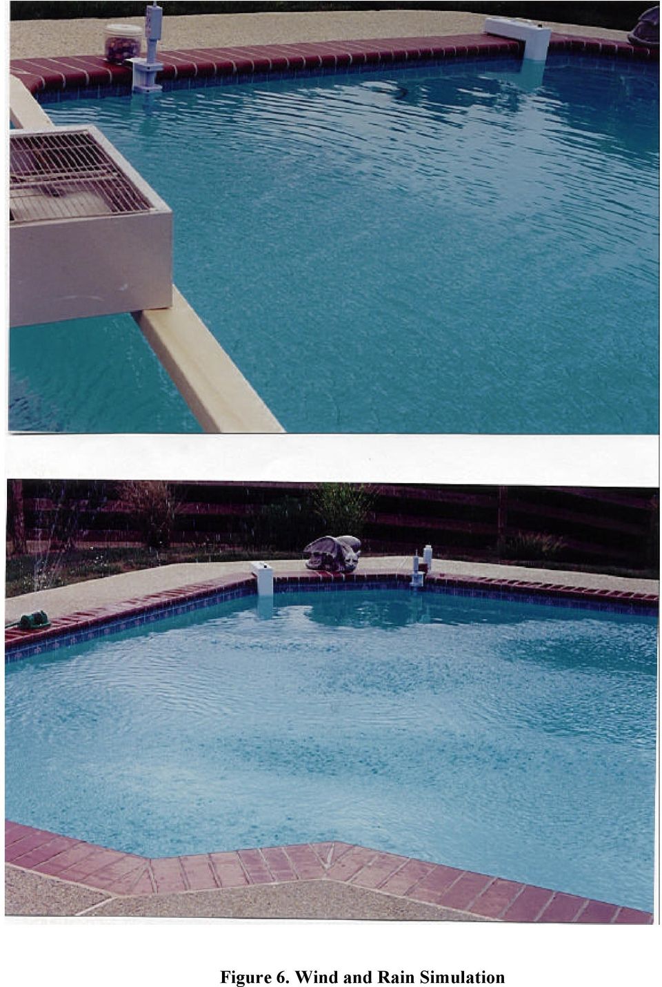
12 False Alarm To determine the susceptibility of the surface and subsurface wave sensors to alarm when water displacement was not created by the test object, and To determine whether the wristband would alarm under non-threatening conditions, such as washing hands. Detection (Surface and Subsurface Disturbance Sensors) During the first round of testing, two sets of detection tests were conducted using three, onegallon containers filled with water and tied together. One manufacturer recommended this procedure for testing the alarm sensitivity. There were ten trials conducted for each set of tests. Each trial was concluded after two minutes. The containers were positively buoyant; they would initially sink toward the bottom of the pool then rise to the surface. To conduct detection tests, the test object was placed at the pool edge and pushed into the water. To simulate worst-case conditions, the test object was pushed into the shallow end of the pool at a point farthest from the subsurface disturbance sensors. The surface wave sensors were located near the midpoint of the pool, according to manufacturers instructions. A second set of tests was performed with the test object introduced near the midpoint of the pool. The measured distance between the water entry point (marked with an X and Y, respectively) and each of the sensors (labeled A through D ) is shown in figures provided in the appendices. Subsequent rounds of testing consisted of two and three, one-gallon containers filled with water and tied together. These were used to simulate the minimum weights of a month old child (approximately 18.3 pounds) up to a month old child (approximately 25 pounds) in an effort to determine an operational sensitivity for the sensors. The lowest weight for the youngest child was chosen after a review of the CPSC database found that 1 and 2 year old children are at greatest risk of pool drowning in a home swimming pool. Two sets of detection tests were conducted with ten trials comprising each set. As with previous trials, each was concluded after two minutes. In the first set, either the two-gallon or the threegallon test object was introduced into the pool at the shallow end, generally opposite the subsurface disturbance sensor location. The distance between the surface wave sensors and the water entry point was roughly one-half to three-quarters the length of the pool. The measured distances between the water entry point and each of the sensors is shown in the figures provided in the appendices. For the second set of detection tests, the other test object was introduced from the same general location. False Alarm To determine the propensity of the surface and subsurface sensors to false (nuisance) alarm, environmental conditions likely to cause water disturbance wind and rain were simulated (see Figure 6). In addition to any wind present naturally, wind was simulated using a large household fan. The fan was supported above the water surface, and the fan speed was adjusted to its highest setting. A garden hose and sprinkler were used to simulate rainfall. Additionally, objects such as a beach ball, a basketball, and a soccer ball were introduced to determine whether an alarm distinguished between desired activation and incidental disturbances. The sensors were also left unattended for a period of time (once on a clear day and once during a rainstorm) to determine whether they would false alarm. 9

13 Figure 6. Wind and Rain Simulation
14 First Round Testing Pool 1 (Appendix A) TEST RESULTS DETECTION This test facility was a rectangular shaped pool measuring 22 x 42 with various alcoves molded into the gunite. The pool depth ranged from 3 1/2 4 feet on the shallow end up to 8 feet at the opposite end. A schematic of the pool, along with the locations of the various alarms can be found in Appendix A. As this was the first pool tested, and there are currently no performance requirements, the manufacturer-recommended three-gallon object was used for testing. From Location X (Shallow End) The first surface wave sensor, labeled A (Sensor A), alarmed in 6 out of 10 trials, with response times ranging from 16.1 seconds to 23.9 seconds. The second surface wave sensor, Sensor B, failed to alarm after two minutes in all trials. (Sensor B was set to its most sensitive detection position.) Both subsurface wave sensors alarmed 100 percent of the time. Response times for Sensor C ranged from 10.4 seconds to 76.3 seconds. Response times for Sensor D ranged from 13.3 seconds to seconds. Detection results and individual trial response times are shown in Tables A1 and A2 of Appendix A. From Location Y (Mid-point) Sensor A alarmed in 6 out of 10 trials, with response times ranging from 4.0 seconds to 25.1 seconds. Sensor B alarmed in 1 of 10 trials, with a response time of 5.7 seconds. Sensor C alarmed in all 10 trials, with response times ranging from 7.7 seconds to 10.4 seconds. Sensor D alarmed in 7 out of 10 trials. Response times ranged from 7.8 seconds to 13.4 seconds. Detection results and individual trial response times are shown in Tables A3 and A4 of Appendix A. Wristband The wristband alarmed immediately upon submersion into the pool water. Once the wristband was completely dried, it was tested again. It alarmed immediately upon submersion. Subsequent Testing Pools 2-6 (Appendices B-F) Pool 2 (Appendix B) This test facility was a rectangular pool measuring 18 x 36 with a steel and concrete shell covered with a vinyl liner. The pool was unique in that the depth ranged from 3 1/2 feet on either end up to 6 feet in the middle, a hopper design rather than the typical spoon design, shallow on one end and gradually deeper towards the opposite end. A schematic of the pool, along with the locations of the various alarms can be found in Appendix B. From Location X (Right-side of Entrance Steps) Surface wave sensor A alarmed in 5 out of 5 trials using the three-gallon test object and 5 out of 5 trials using the two-gallon test object. The response times ranged from 19.1 to 22.4 seconds 11
 The first surface wave sensor, labeled A (Sensor A), alarmed in 6 out of 10 trials, with response times ranging from 16.1 seconds to 23.9 seconds.")
15 for the three-gallon object and from 21.3 to 24.7 seconds for the two-gallon object. The second surface wave sensor, Sensor B, responded in 5 out of 5 trials for the three-gallon test object and 4 out of 5 trials for the two-gallon test object. The response times were from 7.59 to 9.71 seconds and 9.86 to seconds respectively. Both subsurface disturbance sensors alarmed 100 percent of the time. Response times for Sensor C ranged from 15.1 to 15.7 seconds with the three gallon test object and 15.0 to 19.6 seconds when the two-gallon test object was used. Response times for Sensor D ranged from 15.7 to 20.5 seconds and 20.8 to 23.5 seconds respectively. From Location Y (Left-side of Entrance Steps) Using the three-gallon object, Sensor A alarmed in 5 out of 5 trials, with response times ranging from 17.8 to 40.7 seconds. Sensor B alarmed in 3 of 5 trials, with a response time of 12.6 to 13.3 seconds. With the two-gallon object, Sensor A alarmed in 5 out of 5 trials, as did Sensor B. The response times ranged from 11.3 to 20.7 seconds for Sensor A and 11.3 to 14.4 seconds for Sensor B. Subsurface sensors C and D alarmed in all 5 trials using each object. The response times ranged from 7.4 to 12.1 seconds and 16.9 to 17.6 seconds with the three-gallon object. For the twogallon object, the times ranged from 13.0 to 20.0 seconds and 16.6 to 27.6 seconds respectively. A summary of the detection results and individual trial response times is shown in Appendix B. Pool 3 (Appendix C) This test facility was a rectangular pool measuring approximately 14 x 40 and appeared to be a typical gunite shell construction. The pool ranged from 4 feet at the entrance steps to 6 feet at the opposite end. There was a small, built-in hot tub at the shallow end adjacent to the steps. A schematic of the pool, along with the locations of the various alarms and the test results can be found in Appendix C. Due to the size and shape of the pool, and the results of the first test trials, presumed to be the worst-case scenario, there was only one drop point used for the test objects. From Location X (Shallow End) Surface wave sensors A and B alarmed in all 10 trials using both the three-gallon and the twogallon test objects. For Sensor A, the response times ranged from 7.1 to 29.8 seconds for the three-gallon object and from 7.4 to 27.0 seconds for the two-gallon object. Sensor B response times were from 9.7 to 15.1 seconds and 8.8 to 12.8 seconds, respectively. Both subsurface sensors alarmed in all 10 trials as well. Response times for Sensor C ranged from 5.8 to 15.7 seconds with the three-gallon test object and 8.8 to 22.1 seconds when the twogallon test object was used. Response times for Sensor D ranged from 15.9 to 19.0 seconds and 16.6 to 20.6 seconds, respectively. Pool 4 (Appendix D) This test facility was a rectangular pool measuring 30 x 50 and appeared to be a typical gunite shell construction. The pool ranged in depth from 4 feet at the entrance steps to 10 feet at the opposite end. A schematic of the pool, along with the locations of the various alarms and the test results can be found in Appendix D. Due to the pool size, two surface Sensor B alarms were 12

16 used. As a result of the first test trials, presumed to be a worst-case scenario, and the use of two Sensor B units (a second Sensor A was not available), there was only one drop point used for the test objects. From Location X (Shallow End) Surface wave Sensor A alarmed in all 10 trials using the three-gallon test object and in 9 out of 10 trials using the two-gallon test object. For Sensor A, the response times ranged from 25.0 to 33.4 seconds for the three-gallon object and from 14.2 to 54.6 seconds for the two-gallon object. For the two Sensor B units, there was a single response during the 10 trials using the three-gallon object. The response time was from the unit located farthest from the test object entrance point and occurred over one minute after the test object was introduced into the pool. There were two responses from each unit when using the two-gallon test object. The response times were 7.2 and 54.1 seconds from the farthest unit and 33.2 and 53.2 seconds from the nearer unit. Both subsurface sensors alarmed in all 10 trials involving the three-gallon object. Response times varied from 10.1 to 24.5 seconds for Sensor C and from 24.8 to over two minutes for Sensor D. For the two-gallon object, Sensor C alarmed in 8 out of 10 trials with response times ranging from 17.3 to 43.0 seconds while Sensor D responded in 7 out of 10 trials with response times between 31.0 and 49.3 seconds. Pool 5 (Appendix E) This test facility was a rectangular pool measuring 17.5 x 26 with additional 6 foot semi-circles on either end of the rectangle. The pool appeared to be a typical gunite shell and ranged in depth from 3 feet at the stairs to 8 feet at the opposite end. A schematic of the pool, along with the locations of the various alarms and the test results can be found in Appendix E. Due to the pool size and alarm locations, there was only one drop point used for the test objects. From Location X (Shallow End) Surface wave Sensor A alarmed in all 10 trials using the three-gallon test object and in 9 out of 10 trials using the two-gallon test object. The response times ranged from 14.1 to 21.4 seconds for the three-gallon object and from 15.1 to 20.2 seconds for the two-gallon object. The Sensor B unit responded once during the 10 trials using the three-gallon test object. The response time was 23.0 seconds. There were four responses when using the two-gallon test object. The response times ranged from were 17.1 to 23.6 seconds. Both subsurface wave sensors alarmed in all 10 trials involving both the three-gallon and the two-gallon test objects. Response times with the three-gallon test object varied from 6.3 to 10.6 seconds for Sensor C and from 9.4 to 18.1 seconds for Sensor D. For the two-gallon object, Sensor C response times were from 6.9 to 13.6 seconds while Sensor D response times were between 7.1 and 31.6 seconds. Pool 6 (Appendix F) This test facility was a kidney shaped pool measuring approximately 35.5 in length with the widest area being about 16.5 in width and 3 feet depth. The deeper end of the pool was about 13.5 in width and 8 feet in depth. This pool also appeared to be a typical gunite shell. A schematic of the pool, along with the locations of the various alarms and the test results can be 13

17 found in Appendix F. Due to the pool size, shape, and location of the alarms, there was only one drop point used for the test objects. From Location X (Shallow End) Surface wave Sensor A alarmed in all 10 trials using the three-gallon test object and in 8 out of 10 trials using the two-gallon test object. The response times ranged from 10.9 to 21.2 seconds for the three-gallon object and from 12.8 to 25.1 seconds for the two-gallon object. Surface wave Sensor B responded in 7 of the 10 three-gallon object trials and 5 out of 10 two-gallon trials. The response times were from 8.1 to 16.3 seconds and 9.7 to 11.1 seconds, respectively. Both subsurface wave sensors alarmed in all trials involving both the three-gallon and the twogallon test objects. However, there was one test involving the three-gallon object where Sensor C responded just as the test object was introduced into the pool. It was determined to be a false alarm and that trial was not counted for that sensor. The response times with the three-gallon test object were from 9.7 to 19.7 seconds for Sensor C and from 11.2 to 25.8 seconds for Sensor D. For the two-gallon object, Sensor C response times were from 8.8 to 22.2 seconds while Sensor D response times were between 16.6 and 20.6 seconds. TEST RESULTS FALSE ALARM During the first round of testing, surface wave Sensor A alarmed in conditions of simulated wind, simulated rain, and during a rainstorm. Surface wave Sensor B did not alarm during either of the environmental simulations nor during actual weather events. Neither surface wave sensor alarmed when objects were tossed into the pool unless the objected landed within approximately five feet of the sensor. Subsurface wave Sensor C did not false alarm in any of the environmental simulations or during actual weather related disturbances. Subsurface wave Sensor D did not alarm in simulated wind or rain conditions; it did alarm during the rainstorm. Neither subsurface wave sensor alarmed when objects were tossed into the pool. A summary of False Alarm Test Results is shown in the various appendices where false alarm tendencies were investigated. The wristband alarmed immediately when subjected to a stream of running tap water. CONCLUSION Test results showed that the subsurface pool alarms generally performed better. They were more consistent in alarming and less likely to false alarm than the surface alarms. When a test object, intended to simulate the weight of a small child, was pushed into the pool, the subsurface sensors detected it most reliably. The subsurface alarms can also be used in conjunction with solar covers, whereas the surface alarms cannot. One surface alarm performed almost as well as the subsurface alarms. The wristband alarmed when submerged in pool water or exposed to another water source, such as tap water. A pool alarm can be a good additional safeguard in that it provides an additional layer of protection against child drownings in swimming pools. Since pool alarms rely on someone remembering to activate them each and every time the pool is in use, they should not be relied upon as a substitute for supervision or for a barrier completely surrounding the pool. A remote 14

18 alarm feature that will sound inside the house is important to have with a pool alarm. Some alarms include this; with other alarms it has to be purchased separately. The wristband can also provide an additional layer of protection. However, it relies on someone putting it on the child and, since children often reach the pool unexpectedly from the house, it would be important for a child to wear the wristband all the time. This may present some difficulties since it alarms when exposed to any water, e.g., when washing hands. 15

19 Appendix A

20 A C X D 41 1 B 20 6 Water Entry Location Surface Wave Sensors Subsurface Wave Sensors Figure A1. Sensor Locations and Water Entry Point

21 A C D B Y Water Entry Location Surface Wave Sensors Subsurface Wave Sensors Figure A2. Sensor Locations and Water Entry Point
22 TABLE A1. DETECTION RESULTS FROM WATER ENTRY POINT X Sensor Distance to Water Entry Point Percent Detection Sensitivity Setting Response Time to Alarm (sec) A 22 ft 6 in 60 High 16.1 to 23.9 B 20 ft 6 in 0 Highest N/A SUB C 41 ft 1 in 100 Mid-Range 10.4 to 76.3 D 41 ft 1 in 100 Lowest 13.3 to TABLE A2. INDIVIDUAL TRIAL RESULTS FROM WATER ENTRY POINT X Trial Sensor P/F T (sec) P/F T (sec) P/F T (sec) P/F T (sec) P/F T (sec) P/F T (sec) P/F T (sec) P/F T (sec) P/F T (sec) P/F T (sec) A P 19.3 F - F - F - P 17.9 P 16.1 P 23.9 F - P 18.9 P 16.3 B F - F - F - F - F - F - F - F - F - F - SUB C P 10.4 P 11.8 P 11.7 P 22.1 P 24.2 P 20.9 P 76.3 P 10.4 P 10.5 P 19.8 D P 26.5 P 26.5 P 51.5 P 39.3 P 31.3 P 25.3 P 13.3 P 26.6 P P 116.6
23 TABLE A3. DETECTION RESULTS FROM WATER ENTRY POINT Y Sensor Distance to Water Entry Point Percent Detection Sensitivity Setting Response Time to Alarm (sec) A 18 ft 6 in 60 High 4.0 to 25.1 B 5 ft 5 in 10 Highest 5.7 SUB C 21 ft 3 in 100 Mid-Range 7.1 to 10.4 D 17 ft 3 in 70 Lowest 7.8 to 13.4 TABLE A4. INDIVIDUAL TRIAL RESULTS FROM WATER ENTRY POINT Y Trial Sensor P/F T (sec) P/F T (sec) P/F T (sec) P/F T (sec) P/F T (sec) P/F T (sec) P/F T (sec) P/F T (sec) P/F T (sec) P/F T (sec) A P 25.1 P 18.1 P 4.0 P 11.1 F - F - P 13.1 P 22.3 F - F - B F - P 5.7 F - F - F - F - F - F - F - F - SUB C P 8.6 P 10.4 P 7.3 P 7.1 P 9.3 P 9.6 P 7.9 P 9.4 P 9.5 P 9.5 D P 8.7 P 10.4 P 10.9 P 11.1 P 9.4 F - P 7.8 F - F - P 13.4
24 TABLE A5. FALSE ALARM TEST RESULTS Sensor Simulation Wind Rain Objects Actual Weather Wind Rain Sensitivity Comments A Alarmed Alarmed Silent Silent Alarmed High Affected by surface conditions B Silent Silent Silent Silent Silent Highest Unaffected by conditions SUB C Silent Silent Silent Silent Silent Mid-Range Unaffected by conditions D Silent Silent Silent Silent Alarmed Lowest Affected in rainstorm only
25 Appendix B
26 36 ft D 35 ft B 16 ft X 18 ft 38 ft 34 ft C A Y 3 1/2 ft 3 1/2 ft 6 ft. Figure B1. Sensor Locations and Water Entry Points
27 36 ft D B X 37 ft 18 ft 21 ft C A 31 ft 35 ft. Y 3 1/2 ft 3 1/2 ft 6 ft. Figure B2. Sensor Locations and Water Entry Points
28 TABLE B1 DETECTION RESULTS FROM WATER ENTRY POINTS X AND Y Three Gallon Test Weight Sensor Distance to Water Entry Point X Percent Detection Sensitivity Setting Response Time to Alarm (sec) A 34 ft 100 High 19.1 to 22.4 B 16 ft 100 Highest 7.6 to 9.7 SUB C 35 ft 100 Mid-Range 15.1 to 15.7 D 38 ft 100 Mid-Range 15.7 to 20.5 Sensor Distance to Water Entry Point Y Percent Detection Sensitivity Setting Response Time to Alarm (sec) A 31 ft 100 High 17.7 to 40.7 B 21 ft 60 Highest 12.6 to 13.3 SUB C 37 ft 100 Mid-Range 7.4 to 12.0 D 35 ft 100 Mid-Range 16.9 to 17.6
29 TABLE B2 DETECTION RESULTS FROM WATER ENTRY POINTS X AND Y Two Gallon Test Weight Sensor Distance to Water Entry Point X Percent Detection Sensitivity Setting Response Time to Alarm (sec) A 34 ft 100 High 21.3 to 24.7 B 16 ft 80 Highest 9.9 to 12.2 SUB C 35 ft 100 Mid-Range 15.0 to 19.6 D 38 ft 100 Mid-Range 20.4 to 23.5 Sensor Distance to Water Entry Point Y Percent Detection Sensitivity Setting Response Time to Alarm (sec) A 31 ft 100 High 11.3 to 20.7 B 21 ft 100 Highest 11.3 to 14.4 SUB C 37 ft 100 Mid-Range 12.9 to 20.1 D 35 ft 100 Mid-Range 16.6 to 27.6
30 TABLE B3 Three Gallon Test Weight INDIVIDUAL TRIAL RESULTS FROM WATER ENTRY POINT X INDIVIDUAL TRIAL RESULTS FROM WATER ENTRY POINT Y Trial Sensor P/F T (sec) P/F T (sec) P/F T (sec) P/F T (sec) P/F T (sec) P/F T (sec) P/F T (sec) P/F T (sec) P/F T (sec) P/F T (sec) A P P P P P P P P P P B P 9.71 P 7.70 P 9.11 P 7.59 P 8.90 P F - P F - P SUB C P P P P P P P 7.63 P 9.30 P 7.43 P 7.67 D P P P P P P P P P P TABLE B4 Two Gallon Test Weight INDIVIDUAL TRIAL RESULTS FROM WATER ENTRY POINT X INDIVIDUAL TRIAL RESULTS FROM WATER ENTRY POINT Y Trial Sensor P/F T (sec) P/F T (sec) P/F T (sec) P/F T (sec) P/F T (sec) P/F T (sec) P/F T (sec) P/F T (sec) P/F T (sec) P/F T (sec) A P P P P P P P P P P B P P 9.86 F - P P P P P P P SUB C P P P P P P P P P P D P P P P P P P P P P 16.61
31 TABLE B5 FALSE ALARM TEST RESULTS SENSOR Simulation Wind Rain Objects Actual Weather Wind Rain Sensitivity Comments A Alarmed N/A N/A N/A N/A High Affected by surface conditions B Alarmed N/A N/A N/A N/A Highest SUB C Silent N/A N/A N/A N/A Mid-Range Unaffected by conditions D Silent N/A N/A N/A N/A Mid-Range Affected in rainstorm only
32 Appendix C
33 X 34 ft 39.5 ft C 35 ft 11 ft BA 16 ft D 14 ft 18 ft 38 ft 34 ft 34 ft A B C 4 ft 6 ft Figure C1. Sensor Locations and Water Entry Point
34 Sensor Distance to Water Entry Point X TABLE C1 Detection Results from Water Entry Points X Three Gallon Test Weight Percent Detection Sensitivity Setting Response Time to Alarm (sec) A 11 ft 100 High 7.1 to 29.8 B 18 ft 100 Highest 9.7 to 15.1 SUB C 34 ft 100 Mid-Range 5.8 to 15.7 D 34 ft 100 Mid-Range 15.9 to 19.0 Two Gallon Test Weight Sensor Distance to Water Entry Point X Percent Detection Sensitivity Setting Response Time to Alarm (sec) A 11 ft 100 High 7.4 to 27.0 B 18 ft 100 Highest 8.8 to 12.8 SUB C 34 ft 100 Mid-Range 8.8 to 22.1 D 34 ft 100 Mid-Range 16.6 to 20.6
35 TABLE C2 Three Gallon Test Weight INDIVIDUAL TRIAL RESULTS FROM WATER ENTRY POINT X Trial Sensor P/F T (sec) P/F T (sec) P/F T (sec) P/F T (sec) P/F T (sec) P/F T (sec) P/F T (sec) P/F T (sec) P/F T (sec) P/F T (sec) A P 7.09 P P P 9.67 P P P P P 7.32 P B P P P P 9.67 P 9.59 P P P P P SUB C P 7.96 P 5.81 P P 9.42 P P 7.71 P 7.62 P 5.81 P 6.00 P 7.93 D P P P P P P P P P P TABLE C3 Two Gallon Test Weight INDIVIDUAL TRIAL RESULTS FROM WATER ENTRY POINT X Trial Sensor P/F T (sec) P/F T (sec) P/F T (sec) P/F T (sec) P/F T (sec) P/F T (sec) P/F T (sec) P/F T (sec) P/F T (sec) P/F T (sec) A P P P P P P 9.38 P P 8.68 P 7.35 P 8.00 B P P P 9.93 P P 9.37 P 9.38 P 9.15 P 8.78 P P SUB C P P P P 9.59 P 9.41 P P P 8.80 P P D P P P P P P P P P P 18.34
36 TABLE C4 FALSE ALARM TEST RESULTS SENSOR Simulation Wind Rain Objects Actual Weather Wind Rain Sensitivity Comments A Alarmed N/A N/A N/A N/A High B Silent N/A N/A N/A N/A Highest SUB C Silent N/A N/A N/A N/A Low D Silent N/A N/A N/A N/A Mid-Range
37 Appendix D
38 50 ft X C C B1 35 ft 48 ft B 42 ft 16 ft 24 ft 30 ft 55 ft 38 ft 34 ft 45 ft A B2 D A 10 ft 4 ft Figure D1. Sensor Locations and Water Entry Point
39 Sensor Distance to Water Entry Point X TABLE D1 Detection Results from Water Entry Points X Three Gallon Test Weight Percent Detection Sensitivity Setting Response Time to Alarm (sec) A 45 ft 100 High 25.0 to 33.4 B1 42 ft 10 Highest 1:02. B2 24 ft 0 Highest - SUB C 48 ft 100 Mid-Range 10.1 to 24.5 D 55 ft 100 Mid-Range 24.8 to 2:27. Two Gallon Test Weight Sensor Distance to Water Entry Point X Percent Detection Sensitivity Setting Response Time to Alarm (sec) A 45 ft 90 High 14.1 to 54.6 B1 42 ft 20 Highest 7.2 to 54.1 B2 24 ft 20 Highest 33.2 to 53.2 SUB C 48 ft 80 Mid-Range 17.3 to 43.0 D 55 ft 70 Mid-Range 31.0 to 49.3
40 TABLE D2 Three Gallon Test Weight INDIVIDUAL TRIAL RESULTS FROM WATER ENTRY POINT X Trial Sensor P/F T (sec) P/F T (sec) P/F T (sec) P/F T (sec) P/F T (sec) P/F T (sec) P/F T (sec) P/F T (sec) P/F T (sec) P/F T (sec) A P P P P P P P P P P B1 F - F - F - F - P 1:02. F - F - F - F - F - B2 F - F - F - F - F - F - F - F - F - F - SUB * C P P P P P P P P P P D P P 2:27. P P P P P P P P * Alarms C & D positions were switched TABLE D3 Two Gallon Test Weight INDIVIDUAL TRIAL RESULTS FROM WATER ENTRY POINT X Trial Sensor P/F T (sec) P/F T (sec) P/F T (sec) P/F T (sec) P/F T (sec) P/F T (sec) P/F T (sec) P/F T (sec) P/F T (sec) P/F T (sec) A F - P P P P P P P P P B1 P P 7.24 F - F - F - F - F - F - F - F - B2 F - P P F - F - F - F - F - F - F - SUB C P P ** F - P P P P P P D P P P F - P P P F - ** P ** Alarm activated after 2 minutes
41 Appendix E
42 37.5 ft 26 ft A B D 17.5 ft 20 ft 22 ft 31.5 ft 28 ft C X 3 ft 8 ft Figure E1. Sensor Locations and Water Entry Point
43 Sensor Distance to Water Entry Point X TABLE E1 Detection Results from Water Entry Points X Three Gallon Test Weight Percent Detection Sensitivity Setting Response Time to Alarm (sec) A 20 ft 100 High 14.1 to 21.4 B 22 ft 10 Highest 23.0 SUB C 28 ft 100 Mid-Range 6.3 to 10.6 D 31.5 ft 100 High 9.4 to 18.1 Two Gallon Test Weight Sensor Distance to Water Entry Point X Percent Detection Sensitivity Setting Response Time to Alarm (sec) A 20 ft 90 High 15.1 to 20.2 B 22 ft 40 Highest 17.1 to 23.6 SUB C 28 ft 100 Mid-Range 6.9 to 13.6 D 31.5 ft 100 High 7.1 to 31.6
44 TABLE E2 Three Gallon Test Weight INDIVIDUAL TRIAL RESULTS FROM WATER ENTRY POINT X Trial Sensor P/F T (sec) P/F T (sec) P/F T (sec) P/F T (sec) P/F T (sec) P/F T (sec) P/F T (sec) P/F T (sec) P/F T (sec) P/F T (sec) A P P P P P P P P P P B F - F - F - P F - F - F - F - F - F - SUB C P 6.87 P 7.10 P 6.75 P P 6.71 P 8.42 P 6.57 P 6.69 P 6.71 P 6.33 D P P P P P P P P P 9.44 P TABLE E3 Two Gallon Test Weight INDIVIDUAL TRIAL RESULTS FROM WATER ENTRY POINT X Trial Sensor P/F T (sec) P/F T (sec) P/F T (sec) P/F T (sec) P/F T (sec) P/F T (sec) P/F T (sec) P/F T (sec) P/F T (sec) P/F T (sec) A P P P P F - P P P P P B P F - F - P F - F - P P F - F - SUB C P 8.79 P P 7.09 P 9.48 P 8.22 P 8.12 P 6.94 P 8.50 P P 9.50 D P P P P P P 7.12 P P P P 20.55
45 Appendix F
46 A A C 34.5 ft 21 ft X 34.5 ft 17 ft D B 35.5 ft 8 ft 3 ft Figure F1. Sensor Locations and Water Entry Point
47 Sensor Distance to Water Entry Point X TABLE F1 Detection Results from Water Entry Points X Three Gallon Test Weight Percent Detection Sensitivity Setting Response Time to Alarm (sec) A 21 ft 100 High 10.9 to 21.2 B 17 ft 70 Highest 8.1 to 16.3 SUB C 34.5 ft 100 Mid-Range 9.7 to 19.7 D 34.5 ft 100 Mid-Range 11.2 to 25.8 Two Gallon Test Weight Sensor Distance to Water Entry Point X Percent Detection Sensitivity Setting Response Time to Alarm (sec) A 21 ft 80 High 12.8 to 25.1 B 17 ft 50 Highest 9.7 to 11.1 SUB C 34.5 ft 100 Mid-Range 8.8 to 22.2 D 34.5 ft 100 Mid-Range 16.6 to 20.6
48 TABLE F2 Three Gallon Test Weight INDIVIDUAL TRIAL RESULTS FROM WATER ENTRY POINT X Trial Sensor P/F T (sec) P/F T (sec) P/F T (sec) P/F T (sec) P/F T (sec) P/F T (sec) P/F T (sec) P/F T (sec) P/F T (sec) P/F T (sec) A P P P P P P P P P P B P 9.34 P F - P 8.50 P 9.28 P 9.04 P 8.13 F - P F - SUB C P * P P P P P P P 9.69 P D P P P P P P P P P P TABLE F3 Two Gallon Test Weight INDIVIDUAL TRIAL RESULTS FROM WATER ENTRY POINT X Trial Sensor P/F T (sec) P/F T (sec) P/F T (sec) P/F T (sec) P/F T (sec) P/F T (sec) P/F T (sec) P/F T (sec) P/F T (sec) P/F T (sec) A F - P P F - P P P P P P B P 9.67 F - F P F - P P F - P SUB C P P P P 9.59 P 9.41 P P P 8.80 P P D P P P P P P P P P P 18.34
49 TABLE F4 FALSE ALARM TEST RESULTS SENSOR Simulation Wind Rain Objects Actual Weather** Wind Rain Sensitivity Comments A* N/A N/A N/A Silent N/A High B N/A N/A N/A Silent N/A Highest SUB C* N/A N/A N/A Silent N/A Low D N/A N/A N/A Silent N/A Mid-Range *During the weight test phase, the alarms were difficult to reset, possibly due to windy conditions. Additionally, the sensing mechanism of Sensor C was positioned at the minimum depth due to water level in the pool and the shape of the coping. **At the conclusion of the weight tests, the alarms were left in the pool for 25 minutes to check for any false alarms due to windy conditions
IMPORTANT HELPFUL HINTS & TIPS OPERATING INSTRUCTIONS MANUAL SAFETY BUOY POOL ALARM MODEL PGRM-SB
 IMPORTANT OPERATING INSTRUCTIONS MANUAL MEETS REQUIREMENTS OF ASTM SAFETY SPECIFICATION F 2208 HELPFUL HINTS & TIPS SAFETY BUOY POOL ALARM MODEL PGRM-SB 85dB Horn at 10 Feet READ THOROUGHLY BEFORE USING
How To Protect A Swimming Pool
 County of Gloucester Codes Compliance Building Department Building Three P. O. Box 329 Gloucester, Virginia 23061 Building Code Guidelines Residential Swimming Pools & Spas KEEP YOUR POOL SAFE CODE REQUIREMENTS
IMPORTANT: PLEASE READ THIS MANUAL CAREFULLY AND KEEP IT IN A SAFE PLACE POOL SCOUT MANUAL
 IMPORTANT: PLEASE READ THIS MANUAL CAREFULLY AND KEEP IT IN A SAFE PLACE POOL SCOUT MANUAL POOL SCOUT is designed and made by ISO 9001 certified manufacturer. Our mission is to provide the highest combination
Safety Barrier Guidelines for Residential Pools Preventing Child Drownings. U.S. Consumer Product Safety Commission
 Safety Barrier Guidelines for Residential Pools Preventing Child Drownings U.S. Consumer Product Safety Commission This document is in the public domain. Therefore it may be reproduced, in part or in whole,
SWIMMING POOL, SPA, & HOT TUB GUIDELINES
 SWIMMING POOL, SPA, & HOT TUB GUIDELINES Pool permit cost is based on the total value of the project. See Permit Fee Schedule Table 1A. A. Adopted construction codes and installation requirements 1. 2015
Perimeter, Area, and Volume
 Perimeter, Area, and Volume Perimeter of Common Geometric Figures The perimeter of a geometric figure is defined as the distance around the outside of the figure. Perimeter is calculated by adding all
Index. protection. excavated drop inlet protection (Temporary) 6.50.1 6.51.1. Block and gravel inlet Protection (Temporary) 6.52.1
 6.50.1 6.51.1. Block and gravel inlet Protection (Temporary) 6.52.1") 6 Index inlet protection excavated drop inlet protection (Temporary) 6.50.1 HARDWARE CLOTH AND GRAVEL INLET PROTECTION Block and gravel inlet Protection (Temporary) sod drop inlet protection ROCK DOUGHNUT
6 Index inlet protection excavated drop inlet protection (Temporary) 6.50.1 HARDWARE CLOTH AND GRAVEL INLET PROTECTION Block and gravel inlet Protection (Temporary) sod drop inlet protection ROCK DOUGHNUT
Adult Family Home (AFH) LOCAL BUILDING INSPECTION CHECKLIST Code References: 2012 IRC Section R325 (WAC 51-51) APPLICATION NUMBER:
 LOCAL BUILDING INSPECTION CHECKLIST Code References: 2012 IRC Section R325 (WAC 51-51) APPLICATION NUMBER:") Adult Family Home (AFH) LOCAL BUILDING INSPECTION CHECKLIST Code References: 2012 IRC Section R325 (WAC 51-51) APPLICATION NUMBER: SECTIONS 1, 2, 3, AND 4 MUST BE COMPLETED BY APPLICANT BEFORE INSPECTION
Adult Family Home (AFH) LOCAL BUILDING INSPECTION CHECKLIST Code References: 2012 IRC Section R325 (WAC 51-51) APPLICATION NUMBER: SECTIONS 1, 2, 3, AND 4 MUST BE COMPLETED BY APPLICANT BEFORE INSPECTION
SWIMMING POOLS, SPAS AND HOT TUBS Section AG101 General.
 COUNTY OF WINNEBAGO REGIONAL PLANNING & ECONOMIC DEVELOPMENT DEPARTMENT County Administration Building BUILDING Phone: (815)319-4350 404 Elm St. - Room 403 PLANNING & ZONING Fax: (815)319-4351 Rockford,
OREGON FIRE CODE Interpretations and Technical Advisories
 OREGON FIRE CODE Interpretations and Technical Advisories A collaborative service by local and state fire professionals, along with our stakeholders and customers, to provide consistent and concise application
Area is a measure of how much space is occupied by a figure. 1cm 1cm
 Area Area is a measure of how much space is occupied by a figure. Area is measured in square units. For example, one square centimeter (cm ) is 1cm wide and 1cm tall. 1cm 1cm A figure s area is the number
CHAPTER 2000-143. Senate Bill No. 86
 CHAPTER 2000-143 Senate Bill No. 86 An act relating to residential swimming pools, spas, and hot tubs; creating ch. 515, F.S., the Preston de Ibern/McKenzie Merriam Residential Swimming Pool Safety Act
Charter Township of Shelby Harry Reese Building Director
 Charter Township of Shelby Harry Reese Building Director Phone: (586) 731-5969 52700 Van Dyke Fax: (586) 803-2099 Shelby Township, MI 48316-3572 E-mail: building@shelbytwp.org OUTLINE PROCEDURES FOR PRIVATE
Wireless Alarm System. Window/Door Sensor. User s Manual. Choice ALERT. Control all Sensors & accessories from one location
 45131 Wireless Alarm System Window/Door Sensor User s Manual Choice ALERT Control all Sensors & accessories from one location Table of Contents Important Safeguards 4 Introduction 5 Installation 6 Assigning
CALIFORNIA CODES HEALTH AND SAFETY CODE SECTION 115920-115929. 115920. This act shall be known and may be cited as the Swimming Pool Safety Act.
 CALIFORNIA CODES HEALTH AND SAFETY CODE SECTION 115920-115929 115920. This act shall be known and may be cited as the Swimming Pool Safety Act. 115921. As used in this article the following terms have
Pool Safety Information - The Basics
 Pool Safety Information provided by Insurance Information Institute Whether you have a luxury in-ground pool, or plan to blow up an inflatable kiddie pool, it is important to consider the safety implications.
LEAK DETECTION GUIDE
 LEAK DETECTION GUIDE Your Guide to Home Water Conservation CITY OF BELLEVUE UTILITIES WATER & SEWER DEPARTMENTS LEAK DETECTION GUIDE PAGE: 1 WHERE TO START If you receive a high water bill, or think there
SECTION 08360 SECTIONAL OVERHEAD DOORS 521 SERIES ALUMINUM SECTIONAL OVERHEAD DOORS
 SECTION 08360 SECTIONAL OVERHEAD DOORS 521 SERIES ALUMINUM SECTIONAL OVERHEAD DOORS Display hidden notes to specifier by using Tools / Options / View / Hidden Text. On newer versions of Microsoft Word
Fiberstars Lighted Laminar Flow Fountain Installation Manual
 Fiberstars Lighted Laminar Flow Fountain Installation Manual 79-15037-00 REV Xx http://www.fiberstars.com Page 1 of 8 SAVE THESE DIRECTIONS! These directions are provided to ensure the proper installation
Ensuring swimming remains a fun and relaxing sport... The need for safety TECHNOLOGY FOR SAFETY SWISS MADE
 The need for safety everywhere is growing by the day in industrialized countries like America and in Europe. This growing demand for safety is clear in sports such as skiing and snowboarding, as well as
Solving Geometric Applications
 1.8 Solving Geometric Applications 1.8 OBJECTIVES 1. Find a perimeter 2. Solve applications that involve perimeter 3. Find the area of a rectangular figure 4. Apply area formulas 5. Apply volume formulas
MOBILE FIRE - RESCUE DEPARTMENT FIRE CODE ADMINISTRATION
 MOBILE FIRE - RESCUE DEPARTMENT FIRE CODE ADMINISTRATION Fire Pump Plan Review 2009 International Fire Code and NFPA 20 Date of Review / / BLD201 - Project Address: Project Name: Contractor s Business
ETL listed for installations within 5 ft. (1.5M) of outer edge of water www.srsmith.com 79-15152-00 Rev E2 9.14 Page 1 of 10
 of outer edge of water www.srsmith.com 79-15152-00 Rev E2 9.14 Page 1 of 10") Color Light Streams Large Laminar Installation Manual (CLSLL) Input Power: Total Power: 12V AC 5W 4008814 ETL listed for installations within 5 ft. (1.5M) of outer edge of water 79-15152-00 Rev E2 9.14
Color Light Streams Large Laminar Installation Manual (CLSLL) Input Power: Total Power: 12V AC 5W 4008814 ETL listed for installations within 5 ft. (1.5M) of outer edge of water 79-15152-00 Rev E2 9.14
Jackson County Department of Public Health Application to Construct, Install, Remodel or Modify a Public Swimming Pool
 Jackson County Department of Public Health 538 Scotts Creek Rd. Suite 100 Sylva, NC 28779 Tel: 828-586-8994 FAX: 828-586-3493 Paula G. Carden DIRECTOR Jackson County Department of Public Health Application
DAMAGE TO FOUNDATIONS FROM EXPANSIVE SOILS
 DAMAGE TO FOUNDATIONS FROM EXPANSIVE SOILS J. David Rogers, Robert Olshansky, and Robert B. Rogers Expansive soils in many parts of the United States pose a significant hazard to foundations for light
Pump Specifications 250 Series Submersible Sump / Effluent Pump 2 Solids handling
 Pump Specifications 250 Series Submersible Sump / Effluent Pump 2 Solids handling 250_P1 R10/7/2015 Copyright 2015 Liberty Pumps Inc. All rights reserved. Specifications subject to change without notice.
SPCC Plan - Calculation Guidance
 SPCC Plan - Calculation Guidance The following example compares two different design criteria: one based on the volume of the tank and one based on precipitation. Scenario: A 20,000-gallon horizontal tank
Electrical Wiring Methods, Components and Equipment for General Use. Approved for Public Release; Further Dissemination Unlimited
 Electrical Wiring Methods, Components and Equipment for General Use Approved for Public Release; Further Dissemination Unlimited At the completion of this unit you shall be able to: 1. Utilize section
LB Sky Global. 92 Lobachevskogo St, Bld 92, Office 5, Moscow, Russia 119454 Tel/Fax 7(495)229-39-78, E-mail: office@grouplb.com, Site: www.grouplb.
229-39-78, E-mail: office@grouplb.com, Site: www.grouplb.") Perimeter security system T-REX Moscow, 2011 Table of content 1. Introduction... 3 2. Main features of the T-REX system... 3 3. Structure of the system... 5 4. SL-6000 system sensors... 6 5. Signal processing
Perimeter security system T-REX Moscow, 2011 Table of content 1. Introduction... 3 2. Main features of the T-REX system... 3 3. Structure of the system... 5 4. SL-6000 system sensors... 6 5. Signal processing
Estação Meteorológica sem fio VEC-STA-003
 Estação Meteorológica sem fio VEC-STA-003 The Weatherwise Instruments professional touch-screen weather station is designed for easy everyday use and fits right into any home or office. The indoor base
MA BUILDING CODES ON SWIMMING POOLS SECTION 780 CMR 120.M
 MA BUILDING CODES ON SWIMMING POOLS SECTION 780 CMR 120.M APPENDIX 120.M SWIMMING POOLS, SPAS AND HOT TUBS SECTION 120.M101 GENERAL 120.M101.1 General. The provisions of this appendix shall control the
CITIZEN QUARTZ ALARM CHRONOGRAPH. Model No. AI3XXX Cal. No. 6870 INSTRUCTION MANUAL CTZ-B6813
 CITIZEN QUARTZ ALARM CHRONOGRAPH Model No. AI3XXX Cal. No. 6870 2. Mode (Display Function) Switching This watch is equipped with 8 modes consisting of time, alarm 1, alarm 2, chronograph, 0-position check,
INTRUSION ALARM SYSTEM
 INTRUSION ALARM SYSTEM Case studies reveal most burglars are deterred by the mere presence of an alarm system. Burglars attack unprotected premises considerably more often than ones protected by alarm
OWNER S MANUAL. Revision 1.3
 OWNER S MANUAL Revision 1.3 TABLE OF CONTENTS INTRODUCTION... 1 About This Manual... 1 Contacting... 1 SAFETY PRECAUTIONS... 2 General Swimming Pool Safety Guidelines... 2 QUICK REFERENCE GUIDE... 3 ABOUT
Thermwire. Selection Guide. Freeze Protection Heating Cable. Thermwire -Wrap. Pre-Assembled. Thermwire-Comp. Thermwire-Melt.
 Thermwire Freeze Protection Heating Cable Selection Guide Pipe Freeze Protection Heating Cable Pre-Assembled Pipe Freeze Protection Heating Cable with Attached Cord & Plug Thermwire-Comp Refrigeration
Table of Contents. Inductive Loop Vehicle Detector Applications
 Table of Contents Introduction Design Essentials Loop Installation Techniques Determining Loop Phasing Equipment Installation 1 020907 Inductive Loop Vehicle Detector Applications Parking Revenue Control
tidesmarine Smart Seal Temperature Alarm System Generation II Installation Instructions Starboard side cable
 tidesmarine Smart Seal Temperature Alarm System Generation II Installation Instructions Starboard side cable Port side cable (with black cable tie attached) Power cable Preparing for Installation 1 Overall
Fire Pump Plan Review March 2010
 Fire Pump Plan Review March 2010 Date of Review: / / Permit Number: Business/Building Name: Address of Project: Designer Name: Designer s Phone: Contractor: Contractor s Phone: Occupancy Classification:
LED MOTION ACTIVATED FLOOD LIGHT
 Utilitech & UT Design are registered trademarks of LF, LLC. All Rights Reserved. ITEM #0611551, #0611550 LED MOTION ACTIVATED FLOOD LIGHT MODEL #SE1036-BP2-02LF0-U, SE1036-WH3-02LF0-U Français p. 10 Español
Automatic Door Selection Guide
 Automatic Door Selection Guide AAADM 1300 Sumner Avenue Cleveland, OH 44115 P: 216-241-7333 F: 216-241-0105 aaadm@aaadm.com Automatic Door Selection Guide General: The members of AAADM manufacture an assortment
FUTURE CALL PICTURE CARE PHONE MODEL: FC-1007 USER MANUAL
 FUTURE CALL PICTURE CARE PHONE MODEL: FC-1007 USER MANUAL Please follow instructions for repairing if any otherwise do not alter or repair any parts of device except specified. IMPORTANT SAFETY INSTRUCTIONS
Understanding Alarm Systems
 Understanding Alarm Systems A false alarm occurs when an alarm signal designed to elicit an immediate emergency Law Enforcement, Fire, or Medical response is activated, when in fact no emergency exists.
Solar Panel Installations
 Solar Panel Installations Page 1 of 6 SINGLE-FAMILY RESIDENTIAL CHECKLIST City of Hayward Development Services Department Revised: 7-09-15 PERMIT REQUIREMENTS Permits are required for all solar panel installations.
Please read this owner s Manual carefully before operating the unit. - Cooling - Heating - Dehumidifying - Fan
 Please read this owner s Manual carefully before operating the unit. - Cooling - Heating - Dehumidifying - Fan TABLE OF CONTENTS INTRODUCTION 2 IMPORTANT SAFEGUARDS...2 PACKAGE CONTAINS..2 NAMES OF PARTS.3
SUMP PUMP DISCHARGES INFORMATIONAL PACKET
 DEPARTMENT OF PUBLIC WORKS ENGINEERING DIVISION SUMP PUMP DISCHARGES INFORMATIONAL PACKET Background Many homes have sump pumps located in crawl spaces and basement areas. If it weren t for sump pumps
Restaurant & café guide
 'Helping our customers stay in business by reducing risk' NZI Risk Solutions TM About NZI Risk Solutions NZI has extensive experience in providing expert risk management advice to help our commercial customers
The following definitions apply with regard to requirements specified in this document:
 GUIDELINES FOR INSTALLATION OF TEMPORARY AND PERMANENT ABOVEGROUND DIESEL FUEL TANKS FOR EMERGENCY AND STANDBY POWER SYSTEMS LOCATED OUTSIDE OF BUILDINGS For Use by Unidocs Member Agencies or where approved
Fiberstars Mini Lighted Laminar Flow Fountains
 Fiberstars Mini Lighted Laminar Flow Fountains SAVE THESE DIRECTIONS! These directions are provided to ensure the proper installation and operation of Fiberstars Mini Lighted Laminar Flow Fountain. The
OASIS-PLUS 120V READ ALL INSTRUCTIONS BEFORE OPERATING READ ALL INSTRUCTIONS BEFORE OPERATING OZONE IS A POWERFUL OXIDIZER AND MUST BE USED WITH CARE
 OASIS-PLUS 120V INFORMATION & OPERATING INSTRUCTIONS READ ALL INSTRUCTIONS BEFORE OPERATING READ ALL INSTRUCTIONS BEFORE OPERATING OZONE IS A POWERFUL OXIDIZER AND MUST BE USED WITH CARE 56041852 WARNING:
Septic Tank to Cistern Conversions. Saving Water & Saving Money
 Florida Keys Aqueduct Authority 1100 Kennedy Drive Key West, Florida 33040 Septic Tank to Cistern Conversions Saving Water & Saving Money One of the benefits of connecting to the Central Wastewater System
SWIMMING POOL / SPA PLAN REVIEW CHECKLIST
 SWIMMING POOL / SPA PLAN REVIEW CHECKLIST This checklist must be submitted with a Building Permit Application for any SWIMMING POOL or SPA. Job Information Property Address: Suite # Contractor: Residential
BUILDING PERMIT SPECIFICATIONS
 BUILDING PERMIT SPECIFICATIONS The below noted requirements are based upon La Plata County Building Code. These specifications are not intended as a complete set of requirements, but are intended to provide
Project 16 - PLAYING THE STOCK MARKET FOR GAIN OR LOSS
 Project 16 - PLAYING THE STOCK MARKET FOR GAIN OR LOSS Introduction: We hear of people who invest in stock and make a fortune. We do not hear much about the people who buy stock and lose money, sometimes
GUIDELINES FOR WIRING SINGLE FAMILY DWELLING UNITS
 GUIDELINES FOR WIRING SINGLE FAMILY DWELLING UNITS This guideline has been prepared to assist the owner/occupant of a single family dwelling with compliance to the requirements of the National Electrical
Wireless Alarm System. Panic Button. User s Manual. Choice ALERT. Control all sensors, accessories and remote transmitters from one location
 Wireless Alarm System Panic Button User s Manual Choice ALERT Control all sensors, accessories and remote transmitters from one location Table of Contents Important Safeguards 4 Introduction 5 Activating
GENERAL ELECTRICAL REQUIREMENTS
 GENERAL ELECTRICAL REQUIREMENTS RECEPTACLE SPACING Within 6-feet of the edge of any door HABITABLE Not more than 12-feet apart along wall ROOMS: At all wall spaces 24 or more wide Within 24 of edge of
The replacement or modification of existing windows shall comply with the following requirements:
 City of La Habra Heights Building Division 1245 N. Hacienda Road La Habra Heights, CA 90631 Office: (562) 694-6302 ext. 228 Fax: (562) 690-5010 WINDOW REPLACEMENT 2010 CALIFORNIA RESIDENTIAL CODE (CRC)
Top Commercial / Residential Electrical Requirements *
 Department of Community Development Building Division 4800 West 92 nd Avenue Westminster, Colorado 80031 For Information call (303) 658-2075 Fax (303) 706-3922 www.westminsterpermits.com Top Commercial
St. John s University
 St. John s University Fire Safety Plan Founder s Village Townhouses Page 1 St. John s University Fire Safety Plan Part 1-Building Information Section Founder s Village Townhouses 8000 Utopia Parkway Jamaica
The following definitions apply with regard to requirements specified in this document:
 GUIDELINES FOR INSTALLATION OF TEMPORARY AND PERMANENT ABOVEGROUND DIESEL FUEL TANKS FOR EMERGENCY AND STANDBY POWER SYSTEMS LOCATED OUTSIDE OF BUILDINGS For Use by Unidocs Member Agencies or where approved
Portable Ladder Safety
 Portable Ladder Safety Agenda Importance of Ladder Safety An Approved Ladder Controlling Hazards Inspecting the Ladder Set Up Use Importance of Ladder Safety Any fall can be serious, and a fall from the
MODEL# SLA001-3 "SLIDE & LOCK" A-FRAME POOL LADDER
 MODEL# SLA001-3 "SLIDE & LOCK" A-FRAME POOL LADDER IMPORTANT INSTRUCTIONS: : Read all instructions carefully & completely to become familiar with parts, assembly, safety and proper use of this product.
Oil and Coolant Circulating Heating System. Model - OCSM
 Oil and Coolant Circulating Heating System Model - OCSM Installation & Operation Manual 216280-000 REV 2 Identifying Your System The HOTSTART heating system is designed to heat fluids for use in marine
SPECIFICATIONS FOR THE INSTALLATION OF FIRE ALARM SYSTEMS, SPRINKLER SYSTEMS, AND MASTER BOXES IN THE POQUONNOCK BRIDGE FIRE DISTRICT
 SPECIFICATIONS FOR THE INSTALLATION OF FIRE ALARM SYSTEMS, SPRINKLER SYSTEMS, AND MASTER BOXES IN THE POQUONNOCK BRIDGE FIRE DISTRICT The purpose of these specifications is to insure that there are minimum
Operating Instructions
 VMD202 Vehicle Motion Detector Operating Instructions CAUTIONS AND WARNINGS Never use the VMD202 as a safety reversing or presence detection system. The VMD202 requires that a vehicle be moving for detection.
SDX Submersible Depth Transmitter User Manual
 SDX Submersible Depth Transmitter User Manual January 2011 USER INFORMATION Stevens makes no warranty as to the information furnished in these instructions and the reader assumes all risk in the use thereof.
In the Fall 2002 issue of HHE News I examined
 Choosing Replacement Windows 1 For Your Home Mark Pierce In the Fall 2002 issue of HHE News I examined reasons for, and against, replacing older windows with new, energy efficient windows. That article
City of Modesto WATER-USE HOME SURVEY
 City of Modesto WATER-USE HOME SURVEY Water is a precious natural resource important to our health, community and the quality of life. Because water is precious, it is essential to conserve and use water
LOW-VOLTAGE TRANSFORMER QUICK START GUIDE PLANNING GUIDE INSTALLATION GUIDE
 LOW-VOLTAGE TRANSFORMER QUICK START GUIDE PLANNING GUIDE INSTALLATION GUIDE Applies to Models: 75W, 150W, 300W, 600W, 900W, 1200W ATTENTION: Please read this guide carefully to ensure safe and efficient
A High Bill Usually Means a Leak
 A High Bill Usually Means a Leak Did you know that approximately 50 percent of all households have some kind of plumbing leak? Most of these leaks are due to worn out washers, flappers or faulty tank valves,
What Does A Sump Pump Do?
 Wastewater Products Automatic submersible cast iron sump pump Ideal for high volume water removal applications Heavy duty cast iron construction For years of service and reliability Clog-resistant design
Water Smart: Broward
 Water Smart: Broward Plants Animals Vegetation All living organisms Drink Bathe Clean Wash Cook Water Recreation Fun... Relaxing... Physically Beneficial Water is Everywhere! In Broward County: 124,580
CTV-1500 Cooling Tower Vacuum Operating & Maintenance Manual
 CTV-1500 Cooling Tower Vacuum Operating & Maintenance Manual Goodway Technologies Corporation 420 West Avenue Stamford, CT 06902-6384 (203)359-4708 Sales: 1-800-333-7467 Customer Service: 1-800-370-2855
2012 Canadian Electrical Code, Part I (CEC) Top Fifteen changes
 Top Fifteen changes") 2012 Canadian Electrical Code, Part I (CEC) Top Fifteen changes 1) Tamper resistant receptacles. 2009 CEC Required in dwelling units 2012 CEC Expanded to child care facilities First introduced in the 2009
2012 Canadian Electrical Code, Part I (CEC) Top Fifteen changes 1) Tamper resistant receptacles. 2009 CEC Required in dwelling units 2012 CEC Expanded to child care facilities First introduced in the 2009
IMPORTANT INSTRUCTIONS & OPERATING MANUAL. Houston 50 Inch Electric Wall Mounted Fireplace Black / White
 IMPORTANT INSTRUCTIONS & OPERATING MANUAL Houston 50 Inch Electric Wall Mounted Fireplace Black / White Model Number:MFE5050BK Model Number:MFE5050WH Read these instructions carefully before attempting
SAN FRANCISCO EMERGENCY INFORMATION. San Francisco Marriott Marquis. 780 Mission St. San Francisco CA 94103 T 415-896-1600, F 415-486-8101,
 SAN FRANCISCO EMERGENCY INFORMATION San Francisco Marriott Marquis 780 Mission St. San Francisco CA 94103 T 415-896-1600, F 415-486-8101, Table of Contents Building Description 4 Building Life Safety Features
Innovative DOOR STATION Solutions
 Innovative DOOR STATION Solutions When a visitor arrives at your front door or gate we ring... Your mobile when you are out Your normal telephones in your home Your PABX system in your office Communicating
Guide To Returning Your Satellite Modem and Radio Assembly Model: HN7000S
 Guide To Returning Your Satellite Modem and Radio Assembly Model: HN7000S The HughesNet modem with power supply and radio must be returned to Hughes, in good condition, within 45 days of your termination.
Laboratory Construction Guidelines Vicon MX Systems
 Laboratory Construction Guidelines Vicon MX Systems These Vicon MX Laboratory Construction Guidelines illustrate how to prepare a life sciences laboratory for installation of your new Vicon MX motion measurement
<Your> Yacht Club. Oil Spill Response Plan
 Oil Spill Response Plan EMERGENCY RESPONSE ACTION Reaction * Identify the source of the spill if possible. * Attempt to secure the source of the spill. * Make a preliminary assessment as to what the spill
AUTOMATIC OPENER SYSTEM FOR OUTSWING RESIDENTIAL GARAGE DOORS. Exclusively by:
 AUTOMATIC OPENER SYSTEM FOR OUTSWING RESIDENTIAL GARAGE DOORS Exclusively by: DOORS AT THE PUSH OF A BUTTON Welcome Home The Franklin Autoswing is a sophisticated door opener system for outswing carriage
Total Protection Alarm System
 www.skylinkhome.com Total Protection Alarm System MODEL: SC-10 101A073-001 AUG, 2005. CUSTOMER SERVICE 17 Sheard Avenue, Brampton, Ontario, Canada L6Y 1J3 Tel : (800) 304-1187 Fax : (800) 286-1320 Email
MD5-26 Stacking Blocks Pages 115 116
 MD5-26 Stacking Blocks Pages 115 116 STANDARDS 5.MD.C.4 Goals Students will find the number of cubes in a rectangular stack and develop the formula length width height for the number of cubes in a stack.
LF-IRX. Limited Warranty LF-IRX. Remote Control Extender OWNER S MANUAL
 Limited Warranty OWNER S MANUAL Audiovox Corporation (Audiovox) warrants this product against defects in materials or workmanship for one (1) year from the date of purchase. During this period, this product
Heat Pump. Quick Start Guide Models: 035, 055, 075, 090, 115, 110, 120, 121, 135, 155, 156, & 175
 Heat Pump Quick Start Guide Models: 035, 055, 075, 090, 115, 110, 120, 121, 135, 155, 156, & 175 For product manuals and further installation / operation procedures visit www.aquacal.com Important Read
TABLE TENNIS TABLE TENNIS
 1 The Official Special Olympics Sports Rules for Table Tennis shall govern all Special Olympics competitions. As an international sports program, Special Olympics has created these rules based upon International
Fall Protection Plan for Residential Roofing Construction. Tim Graboski Roofing, Inc.
 Fall Protection Plan for Residential Roofing Construction Tim Graboski Roofing, Inc. This Fall Protection Plan Is Specific For the Following Project: Location of Job: Date Plan Prepared or Modified: Plan
Does Part of My Basement Floor Have to Be Removed to Install. Where Does the Water from the Sump Pump Go?...Page 5
 PROTECTIVE PLUMBING - WHAT IS IT? TABLE OF CONTENTS Protective Plumbing What is it?...page 1 What is Foundation Drainage?...Page 2 What is a Sump Pumping System?...Page 4 Does Part of My Basement Floor
REQUIREMENT 5. Light Switches, Electrical Outlets, Thermostats, and Other Environmental Controls in Accessible Locations
 Chapter Five: REQUIREMENT 5 Light Switches, Electrical Outlets, Thermostats, and Other Environmental Controls in Accessible Locations 5...covered multifamily dwellings with a building entrance on an accessible
GENERAL WIRING RULES FOR HOUSES
 GENERAL WIRING RULES FOR HOUSES 1. Romex has to be installed in drilled holes in joists or studs even above suspended ceilings - No stapling to bottom edges of joists or studs. You may staple wire to flat
Electrical Infrastructure in Remote Areas. A Review of Potential Threats to Safety and Sustainability
 Electrical Infrastructure in Remote Areas A Review of Potential Justin Buskmiller 1, Larry Bentley 2 and Jon Fripp 3, Subject Key Word: Energy Key Words: Electrical infrastructure, power supply, power
Firefighter Review. Instructor Guide
 Firefighter Review Instructor Guide Session Reference: 3 Topic: Attack Line Handling Level of Instruction: Time Required: Three Hours Materials: Two Fully Equipped Pumpers Structure for Use in Advancing
SIMULATION PRE-INSTALLATION GUIDELINES CONTRACTOR REQUIREMENTS FOR ROOM PREPARATION
 SIMULATION PRE-INSTALLATION GUIDELINES CONTRACTOR REQUIREMENTS FOR ROOM PREPARATION version 1.0_042011 www.foresightsports.com TABLE OF CONTENTS INTRODUCTION 1 COMPONENTS-AT-A-GLANCE 2 SPACE DIMENSIONS
Wilo SP Series Submersible Sump Pumps ECS. ECS19-15.25 ECS22-15.33 ECS24-15.50 Installation and operating instructions
 Wilo SP Series Submersible Sump Pumps ECS ECS19-15.25 ECS22-15.33 ECS24-15.50 Installation and operating instructions PREINSTALLATION CHECK Inspect this pump before it is used. Occasionally, pumps can
Chapter 3 CULVERTS. Description. Importance to Maintenance & Water Quality. Culvert Profile
 Chapter 3 CULVERTS Description A culvert is a closed conduit used to convey water from one area to another, usually from one side of a road to the other side. Importance to Maintenance & Water Quality
CITY UTILITIES DESIGN STANDARDS MANUAL
 CITY UTILITIES DESIGN STANDARDS MANUAL Book 2 (SW) SW9 June 2015 SW9.01 Purpose This Chapter provides information for the design of open channels for the conveyance of stormwater in the City of Fort Wayne.
Introduction. Safety Guidelines. Part Numbers. Operation and Maintenance Manual. Operation and Maintenance Manual
 Operation and Maintenance Manual Introduction Read all instructions thoroughly. Installation of the OilTector must comply with all Federal, State and Local Codes, Regulations and Practices. The OilTector
INSTALLATION GUIDE LOW VOLTAGE TRANSFORMER
 INSTALLATION GUIDE LOW VOLTAGE TRANSFORMER 300W 600W 900W 1200W ATTENTION: Please read and understand thoroughly this installation guide to ensure safe and efficient operation of this Power Module 1 Open
GUIDELINES FOR UTILITY INSTALLATIONS Part 1 - Wire Lines and Communications Cables
 Engineering Department SEPTEMBER, 2007 GUIDELINES FOR UTILITY INSTALLATIONS Part 1 - Wire Lines and Communications Cables General Requirements This section applies to all public and private utilities,
CalMod Design-Build Electrification Services
 SECTION 28 16 00 INTRUSION DETECTION SYSTEM PART 1 - GENERAL 1.1 DESCRIPTION A. This section describes the detailed technical requirements for the Intrusion Detection System (IDS), where the Contractor