Theft preventer alarm Click here for Circuit Diagram. Power supply failure alarm Click here for Circuit Diagram.
|
|
|
- Cori Wilkins
- 8 years ago
- Views:
Transcription
1 Theft preventer alarm Click here for Circuit Diagram. This circuit utilising a 555 timer IC can be used as an alarm system to prevent the theft of your luggage, burglars breaking into your house etc. The alarms goes ON when a thin wire, usually as thin as a hair is broken. The circuit is straightforward. It uses a 555 IC wired as an astable multivibrator to produce a tone of frequency of about 1kHz which gives out a shrill noise to scare away the burglar. The wire used to set off the alarm can be made of a thin copper wire like SWG 36 or higher. You can even use single strands of copper form a power cable. The circuit operates on a wide range of voltages from 5V to 15V. The speaker and the circuit could be housed inside a tin can with holes drilled on the speaker side for the sound to come out. Power supply failure alarm -designed by Naveen P N Click here for Circuit Diagram. Most of the power supply failure indicator circuits need a separate power supply for themselves. But the alarm circuit presented here needs no additional supply source. It employs an electrolytic capacitor to store adequate charge, to feed power to the alarm circuit which sounds an alarm for a reasonable duration when the supply fails. This circuit can be used as an alarm for power supplies in the range of 5V to 15V. To calibrate the circuit, first connect the power supply (5 to 15V) then vary the potentiometer VR1 until the buzzer goes from on to off. Whenever the supply fails, resistor R2 pulls the base of transistor low and saturates it, turning the buzzer ON.

2 . Rain Alarm Click here for Circuit Diagram. This circuit gives out an alarm when its sensor is wetted by water. A 555 astable multivibrator is used here which gives a tone of about 1kHz upon detecting water. The sensor when wetted by water completes the circuit and makes the 555 oscillate at about 1kHz. The sensor is also shown in the circuit diagram. It has to placed making an angle of about degrees to the ground. This makes the rain water to flow through it to the ground and prevents the alarm from going on due to the stored water on the sensor. The metal used to make the sensor has to be aluminium and not copper. This is because copper forms a blue oxide on its layer on prolonged exposure to moisture and has to be cleaned regularly. The aluminium foils may be secured to the wooden / plastic board via epoxy adhesive or small screws. The contact X and Y from the sensor may be obtained by small crocodile clips or you may use screws

3 Water Level Indicator with alarm Click here for Circuit Diagram. This circuit not only indicates the amount of water present in the overhead tank but also gives an alarm when the tank is full. The circuit uses the widely available CD4066, bilateral switch CMOS IC to indicate the water level through LEDs. When the water is empty the wires in the tank are open circuited and the 180K resistors pulls the switch low hence opening the switch and LEDs are OFF. As the water starts filling up, first the wire in the tank connected to S1 and the + supply are shorted by water. This closes the switch S1 and turns the LED1 ON. As the water continues to fill the tank, the LEDs2, 3 and 4 light up gradually. The no. of levels of indication can be increased to 8 if 2 CD4066 ICs are used in a similar fashion. When the water is full, the base of the transistor BC148 is pulled high by the water and this saturates the transistor, turning the buzzer ON. The SPST switch has to be opened to turn the buzzer OFF. Remember to turn the switch ON while pumping water otherwise the buzzer will not sound!

4 Brakelight Flasher Click here for Circuit Diagram. This is basically a flasher circuit modified to turn on and off a bulb instead of a LED. It uses a 555 timer IC working as an astable multivibrator. The flashing rate can be varied from very fast to a maximum of once in 1.5 sec by varying the preset VR1. The ON time of the circuit is given by: TON= 0.69xC1x(R1 + VR1) second and the OFF time is: TOFF= 0.69xC1xVR1 second You can increase the value of C1 to 100uF to get a slower flashing rate of upto once in 10 sec.

5 Dome light dimmer for Cars -designed by Naveen P N Click here for circuit diagram. This unique circuit makes your dome light look cool. Usually when the car door is closed, the dome light just goes OFF. With this circuit, you can have our dome light fade slowly in brightness and finally go OFF. This slow dimming of the light gives a very good feeling at night. It looks very romantic! The circuit can be explained as follows: When the car door is open, the push to off switch of the door is ON and hence it charges the 22uF capacitor fully. The opamp is acting as a voltage follower and its output is same as the voltage across the capacitor, which is 12V when the capacitor is fully charged. Due to a high voltage at the output of the IC, the transistor saturates, turning ON the bulb to full brightness. Now when the door is closed, the door switch is pushed in and hence the switch goes OFF. When the switch is OFF, the capacitor starts discharging slowly through VR1 and the 10K resistor and the voltage across it decreases slowly. Hence at the output of IC 741 also the voltage decreases gradually, hence decreasing the base current to the transistor. This produces a slowly decreasing current through the bulb and the bulb fades out and finally when the capacitor is fully discharged, the bulb goes OFF. After building the circuit, with the push-to-off switch in ON position (not pushed in) i.e. the car door open, adjust the preset VR2 to the required initial brightness of the bulb. Then push the switch in to turn it OFF(or close the door) and adjust VR1 for the time to bring the bulb from full brightness to OFF. I would suggest you set VR1 and VR2 to their maximum values. Note: 2N3055 power transistor needs proper heat sink.

6 Control electrical appliances using PC Click here for the circuit diagram Here is a circuit for using the printer port of a PC, for control application using software and some interface hardware. The interface circuit along with the given software can be used with the printer port of any PC for controlling up to eight equipment. The interface circuit shown in the figure is drawn for only one device, being controlled by D0 bit at pin 2 of the 25-pin parallel port. Identical circuits for the remaining data bits D1 through D7 (available at pins 3 through 9) have to be similarly wired. The use of optocoupler ensures complete isolation of the PC from the relay driver circuitry. Lots of ways to control the hardware can be implemented using software. In C/C++ one can use the outportb(portno,value) function where portno is the parallel port address (usually 378hex for LPT1) and 'value' is the data that is to be sent to the port. For a value=0 all the outputs (D0-D7) are off. For value=1 D0 is ON, value=2 D1 is ON, value=4, D2 is ON and so on. eg. If value=29(decimal) = (binary) - >D0,D2,D3,D4 are ON and the rest are OFF.
 have to be similarly wired.")
7 Modern electronic equipment incorporate "push-to-on-push-to-off" switches that do not make the clicking noise as with old equipment. An example of this is the power button on a ATX computer cabinet. Here is a circuit that does the same. It can be used to turn on/off any electronic/electrical equipment that operates on any range of voltages. When the "ON/OFF" button is pressed once, the equipment goes on and stays on. It goes off when the button is pressed again. The circuit is straight forward. It uses a JK CMOS FlipFlop to with its JK terminals tied high to achieve the toggling action. The clock is provided by the push button used for on/off action. The resistor and the capacitor near the on/off switch debounces the contacts. Note that when the circuit is switched on, the relay may land in a on or off state. It can be brought to the off state by pressing the RESET button. Care should be taken that the relay's current does not exceed 100mA. Since the IC is CMOS, it can be operated from 3V to 15V, but in this circuit it is operated at 9V for a 9V relay. The relay circuit needs to be modified for other operating voltages.

8 TV remote control Blocker -designed by Naveen P N Click here for the circuit diagram Just point this small device at the TV and the remote gets jammed. The circuit is self explanatory. 555 is wired as an astable multivibrator for a frequency of nearly 38 khz. This is the frequency at which most of the modern TVs receive the IR beam. The transistor acts as a current source supplying roughly 25mA to the infra red LEDs. To increase the range of the circuit simply decrease the value of the 180 ohm resistor to not less than 100 ohm. It is required to adjust the 10K potentiometer while pointing the device at your TV to block the IR rays from the remote. This can be done by trial and error until the remote no longer responds. The estimated cost of the whole circuit including IR LEDS and battery is not more than Rs. 40/-

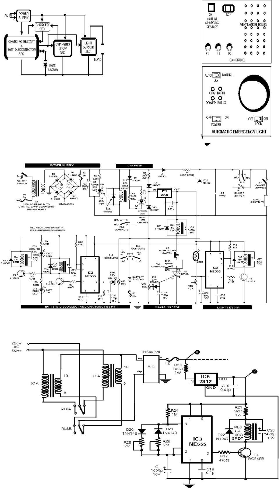
9 Emergency Light Click here for the circuit diagram The circuit of automatic emergency light presented here has the following features: 1. When the mains supply (230V AC) is available, it charges a 12V battery up to 13.5V and then the battery is disconnected from the charging section. 2. When the battery discharges up to 10.2V, it is disconnected from the load and the charging process is resumed. 3. If the mains voltage is available and there is darkness in the room, load (bulb or tube) is turned on by taking power from the mains; otherwise the battery is connected to the load. 4. When the battery discharges up to 10.2V and if the mains is not yet available, the battery is completely disconnected from the circuit to avoid its further discharge. The mains supply of 230V AC is stepped down to 18V AC (RMS) using a 230V AC primary to 0-18V AC, 2A secondary transformer (X1), generally used in 36cm B&W TVs. Diodes D1 through D4 form bridge rectifier and capacitor C5 filters the voltage, providing about 25V DC at the output. Charging section includes 33-ohm, 10- watt resistor R2 which limits the charging current to about 425 ma when battery voltage is about 10.2V, or to 325 ma when battery voltage is about 13.5V. When the battery charges to 13.5V (as set by VR2), zener diode D17 goes into breakdown region, thereby triggering triac TR1. Now, since DC is passing through the triac, it remains continuously on even if the gate current is reduced to zero (by disconnecting the gate terminal). Once the battery is fully charged, charging section is cut-off from the battery due to energisation of relay RL2. This relay remains on even if the power fails because of connection to the battery via diode D10. S4, a normally closed switch, is included to manually restart the charging process if required. Battery disconnect and charging restart section comprises an NE555 timer (IC2) wired in monostable mode. When the battery voltage is above 10.2V (as indicated by red LED D15), zener diode (D16) remains in the breakdown region, making the trigger pin 2 of IC2 high, thereby maintaining output pin 3 in low voltage state. Thus, relay RL3 is on and relay RL4 is off. But as soon as the battery voltage falls to about 10.2V (as set by preset VR1), zener diode D16 comes out of conduction, making pin 2 low and pin 3 high to turn on relay RL4 and orange LED D13. This also switches off relay RL3 and LED D15. Now, if the mains is available, charging restarts due to de-energisation of relay RL2 because when relay RL4 is on, it breaks the circuit of relay RL2 and triac TR1. But if the mains supply is not present, both relays RL3 and RL1 de-energise, disconnecting the battery from the remaining circuit. Thus when battery voltage falls to 10.2 volts, its further discharge is eliminated. But as
 is turned on by taking power from the mains; otherwise the battery is connected to the load. 4.")
10 soon as the mains supply resumes, it energises relay RL1, thereby connecting the battery again to the circuit. Light sensor section also makes use of a 555 timer IC in the monostable mode. As long as normal light is falling on LDR1, its resistance is comparatively low. As a result pin 2 of IC3 is held near Vcc and its output at pin 3 is at low level. In darkness, LDR resistance is very high, which causes pin 2 of IC3 to fall to near ground potential and thus trigger it. As a consequence, output pin 3 goes high during the monostable pulse period, forward biasing transistor T3 which goes into saturation, energising relay RL5. With auto/bypass switch S2 off (in auto mode), the load gets connected to supply via switch S3. If desired, the load may be switched during the day-time by flipping switch S2 to on position (manual). Preset VR3 is the sensitivity control used for setting threshold light level at which the load is to be automatically switched on/off. Capacitors with the relays ensure that there is no chattering of the relays. When the mains is present, diode D8 couples the input voltage to regulator IC1 whereas diode D10 feeds the input voltage to it (from battery) in absense of mains supply. Diode D5 connects the load to the power supply section via resistor R5 when mains is available (diode D18 does not conduct). However, when mains power fails, the situation reverses and diode D18 conducts while diode D5 does not conduct.. The load can be any bulb of 12 volts with a maximum current rating of 2 amperes (24 watts). Resistor R5 is supposed to drop approximately 12 volts when the load current flows through it during mains availability. Hence power dissipated in it would almost be equal to the load power. It is therefore desirable to replace R5 with a bulb of similar voltage and wattage as the load so that during mains availability we have more (double) light than when the load is fed from the battery. For setting presets VR1 and VR2, just take out (desolder one end) diodes D7, D10 and D18. Connect a variable source of power supply in place of battery. Set preset VR1 so that battery-high LED D15 is just off at 10.2V of the variable source. Increase the potential of the variable source and observe the shift from LO BAT LED D13 to D15. Now make the voltage of the source 13.5V and set preset VR2 so that relay RL2 just energises. Then decrease the voltage slowly and observe that relay RL2 does not de-energise above 10.2V. At 10.2V, LED D15 should be off and relay RL2 should de-energise while LED D13 should light up. Preset VR3 can be adjusted during evening hours so that the load is on during the desired light conditions

11
12 Automatic Room Lights Click here for the circuit diagram An ordinary automatic room power control circuit has only one light sensor. So when a person enters the room it gets one pulse and the lights come on. When the person goes out it gets another pulse and the lights go off. But what happens when two persons enter the room, one after the other? It gets two pulses and the lights remain in off state. The circuit described here overcomes the above-mentioned problem. It has a small memory which enables it to automatically switch on and switch off the lights in a desired fashion. The circuit uses two LDRs which are placed one after another (separated by a distance of say half a metre) so that they may separately sense a person going into the room or coming out of the room. Outputs of the two LDR sensors, after processing, are used in conjunction with a bicolour LED in such a fashion that when a person gets into the room it emits green light and when a person goes out of the room it emits red light, and vice versa. These outputs are simultaneously applied to two counters. One of the counters will count as +1, +2, +3 etc when persons are getting into the room and the other will count as -1, -2, -3 etc when persons are getting out of the room. These counters make use of Johnson decade counter CD4017 ICs. The next stage comprises two logic ICs which can combine the outputs of the two counters and determine if there is any person still left in the room or not. Since in the circuit LDRs have been used, care should be taken to protect them from ambient light. If desired, one may use readily available IR sensor modules to replace the LDRs. The sensors are installed in such a way that when a person enters or leaves the room, he intercepts the light falling on them sequentially one after the other. When a person enters the room, first he would obstruct the light falling on LDR1, followed by that falling on LDR2. When a person leaves the room it will be the other way round. In the normal case light keeps falling on both the LDRs, and as such their resistance is low (about 5 kilo-ohms). As a result, pin 2 of both timers (IC1 and IC2), which have been configured as monostable flip-flops, are held near the supply voltage (+9V). When the light falling on the LDRs is obstructed, their resistance becomes very high and pin 2 voltages drop to near ground potential, thereby triggering the flip-flops. Capacitors across pin 2 and ground have been added to avoid false triggering due to electrical noise. When a person enters the room, LDR1 is triggered first and it results in triggering of monostable IC1. The short output pulse immediately charges up capacitor C5, forward biasing transistor pair T1-T2. But at this instant the collectors of transistors T1 and T2 are in high impedance state as IC2 pin 3 is at low potential and diode D4 is not conducting. But when the same person passes LDR2, IC2 monostable flip-flop is triggered. Its pin 3 goes high and this potential is coupled to transistor pair T1-T2 via diode D4. As a result transistor pair T1-T2 conducts because capacitor C5 retains the charge for some time as its discharge time is controlled by resistor R5 (and R7 to an extent). Thus green LED portion of bi-colour LED is lit momentarily. The same output is also coupled to IC3 for which it acts as a clock. With entry of each person IC3 output (high state) keeps advancing. At this stage transistor pair T3-T4 cannot conduct because output pin 3 of IC1 is no longer positive as its output pulse duration is quite short and hence transistor collectors are in high impedance state. When persons leave the room, LDR2 is triggered first followed by LDR1. Since the bottom half portion of circuit is identical to top half, this time with the departure of each person red portion of bi-colour LED is lit momentarily and output of IC4 advances in the same fashion as in case of IC3. The outputs of IC3 and those of IC4 (after inversion by inverter gates N1 through N4) are ANDed by AND gates (A1 through A4) are then wire ORed (using diodes D5 through D8). The net effect is that when persons are entering, the output of at least one of the AND gates is high, causing transistor T5 to conduct and energise relay RL1. The bulb connected to the supply via N/O contact of relay RL1 also lights up. When persons are leaving the room, and till all the persons who entered the room have left, the wired OR output continues to remain high, i.e. the bulb continues to remains on, until all persons who entered the room have left. The maximum number of persons that this circuit can handle is limited to four since on receipt of fifth clock pulse the counters are reset. The capacity of the circuit can be easily extended for up to nine persons by removing the connection of pin 1 from reset pin (15) and utilising Q1 to Q9 outputs of CD4017 counters. Additional inverters, AND gates and diodes will, however, be required

13 Negative Supply from single positive Supply -Naveen P N Click here for the circuit diagram Opamps are very useful. But one of their major drawbacks is the requirement of a dual supply. This seriously limits their applications in fields where a dual supply is not affordable or not practicable. This circuit solves the problem to a certain extent. It provides a negative voltage from a single positive supply. This negative voltage together with the positive supply can be used to power the opamps and other circuits requiring a dual supply. The circuits operation can be explained as follows: The 555 IC is operating as an astable multivibrator with a frequency of about 1kHz. A square wave is obtained at the pin 3 of the IC. When the output is positive, the 22uF capacitor charges through the diode D1. When the output at pin 3 is ground, the 22uF discharges through the diode D2 and charges the 100uF capacitor is charged. The output is taken across the 100uF capacitor as shown in the figure. A disadvantage of this circuit is its poor voltage regulation and current limit. The max. current that can be drawn from this circuit is about 40mA. If you draw more current, the regulation will be lost. Also the output negative voltage will be a little less than the positive supply due to the diode drops. For example if the voltage is +9V then the output voltage will be about 7.5 V.

14 Self switching Power Supply Click here for the circuit diagram One of the main features of the regulated power supply circuit being presented is that though fixed-voltage regulator LM7805 is used in the circuit, its output voltage is variable. This is achieved by connecting a potentiometer between common terminal of regulator IC and ground. For every 100-ohm increment in the incircuit value of the resistance of potentiometer VR1, the output voltage increases by 1 volt. Thus, the output varies from 3.7V to 8.7V (taking into account 1.3-volt drop across diodes D1 and D2). Another important feature of the supply is that it switches itself off when no load is connected across its output terminals. This is achieved with the help of transistors T1 and T2, diodes D1 and D2, and capacitor C2. When a load is connected at the output, potential drop across diodes D1 and D2 (approximately 1.3V) is sufficient for transistors T2 and T1 to conduct. As a result, the relay gets energised and remains in that state as long as the load remains connected. At the same time, capacitor C2 gets charged to around 7-8 volt potential through transistor T2. But when the load is disconnected, transistor T2 is cut off. However, capacitor C2 is still charged and it starts discharging through base of transistor T1. After some time (which is basically determined by value of C2), relay RL1 is de-energised, which switches off the mains input to primary of transformer X1. To resume the power again, switch S1 should be pressed momentarily. Higher the value of capacitor C2, more will be the delay in switching off the power supply on disconnection of the load, and vice versa. Though in the prototype a transformer with a secondary voltage of 12V-0V, 250mA was used, it can nevertheless be changed as per user s requirement (up to 30V maximum. and 1-ampere current rating). For drawing more than 300mA current, the regulator IC must be fitted with a small heat sink over a mica insulator. When the transformer s secondary voltage increases beyond 12 volts (RMS), potentiometer VR1 must be redimensioned. Also, the relay voltage rating should be redetermined. Over / Under Voltage Cut-Out Click here for the circuit diagram This over/under voltage cut-out will save your costly electrical and electronic appliances from the adverse effects of very high and very low mains voltages. The circuit features auto reset and utilises easily available components. It makes use of the comparators available inside 555 timer ICs. Supply is tapped from different points of the power supply circuit for relay and control circuit operation to achieve reliability. The circuit utilises comparator 2 for control while comparator 1 output (connected to reset pin R) is kept low by shorting pins 5 and 6 of 555 IC. The positive input pin of comparator 2 is at 1/3rd of Vcc voltage. Thus as long as negative input pin 2 is less positive than 1/3 Vcc, comparator 2 output is high and the internal flip-flop is set, i.e. its Q output (pin 3) is high. At the same time pin 7 is in high impedance state and LED connected to pin 7 is therefore off. The output (at pin 3) reverses (goes low) when pin 2 is taken more positive than 1/3 Vcc. At the same time pin 7 goes low (as Q ouptput* of internal flip- flop is high) and the LED connected to pin 7 is
. Another important feature of the supply is that it switches itself off when no load is connected across its output terminals.")
15 lit. Both timers (IC1 and IC2) are configured to function in the same fashion. Preset VR1 is adjusted for under voltage (say 160 volts) cut-out by observing that LED1 just lights up when mains voltage is slightly greater than 160V AC. At this setting the output at pin 3 of IC1 is low and transistor T1 is in cut-off state. As a result RESET* pin 4 of IC2 is held high since it is connected to Vcc via 100 kilo-ohm resistor R4. Preset VR2 is adjusted for over voltage (say 270V AC) cut-out by observing that LED2 just extinguishes when the mains voltage is slightly less than 270V AC. With RESET* pin 4 of IC2 high, the output pin 3 is also high. As a result transistor T2 conducts and energises relay RL1, connecting load to power supply via its N/O contacts. This is the situation as long as mains voltage is greater than 160V AC but less than 270V AC. When mains voltage goes beyond 270V AC, it causes output pin 3 of IC2 to go low and cut-off transistor T2 and deenergise relay RL1, in spite of RESET* pin 4 still being high. When mains voltage goes below 160V AC, IC1 s pin 3 goes high and LED1 is extinguished. The high output at pin 3 results in conduction of transistor T1. As a result collector of transistor T1 as also RESET* pin 4 of IC2 are pulled low. Thus output of IC2 goes low and transistor T2 does not conduct. As a result relay RL1 is de-energised, which causes load to be disconnected from the supply. When mains voltage again goes beyond 160V AC (but less than 270V AC) the relay again energises to connect the load to power supply High and Low Voltage Cutout with delay and Music Click here for the circuit diagram Voltage variations and power cuts adversely affect various equip- ment such as TVs, VCRs, music systems and refrigerators. This simple circuit will protect the costly equipment from high as well as low voltages and the voltage surges (when power resumes). It also gives a melodious tune when mains power resumes. When mains voltage is normal, the DC voltage at the cathode of zener diode D4 is less then 5.6V. As a result transistor T1 is in off state. The DC voltage at the cathode of zener diode D5 is greater than 5.6V and as a result transistor T2 is in on state. Consequently, relay RL1 gets energised, which is indicated by lighting up of green LED. Under high mains voltage condition, transistor T1 switches to on state because the voltage at cathode of zener diode D4 becomes greater than 5.6V. Consequently, transistor T2 switches to off state, making the relay to de-energise Under low mains voltage condition, transistor T1 switches to off state and as a result transistor T2 also switches to off state, making the relay to de-energise. Timer IC 555 in the circuit is configured to operate in a monostable mode. The pulse width is about 10 seconds with the timing component values used in the circuit. When the power resumes after a break, pin 2 of IC 555 goes low briefly and this triggers it. Its output makes music IC UM66 to operate through transistor T3. Simultaneously, transistor T1 also gets forward biased as the monostable IC1 output is connected to its base via diode D8 and resistor R7. As a result, transistor T1 conducts and biases transistor T2 to cut off. Thus relay RL1 remains de-energised for the duration of mono pulse and the load is protected against the
 cut-out by observing that LED2 just extinguishes when the mains voltage is slightly less than 270V AC.")
16 voltage surges. To adjust presets VR1 and VR2, you may use a manually variable auto-transformer. Set the output of autotransformer to 270V AC and connect it to the primary of transformer X1. Adjust preset VR1 such that relay RL1 just de-energises. Next set the output of auto-transformer to 170V AC. Now adjust preset VR2 such that relay RL1 again de-energises. Volume control VR3 may be adjusted for the desired output volume of the tune generated by IC UM66 Simple Car Battery Charger -Naveen P N Click here for the circuit diagram This very simple circuit uses a transformer,two diodes, a capacitor and an ammeter. To charge a battery just connect the + and - terminals of the circuit to the corresponding terminals of the battery. When the battery is not charged, the ammeter reading shows 1-3 amps. When the battery is fully charged the ammeter reads Zero or nearly zero, after which the battery should be removed from the charger. The circuit is a full wave rectifier using 2 diodes for rectification. The capacitor is used for smoothing. I think the circuit works fine without the capacitor since the battery itself acts a BIG capacitor. But when you are using the circuit to supply 12V (as a battery eliminator) the capacitor needs to be present. Care should be taken NOT to reverse the + and - terminals while connecting it to the battery.

17 Remote control using VHF modules Click here for the circuit diagram A few designs for remote control switches, using VG40T and VG40R remote control pair, are shown here. The miniature transmitter module shown in Fig. 1, which just measures 34 mm x 29 mm x 10 mm, can be used to operate all remote control receiver-cum-switch combinations described in this project. A compact 9-volt PP3 battery can be used with the transmitter. It can transmit signals up to 15 metres without any aerial. The operating frequency of the transmitter is 300 MHz. The following circuits, using VG40R remote control receiver module measuring 45 mm x 21 mm x 13 mm, can be used to: (a) activate a relay momentarily, (b) activate a relay for a preset period, (c) switch on and switch off a load. To activate a relay momentarily (see Fig. 2), the switch on the transmitter unit is pressed, and so a positive voltage is obtained at output pin of VG40R module. This voltage is given to bias the relay driver transistor. The relay gets activated by just pressing push-toon micro switch on the transmitter unit. The relay remains energised as long as the switch remains pressed. When the switch is released, the relay gets deactivated. Any electrical/electronic load can be connected via N/O contacts of the relay. To activate a relay for a preset period (refer Fig. 3), the switch on the transmitter unit is pressed momentarily. The transistor gets base bias from VG40R module. As a result the transistor conducts and applies a trigger pulse to IC 555, which is wired as a monostable multivibrator. The relay remains activated till the preset time is over. Time delay can be varied from a few seconds to a few minutes by adjusting timing components. To switch on and switch off a load (refer Fig. 4), a 555 IC and a decade counter 4017 IC are used. Here the 4017 IC is wired as a flip-flop for toggle action. This is achieved by connecting Q2 output to reset terminal while Q1 output is unused. Q0 output is used for energising the relay. The relay is activated and deactivated by pressing the transmitter switch alternately. So, to activate the load, just press the transmitter switch once, momentarily. The relay will remain activated. To switch off the relay, press the transmitter switch again. This process can be repeated. Time delay of monostable multivibrator is set for about one second.
 activate a relay momentarily, (b) activate a relay for a preset period, (c)")
18 Note: Short length of shielded wire should be used between VG40R receiver module output and the rest of the circuit. The transmitter with 9V battery must be housed inside a nonmetallic (say, plastic) cabinet for maximum range of operation.
 cabinet for maximum range of")
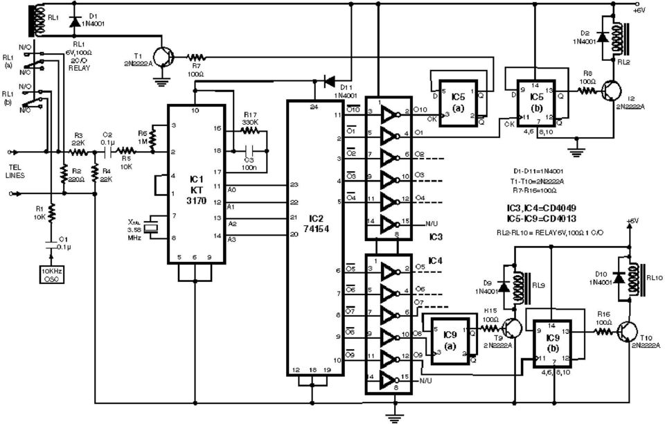
19 Remote control using telephone Click here for the circuit diagram Here is a teleremote circuit which enables switching on and off of appliances through telephone lines. It can be used to switch appliances from any distance, overcoming the limited range of infrared and radio remote controls. The circuit described here can be used to switch up to nine appliances (corresponding to the digits 1 through 9 of the telephone key-pad). The DTMF signals on telephone instrument are used as control signals. The digit 0 in DTMF mode is used to toggle between the appliance mode and normal telephone operation mode. Thus the telephone can be used to switch on or switch off the appliances also while being used for normal conversation. The circuit uses IC KT3170 (DTMF-to-BCD converter), (4-to-16-line demultiplexer), and five CD4013 (D flip-flop) ICs. The working of the circuit is as follows. Once a call is established (after hearing ring-back tone), dial 0 in DTMF mode. IC1 decodes this as 1010, which is further demultiplexed by IC2 as output O10 (at pin 11) of IC2 (74154). The active low output of IC2, after inversion by an inverter gate of IC3 (CD4049), becomes logic 1. This is used to toggle flip-flop-1 (F/F-1) and relay RL1 is energised. Relay RL1 has two changeover contacts, RL1(a) and RL1(b). The energised RL1(a) contacts provide a 220-ohm loop across the telephone line while RL1(b) contacts inject a 10kHz tone on the line, which indicates to the caller that appliance mode has been selected. The 220-ohm loop on telephone line disconnects the ringer from the telephone line in the exchange. The line is now connected for appliance mode of operation. If digit 0 is not dialed (in DTMF) after establishing the call, the ring continues and the telephone can be used for normal conversation. After selection of the appliance mode of operation, if digit 1 is dialed, it is decoded by IC1 and its output is This BCD code is then demultiplexed by 4-to-16-line demultiplexer IC2 whose corresponding output, after inversion by a CD4049 inverter gate, goes to logic 1 state. This pulse toggles the corresponding flip-flop to alternate state. The flip-flop output is used to drive a relay (RL2) which can switch on or switch off the appliance connected through its contacts. By dialing other digits in a similar way, other appliances can also be switched on or off. Once the switching operation is over, the 220-ohm loop resistance and 10kHz tone needs to be removed from the telephone line. To achieve this, digit 0 (in DTMF mode) is dialed again to toggle flip-flop-1 to de-energise relay RL1, which terminates the loop on line and the 10kHz tone is also disconnected. The telephone line is thus again set free to receive normal calls.this circuit is to be connected in parallel to the telephone instrument

20
GLOLAB Universal Telephone Hold
 GLOLAB Universal Telephone Hold 1 UNIVERSAL HOLD CIRCUIT If you have touch tone telephone service, you can now put a call on hold from any phone in the house, even from cordless phones and phones without
1. Learn about the 555 timer integrated circuit and applications 2. Apply the 555 timer to build an infrared (IR) transmitter and receiver
 transmitter and receiver") Electronics Exercise 2: The 555 Timer and its Applications Mechatronics Instructional Laboratory Woodruff School of Mechanical Engineering Georgia Institute of Technology Lab Director: I. Charles Ume,
Electronics Exercise 2: The 555 Timer and its Applications Mechatronics Instructional Laboratory Woodruff School of Mechanical Engineering Georgia Institute of Technology Lab Director: I. Charles Ume,
GLOLAB Two Wire Stepper Motor Positioner
 Introduction A simple and inexpensive way to remotely rotate a display or object is with a positioner that uses a stepper motor to rotate it. The motor is driven by a circuit mounted near the motor and
HAM841K ALARM CONTROL PANEL FOR COMMERCIAL AND RESIDENTIAL SECURITY SYSTEMS
 ALARM CONTROL PANEL FOR COMMERCIAL AND RESIDENTIAL SECURITY SYSTEMS USER MANUAL USER MANUAL ALARM CONTROL PANEL FOR COMMERCIAL AND RESIDENTIAL SECURITY SYSTEMS INTRODUCTION The (HA-841K) is a complete
Glolab Talking Phone Dial Monitor
 Introduction The detects the tones generated when numbers are dialed on your touch tone telephone and speaks the numbers that were dialed. This verifies that you dialed the correct number and is especially
Development of a Simple Sound Activated Burglar Alarm System
 [ Leonardo Journal of Sciences ISSN 1583-0233 Issue 9, July-December 2006 p. 97-102 Development of a Simple Sound Activated Burglar Alarm System Department of Electrical and Computer Engineering, Federal
ARRL Morse Code Oscillator, How It Works By: Mark Spencer, WA8SME
 The national association for AMATEUR RADIO ARRL Morse Code Oscillator, How It Works By: Mark Spencer, WA8SME This supplement is intended for use with the ARRL Morse Code Oscillator kit, sold separately.
Optical Sensor Interface for AFX Digital LED Timer/Counter by George Warner, Jan. 2003 warnergt@ptd.net
 Optical Sensor Interface for AFX Digital LED Timer/Counter by George Warner, Jan. 200 warnergt@ptd.net Abstract This paper presents a design for an optical sensor interface to an AFX Digital LED Timer/Counter.
Wires & Connections Component Circuit Symbol Function of Component. Power Supplies Component Circuit Symbol Function of Component
 Lista Dei Simboli Dei Circuiti Per i Componenti Elettronici Wires & Connections Wire Wires joined Wires not joined To pass current very easily from one part of a circuit to another. A 'blob' should be
If an occupancy of room is zero, i.e. room is empty then light source will be switched off automatically
 EE389 Electronic Design Lab Project Report, EE Dept, IIT Bombay, Nov 2009 Fully-automated control of lighting and security system of a Room Group No: D2 Bharat Bhushan (06d04026) Sravan
CHAPTER 11: Flip Flops
 CHAPTER 11: Flip Flops In this chapter, you will be building the part of the circuit that controls the command sequencing. The required circuit must operate the counter and the memory chip. When the teach
PS 29M DUAL CHANNEL BELTPACK IN METAL CASE
 PS 29M DUAL CHANNEL BELTPACK IN METAL CASE USER MANUAL October 2013 This product is designed and manufactured by: ASL Intercom BV Zonnebaan 42 3542 EG Utrecht The Netherlands Phone: +31 (0)30 2411901 Fax:
Having read this workbook you should be able to: recognise the arrangement of NAND gates used to form an S-R flip-flop.
 Objectives Having read this workbook you should be able to: recognise the arrangement of NAND gates used to form an S-R flip-flop. describe how such a flip-flop can be SET and RESET. describe the disadvantage
Application Note AN-1068 reva
 Application Note AN-1068 reva Considerations for Designs Using Radiation-Hardened Solid State Relays By Alan Tasker Table of Contents Introduction Page Overview...1 The Contact...1 Actuation...1 The IR
Small Scale Renewable Energy Control Systems
 Small Scale Renewable Energy Control Systems Brent Crowhurst Renewable Energy Program Coordinator Falls Brook Centre, New Brunswick, Canada Nordic Folkecenter for Renewable Energy November 2006 - April
Yrd. Doç. Dr. Aytaç Gören
 H2 - AC to DC Yrd. Doç. Dr. Aytaç Gören ELK 2018 - Contents W01 Basic Concepts in Electronics W02 AC to DC Conversion W03 Analysis of DC Circuits W04 Transistors and Applications (H-Bridge) W05 Op Amps
LM 358 Op Amp. If you have small signals and need a more useful reading we could amplify it using the op amp, this is commonly used in sensors.
 LM 358 Op Amp S k i l l L e v e l : I n t e r m e d i a t e OVERVIEW The LM 358 is a duel single supply operational amplifier. As it is a single supply it eliminates the need for a duel power supply, thus
Study Guide for the Electronics Technician Pre-Employment Examination
 Bay Area Rapid Transit District Study Guide for the Electronics Technician Pre-Employment Examination INTRODUCTION The Bay Area Rapid Transit (BART) District makes extensive use of electronics technology
Kit 106. 50 Watt Audio Amplifier
 Kit 106 50 Watt Audio Amplifier T his kit is based on an amazing IC amplifier module from ST Electronics, the TDA7294 It is intended for use as a high quality audio class AB amplifier in hi-fi applications
AC-115 Compact Networked Single Door Controller. Installation and User Manual
 AC-115 Compact Networked Single Controller Installation and User Manual December 2007 Table of Contents Table of Contents 1. Introduction...5 1.1 Key Features... 6 1.2 Technical Specifications... 7 2.
DET Practical Electronics (Intermediate 1)
") DET Practical Electronics (Intermediate 1) 731 August 2000 HIGHER STILL DET Practical Electronics (Intermediate 1) Support Materials CONTENTS Section 1 Learning about Resistors Section 2 Learning about
DET Practical Electronics (Intermediate 1) 731 August 2000 HIGHER STILL DET Practical Electronics (Intermediate 1) Support Materials CONTENTS Section 1 Learning about Resistors Section 2 Learning about
POWER SUPPLY MODEL XP-15. Instruction Manual ELENCO
 POWER SUPPLY MODEL XP-15 Instruction Manual ELENCO Copyright 2013 by Elenco Electronics, Inc. REV-A 753020 All rights reserved. No part of this book shall be reproduced by any means; electronic, photocopying,
Regulated D.C. Power Supply
 442 17 Principles of Electronics Regulated D.C. Power Supply 17.1 Ordinary D.C. Power Supply 17.2 Important Terms 17.3 Regulated Power Supply 17.4 Types of Voltage Regulators 17.5 Zener Diode Voltage Regulator
Experiment # 9. Clock generator circuits & Counters. Eng. Waleed Y. Mousa
 Experiment # 9 Clock generator circuits & Counters Eng. Waleed Y. Mousa 1. Objectives: 1. Understanding the principles and construction of Clock generator. 2. To be familiar with clock pulse generation
Build The Universal Alarm System
 Build The Universal Alarm System Nothing has more appeal than a universal alarm system that can be used everywhere and is very affordable! Like most of you, I work for a living. What I like to do is to
3-Digit Counter and Display
 ECE 2B Winter 2007 Lab #7 7 3-Digit Counter and Display This final lab brings together much of what we have done in our lab experiments this quarter to construct a simple tachometer circuit for measuring
Fig 3. PLC Relay Output
 1. Function of a PLC PLC Basics A PLC is a microprocessor-based controller with multiple inputs and outputs. It uses a programmable memory to store instructions and carry out functions to control machines
Ignition Alert Anti-Theft Security System for Motorbikes with Remote Control Amit Yadav, Anushri Jha, Neelesh Gupta amitrinku007@yahoo.
 Ignition Alert Anti-Theft Security System for Motorbikes with Remote Control Amit Yadav, Anushri Jha, Neelesh Gupta amitrinku007@yahoo.com Abstract There are many vehicle security system are available
COMBINATIONAL and SEQUENTIAL LOGIC CIRCUITS Hardware implementation and software design
 PH-315 COMINATIONAL and SEUENTIAL LOGIC CIRCUITS Hardware implementation and software design A La Rosa I PURPOSE: To familiarize with combinational and sequential logic circuits Combinational circuits
Low Cost Pure Sine Wave Solar Inverter Circuit
 Low Cost Pure Sine Wave Solar Inverter Circuit Final Report Members: Cameron DeAngelis and Luv Rasania Professor: Yicheng Lu Advisor: Rui Li Background Information: Recent rises in electrical energy costs
AUTOMATIC NIGHT LAMP WITH MORNING ALARM USING MICROPROCESSOR
 AUTOMATIC NIGHT LAMP WITH MORNING ALARM USING MICROPROCESSOR INTRODUCTION This Project "Automatic Night Lamp with Morning Alarm" was developed using Microprocessor. It is the Heart of the system. The sensors
A Practical Guide to Free Energy Devices
 A Practical Guide to Free Energy Devices Device Patent No 29: Last updated: 7th October 2008 Author: Patrick J. Kelly This is a slightly reworded copy of this patent application which shows a method of
Power Supplies. 1.0 Power Supply Basics. www.learnabout-electronics.org. Module
 Module 1 www.learnabout-electronics.org Power Supplies 1.0 Power Supply Basics What you ll learn in Module 1 Section 1.0 Power Supply Basics. Basic functions of a power supply. Safety aspects of working
A Digital Timer Implementation using 7 Segment Displays
 A Digital Timer Implementation using 7 Segment Displays Group Members: Tiffany Sham u2548168 Michael Couchman u4111670 Simon Oseineks u2566139 Caitlyn Young u4233209 Subject: ENGN3227 - Analogue Electronics
Universidad Interamericana de Puerto Rico Recinto de Bayamón Escuela de Ingeniería Departamento de Ingeniería Eléctrica
 Universidad Interamericana de Puerto Rico Recinto de Bayamón Escuela de Ingeniería Departamento de Ingeniería Eléctrica Inventario de Materiales Edificio: Escuela de Ingeniería Oficina o Salón: G-221 Descripción(Circuitos
Chapter 9 Latches, Flip-Flops, and Timers
 ETEC 23 Programmable Logic Devices Chapter 9 Latches, Flip-Flops, and Timers Shawnee State University Department of Industrial and Engineering Technologies Copyright 27 by Janna B. Gallaher Latches A temporary
NTE2053 Integrated Circuit 8 Bit MPU Compatible A/D Converter
 NTE2053 Integrated Circuit 8 Bit MPU Compatible A/D Converter Description: The NTE2053 is a CMOS 8 bit successive approximation Analog to Digital converter in a 20 Lead DIP type package which uses a differential
Type SA-1 Generator Differential Relay
 ABB Automation Inc. Substation Automation and Protection Division Coral Springs, FL 33065 Instruction Leaflet 41-348.11C Effective: November 1999 Supersedes I.L. 41-348.11B, Dated August 1986 ( ) Denotes
User and installation manual
 User and installation manual aquaero 5 The information contained in this manual is subject to change without prior notice. All rights reserved. Current as of April 2011 ENGLISH: PAGE 1 DEUTSCH: SEITE 13
3 Slot Payphone Controller
 5A2 3 Slot Payphone Controller The 3 Slot Payphone -- Part of American History Building a Coin Relay Controller Version S1BX Instruction Manual and Safety Precautions It is very important that for your
Build A Video Switcher. Reprinted with permission from Electronics Now Magazine September 1997 issue
 Build A Video Switcher Reprinted with permission from Electronics Now Magazine September 1997 issue Copyright Gernsback Publications, Inc.,1997 BUILD A VIDEO SWITCHER FRANK MONTEGARI Watch several cameras
css Custom Silicon Solutions, Inc.
 css Custom Silicon Solutions, Inc. CSS555(C) CSS555/ PART DESCRIPTION The CSS555 is a micro-power version of the popular 555 Timer IC. It is pin-for-pin compatible with the standard 555 timer and features
500r+ Installation and User Guide
 500r+ Installation and User Guide Compatible Equipment 502rUK-50 Watch/Pendant PA. 509rUK-50 Smoke Detector 515rUK-00 10 metre passive infra red movement detector. 525rUK-00 Remote Set/Unset (Full and
Firmware version: 1.10 Issue: 7 AUTODIALER GD30.2. Instruction Manual
 Firmware version: 1.10 Issue: 7 AUTODIALER GD30.2 Instruction Manual Firmware version: 2.0.1 Issue: 0.6 Version of the GPRS transmitters configurator: 1.3.6.3 Date of issue: 07.03.2012 TABLE OF CONTENTS
ATS-505. GB Version 1
 ATS-505 GB Version 1 Control Locations Power/Sleep Power On/off/Alarm off/sleep function Display Switch between radio frequency and time while radio is power on Mode Mode set up (please see below mode
Res. J. Appl. Sci. Eng. Technol., 8(24): 2439-2450, 2014
: 2439-2450, 2014") Research Journal of Applied Sciences, Engineering and Technology 8(24): 2439-2450, 2014 ISSN: 2040-7459; e-issn: 2040-7467 Maxwell Scientific Organization, 2014 Submitted: September 22, 2014 Accepted:
Research Journal of Applied Sciences, Engineering and Technology 8(24): 2439-2450, 2014 ISSN: 2040-7459; e-issn: 2040-7467 Maxwell Scientific Organization, 2014 Submitted: September 22, 2014 Accepted:
ECEN 1400, Introduction to Analog and Digital Electronics
 ECEN 1400, Introduction to Analog and Digital Electronics Lab 4: Power supply 1 INTRODUCTION This lab will span two lab periods. In this lab, you will create the power supply that transforms the AC wall
Single Transistor FM Transmitter Design
 Single Transistor FM Transmitter Design In telecommunications, frequency modulation (FM) conveys information over a carrier wave by varying its frequency. FM is commonly used at VHF radio frequencies for
BUILD YOUR OWN RC SWITCH (Issue 3)
") PART ONE SINGLE ELECTRONIC RC SWITCH Fancy switching the lights using your radio, then here is a circuit you may consider building. It only uses one IC and seven other components for a single switch and
PART ONE SINGLE ELECTRONIC RC SWITCH Fancy switching the lights using your radio, then here is a circuit you may consider building. It only uses one IC and seven other components for a single switch and
Design and Construction of Microcontroller- Based Telephone Exchange System
 Design and Construction of Microcontroller- Based Telephone Exchange System Aye Sandar Win Abstract This paper demonstrates design and construction of microcontroller-based telephone exchange system and
Location-Aware and Safer Cards: Enhancing RFID Security and Privacy
 Location-Aware and Safer Cards: Enhancing RFID Security and Privacy 1 K.Anudeep, 2 Mrs. T.V.Anantha Lakshmi 1 Student, 2 Assistant Professor ECE Department, SRM University, Kattankulathur-603203 1 anudeepnike@gmail.com,
Collision Vigilant With Automatic Dialer
 International Journal of Engineering and Advanced Technology (IJEAT) ISSN: 2249 8958, Volume-2, Issue-1, October 2012 Collision Vigilant With Automatic Dialer C.Swetha, S.Suganya, V.Shobana, S.Sivaranjini,
DS1621 Digital Thermometer and Thermostat
 Digital Thermometer and Thermostat www.dalsemi.com FEATURES Temperature measurements require no external components Measures temperatures from 55 C to +125 C in 0.5 C increments. Fahrenheit equivalent
WD-AMX Water Detection Controllers
 Page 1 of 5 WD-AMX Water Detection Controllers Features: Benefit: LED Status of leak status VFC output Audible alarm Auto or manual reset alarm output Uses an isolated AC signal which prevents oxidation
Dashboard Digital Voltmeter
 Dashboard Digital Voltmeter...November, 2002 This project is helpful to anyone who drives an automobile. I had found this project at the local libary... in an old publication. I made it and it worked fine.
Content Map For Career & Technology
 Content Strand: Applied Academics CT-ET1-1 analysis of electronic A. Fractions and decimals B. Powers of 10 and engineering notation C. Formula based problem solutions D. Powers and roots E. Linear equations
Whale 3. User Manual and Installation Guide. DC Servo drive. Contents. 1. Safety, policy and warranty. 1.1. Safety notes. 1.2. Policy. 1.3. Warranty.
 Whale 3 DC Servo drive User Manual and Installation Guide Contents 1. Safety, policy and warranty. 1.1. Safety notes. 1.2. Policy. 1.3. Warranty. 2. Electric specifications. 2.1.Operation ranges. 3. Connections
Tutorial. replace them with cell-phone operated module. The advantages of a cell-phone operated bot are:-
 Tutorial Overview: The basic aim of the project is to find an alternative to the usual RF circuits that are seen so frequently and replace them with cell-phone operated module. The advantages of a cell-phone
CMOS, the Ideal Logic Family
 CMOS, the Ideal Logic Family INTRODUCTION Let s talk about the characteristics of an ideal logic family. It should dissipate no power, have zero propagation delay, controlled rise and fall times, and have
Tube Liquid Sensor OPB350 / OCB350 Series
 Features: Can identify if liquid is present in clear tubes that have an outside diameter of 1/16 [1.6mm], 1/8" [3.2mm], 3/16" [4.8 mm] or 1/4" [6.3 mm] Opaque plastic housing enhances ambient light rejection
CM705B - Universal Expander Module CM707B - Plug On Zone Expander Security Systems
 CM705B - Universal Expander Module CM707B - Plug On Zone Expander Security Systems EN Security System CM705B CM705B - Universal Expander Module The CM705B universal expander provides a cost effective way
1R / 4-BUTTON SERIES
 Button 1 1R / 4-BUTTON SERIES VEHICLE SECURITY SYSTEM Standard Features: Two 4-Button Remote Transmitters Status indicator (LED) Valet / override switch Multi-tone siren Dual stage impact detector Remote
Automatic Telephone Dialer TD-101(W)
") Automatic Telephone Dialer TD-101(W) The TD-101 is an automatic dialing device which can transmit prerecorded information via the telephone line. The dialer can send two different 10 second voice messages
Automatic Telephone Dialer TD-101(W) The TD-101 is an automatic dialing device which can transmit prerecorded information via the telephone line. The dialer can send two different 10 second voice messages
AUTODIALLER / QUICKDIALLER - SA132
 AUTODIALLER / QUICKDIALLER - SA132 INSTRUCTION LEAFLET ENGLISH www.thermomax-group.com CONTENTS 1 SETUP AT A GLANCE... 2 2 FOREWORD....... 3 3 INSTALLATION...... 4 4 KEYPAD AND INDICATORS...... 5 SETTING
Development of a Single Phase Automatic Change-Over Switch
 Development of a Single Phase Automatic Change-Over Switch M.S. Ahmed, A.S. Mohammed and O.. Agusiobo Department of Electrical and Computer Engineering, Federal University of Technology Minna, Nigeria
Series AMLDL-Z Up to 1000mA LED Driver
 FEATURES: Click on Series name for product info on aimtec.com Series Up to ma LED Driver Models Single output Model Input Voltage (V) Step Down DC/DC LED driver Operating Temperature range 4ºC to 85ºC
DC-8706K Auto Dial Alarm System
 DC-8706K Auto Dial Alarm System User Guide Basic Contents: 1x the host unit; 1x wireless door (window) magnet; 1x wireless infrared detector; 2x remote control; 1x siren; 1x phone core; 1x AC to DC power
Wireless Home Security System
 Wireless Home Security System Group: D14 Members: Vaibhav Singh (05D07026) Abhishek Tiwari (05D07028) Sauvik Chowdhury (05D07029) 1. Abstract The project is aimed at designing a low cost and reliable wireless
A Lesson on Digital Clocks, One Shots and Counters
 A Lesson on Digital Clocks, One Shots and Counters Topics Clocks & Oscillators LM 555 Timer IC Crystal Oscillators Selection of Variable Resistors Schmitt Gates Power-On Reset Circuits One Shots Counters
MODEL 2202IQ (1991-MSRP $549.00)
") F O R T H E L O V E O F M U S I C F O R T H E L O V E O F M U S I C MODEL 2202IQ (1991-MSRP $549.00) OWNER'S MANUAL AND INSTALLATION GUIDE INTRODUCTION Congratulations on your decision to purchase a LINEAR
F O R T H E L O V E O F M U S I C F O R T H E L O V E O F M U S I C MODEL 2202IQ (1991-MSRP $549.00) OWNER'S MANUAL AND INSTALLATION GUIDE INTRODUCTION Congratulations on your decision to purchase a LINEAR
OPTICAL COMMUNICATION BASED STEPPER MOTOR CONTROL USING PULSE WIDTH MODULATION
 2011 pp 1-5 OPTICAL COMMUNICATION BASED STEPPER MOTOR CONTROL USING PULSE WIDTH MODULATION Vinayak Abrol* Department of Electronics & Communication, SSGPURC Panjab University Chandigarh, India Votrix13@gmail.com
162 CB CABLE TRACER. Filter Probe & Tone Generator INSTRUCTION MANUAL
 162 CB CABLE TRACER Filter Probe & Tone Generator INSTRUCTION MANUAL INDEX PAGE 1. INTRODUCTION... 1 2. FILTER PROBE... 1-3 3. TONE GENERATOR... 3-6 4. SPECIFICATION... 7-8 5. MAINTENANCE... 8 1. INTRODUCTION
GSM Home Alarm System User Manual. http://www.usmartbuy.com
 GSM Home Alarm System User Manual http://www.usmartbuy.com 1 1. Factory default Normally, all sensors in the big box have been coded (learnt) to the control host Operation Password: 0000 Long-Distance
step 1 Unpack the lunchbox And check whether you have got all the components~ If you have questions please contact us at: info@unitunlikely.
 step 1 Unpack the lunchbox And check whether you have got all the components~ If you have questions please contact us at: info@unitunlikely.com This part is called the PCB (printed circuit board). All
Theory of Transistors and Other Semiconductor Devices
 Theory of Transistors and Other Semiconductor Devices 1. SEMICONDUCTORS 1.1. Metals and insulators 1.1.1. Conduction in metals Metals are filled with electrons. Many of these, typically one or two per
Enhanced In-house Voice Communication over Power- Line Network
 International Journal of Scientific and Research Publications, Volume 3, Issue 7, July 2013 1 Enhanced In-house Voice Communication over Power- Line Network Asif Hassan Senior Lecturer, Dept. of ECE, HMSIT,
Shunt lock function 3066
 Version: January 2004 Contents Alarm System Activation unit Deactivation unit Digital locking cylinder or Smart Relay 1.0 Method of Operation 4 1.1 General 4 1.2 Turning the Alarm System On 4 1.3 Turning
GRADE 11A: Physics 5. UNIT 11AP.5 6 hours. Electronic devices. Resources. About this unit. Previous learning. Expectations
 GRADE 11A: Physics 5 Electronic devices UNIT 11AP.5 6 hours About this unit This unit is the fifth of seven units on physics for Grade 11 advanced. The unit is designed to guide your planning and teaching
The components. E3: Digital electronics. Goals:
 E3: Digital electronics Goals: Basic understanding of logic circuits. Become familiar with the most common digital components and their use. Equipment: 1 st. LED bridge 1 st. 7-segment display. 2 st. IC
Features. Applications
 LM555 Timer General Description The LM555 is a highly stable device for generating accurate time delays or oscillation. Additional terminals are provided for triggering or resetting if desired. In the
GSM AUTO DIALER. Remote Monitoring & Control using your mobile phone. www.gsm-activate.co.uk
 GSM AUTO DIALER Remote Monitoring & Control using your mobile phone www.gsm-activate.co.uk Product Information Our GSM Auto-Dialer is a versatile unit which can be attached to many of your electronic devices
Assembly. Integrated Circuits. DILSHAN R JAYAKODY (jayakody2000lk@gmail.com)
") DILSHAN R JAYAKODY (jayakody000lk@gmail.com) Colombo, Sri Lanka In this project we design low cost high performance programmable home security system using few LDR s as an input sensors. When above sensor(s)
DILSHAN R JAYAKODY (jayakody000lk@gmail.com) Colombo, Sri Lanka In this project we design low cost high performance programmable home security system using few LDR s as an input sensors. When above sensor(s)
LOXONE 12 Channel Amplifier
 LOXONE 12 Channel Amplifier Item no.: 200110 Thank you for purchasing the Loxone Twelve Channel Amplifier. The versatility of the Amplifier makes it the perfect choice for almost every type of custom multi-room
TX GSM SMS Auto-dial Alarm System. Installation and User Manual
 TX GSM SMS Auto-dial Alarm System Installation and User Manual Product Features: 1. 16 wireless zones, 3 wired zones alarm system, suitable for small to medium size offices and homes. 2. The system uses
DESIGN OF SMS ENABLED CAR SECURITY SYSTEM
 DESIGN OF SMS ENABLED CAR SECURITY SYSTEM K. A. Amusa Federal University of Agriculture, Abeokuta, O. O. Nuga Federal University of Agriculture, Abeokuta, A. A. Adetomi Federal University of Agriculture,
User Manual. Before installation and use, please read the user manual carefully.
 Sebury Technology Co., Ltd. Address: 5/F, Building 8, Xinwu Industrial Park, Xili, Nanshan District, Shenzhen, China. Tel: +86-755-88856 Fax: +86-755-888565 P.C.: 58055 www.sebury.com.cn User Manual Before
Multi Function, User Configurable Remote Vehicle Security System with 4 Button Replaceable Membrane Remote Transmitter
 MODEL PRO-9744 INSTALLATION MANUAL Multi Function, User Configurable Remote Vehicle Security System with 4 Button Replaceable Membrane Remote Transmitter This System Allows The Transmitter Buttons To Be
conventional system operation
 conventional system operation detection line operation Conventional detection systems normally operate on a 24VDC line. In the standby condition, the detectors will draw a low current, typically less than
Pulse Width Modulation (PWM) LED Dimmer Circuit. Using a 555 Timer Chip
 LED Dimmer Circuit. Using a 555 Timer Chip") Pulse Width Modulation (PWM) LED Dimmer Circuit Using a 555 Timer Chip Goals of Experiment Demonstrate the operation of a simple PWM circuit that can be used to adjust the intensity of a green LED by varying
Pulse Width Modulation (PWM) LED Dimmer Circuit Using a 555 Timer Chip Goals of Experiment Demonstrate the operation of a simple PWM circuit that can be used to adjust the intensity of a green LED by varying
SERVICE INSTRUCTION R410A. WALL MOUNTEDtype INVERTER SPLIT TYPE ROOM AIR CONDITIONER. Models Indoor unit Outdoor unit
 SERVICE INSTRUCTION SPLIT TYPE ROOM AIR CONDITIONER WALL MOUNTEDtype INVERTER Models Indoor unit Outdoor unit ASYG07LECA ASYG09LECA ASYG12LECA ASYG14LECA AOYG07LEC AOYG09LEC AOYG12LEC AOYG14LEC R410A CONTENTS
Programmable Single-/Dual-/Triple- Tone Gong SAE 800
 Programmable Single-/Dual-/Triple- Tone Gong Preliminary Data SAE 800 Bipolar IC Features Supply voltage range 2.8 V to 18 V Few external components (no electrolytic capacitor) 1 tone, 2 tones, 3 tones
User s Information Guide R1A
 HSC505-R Home Security Controller - User Manual Release R1a Pi HSC505 and Pi HSC505R Home Security Controller User s Information Guide R1A Page 1 QD Dynamics (Pty) Ltd reserves the right to make changes
Module 3: Floyd, Digital Fundamental
 Module 3: Lecturer : Yongsheng Gao Room : Tech - 3.25 Email : yongsheng.gao@griffith.edu.au Structure : 6 lectures 1 Tutorial Assessment: 1 Laboratory (5%) 1 Test (20%) Textbook : Floyd, Digital Fundamental
Improvements of Reliability of Micro Hydro Power Plants in Sri Lanka
 Improvements of Reliability of Micro Hydro Power Plants in Sri Lanka S S B Udugampala, V Vijayarajah, N T L W Vithanawasam, W M S C Weerasinghe, Supervised by: Eng J Karunanayake, Dr. K T M U Hemapala
A Lesson on Digital Clocks, One Shots and Counters
 A Lesson on Digital Clocks, One Shots and Counters Topics Clocks & Oscillators LM 555 Timer IC Crystal Oscillators Selection of Variable Resistors Schmitt Gates Power-On Reset Circuits One Shots Counters
NC2000 Charge Controller for Nickel-Cadmium and Nickel-Metal Hydride Batteries
 NC2000 Charge Controller for Nickel-Cadmium and Nickel-Metal Hydride Batteries General Description The NC2000 is a device designed to intelligent charge either nickel-cadmium (NiCad) or nickel-metal hydride
QUASAR ELECTRONICS KIT No. 1015 ELECTRONIC MOSQUITO REPELLER
 QUASAR ELECTRONICS KIT No. 1015 ELECTRONIC MOSQUITO REPELLER General Description This simple circuit can prove itself worth many times its value (which is very reasonable anyway) in getting rid of mosquitoes
High voltage power supply (1 to 20 KV)
") High voltage power supply ( to 0 KV) Ammar Ahmed Khan, Muhammad Wasif, Muhammad Sabieh Anwar This documentation is divided into two parts, the first part provides a brief overview about the key features
High voltage power supply ( to 0 KV) Ammar Ahmed Khan, Muhammad Wasif, Muhammad Sabieh Anwar This documentation is divided into two parts, the first part provides a brief overview about the key features
Redesigned by Laurier Gendron (Aug 2006 ) Download this project in PDF. Horn circuit. Train Circuitry
 Download this project in PDF. Horn circuit. Train Circuitry") Redesigned by Laurier Gendron (Aug 2006 ) Download this project in PDF Train Circuitry Horn circuit New Design After many comments by interested hobbyists not being able to obtain parts like the LM566
Redesigned by Laurier Gendron (Aug 2006 ) Download this project in PDF Train Circuitry Horn circuit New Design After many comments by interested hobbyists not being able to obtain parts like the LM566