INSTRUCTION BOOK. Notes on Tuning and Maintenance of Ibis Bicycles, Rev. F
|
|
|
- Doris Black
- 8 years ago
- Views:
Transcription
1 INSTRUCTION BOOK Notes on Tuning and Maintenance of Ibis Bicycles, Rev. F

2 Instruction Manual Notes on Tuning and Maintenance of Ibis Bicycles, Rev. F Reprinting Permitted if Source Quoted

3 INTRODUCTION CONTENTS Salutations This Set-Up Guide will help you with assembly tips, get you started on adjusting the suspension, maintaining your frame and explain how to perform basic mechanical jobs. This guide does not attempt to address full bike assembly, fitting, brake and shifting set-up, riding techniques etc. Please utilize a professional level service for these items to get the best performance and enjoyment from your Ibis. This Set-Up Guide is also available online with enhanced functions and additional information: Information on legacy Ibis models available at: Introduction Build Geometry/Quick Specs Sizing Guide Bike Setup Tips and Tricks Cable Routing Ride Fork Setup Fork Air Pressure Chart Rear Shock Set-Up Rear Shock Air Pressure Chart Maintain Bearing Maintenance and Replacement Frame Hardware Drawings (Part Numbers and Exploded Views) Frame Hardware Torque Spec Chart Swingarm Removal Warranty/Warranty Registration Serial Number Chuck s Recipe Contact Info Index with Video Links

4 FRAME GEOMETRY CHART New Ripley with 130mm Fork Size Medium Large Seattube A Toptube B 587mm 607mm Headtube C 94mm 100mm Chainstay D Seat Angle E Head Angle F Wheelbase G 1105mm 1125mm Stack 620mm 625mm Reach 390mm 406 mm Ripley LS Size Medium Large X-Large Seattube A Toptube B 600mm 619mm 640mm Headtube C 93mm 102mm 107mm Chainstay D Seat Angle E Head Angle F Wheelbase G 1140mm 1167mm 1187mm Stack 619mm 625mm 632mm Reach 411mm 428mm 448mm FRAME GEOMETRY CHART 29 wheels 120mm rear wheel dw-link travel Approved for mm forks, 51mm rake is STRONGLY recommended 69.2º head angle with a 130mm fork Internal cable routing using our flexible and easy to setup port system Chainstay length: 17.4 Threaded bottom bracket Shimano side swing front derailleur compatible Tapered headtube and steerer: ZS44 upper, EC49 lower 12 x 142mm Shimano rear through axle 160mm post mount left dropout, carbon fiber 29 wheels 120mm rear wheel dw-link travel Approved for mm forks, 51mm rake is STRONGLY recommended 67.5º head angle with a 130mm fork Internal cable routing using our flexible and easy to setup port system Chainstay length: 17.4 Threaded bottom bracket Shimano side swing front derailleur compatible Tapered headtube and steerer: ZS44 upper, EC49 lower 12 x 142mm Shimano rear through axle 160mm post mount left dropout, carbon fiber 4 5

5 FRAME GEOMETRY CHART Mojo HD 3 Size Small Medium Large X-Large Seattube A Toptube B 580mm 600mm 620mm 640mm Headtube C 85mm 105mm 117mm 132mm Chainstay D 430mm 430mm 430mm 430mm Seat Angle E Head Angle F Wheelbase G 1135mm 1146mm 1168mm 1189mm Stack 580mm 599mm 610mm 624mm Reach 411mm 414mm 431mm 446mm Tranny 29 Size Small Medium Large X-Large Seattube A Toptube B 564mm 584mm 605mm 625mm Headtube C 78mm 94mm 100mm 115mm Chainstay D 435mm 435mm 435mm 435mm Seat Angle E Head Angle F Wheelbase G 1045mm 1066mm 1087mm 1107mm Stack 607mm 622mm 628.5mm 642mm Reach 378mm 393mm 411mm 437mm Hakkalügi Disc 700cc FRAME GEOMETRY CHART Size Seattube A 470mm 500mm 530mm 550mm 580mm 610mm Toptube B 520mm 530mm 540mm 555mm 570mm 590mm Headtube C 100mm 115mm 135mm 155mm 175mm 195mm Chainstay D 430mm 430mm 430mm 430mm 430mm 430mm Seat Angle E Head Angle F Wheelbase G 1007mm 1009mm 1011mm 1024mm 1037mm 1057mm Stack 523mm 538mm 559mm 578mm 596mm 616mm Reach 373mm 374mm 374mm 377mm 387mm 400mm G 650b (27.5 ) wheels 150mm rear wheel dw-link travel Approved for mm forks 67º head angle with a 150mm fork ( 66.6º with 160mm fork) Super versatile internal cable routing Optional polycarbonate down tube cable guard Chainstay length: 16.9 Threaded bottom bracket (68mm English thread) ISCG 05 compatible with removable adapter Tapered headtube and steerer, ZS44 upper, ZS56 lower 12 x 142mm Maxle rear axle 160mm post mount left dropout, carbon fiber 29 wheels Approved for mm forks, 32 or 34 stanchion 71º head angle with a 100mm fork (70º with 120 fork) Super versatile internal cable routing Provision for cable-actuated adjustable seat posts Chainstay length: 17.1 Single speed and belt drive compatible BB92/Press GXP style integrated bottom bracket High direct mount front derailleur Tapered headtube and steerer: ZS44 upper, EC49 lower 12 x 142mm Maxle rear axle 160mm post mount left dropout, carbon fiber 700c wheels Trail: 71.5º head angle, 71º and 70.5º Chainstay length: 16.9 BB86 Press Fit bottom bracket 34.9mm top pull front derailleur Tapered headtube: IS 41/28.6 upper, IS 52/40 lower 135mm rear dropout spacing Post mount for rear disc brake 140mm 6 7

6 FRAME SIZING GUIDE FRAME SIZING GUIDE Ibis Mountain Bike Sizing Guide FRAME SIZE HEIGHT/IN HEIGHT/CM Small Medium Large X-Large Ibis Cyclocross Bike Sizing Guide FRAME SIZE HEIGHT/IN HEIGHT/CM

7 BIKE SET-UP TIPS AND TRICKS BIKE SET-UP TIPS AND TRICKS New Ripley/Ripley LS Driveside Cable Routing New Ripley/Ripley LS Non-Driveside Cable Routing 10 11

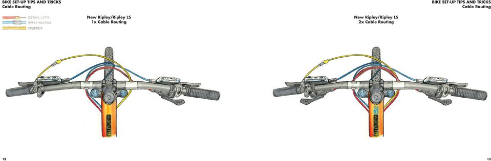
8 BIKE SET-UP TIPS AND TRICKS Cable Routing BIKE SET-UP TIPS AND TRICKS Cable Routing New Ripley/Ripley LS 1x Cable Routing New Ripley/Ripley LS 2x Cable Routing 12 13
9 BIKE SET-UP TIPS AND TRICKS Cable Routing BIKE SET-UP TIPS AND TRICKS Mojo HD3 Routing A Note on Routing with Top Pull Derailleurs We have made the Mojo HD3 and the New Ripley compatible with the new Shimano side swing front derailleurs. Should you be retrofitting an older style top pull derailleur to either one of these frames, it is possible and here s the recommended routing (Ripley shown, HD3 would be done similarly). Cable Routing Ports The illustration below shows the various ports we have available for the New Ripley, HD3 and Tranny29. A Note for UK/AU/NZ/ZA Folk and Some Motorcycle Riders Your brake levers are most likely set up opposite to the rest of the world i.e. front brake on the right-hand side of the handlebars, and rear brake on the left-hand side. For you folks, we recommend you route the rear brake line directly from the lever on the left-hand side of the handlebar to the left side of the down tube, attaching it using existing guides. The line will have a slightly tighter radius than it would otherwise but that is OK. Be sure to leave sufficient line so the handlebars can rotate in the event of a crash. If necessary, use clear adhesive dots to prevent the line rubbing on the headtube. Depending on the configuration of your bike, a second more complicated option may be possible if you re not using either a front derailleur or internally routed dropper post. Route the rear brake line inside the down tube. The line enters the frame at the port on the top right of the down tube, and exits at the port on the lower left. Walk this DIY path alone, and be prepared to bleed your brakes after the cables are routed. You will also need to use our hydro line port

10 BIKE SET-UP TIPS AND TRICKS BIKE SET-UP TIPS AND TRICKS The Mojo HD3 uses our new versatile cable port system for cable routing. We have several port styles available, depending on your drivetrain and dropper configuration. Mojo HD3 Driveside Cable Routing Mojo HD3 Non-Driveside Cable Routing The most common setup these days is a 1X drivetrain with an internally mounted dropper. We spec the KS LEV Integra. We generally recommend you run your brake on the exterior, along the left side of the down tube

11 BIKE SET-UP TIPS AND TRICKS BIKE SET-UP TIPS AND TRICKS A Note HD3 Routing with Top Pull Derailleurs We have made the Mojo HD3 compatible with the new Shimano side swing front derailleurs. Should you be retrofitting an older style top pull derailleur refer to new Ripley Routing on page 14. Mojo HD3 Derailleur Cable Routing Mojo HD3 Dropper Cable Routing A Note on Reverb Dropper Routing The Reverb dropper routing we prefer is not illustrated, but we ll describe it for you. You need three of our hydro cable stops. Route the Reverb into the left side of the down tube (it s a single port) using our hydro port. Use two other hydro ports at the bottom left side of the down tube and seattube, and fish the dropper tubing through to the seattube. Connect as normal. If you re using Shimano s new side pull front derailleur, route it through the drive side of the down tube and then out at the bottom of the drive side. For top mount front derailleurs use the toptube for entry and exit for the derailleur cable. Note that you have the choice of full housing or interrupted derailleur housing with our versatile port configurations. For droppers that use cable and housing, such as the KS LEV, route the housing according to the illustrations
 using our hydro port.")
12 BIKE SET-UP TIPS AND TRICKS BIKE SET-UP TIPS AND TRICKS Mojo HD3 Brake Cable Routing Mojo HD3 1x Cable Routing 2X routing on the HD3 is the same as the Tranny29 as shown on page

13 BIKE SET-UP TIPS AND TRICKS BIKE SET-UP TIPS AND TRICKS With the Tranny29, we pioneered our cable port system that you also see on the HD3. The routing is also fairly straight forward, with one twist. We like to route the rear derailleur housing before the two halves of the frame are assembled (and before you install your BB!). Tranny29 Driveside Cable Routing Tranny29 Non-Driveside Cable Routing Since we ship the frames with both halves assembled, the person building the bike will have to remove the slot machine hardware, separate the frame halves and start threading housing from the front of the bike, through the slot machine, and into the drive-side chainstay

14 BIKE SET-UP TIPS AND TRICKS Tranny29 Cable Routing BIKE SET-UP TIPS AND TRICKS Tranny29 Cable Routing Tranny29 Single Speed Cable Routing Tranny29 2x Cable Routing 24 25

15 BIKE SET-UP TIPS AND TRICKS Tranny29 Gearing BIKE SET-UP TIPS AND TRICKS Chain Rings The Tranny29 can be setup 1X, 2X, 3X (remember that?) or as a single speed. A direct mount front derailleur mount is provided for multiple ring setups. Single Speed Set-up The Tranny29 features an adjustable length chainstay with a seatstay attachment that splits apart, allowing you to feed a belt into the rear triangle. We offer the Gates Carbon drive on our Tranny Unchained version. The Gates belt needs no maintenance, and is incredibly silent in its operation. Adjusting the tension of the belt is easy, particularly if you have a helper. Here is one way we ve found works well: Once you have the Tranny29 completely assembled and the belt is in place, loosen both the slot machine bolt behind the bottom bracket (accessible from the non drive side) and the seat stay attachment bolt. Using a helper, sit on the saddle with all of your weight and bounce up and down a few times. Settle onto the saddle (feet dangling is best so 100% of your weight is on the saddle), and have your helper tighten the slot machine bolt to 25 Nm. Next tighten the seat stay bolts to 10 Nm. If you don t have a helper, stand on the right side of your bike and lean over your bike with your stomach on your saddle. Put as much weight as you can on your saddle while tightening the slot machine bolt. Note that Gates publishes a much higher torque setting than what you will achieve with our method. We have found that the added stiffness of the Tranny29 rear triangle allows you to get away with lower belt tension. Troubleshooting If the slot machine slips or creaks on hard acceleration or high torque application, you can raise the slot machine torque to 30 Nm. Your Tranny29 comes with an application of Carbon Assembly paste applied to the internal faces of the slot machine. If you are having trouble with the slot machine holding, a re-application of the assembly paste should be tried. Be sure there is Ti anti-seize on the slot machine nut on the drive side. It is applied during assembly of your Tranny29 so you shouldn t need to. Mojo HD3 The HD3 framesets ship with a removable direct mount front derailleur mount and a cover which mounts on the back of the seattube if you re not running a front derailleur. We manufacture a removable ISCG 05 mount which mounts on the splines on the drive side of the bottom bracket. Standard procedures apply to mounting an ISCG 05 compatible chainguide or bash on the HD3. The HD3 is also compatible with all common direct mount front derailleurs in both 2X and 3X configurations. If you need an ISCG 05 adapter, a derailleur cover or a derailleur mount, they re available in our online store:

16 BIKE SET-UP TIPS AND TRICKS BIKE SET-UP TIPS AND TRICKS Chain Length To determine the correct chain length: shift into the large chainring and largest cog and let all the air out of your shock (on suspension bikes only, duh). Thread the chain through the gears and derailleurs, compress the suspension all the way to bottom out, and cut the chain at the minimum length needed with the rear derailleur stretched out. Tapered Headtube The HD3, Ripleys, Tranny29 and Hakkalugi all feature a tapered headtube that work with tapered steerer forks. The headset on the HD3 is a ZS44/ZS56. This standard is compatible with both the Chris King InSet 2 and certain Cane Creek headsets (see our webstore for the offerings). Headsets on the Ripleys and Tranny29 are the ZS44/EC49. This standard is compatible with both the Chris King InSet 3 and certain Cane Creek headsets. The Hakkalügi uses an IS41/IS52. To learn more about these various headset standards, visit: Rear Dropouts and Disc Brake Mounts The one piece disc brake boss/non drive side dropout on the HD3, Ripleys, and Tranny29 is molded carbon. Depending on the model the rear axle is either a Maxle or a Shimano through axle. The Shimano axle uses a 5mm hex wrench and the Maxle is similar to the common through axle front forks. Our mountain bikes are designed to bolt a post mount standard caliper directly to the frame for a 160mm rotor or to a 180mm or 185mm rotor with a post to post style adapter (The Hakkalügi disc is a 140mm post mount and the axle is a 135mm quick release style). Bottlecage The Ripley works best with a side loading cage, we like the Arundel side loader. There are two sets of holes in the cage, use the ones that position it away from the seattube. When using any other cage, let the air out of your shock to check clearance between the swingarm and bottle. There are two heavy duty Riv Nut inserts on the underside of the down tube of many of our bikes, to allow the mounting of a bottle cage. We ve put them there primarily for a spare water bottle, a tool kit or for a battery if you re night riding. Do not put a large bottle under the down tube of a small Ripley, the front tire will hit it at bottom out. Please do not attempt to retrieve a water bottle from this cage location during riding! There are extra long socket head screws provided for your use in these holes. They are longer than your average screw. We suggest using a heavy duty cage for holding batteries since the lighter weight cages don t seem to hold up to this sort of abuse. Hakkalügi Disc Brake Set-Up If using mechanical discs and drop bar levers, don t forget to put an in-line cable adjuster, as drop levers don t have adjusters built in. You can utilize the split cable spacers that come with the frame on the toptube triple stops for either disc (hydraulic hose) or cable housing. General Frame Information Care for Carbon The carbon fiber monocoque frame is extremely strong, and should provide years of trouble free use, provided you care for it properly and don t overly huck every 50 foot gap you see. Keep your bike clean and inspect it often. Although each and every bike gets tested at the factory for strength, it never hurts to look at the areas where the tubes join, where the shocks and dropouts mount and any other areas that may receive stress during usage. Check for loose bearings, headsets, shocks and forks and such. Visually inspect the bike before each ride and also during each cleaning. Carbon Assembly Compound This stuff is grease, but with a bunch of tiny plastic beads added. This increases friction between components, great for holding your carbon seat post or handlebars in place without excessive clamping force. While grease won t hurt any of our seattubes, carbon assembly paste works even better. Do not use the carbon assembly compound when installing the headset, bottom bracket, shock, water bottle cage, or anything that has bearings. Paint and Decals There is a protective clear coat applied over the final carbon layer on all of our frames. You can repair small chips and scratches with clear nail polish (not supplied.) Colored frames are painted with a high quality polyurethane enamel. Both of these finishes can wear through with repeated rubbing of cables or chain slap. Using adhesive vinyl protectors to guard against cable rub and chain slap can help limit wear and tear on your frame. Should you need to touch up areas of the frame where the paint has been compromised, we recommend either a hobby shop, myperfectcolor.com or testors.com for a good source of enamel touch up paint. We try to make our frame finishes as durable as possible, but it is impossible to test in all conditions and against all chemicals. Be aware that use of certain cleaners, lubricants, or foodstuffs, including Simple Green and Pedro s Bike Lust, may damage the paint. Please note that paint damage is not covered under the warranty. Clean any of our frames with mild soap and water only. The Ripley and HD3 decals have a clear coat applied over the decals. The Tranny29 and Hakkalügi decals are top mount. Be aware that pressure washing may damage the decals on these bikes

17 FORK SETUP FORK SETUP Fork Setup Information Read this first for a general understanding of fork set-up or skip straight to the air pressure charts (page 34) if you just want to go ride. Important Note About Ripley Forks: For the best possible performance, be sure you are using a 51mm offset fork on the Ripley. All the Ripley forks we supply have 51mm offsets, so if you (or your retailer) got the fork from Ibis, it s got the right offset. Positive Pressure This is the main air spring that supports your weight. Adjust the air pressure so that you come close to using all the travel on a typical ride. Usually you can mimic your maximum impacts by grabbing the front brake and pushing down HARD on the bars. If you are getting 80 90% of the fork s travel doing this, your positive air spring is in the right range. Actual riding will often push the fork a little further than this test. Low Speed Compression Damping Low speed compression damping is used to reduce unwanted movement and over travel due to low speed changes like out of the saddle pedaling and subtle variations in the trail that can cause wallowing etc. Adjust to your preference. Lockout As the name implies this turns the fork rigid (or close to it) for out of the saddle efforts or riding on the road. Most forks have a blowoff so that the fork will move if a large enough impact is felt. The threshold or blowoff when the lockout lets the fork start to move is often adjustable. It s called Gate in Rock Shox parlance and Blowoff Threshold in Fox s language. Usually the goal is to have the lockout at the minimum setting needed to stop the fork movement while pedaling out of the saddle, but allowing it to still move fairly easily when an impact is felt. High Speed Compression Damping If your fork has a high speed compression damping control, this would usually be used to slow things down during big hits to avoid bottoming. It would usually be set at the lowest level needed to avoid bottoming out. Rebound Adjust the rebound so that the front end does not bounce off the ground after a drop off or large bump. If adjusted too slow, the fork may pack down and feel sluggish. In order to conserve momentum and remain compliant the suspension needs to recover fairly quickly and push off the back side of bumps and holes. If the rebound is adjusted too slow, rolling energy is lost to damping and vibration. If it is adjusted too fast the bike will bounce after bumps and drops. Adjust to your preference. Fox 36 Rebound The rebound adjustment is dependent on the air pressure setting. For example, higher air pressures require lower rebound settings. Use your air pressure to find your rebound setting. Turn your rebound knob to the closed position (full clockwise) until it stops. Then back it out (counter-clockwise) to the number of clicks shown in the table on the next page. Fox 34 For 2016, we are supplying the all new Fox 34 fork with 130mm of travel on the Ripley. Compared to last year s 34, it shed almost 300 grams. That means it weighs roughly the same as last year s long-travel 32, and has gobs of added stiffness, necessary for a 120mm travel 29er. There s a new air spring assembly and new FIT4 damper cartridge. Performance-wise it feels like the 36, which is a great thing. We like this fork a lot. Fox Float 36 RockShox firmly kicked Fox in the youknow-what s when they came out with the Pike. Fox needed to respond, and they came back swinging with the new 36. The 36 does everything better than the prior incarnations, it s lighter, incredibly smooth and supple right out of the box (prior versions needed to be broken in), stiffer and it makes your coffee for you in the morning. OK we might be exaggerating that last bit Fox RC2 Base Settings Use this diagram as a starting point for your compression and rebound adjusters. Turn your adjusters all the way in (full clockwise) until they stop. Then back them out (counter-clockwise) to the number of clicks shown below. but not the rest. For those wanting just a little more robustness up front, or simply more partial to Fox, the 160mm travel 36 with the RC2 damper will deliver. Special Blend Special Blend bikes come with SLX drivetrains and X-Fusion suspension. X-Fusion RL2 Forks X-Fusion RL2 trail forks offer an efficient and high quality damping system in a simple OPEN 22 CLICKS OPEN 26 CLICKS OPEN 18 CLICKS 18 CLICKS OUT HSC (HIGH-SPEED COMPRESSION) 13 CLICKS OUT LSC (LOW-SPEED COMPRESSION) CLICKS OUT REBOUND package. The RL2 sealed cartridge damper systems offer external rebound and lockout adjustment. The Mojo HD3 Special Blend features the 34mm chassis Sweep RL2 with 160mm of travel and the Ripley Special Blend features the 34mm chassis Trace RL2 with 120mm of travel. Pressure charts can be found on page 35. CLOSED (FULL CLOCKWISE) CLOSED (FULL CLOCKWISE) CLOSED (FULL CLOCKWISE)

18 FORK SETUP Setting Sag FORK SETUP Setting Sag Step 1 Add recommended air for rider weight (see charts on following pages). With bike on level ground, bounce up and down a bit to overcome shock stiction. Settle into your riding position. Step 2 Slide o-ring until it rests on wiper, then dismount without disturbing o-ring's position. Step 3 Measure sag the distance from o-ring to wiper. Start with sag of 15 20% of travel and adjust to your preference

19 FORK SETUP Starting Pressures for Setting Sag FORK SETUP Starting Pressures for Setting Sag RockShox Pike 650b RockShox Pike 29 X-Fusion Sweep 650b X-Fusion Trace 29 X-Fusion Slide 29 RIDER WEIGHT mm 160mm RIDER WEIGHT mm RIDER WEIGHT 160mm RIDER WEIGHT 120mm RIDER WEIGHT 100mm lb kg psi psi lb kg psi lb kg psi bar lb kg psi bar lb kg psi bar Max Max Fox Float b RIDER WEIGHT 160mm lb kg psi Fox Float (with130mm Travel) RIDER WEIGHT FLOAT lb kg psi Max 125 Do not exceed maximum air pressures Max 120 Ibis Handy Sag Measurer in Milimeters 34 35

20 REAR SHOCK SETUP REAR SHOCK SETUP Ripley Sag We recommend starting with air pressure in the shock equal to 10% over your riding weight in pounds. Shoot for.45 (~11mm) of sag on the shock. Less pressure gives a slacker seat angle and overall smoother ride. More pressure gives a firmer suspension feel and steeper seat angle and more over the pedals riding position. Mojo HD3 Sag We recommend starting with air pressure in the shock equal to your riding weight in pounds. Shoot for.55 (~14mm) of sag. Check the Sag With the shock in open mode (or ProPedal turned off for earlier shocks), sit on your bike in a normal riding position. Reach down and slide the o ring up the shock shaft against the wiper seal. Next, gently step off of the bike taking care not to further compress the suspension. For the Ripley, the distance from the o ring to the wiper seal should be about 11mm. On the Mojo HD3, sag should be about 14mm for XC and 17 19mm for gravity rides. Experiment and see what works best for your trails and riding style. Trail Adjust The 2016 Float DPS is a big giant improvement for both Ripleys and the HD3. The shock has totally new internals. There is a wider range of compression adjustment when you change positions using the blue lever. The shock has the new EVOL air sleeve that gives both better small bump compliance AND more support though the mid stroke. It also gives increased bottoming resistance. There s a 3 position on-the-fly (lever) adjustment like before. They control low speed compression damping. They re called Open-Medium-Firm (compared to last year s Climb, Trail, Descend). The Open mode is the tunable one (instead of the middle mode being tunable like last year). That enables you to adjust the mode that you use most often, then have the preset Medium and Firm modes if you want to firm things up for fire road climbing or pavement (we rarely use these settings on our bikes). Adjusting Rebound The Float DPS has adjustable rebound damping. It s adjusted by turning the red dial on the inside of the lever. Generally you want it as fast as you can set it without getting bounced off the saddle after a bump or drop (like riding off a curb in the saddle.) If the rebound setting is too slow the shock will be partially compressed when you hit the next bump resulting in packing down. Too fast and the bike will bounce you up in the air after bumps and drops. Adjust to your preference. The Ripley and the HD3 use the following shock and shock hardware: Upper Hardware: 21.8mm wide with an 8mm bore Lower Hardware: Bushing removed, use provided clevis bolt Ripley Shock 7.25 (184mm) eye to eye 1.75 (44mm) shaft travel HD3 Shock: (200mm) eye to eye 2.25 (57mm) shaft travel Setting Air Pressure for the First Time with the EVOL Sleeve It is critically important to add or remove air from the EVOL sleeve as detailed below to experience the best possible performance. IMPORTANT NOTE: When adding air to the air chamber, it is crucial to equalize the positive and negative air chambers by slowly compressing the shock through 25% of its travel times after every 50psi addition. Adding air to the shock without periodically equalizing the air chambers can lead to a condition in which the shock has more pressure in the positive chamber than the negative. In this condition the shock will be very stiff and can top-out. You can equalize the air chambers by slowly compressing the shock until you feel and hear a transfer of air. Hold the shock at this point for a few seconds to allow the air to transfer from the positive to the negative chamber. When releasing air from the air chamber, it is important to do this slowly so the shock can transfer air from the negative to positive chamber and then be released through the Schrader valve. Releasing the air pressure too quickly can induce a condition in which the negative chamber has more pressure than the positive chamber. In this condition the shock will compress into its travel and not fully extend. You can remedy this by adding air pressure until the shock extends, then slowly compressing the shock through 25% of its travel times. For a more detailed explanation, go to: ridefox.com\help.php?m=bike&id=555# usingtheevolairsleeve Here s an excellent review of the Fox DPS with EVOL sleeve by Pinkbike: pinkbike.com/news/fox-float-dps-shockreview.html X-Fusion Microlite RL The X-Fusion Microlite RL (optional on the Ripley) has a reduced body and air canister size making it one of the lightest performance shocks on the market. The reduced surface area provides a very active and supple ride quality while the smaller air canister gives you a progressive spring curve. With adjustable rebound and lockout adjustment this shock compliments the Ripley s own capabilities well
, sit on your bike in a normal riding position.")
21 REAR SHOCK SETUP REAR SHOCK SETUP Updating the Original Ripley Suspension If you wish to update your first generation Ripley to the excellent new Float DPS and Float 34, here are the part numbers you will need to order. Note, we are not allowed to sell Fox suspension other than bolted onto a bike. Fork Part No: Description: 2016, 34, K, FLOAT, 29in, F-S, 130, 3Pos-Adj, FIT4, Matte Blk, Orange Logo, 15QRx100, 1.5 T, 51mm Rake, AM Shock Part No: Description: 2016, FLOAT DPS, F-S, K, 3pos-Adj SV, FOX, AM, 7.250, 1.750, CM, RM, Climb F The Ripley Float DPS shock spec is quite different from Fox s aftermarket offering in that size. So, you d need to buy the shock listed on the line above Then buy an EVOL air sleeve separately and have the shock revalved to light compression damping. It s possible but adds rework cost on top of purchasing the shock itself. Again, we re not allowed to sell you the shock by itself. If you really want to Harness the Gnarness of the Mojo HD3 The DPS shock with EVOL sleeve which is standard on the HD3 works extremely well for most riders. We have worked closely with Fox to develop custom tunes for the HD3 and Ripley. Some people want to go bigger, so we have some options: Cane Creek DBinline Riders who need a more aggressive or adjustable shock can instead order a Cane Creek DBinline for the HD3 or the Ripley. The DBinline provides an extremely wide range of tuning options, with individually adjustable low-speed compression, high-speed compression, low-speed rebound and high-speed rebound. We have worked extensively with Cane Creek on these shocks, and have developed base tunes as a starting point to get your own bike dialed. The base tunes for DBinlines on the Ripleys and HD3 can be found on page 41. Fox Float X2 Fox fires yet another across the bow with the new for 2016 Float X2. If you ride aggressively and like a shock with a lot of tuning options, the X2 is a good choice for you. Recommended Settings Use your air spring pressure in the table on the right to find the suggested starting Rod Valve System (RVS) damper settings for your shock. Turn all four damper adjusters to the closed position (full clockwise) until they stop. Then back them out (counterclockwise) to the number of clicks shown in the table on the right. Custom Tuning If none of these shocks suit your fancy, you can venture out on you own into the world of custom shock procurement. The HD3 rides best with a low compression/ medium rebound tune and very progressive spring rate. *COUNT CLICKS FROM CLOSED: 0 CLICKS = CLOSED* AIR SPRING PRESSURE RECOMMENDED LSR SETTING RECOMMENDED HSR SETTING RECOMMENDED LSC SETTING RECOMMENDED HSC SETTING 90 Open Open Open Open Open 22-Open
22 REAR SHOCK SETUP REAR SHOCK SETUP New Ripley/Ripley LS DBinline Base Tune RECOMMENDED SAG 13mm HD3 DBinline Base Tune RECOMMENDED SAG 18mm HSC PLUSH 0.5 HSC [HIGH SPEED COMPRESSION] 0 TURNS TURNS 4 ABSORBS IMPACT HSC PLUSH 0.5 HSC [HIGH SPEED COMPRESSION] 0 TURNS TURNS 4 ABSORBS IMPACT LSC SUPPLE 4 LSC [LOW SPEED COMPRESSION] 0 CLICKS CLICKS 25 PEDAL EFFICIENCY LSC SUPPLE 4 LSC [LOW SPEED COMPRESSION] 0 CLICKS CLICKS 25 PEDAL EFFICIENCY HSR LIVELY POP HSR [HIGH SPEED REBOUND] 0 TURNS TURNS 4 3 G-OUT CONTROL HSR LIVELY POP HSR [HIGH SPEED REBOUND] 0 TURNS TURNS 4 3 G-OUT CONTROL LSR LSR [LOW SPEED REBOUND] 10 LSR LSR [LOW SPEED REBOUND] 8 PLUSH 0 CLICKS CLICKS 25 FIRM PLUSH 0 CLICKS CLICKS 25 FIRM 40 41
23 REAR SHOCK SETUP Starting Pressures for Setting Sag Cane Creek DBinline (New Ripleys) 25% Sag 30% Sag RIDER WEIGHT PRESSURE RIDER WEIGHT PRESSURE Cane Creek DBinline (HD3) 25% Sag 30% Sag RIDER WEIGHT PRESSURE RIDER WEIGHT PRESSURE X-Fusion Microlite RL (New Ripleys) 30% Sag 35% Sag RIDER WEIGHT PRESSURE RIDER WEIGHT PRESSURE
24 MAINTENANCE MAINTENANCE Working on Ripley This information is shown in a video: Should you find it necessary to replace any of the bearings on the Ripley eccentric linkages, you will need to remove the swingarm. For that, you will need the following tools: 12mm open end wrench 2 x 6mm Allen wrench 1 x 5mm Allen wrench 2 x 4mm Allen wrenches Bearing Replacement Please refer to the section on Ripley Swingarm Removal on pages Complete instructions can be found on this video: or on our website at com/support/technical_articles/ripley_ bearing_replacement/ Ripley Bearing Specs Eccentric Core Inner Bearings: RS (30 x 42 x 7) These are the same as BB30 bearings. Lower Outer Bearings: 608-RS 8x22x7 These mount in the swingarm and can be found in skate shops. Upper Outerbearing: 698-RS 8x19x6 These mount in the swingarm and can be found in skate shops. Working on Mojo HD3 The linkage assemblies on the HD3 are designed to be removed and replaced easily. Be sure to purchase a fresh link set before removing the old ones to skip any downtime. There are no bearings to press out, nor any axles to hammer. Upper and lower pivot assemblies are available in the buy section of our website, or you can have your dealer order them from Ibis for you. Replacement is super simple and requires these common tools: 2x 4mm Allen wrenches 2x 6mm Allen wrenches 2x 5mm Allen wrenches Loctite 243 (or 242) blue thread locker Replacing Linkages Please refer to the section on Mojo HD3 Swingarm Removal in this manual on pages Bearing Replacement If you re handy with a bench vice and have a good supply of sockets, you can attempt the replacement of the bearings in the upper and lower link yourself. While we don t have step by step instructions, you are welcome to purchase the bearings and try it yourself. Mojo HD3 Bearing Specs The lower links use DDR1526 bearings on the drive side and 6902rs on the non-drive side. The upper links are 6800rs all around. Bearing Kits Enduro Bearing kits are available for all modern Ibis suspension bikes at
25 FRAME HARDWARE New Ripley/Ripley LS FRAME HARDWARE Mojo HD3 single stop single stop single stop eccentric cap double port/stop m4x8 flat head bolt double port/stop eccentric cap bolt upper eccentric shaft bolt lower shock bolt lower shock nut clevis clevis reducer clevis bushing clevis bushing o-ring outer eccentric bearing upper shock pin shock washer m5x8 socket head screw double port/stop clevis outer reducer clevis mounting bolt clevis bushing clevis inner reducer clevis clevis shock bolt clevis shock nut single stop single port rock guard clevis pivot nut clevis pivot bolt single stop single stop lower eccentric shaft lower swingarm bearing upper swingarm bearing single stop upper eccentric spacer outer eccentric bearing upper eccentric core upper eccentric shaft lower eccentric core lower eccentric shaft bolt lower eccentric spacer front derailleur mount w/2 m5x10 flat head bolts single stop front derailleur mount cover for single ring drive train single stop iscg mount bolt-on cable guide double stop upper link w/bearings upper link bolt lower link w/bearings derailleur hanger derailleur hanger bolt seatstay guard lower link shaft bolts hd3 lower link shaft hdr lower link shaft chainsuck plate derailleur hanger chain suck stainless steel plate chainstay guard chain stay rubber guard 46 47
26 FRAME HARDWARE Tranny29 FRAME HARDWARE single cable port w/m4 x 8 flat head bolt single cable stop w/m4 x 8 flat head bolt single cable port w/m4 x 8 flat head bolt seatstay yolk nut single cable stop seatstay yolk bolt seatstay cable port derailleur hanger derailleur hanger mounting nut slot machine seal slot machine bolt slot machine steel washer slot machine alloy washer derailleur hanger mounting bolt chainsuck plate slot machine nut 48 49
27 FRAME HARDWARE Torque Specs Ripley HARDWARE TORQUE SPEC. THREAD TREATMENT Clevis to Swingarm Bolts 5 Nm Loctite 243 Eccentric Shaft Bolts 8 Nm Lower Shock to Clevis Bolts 8 Nm Loctite 243 Upper and Lower Eccentric Core Bolts 8 Nm Loctite 243 Upper Shock Mount Bolts 4 Nm Ti anti-seize Titanium Bolts: use Ti anti-seize on the shaft and Loctite 243 on the threads Aluminum Bolts: use grease on the shaft and Loctite 243 on the threads Hexle Rear Axle: There is not a numerical torque figure for the Hexle. We recommend tightening the 5mm with your multi tool that you carry with you. This way you ll be able to remove it in case of a flat out on a ride. Tranny29 HARDWARE TORQUE SPEC. THREAD TREATMENT Cable Port 2 Nm Grease Seat Stay Bolts 10 Nm Ti anti-seize Slot Machine Bolt (Geared Riding) 25-30Nm Ti anti-seize Slot Machine Bolt (Single Speed Riding) 25-30Nm Ti anti-seize All Models HARDWARE TORQUE SPEC. THREAD TREATMENT Derailleur Hanger Bolt 5 Nm Grease HD3 HARDWARE TORQUE SPEC. THREAD TREATMENT Cable Port 2 Nm Grease Clevis to Seatstay 15 Nm Loctite 243 Front Derailleur Cover Mount 5 Nm Loctite 243 Front Derailleur Mount 5 Nm Loctite 243 Lower Links 15 Nm Loctite 243 Lower Shock to Clevis Bolts 15 Nm Loctite 243 Rear Brake Caliper 6 Nm Loctite 243 Seat Binder 5 Nm Ti anti-seize Upper Link Bolts 10 Nm Loctite 243 Upper Shock Mount Bolts 4 Nm Ti anti-seize 50 51
28 RIPLEY SWINGARM REMOVAL RIPLEY SWINGARM REMOVAL This information is shown in a video: Step 1 Step 2 Step 3 Step 4 Put your Ripley in a work stand. Remove the front derailleur, cranks, brakes and the rear wheel. Remove the upper 4mm shock bolts and lower 5mm clevis bolts (Do not use Y or T tools when removing the clevis bolts). Gently remove the clevis from the swingarm, leaving the shock attached. Remove both of the eccentric core bolts using 6mm allen wrenches. Remove the countersunk bolt from each eccentric core cap. You might need to use a 12mm open end wrench to prevent the eccentric from rotating. Do not use a crescent wrench, cave man! Gently remove the cap, and then you will be able to push the eccentric core out of the frame
29 RIPLEY SWINGARM REMOVAL RIPLEY SWINGARM REMOVAL This information is shown in a video: Note: Special tools are needed to remove and replace the Ripley bearings in the seattube and in the swingarm. Please do not attempt to remove and replace these bearings without the tool. Instructions on removal and re-installation of the bearings using the Ibis Clemens Tool (drawing to the right) can be found in the video above and on the Ibis website under Support>Technical Articles>Ripley Bearing Replacement. You can purchase the tool at our online store: com/clemens-bearing-tool-for-ripley-p195. aspx To reinstall the swingarm, work in the reverse order. If you are replacing the eccentric bearings, be sure to clean the bearing surfaces in the frame and the bearings themselves, making sure the press surfaces are free of any contamination such as grease or oil. Apply a thin layer of Loctite 680 retaining compound and use the Clemens tool to press in the bearings. Let the bearing retainer dry overnight before riding the bike again. Add grease to the core when reinstalling, and a lightly grease the inner lip of the eccentric cap. Don t forget the two spacers that go between the BB30 bearings in the seattube. The chamfered hole on the cap aligns with the threaded hole on the eccentric core. Use blue loctite on the bolt. Use a 12mm open end wrench to align the eccentrics so that the flats are horizontal and at the 9 o clock position when the frame is parallel with the ground. Gently slide the swingarm onto the eccentrics. Insert the swingarm bolts, lower bolt from the non drive side, upper from the drive side. The conehead nut goes on the lower bolt, on the drive side. Ride it and weep (with joy)
30 MOJO HD3 SWINGARM REMOVAL MOJO SWINGARM REMOVAL Step 1 Step 2 Step 3 Step 4 Step 5 Step 6 Put your freshly cleaned Mojo in a work stand. Remove the front derailleur, cranks, and the rear wheel. Remove the shock and clevis assembly by removing the upper shock mount bolt and shaft with two 4mm Allen wrenches. Next, remove the clevis to swingarm bolts with a 5mm Allen. Carefully separate the shock and clevis assembly from the frame. Remove the lower shock mount bolt with two 6mm Allens. Remove front lower link shaft and the two forward upper link bolts. Pull the swingarm with the linkages still attached away from the front triangle. Remove the axle in the lower link that passes through the swingarm and separate the link from the swingarm. Also remove the upper link from the swingarm. * To reassemble your bike, follow the steps in reverse order. Remember to use a little Loctite blue thread locker (we prefer Loctite 243) on all steel and aluminum fasteners, and to use anti seize on all titanium fasteners. Refer to the torque chart on page
31 WARRANTY DOCUMENTATION Warranty Ibis Cycles warrants Ibis frames to be free from defects in materials and workmanship for a period of 3 years from date of sale. This limited warranty applies to the original owner and is nontransferable. Ibis will, at its sole discretion, repair or replace any frame or frame component that it determines to be defective. This warranty does not cover normal wear and tear, nor does it apply to damage that is the result of abuse, neglect, improper assembly, improper maintenance, alteration, misuse or massive hucking. The costs of disassembly, reassembly or repair of any attached components are not covered by this warranty and are the responsibility of the original owner. Under no circumstance are the costs of shipping to or from Ibis covered by this limited warranty. This warranty applies exclusively to Ibis bicycles manufactured after July 1, No Fault Replacement Should your Ibis be involved in a crash or other non warranty situation, Ibis Cycles will make replacement parts available at a minimum charge to the original owner. Ibis Cycles does this at its sole discretion and reserves the right to refuse this offer, so don t go crashing your bike. Unless otherwise provided, the sole remedy under the above warranty, or any implied warranty, is limited to the replacement of defective parts with those of equal or greater value at the sole discretion of Ibis Cycles. In no event shall Ibis Cycles be held responsible for direct, incidental or consequential damages, including, without limitation, damages for personal injury, property damage, or economic losses, whether based on contract, warranty, negligence, product liability, or any other theory. Warranty Registration Don t forget to register your warranty online at: warranty/warranty_registration/ The Fox forks and shocks we use on our bikes are warrantied for one year. For USA Warranty Service: (800) FOX-SHOX / service@foxracingshox.com For International Warranty Service: Contact a Fox service center: fox_tech_center/service.htm Parts Find these online at the buy portion our website or get them directly from your Ibis dealer. Contact us or your dealer for more info. We recommend you always ride with one or two spare derailleur hangers. Serial Number We recommend you write down your serial number for future reference. The serial number is located under the bottom bracket. Note that if you have a Mojo HD3 with a cable guard installed, you will need to remove the cable gaurd to obtain the serial number. We want you to register the serial numbers on the front triangle, not the swingarm. Rider Info. Name Address Tel. No. Fork Settings PSI Clicks Rebound Clicks Compression Specifications and construction details given are not binding. Bike Info. Model Paint Color Ft. Triangle Serial Number Swingarm Serial Number Shock Settings PSI Clicks Rebound Clicks Compression We reserve the right to carry out modifications without prior notice. Nearest Ibis Dealer Name Address Service Manager Tel. No. First Ride on the New Rig: Route Crew Verdict RIDE MORE, WORK LESS
32 CHUCK S RECIPE Impress your Riding Buddies with Chuck s Homemade Energy Bars Ingredients 1/2 cup salted almonds 1/2 cup roasted sunflower seeds, or other chopped nuts 2 cups raisins, or other chopped dried fruit 2 cups rolled or instant oats 2 cups toasted rice cereal, such as Rice Krispies 1/4 cup toasted wheat germ, (optional) 1/2 cup creamy or crunchy natural almond butter 1/2 cup packed brown sugar 1/2 cup honey (or agave sweetener) 1 teaspoon vanilla extract Preparation 1. Coat a 9 by 13 inch baking pan with cooking spray. 2. Combine the almonds, sunflower seeds (or other nuts), raisins (or other dried fruit), oats, rice cereal and wheat germ (if using) in a large bowl. 3. Combine almond butter, brown sugar and corn syrup (or honey) in a large microwaveable bowl; microwave on High until bubbling, 1 to 2 minutes. Add vanilla and stir until blended. Pour the almond butter mixture over the dry ingredients and stir until coated. 4. Transfer the mixture to the prepared pan. Press down firmly. (It helps to coat your fingers with cooking spray.) Let stand for about 1 hour to harden. Cut into bars. Tips & Notes Make Ahead Tip: Individually wrap and keep at room temperature for up to 1 week or freeze for up to 1 month. Thaw at room temperature. Makes 16 Bars, better than Method Man in his prime. Nutrition Per serving: 255 calories; 9g fat (1g sat., 2g mono); 0 mg cholesterol; 42g carbohydrates; 5g protein; 3g fiber; 95mg sodium; 242mg potassium. Contact Information Toll Free (formerly called an 800 number but all 800 s are used up we guess) (1 866 IBIS 635) Not Toll Free (unless maybe you re at work) (Or if you re all fancy and internationally savvy: ) Electronic Mail (sometimes referred to as ) askchuck@ibiscycles.com Fax (remember those?) Really Old Fashioned Snail Mail 2240 Delaware Ave. Santa Cruz, CA ibiscycles.com 60 61
33 ALPHABETICAL INDEX Video Index Airstream Bearing Specs, Mojo Bearing Specs, Ripley Being kicked in the you know whats Bottle Cage Cable Routing Cannoli Chuck s Recipe Das Liberator DBinline Base Tune Fork Setup Fox Float Air Pressure Fox RC2 Base Settings Frame Care Frame Hardware Drawings Frame Hardware Torque Spec Chart Geometry Hand Job Hakkalügi Disc Brake Set-Up Harness the Gnarness Introduction ISCG 05 Method Man Peanut Butter Wrench Rear Shock Air Pressure Chart Rear Shock Tuning Rebounding from a bad relationship Ride and weep with joy Serial Number Slot Machine Snail Mail Stack and Reach Swingarm Removal Warranty Ripley: Replacing the Eccentric Link Bearings 52 Ripley: Swingarm Removal 54 Ripley: Bearing Tool
34 NOTES 64 65
35 66
36 ibiscycles.com
INSTRUCTION BOOK. Notes on Tuning and Maintenance of Ibis Bicycles, Rev. E
 INSTRUCTION BOOK Notes on Tuning and Maintenance of Ibis Bicycles, Rev. E Instruction Manual Notes on Tuning and Maintenance of Ibis Bicycles, Rev. E Reprinting Permitted if Source Quoted Introduction
For exploded diagram and part number information, refer to the Spare Parts Catalog available on our website at www.rockshox.com.
 For exploded diagram and part number information, refer to the Spare Parts Catalog available on our website at www.rockshox.com. 2 0 0 5 D U K E A I R X C / S L / R A C E S E R V I C E G U I D E Information
VT SERIES. Owners Manual VARIABLE TRAVEL MOUNTAIN BIKE
 VT SERIES Owners Manual VARIABLE TRAVEL MOUNTAIN BIKE Multi purpose, Enduro, Trail ride, Light Freeride mountain bike Single pivot, linkage operated rear shock rear suspension Manitou Swinger SPV Air rear
For exploded diagram and part number information, refer to the Spare Parts Catalog available on our website at www.rockshox.com.
 For exploded diagram and part number information, refer to the Spare Parts Catalog available on our website at www.rockshox.com. Information contained in this publication is subject to change at anytime
TUNING GUIDE. ridefox.com
 TUNING GUIDE ridefox.com OUR LIGHTEST 34 FORK EVER: REDESIGNED FOR 27.5 AND 29 WHEEL SIZES The model year 2016 34 offers many of the benefits from the 36; rigidity and improved traction for aggressive
2006 JUDY SERVICE GUIDE
 2006 JUDY SERVICE GUIDE For exploded diagram and part number information, refer to the Spare Parts Catalog available on our website at www.rockshox.com. Information contained in this publication is subject
I N S T R U C T I O N B O O K. N o t e s o n Tu n i n g a n d M a i n t e n a n c e o f I b i s B i c y c l e s, R e v. B
 I N S T R U C T I O N B O O K N o t e s o n Tu n i n g a n d M a i n t e n a n c e o f I b i s B i c y c l e s, R e v. B Instruction Manual Notes on Tuning and Maintenance of Ibis Bicycles, Rev. B Reprinting
CONGRATULATIONS! TABLE OF CONTENTS. 1 Safety Warnings 2 About Your Wheels 3 Setting Up Your Wheels 7 Care and Cleaning 8 Warranty
 WHEEL MANUAL CONGRATULATIONS! Congratulations on your purchase of Oval Concepts Wheels. Developed to perform at a high level, it is important that you follow the operation and maintenance instructions
MANITOU SWINGER REAR SHOCK OWNER S MANUAL P/N 042105
 MANITOU SWINGER REAR SHOCK OWNER S MANUAL P/N 042105 MANITOU SWINGER REAR SHOCK This Manitou Swinger SPV (Stable Platform Valve) shock is fully assembled and ready to be installed onto your bicycle. Special
2003-2004 SID REAR SERVICE GUIDE
 2003-2004 SID REAR SERVICE GUIDE For exploded diagram and part number information, refer to the Spare Parts Catalog available on our website at www.rockshox.com. Contact your local distributor or visit
2006 HEADSHOK Service Video #1
 LEFTY SPEED DLR DAMPING CARTRIDGE This document explains how to properly remove, disassemble, inspect, reassemble and reinstall the Lefty Speed DLR2 damping cartridge. It is a document to be used in conjunction
Owner s Manual Read and keep this manual. Patents World Wide
 Owner s Manual Read and keep this manual. Patents World Wide S & S Industries, Inc., Sarasota, FL, USA www.trail-gator.com Copyright 2008 All Rights Reserved The following manual is provided to assist
H EAD TUBE BASICS. Figure 1 - Head tube, front fork and hardware
 H EAD TUBE BASICS Figure 1 - Head tube, front fork and hardware This tutorial will cover some of the basics you need to know when pulling apart the steering system of a bicycle for repair or use on one
ASSEMBLY DIAGRAM AND ASSEMBLY REFERENCE ULTIMA OLD SCHOOL 2 EVO & TC BELT DRIVE UNITS
 ASSEMBLY DIAGRAM AND ASSEMBLY REFERENCE ULTIMA OLD SCHOOL 2 EVO & TC BELT DRIVE UNITS BELT DRIVE ASSEMBLIES Part# 58-850 2 Old School Belt Drive Assembly - Polished Part# 58-851 2 Old School Belt Drive
Contents. Front Derailleurs... 2. Part One - Planning... 2 I. Objectives... 2 II. Materials Needed... 2 III. Setting...2 IV. Evaluation...
 Contents... 2 Part One - Planning... 2 I. Objectives... 2 II. Materials Needed... 2 III. Setting...2 IV. Evaluation... 2 Part Two - Activity Instructions... 3 Steps to Adjusting and Replacing... 3 Disassemble...
Cane Creek Double Barrel Instructions
 Cane Creek Double Barrel Instructions Congratulations on your purchase of the Cane Creek Double Barrel (CCDB) rear shock. Developed in partnership with Öhlins Racing, the Double Barrel brings revolutionary
DUAL CROWN. 2011 Technical Manual
 DUAL CROWN 2011 Technical Manual TABLE OF CONTENTS GETTING STARTED...3 PARTS...3 TOOLS...3 RECORD YOUR SETTINGS...4 OIL VOLUME CHART...5 TORQUE CHART...5 SERVICE INTERVALS...5 ANATOMY...6 FORK REMOVAL...8
SCOTT SCALE CARBON BIKE OWNER S MANUAL 2015. www.scott-sports.com
 www.scott-sports.com SCOTT SCALE CARBON All rights reserved 2014 SCOTT Sports SA SCOTT Sports SA 17 Route du Crochet 1762 Givisiez Switzerland BIKE OWNER S MANUAL 2015 Distribution: SSG (Europe) Distribution
WWW.SCOTT-SPORTS.COM SCOTT SCALE USER MANUAL 2016
 SCOTT SCALE USER MANUAL 2016 All rights reserved 2015 SCOTT Sports SA Distribution: SSG (Europe) Distribution Center SA, P.E.D. Zone C1, Rue du Kiell 60, 6790 Aubange, Belgium v5.1/03082015 WWW.SCOTT-SPORTS.COM
Drive shaft, servicing
 Volkswagen Passat B6 - Drive shaft, servicing Стр. 1 из 41 40-7 Drive shaft, servicing Drive shafts, overview I - Assembly overview: Drive axle with CV joint VL100 40-7, Drive axle with CV joint VL100,
Ceriani Replica GP35R forks. Technical description
 Ceriani Replica GP35R forks Technical description This is an advanced racing replica of the GP35 forks. The legs are made from 6061 aluminium, mounted with CNC machined fittings, the stanchions are from
Giant NRS. Model Year. Owners Manual. July 2003.
 Giant NRS Model Year 2004 Owners Manual July 2003. Contents. 1. Introduction.... 2 2. Sizing.... 3 3. Exploded view... 4 4. Rear suspension... 5 4-1 NRS rear suspension system.... 5 4-2 Bikes equipped
HYDRAULIC LIFT TABLE CART 2200-LB.
 HYDRAULIC LIFT TABLE CART 2200-LB. OWNER S MANUAL WARNING: Read carefully and understand all MACHINE ADJUSTMENT AND OPERATION INSTRUCTIONS before operating. Failure to follow the safety rules and other
RS-1. Service Manual
 2015 RS-1 Service Manual SRAM LLC WARRANTY EXTENT OF LIMITED WARRANTY Except as otherwise set forth herein, SRAM warrants its products to be free from defects in materials or workmanship for a period of
Street-Lynx. Reilly MotorSports, Inc. Installation Manual
 Street-Lynx By Reilly MotorSports, Inc. Installation Manual 1 1- Begin by removing your original rear suspension disconnect your brake lines, E-brake cables, and remove the driveshaft. To prevent fire
2014 Sektor/Recon/XC32 Solo Air Service Manual
 2014 Sektor/Recon/XC32 Solo Air Service Manual SRAM LLC WARRANTY EXTENT OF LIMITED WARRANTY Except as otherwise set forth herein, SRAM warrants its products to be free from defects in materials or workmanship
INSTRUCTIONS. FLHR/C/S (Road King) FRONT END LOWERING KIT 1WARNING -J03242 REV. 10-19-04. General. Removal (Left and Right Forks) Kit Number 54614-05
 FRONT END LOWERING KIT 1WARNING -J03242 REV. 10-19-04. General. Removal (Left and Right Forks) Kit Number 54614-05") INSTRUCTIONS -J04 REV. 0-9-04 General FLHR/C/S (Road King) FRONT END LOWERING KIT This kit is designed for installation on 00 and later FLHR/C/S Model Motorcycles. Road King models use the conventional
INSTRUCTIONS -J04 REV. 0-9-04 General FLHR/C/S (Road King) FRONT END LOWERING KIT This kit is designed for installation on 00 and later FLHR/C/S Model Motorcycles. Road King models use the conventional
2005-2006 PIKE REBA REVELATION DUAL AIR SERVICE GUIDE
 For exploded diagram and part number information, refer to the Spare Parts Catalog available on our website at www.rockshox.com. Information contained in this publication is subject to change at anytime
Section A. GENERAL INFORMATION
 Section A. GENERAL INFORMATION I. Description The information and instructions for attaching the sidecar to the right-hand side of the motorcycle are contained in this handbook and must be carefully observed.
.1..2. .3..4. .5..6. .7..8.
 .1..2..3..4..5..6..7..8. .9..10..11..12..13..14..15..16..17. MANITOU SUSPENSION FORKS CONGRATULATIONS ON CHOOSING A 2003 MANITOU AXEL FORK. This Manitou AXEL fork is fully assembled and ready to be installed
DiscPlus DX195 and DX225 Air Disc Brakes
 Revised 11-04 Technical Bulletin Revised 1 Technical 11-04 Bulletin DiscPlus DX195 and DX225 Air Disc Brakes Inspection, Installation and Diagnostics Air Disc Brake Inspection Intervals and Procedures
XC28 XC30. Service Manual. GEN.0000000004936 Rev A 2015 SRAM, LLC
 XC28 XC30 Service Manual GEN.0000000004936 Rev A 2015 SRAM, LLC SRAM LLC WARRANTY EXTENT OF LIMITED WARRANTY Except as otherwise set forth herein, SRAM warrants its products to be free from defects in
Volkswagen Jetta, Golf, GTI 1999, 2000 Brake System 46 Brakes - Mechanical Components (Page GR-46)
") 46 Brakes - Mechanical Components (Page GR-46) Front brakes Brake pads, removing and installing Brake pads, removing and installing FN 3 brake caliper, servicing FS III brake caliper, servicing Rear wheel
46 Brakes - Mechanical Components (Page GR-46) Front brakes Brake pads, removing and installing Brake pads, removing and installing FN 3 brake caliper, servicing FS III brake caliper, servicing Rear wheel
TRANS-05, Torque Tube Removal, Rebuilding, and Installation
 TRANS-05, Torque Tube Removal, Rebuilding, and Installation Tools Metric Wrench Set Metric Socket Set Jack Stands (6 minimum) Floor Jack 8mm Cheesehead socket (also referred to as 12 point internal socket
PALLET JACK - 2.5 TON
 PALLET JACK - 2.5 TON 39939 SET UP AND OPERATING INSTRUCTIONS Visit our website at: http://www.harborfreight.com Read this material before using this product. Failure to do so can result in serious injury.
Micro Cart User's Guide
 Micro Cart User's Guide To take full advantage of the ergonomic features of your new Sun Mountain Micro Cart, please read the following information. SUN MOUNTAIN 1 Your Micro Cart has several innovative
DYNA RIDER FOOTBOARD KIT
 -J0 REV. 0-0-0 DYNA RIDER FOOTBOARD KIT GENERAL Kit Number 000 Models For model fitment information, see the P&A Retail Catalog or the Parts and Accessories section of www.harley-davidson.com (English
Service Manual Rol-Lift
 R 2000 Service Manual Rol-Lift Series: T and E Developed by Generic Parts Service This manual is intended for basic service and maintenance of the Rol-Lift pallet jack. The pallet jacks you are servicing
HYDRAULIC TABLE CART 500-LB.
 HYDRAULIC TABLE CART 500-LB. OWNER S MANUAL WARNING: Read carefully and understand all MACHINE ADJUSTMENT AND OPERATION INSTRUCTIONS before operating. Failure to follow the safety rules and other basic
Table of Contents. Overview 1. Pump Disassembly 2. Control Disassembly / Reassembly 7. Pump Reassembly 13. Adjustment Procedures DR Control 19
 Table of Contents Overview 1 Pump Disassembly 2 Control Disassembly / Reassembly 7 Pump Reassembly 13 Adjustment Procedures DR Control 19 Adjustment Procedures DRG Control 20 Adjustment Procedures DFR
Repair of Hyd-ro-ac Actuators
 Repair of Hyd-ro-ac Actuators OVERHAUL INSTRUCTIONS SS-.2A-1V SS-.5A-1V SS-.5A-2V Read the entire contents of these instructions before installing the actuator and before making any connections to the
2003-2004 SID SERVICE GUIDE
 2003-2004 SID SERVICE GUIDE For exploded diagram and part number information, refer to the Spare Parts Catalog available on our website at www.rockshox.com. Contact your local distributor or visit the
Char-Lynn Hydraulic Motor. Repair Information. 10 000 Series. October, 1997
 Char-Lynn Hydraulic Motor October, 1997 Repair Information Geroler Motor Two Speed 001 27 Retainer inside bore of valve plate bearingless motors only 4 15 16 3 6 35 Parts Drawing 25 2 2 1 19 17 36 40 47
Pallet Jack. OWNER S MANUAL Model MH1230. Important Safety Instructions Assembly Instructions Parts and Hardware Identification
 OWNER S MANUAL Model MH1230 Important Safety Instructions Assembly Instructions Parts and Hardware Identification Pallet Jack CAUTION: Read, understand and follow ALL instructions before using this product
16 April 2012 1032011-F 1994-2002 Dodge Adjustable Track bar with Relocation Bracket 1
 16 April 2012 1032011-F 1994-2002 Dodge Adjustable Track bar with Relocation Bracket 1 BD Adjustable Track Bar w/bracket Dodge 2500-3500 4WD Models 1994-2002 Dodge 1500 4WD Model 1994-2001 P/N# 1032011-F
Installation Guide 2010 BMW S1000RR Full Exhaust System
 Installation Guide 2010 BMW S1000RR Full Exhaust System!! THIS PRODUCT IS DESIGNED FOR USE IN CLOSED COURSE RACING AND IS NOT INTENDED FOR HIGHWAY USE!! Congratulations on the purchase of your new TaylorMade
DR90. Baja Motorsports Inc. P.O. Box 61150 Phoenix, AZ 85082 Toll Free: 888-863-2252 PART NUMBERS AND PRICES ARE SUBJECT TO CHANGE 1 of 51
 DR90 Toll Free: 888-863-2252 PART NUMBERS AND PRICES ARE SUBJECT TO CHANGE 1 of 51 CYLINDER & CYLINDER HEAD 1 DR90-001 842645048166 CYLINDER 1 1 2 DR90-002 842645048173 GASKET, CYLINDER 1 1 3 DR90-003
2004 SERVICE MANUAL Axel Super Axel Elite Axel Comp
 2004 SERVICE MANUAL Axel Super Axel Elite Axel Comp 28209 Avenue Stanford, Valencia, California 91355 661 257-4411 fax 661 294-4179 www.answerproducts.com Table of Contents Description Page Introduction
AKRAPOVIC SLIP-ON EXHAUST SYSTEM for the HONDA CB1000R
 Installation instructions: *502131* AKRAPOVIC SLIP-ON EXHAUST SYSTEM for the HONDA CB1000R Congratulations on purchasing an Akrapovic exhaust system. Please read these installation instructions carefully.
Volkswagen Jetta, Golf, GTI 1999, 2000 Brake System 47 Brakes - Hydraulic Components (Page GR-47)
") 47 Brakes - Hydraulic Components (Page GR-47) FS III front brake calipers, servicing Front brake caliper piston, removing and installing FN 3 front brake calipers, servicing Front caliper piston, removing
47 Brakes - Hydraulic Components (Page GR-47) FS III front brake calipers, servicing Front brake caliper piston, removing and installing FN 3 front brake calipers, servicing Front caliper piston, removing
2011 - PRESENT DOMAIN DUAL CROWN. Service Manual
 2011 - PRESENT DOMAIN DUAL CROWN Service Manual SRAM LLC WARRANTY EXTENT OF LIMITED WARRANTY Except as otherwise set forth herein, SRAM warrants its products to be free from defects in materials or workmanship
MEASURING WHEEL ALIGNMENT
 MEASURING WHEEL ALIGNMENT 2003-04 WHEEL ALIGNMENT Specifications & Procedures - Hummer - H2 Steering and vibration complaints are not always the result of improper alignment. One possible cause is wheel
2003-2004 PILOT SL & XC SERVICE GUIDE
 For exploded diagram and part number information, refer to the Spare Parts Catalog available on our website at www.rockshox.com. 2003-2004 PILOT SL & XC SERVICE GUIDE Contact your local distributor or
TracRac G2. Overhead Rack Installation Instructions. TracRac Inc. 994 Jefferson St. FallRiver MA 02721 www.tracrac.com 800-501-1587 IN-42000_B
 IN-42000_B TracRac G2 Overhead Rack Installation Instructions TracRac Inc. 994 Jefferson St. FallRiver MA 02721 www.tracrac.com 800-501-1587 Thank you for your purchase of a TracRac G2 Sliding Cargo Manaagement
SLACK PERFORMANCE KARTS
 SLACK PERFORMANCE KARTS SET UP GUIDE Thank you for purchasing a 2013 Slack Axiom Chassis. Performance Mfg. strives to provide you with the very best chassis and components on the market today. Your satisfaction
2011-14 F250 6 RADIUS ARM KIT
 92154000 Thank you for choosing Rough Country for your suspension needs. 2011-14 F250 6 RADIUS ARM KIT Rough Country recommends a certified technician installs this system. In addition to these instructions,
STEERING SYSTEM - POWER
 STEERING SYSTEM - POWER 1990 Nissan 240SX 1990 STEERING Nissan - Power Rack & Pinion Axxess, Maxima, Pulsar NX, Sentra, Stanza, 240SX, 300ZX DESCRIPTION The power steering system consists of a rack and
This is the civilian transfer case with the cooling loop only found in the driven gear half of the front case.
 INTRODUCTION The Transfer case used in the AMG Hummer is a New Venture Gear, model 242. This case has been in use for the H-1/Hummer since the early 1990 s. There have been modifications to the internal
ROTOR LOADER OWNER S MANUAL
 ROTOR LOADER OWNER S MANUAL ROTOR LOADER OWNER S MANUAL WARNING IMPORTANT SAFETY INSTRUCTIONS AND GUIDELINES. Misuse of paintball equipment may cause serious injury or death. QUICK SET-UP GUIDE BATTERY
INSTALLATION INSTRUCTIONS COMPETITION SERIES COILOVER SUSPENSION SYSTEM 03+ Scion xb
 INSTALLATION INSTRUCTIONS COMPETITION SERIES COILOVER SUSPENSION SYSTEM 03+ Scion xb NOTE: Progress Technology products should only be installed by a qualified licensed mechanic experienced in the installation
MKV Golf GTI Rear Brake Service - Replace Pads and Rotors
 Page 1 Installation Procedures MKV Golf GTI Rear Brake Service - This tutorial is provided as a courtesy by ECS Tuning. Proper service and repair procedures are vital to the safe, reliable operation of
TABLE OF CONTENTS. Section 1 - Assembling your new pit bike.
 Orion Pit Bike Sales Owners Manual (All information and content is the property of Orion Pit Bike Sales. Any attempt to copy or resell is a direct violation of our copyright. All violators will be prosecuted)
OWNER S MANUAL Table Tennis Table Patent Pending
 OWNER S MANUAL Table Tennis Table Patent Pending Be sure to write your model number and serial number here for future reference. You can find these numbers printed on the bottom of the table. MODEL # T8179
AXLE SHAFTS - FRONT. 1998 Pontiac Bonneville MODEL IDENTIFICATION DESCRIPTION & OPERATION TROUBLE SHOOTING REMOVAL & INSTALLATION
 AXLE SHAFTS - FRONT 1998 Pontiac Bonneville 1998-99 DRIVE AXLES FWD Axle Shafts - Cars - "C", "G" & "H" Bodies GM Aurora, Bonneville, Eighty Eight, LeSabre, LSS, Park Avenue, Regency, Riviera MODEL IDENTIFICATION
Johnny G Spinner Pro and Johnny G Spinner Elite Owner s Manual
 Johnny G Spinner Pro and Johnny G Spinner Elite Owner s Manual www.startrac.com Table of Contents: 1) Introduction 2) Fitness Safeguards 3) Spinner Pro and Elite Features 4) Assembly Instructions / Parts
C O N V E Y O R C O M P O N E N T S C H A I N S B E L T S B E A R I N G S
 C O N V E Y O R C O M P O N E N T S C H A I N S B E L T S B E A R I N G S January 2009 Issue 6 Valu Guide Brackets The Ultimate in Adjustability and Cost Savings Valu Guide brackets are part of a family
SELF-STEERING AXLE TABLE OF CONTENTS
 SELF-STEERING AXLE TABLE OF CONTENTS Section 1 - Introduction Section 2 - Pre-Installation Check List Section 3 - Ride Height Adjustments Section 4 - Suspension Mount Section 5 - Axle Mount Section 6 -
1/29/2008 DR125 / DR150. Baja Motorsports Inc. P.O. Box 61150 Phoenix, AZ 85082 Toll Free: 888-863-2252 PARTS AND PRICES ARE SUBJECT TO CHANGE 1 of 55
 DR125 / DR150 Toll Free: 888-863-2252 PARTS AND PRICES ARE SUBJECT TO CHANGE 1 of 55 CYLINDER HEAD ASSY. 1 125-001 883099006937 CYLINDER HEAD COVER 1 1 2 125-002 883099006944 BOLT M6X28 2 3 3 125-003 883099006951
DR90. Baja Motorsports Inc. P.O. Box 61150 Phoenix, AZ 85082 Toll Free: 888-863-2252 PART NUMBERS AND PRICES ARE SUBJECT TO CHANGE 1 of 51
 DR90 Toll Free: 888-863-2252 PART NUMBERS AND PRICES ARE SUBJECT TO CHANGE 1 of 51 CYLINDER & CYLINDER HEAD Part UPC Number Description Baja Description 1 DR90-001 842645048166 CYLINDER 1 1 2 DR90-002
Slide the new steering column shaft through the steering column from the driver compartment.
 Slide the new steering column shaft through the steering column from the driver compartment. Push the column shaft through the steering column until the machined end is out past the column lower bushing.
TUTORIAL. REbUILdING. front CALIpER O-RING CONVERSION CORVETTE 1965-82. Part #: HT-1
 Part #: HT-1 1965-82 CORVETTE O-RING CONVERSION front CALIpER REbUILdING TUTORIAL Choosing a Brake Caliper Rebuild Kit Standard Lip Seals vs. O-Ring Seals Lip seal design seals are used on 1965-1982 Corvette
BOXXER RC. Service Manual
 2015 BOXXER RC Service Manual SRAM LLC WARRANTY EXTENT OF LIMITED WARRANTY Except as otherwise set forth herein, SRAM warrants its products to be free from defects in materials or workmanship for a period
Rating when used as a weight carrying hitch without spring bars:
 BOLT-TOGETHER WEIGHT DISTRIBUTING HITCH SYSTEM Rating when used as a weight distributing hitch with spring bars: Part Number 48051 4805 48053 48054 Max Tongue Weight 550 Ibs. 750 Ibs. 1000 Ibs. 1400 lbs.
Installation manual. 1.75 front leveling kit. 2011 Dodge Durango 2011-2014 Jeep Grand Cherokee. Part # 42006. Part # 42006
 Installation manual 1.75 front leveling kit 2011 Dodge Durango 2011-2014 Jeep Grand Cherokee Part # 42006 sj02282011rev.01 Part # 42006 2011-2014 Dodge Durango 2011 Jeep Grand Cherokee 1.75 front leveling
2013 Sektor/Recon/XC32 Solo Air Service Manual
 2013 Sektor/Recon/XC32 Solo Air Service Manual GEN.0000000004207 Rev A Copyright 2012 SRAM, LLC SRAM LLC WARRANTY Extent of Limited Warranty Except as otherwise set forth herein, SRAM warrants its products
INSTALLING VANILLA SHOX... 20 SETTING SAG... 20 ADJUSTING REBOUND (VANILLA R ONLY)... 21 CHANGING SPRINGS (ALL VANILLA MODELS)...
... 21 CHANGING SPRINGS (ALL VANILLA MODELS)...") TABLE OF CONTENTS QUICK REFERENCE / WARRANTY INFO / MAINTENANCE SCHEDULE.............. 2 CONSUMER SAFETY........................................... 4 IMPORTANT SAFETY INFORMATION..................................
TABLE OF CONTENTS QUICK REFERENCE / WARRANTY INFO / MAINTENANCE SCHEDULE.............. 2 CONSUMER SAFETY........................................... 4 IMPORTANT SAFETY INFORMATION..................................
TABLE OF CONTENTS. I. TROUBLESHOOTING... 2 - Section 1.01: Common Problems/Solutions... 2
 BAL Accu-Slide System I. Table of Contents TABLE OF CONTENTS I. TROUBLESHOOTING... 2 - Section 1.01: Common Problems/Solutions... 2 II. GETTING STARTED... 5 - Section 2.01: Tools You Will Need... 5 - Section
DSV-2 ALTITUDE-AZIMUTH TELESCOPE MOUNT User Manual
 DSV-2 ALTITUDE-AZIMUTH TELESCOPE MOUNT User Manual Your New Mount Thanks for choosing the Desert Sky Astro Products DSV-2 mount. Take some time to familiarize yourself with its features (Figure 1). Please
Hydraulic Disc Brake, Installation, Maintenance, and Service Manual
 Hydraulic Disc Brake, Installation, Maintenance, and Service Manual HFX-Mag HFX-9 45-14550DWeb 02/06 copyright 2006 Hayes Bicycle Group, LLC Introduction to this Manual This manual is intended to provide
Assembly and Usage Instructions
 Assembly and Usage Instructions A Product 5885 West Van Horn Tavern Road Columbia, MO 65203 www.caldwellshooting.com Instruction #1001667 Limited Warranty Every Caldwell product is warrantied to be free
Joplin Rebuild Instructions
 Joplin Rebuild Instructions This is a step by step list of instruction on how to rebuild the Crankbrothers Joplin post. It may not always be required to completely tear-down the post to do the work needed
PROPER BIKE USE. ATTENTION: Aforementioned checks should be done by the seller during purchase. It s buyers responsibility to control it.
 USER MANUAL INTENDED USE This bike has been designed for dirt/street riding. These disciplines concentrate on performing tricks after jumping from a previously prepared jump. Landing takes place on an
Table of Contents WARNING SYMBOLS AND DEFINITIONS
 Table of Contents SAFETY INSTALLATION OPERATION MAINTENANCE Safety... 2 Specifications... 4 Installation... 5 Operation... 8 WARNING SYMBOLS AND DEFINITIONS Maintenance... 9 Parts List and Assembly Diagram...
13. REAR WHEEL/BRAKE/SUSPENSION
 13. REAR WHEEL/BRAKE/SUSPENSION 13 3.5~4.5kg-m 8.0~10.0kg-m 0.8~1.2kg-m 3.0~4.0kg-m 2.4~3.0kg-m 3.5~4.5kg-m 6.0~8.0kg-m 13-0 13. REAR WHEEL/BRAKE/SUSPENSION 13 REAR WHEEL/BRAKE/SUSPENSION SERVICE INFORMATION...
Triple Threat 3-in-1 Game Table 3 IN 1 GAME TABLE
 NG0M Triple Threat 3-in- Game Table 3 IN GAME TABLE Thank 3 in Y Game Table Thank you for your purchase of our product. We work around the clock and around the globe to ensure that our products maintain
Webinar Series. Committee. Disc Brake Wheels Off Inspection and Reline. Presents
 1 APTA Bus Webinar Technical Series Maintenance Committee Webinar Series Presents Disc Brake Wheels Off Inspection and Reline January 21, 2015 2 Introduction Welcome to today s webinar in which we will
cbperformance.com Please read this entire brochure prior to installing your CB Performance Products MAGNASPARK II distributor.
 - Easy -wire installation with no external spark box necessary, but can be used with one. - Precision CNC machining and hand assembled construction. This is a premium product. - Accurate super hot spark
SERVICE PARTS LIST PAGE 1 OF 6 BASE ASSEMBLY SPECIFY CATALOG NO. AND SERIAL NO. WHEN ORDERING PARTS 12" DUAL BEVEL COMPOUND MITER SAW B27A
 PAGE 1 OF 6 BASE ASSEMBLY 00 0 EXAMPLE: Component Parts (Small #) Are Included When Ordering The Assembly (Large #). SPECIFY CATALOG NO. AND NO. WHEN ORDERING PARTS 1 02-80-0050 Thrust Bearing (1) 2 05-80-0510
Unit: mm(in) Item Standard value Service limit Axle shaft run out - 0.2(0.008)
 Item Standard value Service limit Axle shaft run out - 0.2(0.008)") Rear Wheel/Brake/Suspension 13. Rear Wheel/Brake/Suspension Service Information 13-1 Troubleshooting 13-2 Rear Wheel 13-3 Rear Cushion 13-4 Rear Swing Arm 13-7 Service Information General Safety If the
Rear Wheel/Brake/Suspension 13. Rear Wheel/Brake/Suspension Service Information 13-1 Troubleshooting 13-2 Rear Wheel 13-3 Rear Cushion 13-4 Rear Swing Arm 13-7 Service Information General Safety If the
Rebuild Instructions for 70001 and 70010 Transmission
 Rebuild Instructions for 70001 and 70010 Transmission Brinn, Incorporated 1615 Tech Drive Bay City, MI 48706 Telephone 989.686.8920 Fax 989.686.6520 www.brinninc.com Notice Read all instructions before
STEERING HANDLEBAR/FRONT WHEEL/ FRONT SHOCK ABSORBER
 14 14 STEERING HANDLEBAR/FRONT WHEEL/ SCHEMATIC DRAWING ------------------------------------------------- 14-1 SERVICE INFORMATION------------------------------------------------ 14-2 TROUBLESHOOTING-----------------------------------------------------
1/29/2008 DR50. Baja Motorsports Inc. P.O. Box 61150 Phoenix, AZ 85082 Toll Free: 888-863-2252 PART NUMBERS PRICES ARE SUBJECT TO CHANGE 1 of 45
 DR50 Toll Free: 888-863-2252 PART NUMBERS PRICES ARE SUBJECT TO CHANGE 1 of 45 CYLINDER & CYLINDER HEAD Part UPC Number Description Baja Description 1 DR50-001 842645074424 CYLINDER 1 1 2 DR50-002 842645074431
DR125 and DR150 Hensim Dirt Runner 125cc and 150cc Dirt Bike (VIN PREFIX LLCH or LUAH)
") Parts Lists - DR125 and DR150 Hensim Dirt Runner 125cc and 150cc Dirt Bike (VIN PR... Page 1 of 25 Product Information Baja Web > Product Information > Parts Lists > DIRTBIKE > DR125 and DR150 Hensim Dirt
Parts Lists - DR125 and DR150 Hensim Dirt Runner 125cc and 150cc Dirt Bike (VIN PR... Page 1 of 25 Product Information Baja Web > Product Information > Parts Lists > DIRTBIKE > DR125 and DR150 Hensim Dirt
TITAN 13 x 2 ½ BRAKES
 INSTALLATION INSTRUCTION AND SERVICE MANUAL Actuator/Trailer Dealer - Please provide these instructions to the consumer. Consumer - Read and follow these instructions. Keep them with the trailer for future
1/29/2008 DR70. Baja Motorsports Inc. P.O. Box 61150 Phoenix, AZ 85082 Toll Free: 888-863-2252 PART NUMBERS PRICES ARE SUBJECT TO CHANGE 1 of 43
 DR70 Toll Free: 888-863-2252 PART NUMBERS PRICES ARE SUBJECT TO CHANGE 1 of 43 CYLINDER & CYLINDER HEAD 1 DR70-001 883099044472 CYLINDER 1 1 2 DR70-002 883099044489 GASKET, CYLINDER 1 1 3 DR70-003 883099044496
Trillium 40 Axis Spring Tensioner Wire Replacement Instructions
 Trillium 40 Axis Spring Tensioner Wire Replacement Instructions 1 Overview The objective is to replace the broken axis spring tensioner wire. This requires the following tasks: 1. Remove the seismometer
TUTORIAL. REbUILdING. REAR CALIpER O-RING CONVERSION CORVETTE 1965-82. Part #: HT-2
 Part #: HT-2 1965-82 CORVETTE O-RING CONVERSION REAR CALIpER REbUILdING TUTORIAL Choosing a Brake Caliper Rebuild Kit Standard Lip Seals vs. O-Ring Seals Lip seal design seals are used on 1965-1982 Corvette
DETACHABLE WINDSHIELD AND DOCKING HARDWARE KIT
 -J00 REV. 00-- DETACHABLE WINDSHIELD AND DOCKING HARDWARE KIT GENERAL Kit Number -A, 0-, -, 0-, -, - 0, -0 Models These kits fit and later FXST, FXSTB, FXSTC, and and later FXDWG Harley-Davidson model
MGB Chrome Bumper Conversion
 MGB Chrome Bumper Conversion Installation Instructions For 1974 1/2-1980 MGB This kit requires cutting, welding, and painting. Professional installation recommended. Note: Every MGB body is slightly different
I BEAM TRACK INSTALLATION
 PDQ 0/700 FESTOON SYSTEM INSTALLATION AND MAINTENANCE INSTRUCTIONS INTRODUCTION The PDQ Festoon System was designed to run on one of three sizes of I-beams: S x., S8 x 8. and S x.. System trolleys must