DRIVE 20. User's Manual Version English---
|
|
|
- Tyler Anderson
- 10 years ago
- Views:
Transcription
1 LTO DRIVE 20 User's Manual Version English---

2 Safety Instructions LTO All safety and operating instructions should be read before the equipment is installed and operated. We recommend that installation be carried out by an authorised mobile electronics installation company. Please contact your local ALTO Mobile distributor for a list of authorised installers in your country. To reduce the risk of electric shock and potentially damaging the equipment, do not disassemble the product. No user serviceable parts inside; refer servicing to qualified personnel. The equipment should be protected from moisture and rain, especially if mounted in the vehicle's trunk area or any location that may be susceptible to water ingress. The equipment should be situated so that its location or position does not interfere with its proper ventilation. For example, the product should not be situated under carpeting or in a totally sealed enclosure. Trunk-mounted equipment /amp racks should be well ventilated, using forced air cooling fans if necessary. The equipment should be situated away from heat sources such as engine exhaust systems and radiators. This product is designed for vehicles with a 12 VOLT NEGATIVE GROUND electrical circuit. This product must not be used in vehicles that use a 24 Volt supply or a positive ground electrical circuit. Great care must be taken when wiring the product to the vehicle's electrical system. Unless you are fully familiar and trained in wiring automotive electrical systems, installation should only be undertaken by a qualified automotive electrician.

3 LTO Preface Dear Customer, Thank you for choosing the ALTO Mobile DRIVE20 2-way digital crossover/speaker management system. We hope you'll love the results you get from your new digital processor and enjoy using it as much as we enjoyed developing it. The DRIVE20 is the result of considerable development work in our R&D centres in Europe and the Far East and is a close cousin of ALTO's professional audio products. We've been designing products for musicians and recording studios for many years - the product you now have in your hands has a fine pedigree. The core of our digital audio products is a sophisticated DSP (Digital Signal Processor) coupled with state-of-the-art algorithms developed by our software team over the last 7 years. The car audio environment is worlds away from the controlled listening area of the recording studio, and yet much of the sound processing so important to recording engineers can be applied with spectacular success to the automotive environment. ALTO Mobile is a specialist division of audio and computer software engineers, but above all we're car audio enthusiasts. We love the challenge of trying to reproduce studio quality sound inside a moving vehicle. We're convinced you are an important member of our team and we listen to what you say and take on board your suggestions. It's this feedback that helps us create the products you want. Thank you. ALTO MOBILE TEAM

4 Block Diagram LTO Input Left Gain Gain Input Right 5 PEQ 5 PEQ Delay Delay R O U T I N G Volume 5 PEQ Band Pass Polarity Compressor Delay Mute Out 1 Volume 5 PEQ Band Pass Polarity Compressor Delay Mute Out 2 Volume 5 PEQ Band Pass Polarity Compressor Delay Mute Out 3 Volume 5 PEQ Band Pass Polarity Compressor Delay Mute Out 4

5 LTO Introduction In purchasing the DRIVE20 you have a very powerful digital sound processor. You'll be eager to play with it - we know what it's like when you get a new toy - but please read this manual first. If you have had your DRIVE professionally installed and setup for you, there should be no need to touch the controls again. DRIVE20 uses a password access system to safeguard against unauthorised parameter adjustment. Important Warning We recommend you leave the controls exactly as set by your installer. It is extremely important that you take great care not to send frequencies to speakers that have not been designed to handle them. In particular, midrange speakers and tweeters must be protected from low frequencies. It would be all too easy to damage speakers while 'playing' with the settings of the DRIVE20. If you have not had the product installed in your vehicle yet, that's obviously the first thing you'll need to do. We strongly recommend that you have the unit professionally installed by a specialist company authorised by the ALTO Mobile distributor in your country. The installation instructions in this manual are for guidance only and are not intended to be a thorough explanation of all the steps involved in correctly fitting this unit. The instructions assume that the person installing the equipment has been trained to carry out such work. A computer interface and Windows software is available for professional setup of the system. The same level of control is available via the front panel buttons and LCD display but interfacing to a computer makes things easier. The DRIVE20 is a very sophisticated digital crossover, but actually it can do far more than any conventional active crossover, which is why we refer to it as a Speaker Management System. There are a variety of user-adjustable parameters explained in this manual. Once you've worked on setting the sound the way you like it, you can store it in one of the 64 available user preset memory locations. These can be quickly recalled from the panel buttons. If this product has not been professionally installed and set-up for you, please see Band Pass Setup (Page 18) for important details about the factory preset. In the factory default mode, you will not hear all frequencies.

6 User Interface LTO Input Gain Controls: Use these controls to match the pre-amp output level from your car audio source unit. DRIVE20 MAX Input level: 15 V 2. Subwoofer Gain/Frequency: These two controls adjust the level of the signal sent to the separate SUBWOOFER OUTPUT terminal, and also adjust the Low-Pass filter point.

7 LTO User Interface 3. Each frequency band has a pair of Output Gain controls. Use these controls to match the Output Gain Controls: optimum pre-amp input level of your amplifier. DRIVE20 MAX Output level: 9.5 V Input/Output Gain Setting: Proper setting of the input and output levels is important in achieving the best signal-to-noise ratio. Use of test tones and an oscilloscope will greatly assist in setting the optimum gain levels. For this reason, system setup is best left to a professional car audio installer. However, if you need to get up and running without professional help, follow these steps and you won't go far wrong. IMPORTANT: You must first correctly set the crossover points to match your system speakers BEFORE you setup the input/output gains. Set the ALTO's Output Gains to their 12 o'clock positions. Turn the Input Gain controls fully counter-clockwise (minimum gain). Turn the volume control on your CD player to about 75%. Turn your amplifier input gains to a low setting (say 25%). Now play some music and increase the ALTO's Input Gains until you see the arrow ( > ) symbol appear in the ALTO's LCD level meter. Now reduce the Input Gains by an amount equal to one of the marked segments on the gain control. Pause the music. Now set the ALTO's Output Gains to about their 3 o'clock position (i.e. 75% of maximum) and set your amplifier input gains to their Minimum Gain position (i.e. where the amp gives its lowest output level). Note that the maximum output level from the ALTO processor exceeds 9 volts. Play some music and gradually increase your amplifier's gain controls until you reach your preferred maximum listening level, or where you begin to hear any stress from the speakers. Be especially careful not to over-drive tweeters. If the music sounds distorted with the amp gains at minimum, reduce the Output Gains on the ALTO unit. 4. Up/Down Keys: Use these to select the required Parameter Group and the specific parameter that you wish to adjust. The group or individual parameter is shown in the LCD display. DRIVE20 uses a multi-level menu system. You move down through the menu - from parameter group to each specific parameter you want to adjust - by using the ENTER Key. Only after pressing ENTER are changes made.

8 User Interface LTO 5. Enter/ESC Keys: While searching using the UP/DOWN keys, the currently selected settings remain unchanged. Choose a Parameter Group using the UP/DOWN keys. Now press the ENTER key. This action moves you one level lower in the menu system. Use the UP/DOWN keys again to choose a specific parameter to adjust. Press ENTER again. Now make your changes using the UP/DOWN keys. When you are happy with your changes, press ENTER once more. The new settings will now be applied and should be audible. Escape (ESC) Key: Use this key to move back up the menu system without making any changes to the current settings. SUBWOOFER OUTPUT: DRIVE20 features four digitally processed audio channels and a separate analogue SUBWOOFER channel. This does not mean that you cannot use the digital channels for Subwoofers. The digital audio channels can be used for any audio frequency band between 20Hz and 20kHz, including the SUB band of 20-80Hz. The analogue output should be considered as a kind of bonus feature, allowing this 2-way digital device to be used as a 3-way digital/analogue device.
 Key: Use this key to move back up the menu system without making any changes to the current settings.")
9 LTO Parameter Menus & Setup Setting the various parameters of the DRIVE20 is achieved in one of two ways. A standard computer serial interface allows connection to a computer and setup using a dedicated software package. Alternatively the unit can be configured via a multi-level menu system using DRIVE20's panel buttons and the LCD display. This manual only covers setup and adjustment using the panel buttons. Setup Introduction Of all the ALTO Mobile sound processors, DRIVE20 (and sister model DRIVE30) is potentially the one most likely to cause damage to your speakers if it is not setup correctly. You must take great care when setting the crossover points for the mid and high bands. In order to safeguard settings, a password system has been incorporated to block access to unauthorised users. After power-up, the display will show vu-meter level data for the two input channels, the currently active preset and the LOCK or UNLOCK condition. Pressing ENTER takes you to the main menu (i.e. takes you down one level). Pressing ESC backtracks to the previous screen (i.e. goes up one level). If the unit is in the UNLOCK mode, you will be able to access all menu options. If the unit is in the LOCK mode, only the Password setup menu will be available. Password Setup Real Password New Password Password Setup Real Password is a combination of 6 digits selected with the ENTER and UP/DOWN buttons ( Real Password > ENTER> Password). The currently selected digit blinks. Where the Real Password input is the same as the stored or default password, the system will be placed in the UNLOCK condition. Otherwise it will be in the LOCK State.
 is potentially the one most likely to cause damage to your speakers if it is not setup correctly.")
10 Parameter Menus & Setup LTO New Password is the function used to change the default value of Real Password in order to create a custom password. The initial default value is The selection of the New Password follows a similar procedure as with the Real Password ( New Password > ENTER> change). To update the New Password, the system must be in the UNLOCK Condition. We recommend that you set a memorable custom password and write it down, but keep it at home ( note: your installer may have set a new password and over-written the factory default). To place the unit in LOCK mode, simply enter an incorrect password ( Real Password > ENTER> Password). Load Setup Preset 0, 1,..., 64 Store Setup Preset 1,..., 64 (user) Name editing Muting Setup Output 1 Off/On Output 2 Off/On Output 3 Off/On Output 4 Off/On
. Load Setup Preset 0, 1,..., 64 Store Setup Preset 1,.")
11 LTO Parameter Menus & Setup Preset Load 65 presets are available, one factory preset and 64 user-definable presets. Preset 0 is the default factory preset used as a start point when configuring the system. Attempting to load an empty user preset will produce a warning message on the display. Preset Store Allows configurations to be stored as a user preset. Once a configuration has been stored, its preset location can be renamed. The name is a combination of 8 characters of your choice selected with the ENTER and UP/DOWN buttons. The currently selected digit blinks. Muting Setup Any of the four outputs can be muted (zero output). An output channel must first be selected and then the MUTE status is selected using the UP/DOWN buttons to toggle between ON and OFF conditions. Note: It is also possible to mute any of the outputs and store this data within individual presets by setting channel outputs to OFF in the Routing setup menu. This can be useful for isolating faults. Routing Setup Output 1 Off/InL, InR, InL R Output 2 Off/InL, InR, InL R Output 3 Off/InL, InR, InL R Output 4 Off/InL, InR, InL R

12 Parameter Menus & Setup LTO Input L/R Setup Gain / 12dB step 0.5dB Equalizer Setup PEQ 1 Gain / 15dB step 0.5dB Frequency 20Hz-20KHz step 1/2oct Band Width oct step 0.05oct PEQ 2 Gain / 15dB step 0.5dB Frequency 20Hz-20KHz step 1/2oct Band Width oct step 0.05oct

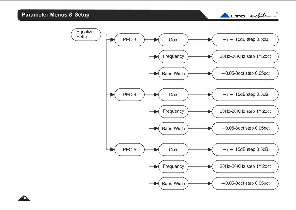
13 LTO Parameter Menus & Setup Equalizer Setup PEQ 3 Gain / 15dB step 0.5dB Frequency 20Hz-20KHz step 1/2oct Band Width oct step 0.05oct PEQ 4 Gain / 15dB step 0.5dB Frequency 20Hz-20KHz step 1/2oct Band Width oct step 0.05oct PEQ 5 Gain / 15dB step 0.5dB Frequency 20Hz-20KHz step 1/2oct Band Width oct step 0.05oct

14 Parameter Menus & Setup LTO Delay Delay Adj 0-99msstep1ms Delay Fine us step 21us Routing Setup Allows setting of the crossover channel routing configuration. For each of the 4 Output Channels you can choose to send just the Left Input signal, the Right Input signal, a combination of both Left and Right Input signals (usually for feeding subwoofers) or no input (OFF). The latter effectively mutes that channel. First select an output channel. Now, using the UP/DOWN buttons to scroll through the list, choose from the routing options. To confirm your choice press ENTER. To cancel your choice press ESC. Input Channel Setup (INPUT L, INPUT R) The following parameter adjustments are available for each input channel. Input Gain 5-band parametric equalization Delay A multi-layer menu system is used. The various layers and the choices within the deepest layer are selected using the UP/DOWN and ENTER keys. Use the ESC (Escape) key to cancel a selection and backtrack up through the menu layers. Gain: Effectively acts as a master balance control. Equalizer setup: From here you can select each of the 5 parametric filters. For each filter you can adjust Gain (cut/boost),
 The following parameter adjustments are available for each input channel.")
15 LTO Parameter Menus & Setup Frequency (the centre frequency of the filter), and Band Width (the extent to which frequencies around the centre frequency will also be adjusted). Delay: This allows a delay to be set on each channel. May be useful in certain circumstances. Also, setting a delay on one side while leaving the other with no delay can produce a very interesting effect of added width and spatial depth. This is not to be confused with 'time alignment' (see under Output Channel Setup). Output Setup (1/2/3/4) Volume / 12dB step 0.5dB Equalizer Setup PEQ 1 Gain / 15dB step 0.5dB Frequency 20Hz-20KHz step 1/12oct Band Width oct step 0.05oct PEQ 2 Gain / 15dB step 0.5dB Frequency 20Hz-20KHz step 1/12oct Band Width oct step 0.05oct
. Output Setup (1/2/3/4) Volume / 12dB step 0.5dB Equalizer Setup PEQ 1 Gain / 15dB step 0.")
16 Parameter Menus & Setup LTO Equalizer Setup PEQ 3 Gain / 15dB step 0.5dB Frequency 20Hz-20KHz step 1/12oct Band Width oct step 0.05oct PEQ 4 Gain / 15dB step 0.5dB Frequency 20Hz-20KHz step 1/12oct Band Width oct step 0.05oct PEQ 5 Gain / 15dB step 0.5dB Frequency 20Hz-20KHz step 1/12oct Band Width oct step 0.05oct
17 LTO Parameter Menus & Setup Output Setup (1/2/3/4) Band Pass Setup High Pass Frequency 20Hz-20KHz step 1/12oct Order Bypass, ord Low Pass Frequency 20Hz-20KHz step 1/12oct Order Bypass, ord Polarity Direct/Invers Compressor Threshold 29dB/0dB step 1dB Release 0.4, 0.5, 0.7, 1.4 sec Attack 0.05, 0.1, 0.2, 0.3 sec

18 Parameter Menus & Setup LTO Delay Delay Adj 0-99msstep1ms Delay Fine us step 21us Output Channel Setup (OUTPUT 1~4) Each channel is capable of being set to operate on any band of frequencies between 20Hz and 20kHz. The following parameter adjustments are available on each output channel. Output Volume Level 5-band parametric equalization Band-Pass Filter (low-pass + high-pass) Polarity (phase) Dynamic processor Delay (time alignment) A multi-layer menu system is used. The various layers and the choices within the deepest layer are selected using the UP/DOWN and ENTER keys. Use ESC to cancel a selection and backtrack up through the menu layers. Volume: Acts as a master system gain control. Can be used as a safety feature to limit the maximum output available when adjusting the panel-mounted gain controls.

19 LTO Parameter Menus & Setup Equalizer setup: From here you can select each of the 5 parametric filters. For each filter you can adjust Gain (cut/boost), Frequency (the centre frequency of the filter), and Band Width (the extent to which frequencies around the centre frequency will also be adjusted). Band Pass setup: Here is where you setup the crossover point and slope for each of the output channels. Use the UP/DOWN keys to select the Low-Pass or High-Pass filter. Now choose the Frequency or Filter Order (slope) and make the desired settings. Your DRIVE20 is delivered from the factory with a default setup (software version 2.0 and above). As a precaution, each output channel has its High-Pass filter switched in at 5,000Hz. When you have finished wiring the channels corresponding to each type of speaker, you must change the default setting of the filter in order to allow bass and lower-mid frequencies to pass. You must then save your system setup as a new User Preset. With the High-Pass filter, the level of frequencies BELOW the crossover point will be reduced at the rate dictated by the st nd rd t h slope setting. 1 Order (6dB), 2 Order (12dB), 3 Order (18dB) or 4 Order (24dB) per octave. With the Low-Pass filter, the level of frequencies ABOVE the crossover point will be reduced at the rate dictated by the slope setting (as above). Either filter can be switched out by setting the Filter Order (slope) to BYPASS. Polarity 0/180 : The polarity or 'phase' of each channel can be switched Direct/Inverse. Compressor setup: This is a form of dynamic processing used extensively in recording studios. It provides a way of controlling the dynamic range by limiting the higher musical peaks to give a more consistent output level. In the car the benefits include the ability to have the volume level high enough to hear softer passages above road and engine noise without having to frantically grab the volume control on loud peaks. Threshold sets the point below full output (0db) where the compressor/limiter begins to operate. Attack and Release determine the time it takes for the compressor/limiter to react to changes in signal level. Generally you can leave Attack and Release at their default settings.
 and make the desired settings. Your DRIVE20 is delivered from the factory with a default setup (software version 2.0 and above).")
20 Parameter Menus & Setup LTO As the music plays, any signal peaks that exceed the level you fixed with your Threshold setting will be reduced by a preset ratio. As well as providing a more consistent listening level, it also helps protect your speakers and will often improve their overall performance. Delay setup: Also known as 'Time Alignment'. This allows a small amount of delay to be set on each of the channels 1-4. The amount of delay is usually calculated from physical measurements of the distances between the various speakers and the driver's ears. The delay compensates for the difference in speaker mounting positions. When applied correctly to all speakers in the system, the result is an improvement in the apparent stage position, height, depth and the location and focus of the performers on the imaginary stage (usually across the dashboard). More information is available via our web site.

21 LTO Installation Instructions Mounting the Unit DRIVE20 has two fixing 'ears' at each side, allowing it to be firmly screwed to a suitable surface. It may be mounted vertically or horizontally. Take care not to mount the unit where it may become wet or subject to damage from items placed in the trunk area. Signal Inputs/Outputs The Left and Right Channel input terminals are standard phono type sockets. Connect the low-level pre-amplifier output cables from your car radio/cassette player, CD/receiver or other source unit to the Input terminals of DRIVE20. This 2-way model has two sets of stereo Outputs and a single mono subwoofer output. Each of these 5 Outputs should be connected to an amplifier input channel. Where to place the DRIVE20 in the signal path The DRIVE20 should be placed into the audio system circuit immediately before the amplifier(s), and after any equalizers or sound processors that you may have. Caution: DRIVE20 must always be placed in line BEFORE the power amplifier stage. Power, Ground and Remote Switch-On (REM) Terminals Caution: Before making any connections, you must stop power delivery from the battery to avoid accidental short-circuits. The conventional way is to disconnect the Negative terminal of the battery but beware - this action will disconnect power from all electrical items in the vehicle, including: the audio source unit (which may require a code number to reactivate it - do you know the code?) the security system (which may trigger and sound an alarm from its back-up battery - do you know how to override the alarm system?) memory modules (which may suffer memory loss if disconnected for too long). If you have any doubts you should seek professional assistance first. Professional auto electricians will isolate individual circuits to maintain power to the remainder of the vehicle's electrical system.
22 Installation Instructions LTO At the far right of the side panel is a POWER INPUT terminal block with three screw terminals. The terminal marked should be connected to a permanent 12 Volt supply from the vehicle battery. 12V The terminal marked GND (Ground) should be connected to a cable which is terminated to the vehicle chassis. Ensure that the point where this cable attaches to the vehicle chassis provides good electrical contact. If drilling a new ground point, ensure that it is safe (check that there is nothing behind the panel you are about to drill, such as the fuel tank). It may be necessary to rub away paintwork to expose the metal at this point - in this case, after making a firm screw connection of the ground cable to the chassis, paint over the terminal point to protect it from the possibility of corrosion. Where a ground point already exists (for an existing power amplifier, for example) it is generally best practice to ground the DRIVE20 to this same point on the vehicle chassis. The terminal marked REM accepts a 12V switched input from the source unit (Cassette or CD player). When the source unit is switched on, a 12V pulse is sent down this line. The DRIVE20 senses this pulse and switches itself on or off. The source unit should be equipped with a suitable Remote Switch cable - check the instruction book supplied with your audio source unit. If the Remote output from the source unit is already being used to switch on a power amplifier, it is usually possible to create a 'daisy-chain' by connecting a cable from the REM or Remote terminal on the amplifier to the REM terminal of the DRIVE20. This avoids the need to run a separate cable from the source unit. Before reconnecting power to the circuit, double check all connections (be particularly careful to check there are no strands of wire that could touch the chassis of the DRIVE20 or one of the other terminals). The power-on LED next to the power input terminal block will light to show the unit is receiving power.
23 LTO RS232 Computer Interface A standard RS232 computer serial interface socket allows connection of DRIVE20 to a computer capable of running Windows compatible software. A dedicated software package is available to setup DRIVE20 more easily using a computer. DRIVE20 should be connected to a suitable computer using a ' null modem' type serial interface cable (supplied). For information about setting up DRIVE20 via a PC, and to download the PC Editor software, visit our web site at
24 Further Information LTO Because of the nature of our digital sound processors and the variety of effects that can be achieved with them, there are operational details, tips and advice too numerous to include in an instruction manual such as this. For additional information, please visit our website at which includes a technical discussion forum where users can exchange ideas. Troubleshooting Power LED not lit: Is the Remote switch cable from the source unit (Cassette or CD Player) attached to the REM terminal of the DRIVE20, and is the source unit switched on? Are the 12V and GND (Ground) terminals connected correctly? Is the Ground cable properly attached to the chassis of the vehicle or to an existing ground point that is known to be OK? No Sound: Adjust the level of the Input Gain Controls. Adjust the level of the Output Gain Controls. Are the Input and Output signal cables correctly connected? If there is only sound from one channel, swap the Left and Right channel Input cables at the DRIVE20 - if the fault moves to the other channel then the fault is with the cable or source unit. If the fault remains in the same channel, isolate which speaker is not working and check back to the amplifier channels that are driving that pair of speakers. Swap the Left and Right channel Output cables at the DRIVE20 feeding those amplifier channels. If the fault still remains on the same speaker then the fault is with a cable or a unit after the DRIVE20 (the power amplifier or the speaker itself). Check the amplifier gain controls and any input switching options (such as built-in crossover networks). If the fault moves to the other speaker then the DRIVE20 may be faulty - leave it installed in your system and return to your dealer so that they can check it. Distorted Sound or Low Volume: Adjust the Input and Output Gain Controls of the DRIVE20, and the Input Level Controls of the power amplifier (and input/output controls of any additional processor, if applicable). Check if the amplifier has a built-in crossover network - is it switched correctly?
25 LTO Your ALTO R Warranty To be protected by this warranty, the buyer must be able to produce a numbered, machine printed sales receipt (original only accepted, not a copy) from his supplying dealer that clearly shows the dealer's name and address, the buyer's name R and address, purchase date, model name/number and serial number of the product. ALTO reserves the right to verify the authenticity of the receipt directly with the supplying dealer. R ALTO warrants the mechanical and electronic components of this product to be free of defects in material and workmanship for a period of one (1) year from the original date of purchase. If any defects occur within the specified warranty R period that are not caused by normal wear and tear or inappropriate use, ALTO shall, at its sole discretion, either repair or replace the product. To obtain warranty service, the product must be returned in its original shipping carton. A description of the problem will be appreciated. Damages/defects caused by the following conditions are not covered by this warranty: a. Misuse, neglect or failure to operate the unit in compliance with the instructions given in the user or service manuals. b. Connection or operation of the unit in any way that does not comply with the technical or safety regulations applicable in the country where the product is used. R c. Damages/defects that are caused by force majeure or by any other condition beyond the control of ALTO. Any repair carried out by unauthorised personnel will void the warranty. This warranty is extended exclusively to the original buyer (customer of retail dealer) and is not transferable to anyone who may subsequently purchase this product. No other person (retail dealer, etc.) shall be entitled to give any warranty R promise on behalf of ALTO. R Failure of ALTO to provide proper warranty service shall not entitle the buyer to claim (consequential) damages. In no R event shall the liability of ALTO exceed the invoiced value of the product. This warranty does not exclude or limit the buyer's statutory rights provided by national law, in particular, any such rights against the seller that arise from a legally effective purchase contract.
26 Specifications LTO Channel Layout Input section for each channel: EQ Filters: Delay line: Output section for each channel: Delay line: Band Pass Filters: EQ Filters: Polarity Limiter Output digital volume Mute 2 inputs 4 outputs 1 subwoofer output Biquadratic Bell Filters type III additive Gain: / 15dB step 0.5dB Frequency: 20Hz to 20KHz minimum step 1/12oct Bandwidth: 0.05oct to 3oct step 0.05oct 0-99 ms step 1 ms ( fine step 21 us ) 0-99 ms step 1 ms ( fine step 21 us ) Butterworth up to 4th order ( 24dB/oct ) Frequency: 20Hz to 20KHz, step 1/1 2oct Biquadratic Bell Filters type III additive Gain: / 15dB step 0.5dB Frequency: 20Hz to 20KHz, minimum step 1/1 2oct Bandwidth: 0.05oct to 3oct step 0.05oct Direct / Inverse Variable limiting level / 12dB step 0.5dB ON /OFF
27 LTO Specifications Analog Input section Inputs: Input Impedance: Max. input Level: Analog Output section Outputs: Output Impedance: Max. output level: Digital / Analog Interface Amplitude Response: Signal to Noise Ratio THD N Conversion Conversion 2 RCA - F 400 kohms 15 V 5 RCA - F 600 Ohms 9.5 V 20 Hz - 20KHz 1.5 db 85 db KHz (-3 db) input 20 bits Sigma - Delta output 24 bits Sigma - Delta Remote Control -RS 232 for PC Connection (user interface on PC screen with MS 9X-OS) Power Supply Type: Voltage supply: Servo - controlled, Switching 11V - 16V DC (negative ground) 26
28 SEIKAKU ELECTRON INDUSTRY (H.K.) CO., LTD. No. 1, Lane 17, Sec. 2, Han Shi W. Road, Taichung, 401 Taiwan Tel: Fax: All rights reserved to ALTO Mobile. Due to continued development in response to customer feedback, product features and/or internal/external design may be changed without prior notice. No photocopying, translation or reproduction of any part of this user manual is allowed without prior written permission.copyright c 2004 Seikaku Electron. NF
************* OWNER'S MANUAL BAMF800/2 BAMF1250/2 BAMF1800/2 BAMF2200/2 BAMF2600/2 BAMF1200/4 BAMF1600/4 BAMF2000/1D BAMF4000/1D BAMF5500/1D
 ************* OWNER'S MANUAL BAMF800/2 BAMF1250/2 BAMF1800/2 BAMF2200/2 BAMF2600/2 BAMF1200/4 BAMF1600/4 BAMF2000/1D BAMF4000/1D BAMF5500/1D INTRODUCTION Power Acoustik amplifiers provide high-performance
OWNER'S MANUAL HIGH PERFORMANCE AMPLIFIERS
 OWNER'S MANUAL HIGH PERFORMANCE AMPLIFIERS B2 has through years of dedication introduced our line of Ref 0.5 & Anno amplifiers. The B2 line up are made to fullfil our philosophy for amplifiers; A variety
JAD SERIES OWNER S MANUAL. JAD900.5 5 Channel Full Range Class D Amplifier
 JAD SERIES OWNER S MANUAL JAD900.5 5 Channel Full Range Class D Amplifier Authorized Dealer Name: Purchase Date: Model Number: Serial Number: JAD900.5 PERFORMANCE MODEL: RMS Power (4 Ohms, Stereo) RMS
MPA-101. WARNING: Improper installation could result in damage to the amplifier and/or speakers. Read all instructions before installation.
 MPA-101 WARNING: Improper installation could result in damage to the amplifier and/or speakers. Read all instructions before installation. The lightning flash with arrowhead, within an equilateral triangle,
Operation Manual for Users
 Operation Manual for Users Model No.: FLTAMFMRCD!!!!!!!!!! ATTENTION!!!!!!!!!! THE RESET BUTTON MUST BE PRESSED TO ENSURE PROPER OPERATION. SEE INSTRUCTION MANUAL Table of Contents Table of Contents ---------------------------------------------------------------------------------------------
USA 305. Power Amplifier OWNERS MANUAL AND INSTALLATION GUIDE PARALLEL/SERIES WIRING DIAGRAMS. two 4 ohm woofers in parallel = 2 ohms
 PARALLEL/SERIES WIRING DIAGRAMS USA 305 two 4 ohm woofers in parallel = 2 ohms two 4 ohm woofers in series = 8 ohms SOUNDSTREAM TECHNOLOGIES 120 Blue Ravine Road Folsom California 95630 USA ph 916.351.1288
www.vibeaudio.co.uk OPTISOUND AUTO 8 Model: OPTISOUNDAUTO8-V2 OPTISOUND AUTO 8 ACTIVE Model: OPTISOUNDAUTO8A-V2
 C O M P A C T B A S S R E F L E X S U B W O O F E R E N C L O S U R E S O W N E R S M A N U A L OPTISOUND AUTO 8 Model: OPTISOUNDAUTO8-V2 OPTISOUND AUTO 8 ACTIVE Model: OPTISOUNDAUTO8A-V2 To ensure maximum
Q1-750 Q1-1200.2 Q1-2200.2 Q1-4500 Q2-200 Q4-90 Q4-120 HIGH PERFORMANCE AMPLIFIER
 Owner s Manual Q1-750 Q1-1200.2 Q1-2200.2 Q1-4500 Q2-200 Q4-90 Q4-120 HIGH PERFORMANCE AMPLIFIER INTRODUCTION Thanks you for purchasing SoundQubed amplifiers for your car audio systems and competitions
LSM-480 USER MANUAL. A.D.J. SUPPLY EUROPE B.V. Junostraat 2 6468 EW Kerkrade The Netherlands www.americanaudio.eu
 LSM-480 USER MANUAL A.D.J. SUPPLY EUROPE B.V. Junostraat 2 6468 EW Kerkrade The Netherlands www.americanaudio.eu 1 2 Table of Contents Table of Contents... 3 1.0 Introduction...4 2.0 Features...5 3.0 Front
Contents. Mission Statement...2. Warnings... 4. Wire Size...5. Installation Guidelines... 6. i-force Inputs...9. Bass Boost Control...10. i-force...
 Contents Mission Statement...2 Warnings... 4 Wire Size...5 Installation Guidelines... 6 i-force Inputs...9 Bass Boost Control...10 i-force...11 i-250...11 i-2100...14 i-450...17 i-4100...20 i-5100...23
BXR 300C BXR 300R. Owner, s Manual P/N 040294
 THE SOUND THAT CREATES LEGENDS BXR 300C BXR 300R Owner, s Manual P/N 040294 INTRODUCTION The Fender BXR 300 AMPLIFIER is the most recent effort in state of the art bass amplifier technology, and is a member
CLASS-D MONO BLOCK POWER AMPLIFIERS BZA-1000D / BZA-2000D OWNER'S MANUAL
 CLASS-D MONO BLOCK POWER AMPLIFIERS BZA-1000D / BZA-2000D OWNER'S MANUAL Table of Contents Table of Contents Introduction & Features Specification Features & Controls Installation & Precautions System
MODEL 2202IQ (1991-MSRP $549.00)
") F O R T H E L O V E O F M U S I C F O R T H E L O V E O F M U S I C MODEL 2202IQ (1991-MSRP $549.00) OWNER'S MANUAL AND INSTALLATION GUIDE INTRODUCTION Congratulations on your decision to purchase a LINEAR
F O R T H E L O V E O F M U S I C F O R T H E L O V E O F M U S I C MODEL 2202IQ (1991-MSRP $549.00) OWNER'S MANUAL AND INSTALLATION GUIDE INTRODUCTION Congratulations on your decision to purchase a LINEAR
LOXONE 12 Channel Amplifier
 LOXONE 12 Channel Amplifier Item no.: 200110 Thank you for purchasing the Loxone Twelve Channel Amplifier. The versatility of the Amplifier makes it the perfect choice for almost every type of custom multi-room
INTRODUCTION. Please read this manual carefully for a through explanation of the Decimator ProRackG and its functions.
 INTRODUCTION The Decimator ProRackG guitar noise reduction system defines a new standard for excellence in real time noise reduction performance. The Decimator ProRackG was designed to provide the maximum
Owner s Manual 900.4. 4 channel amplifier
 Owner s Manual 900.4 4 channel amplifier THANK YOU Limited Warranty: for purchasing RE AUDIO Bluetooth amplifiers BT-900.4. With almost no sacrifice on sound quality, BT-900.4 easily plays the music from
2 X 250Watt Class D Audio Amplifier Board IRS2092 User s Guide
 2 X 250Watt Class D Audio Amplifier Board IRS2092 User s Guide 2004-2013 Sure Electronics Inc. AA-AB32291_Ver1.0 2 X 250Watt Class D Audio Amplifier Board IR2092 Note: Please read this manual carefully
Understanding the DriveRack PA. The diagram below shows the DriveRack PA in the signal chain of a typical sound system.
 Understanding the DriveRack PA The diagram below shows the DriveRack PA in the signal chain of a typical sound system. The diagram below shows all the pieces within a sound system that the DriveRack PA
Contents. Safety Warnings... 1
 Contents Safety Warnings... 1 Unpacking the GQ600... 1 Introduction... 2 GQ600 Filter Characteristics... 2 1/3 Octave Centre Frequencies... 4 Front Panel Functions... 5 Rear Panel Functions... 6 Specifications...
MAC 2.2/2.3/2.4 PROFESSIONAL STEREO AMPLIFIERS
 MAC././.4 PROFESSIAL STEREO AMPLIFIERS OWNER'S MANUAL www.altoproaudio.com Version. NOV 007 English IMPORTANT SAFETY INSTRUCTI CAUTI RISK OF ELECTRIC SHOCK DO NOT OPEN TO REDUCE THE RISK OF ELECTRIC SHOCK
To reduce the risk of electrical shocks, fire, and related hazards:
 Owner s Manual 1 Contents 1. Safety Notes 5 2. Introduction 6 3. Features 7 4. Installation Guide 8 5. Front Panel Explained 9 6. Rear Panel Explained 10 7. Software Control Panel 12 8. Advanced User Tips
Active Monitor Box McCrypt S.T.E.V.E. 15. Order No. 30 17 06
 Active Monitor Box McCrypt S.T.E.V.E. 15 Order No. 30 17 06 1 McCrypt Active Monitor 15 Introduction Dear Customer, Thank you for purchasing this McCrypt Active Monitor. You have chosen a quality product
EC4.8. BalancedReferencePreamplifier. Owner smanual ENG
 EC4.8 BalancedReferencePreamplifier Owner smanual ENG Unpacking the EC 4.8 Immediately upon receipt of the EC 4.8, inspect the carton for possible damage during shipment. The carton and packaging have
Wireless Home Security System Product Manual (Model #80355)
") Wireless Home Security System Product Manual (Model #80355) Installation Instructions During set-up, if no key is pressed for 15 seconds it will come out of the setup mode and you will have to start over.
Wireless Home Security System Product Manual (Model #80355) Installation Instructions During set-up, if no key is pressed for 15 seconds it will come out of the setup mode and you will have to start over.
ACTIVE. www.edgecaraudio.com
 ACTIVE www.edgecaraudio.com INTRODUCTION This instruction manual is for your safety and must be adhered to at all times. Please read and ensure that you fully understand the installation and set up procedures
AVR 158. Audio/video receiver. Quick-Start Guide ENGLISH
 158 Audio/video receiver ENGLISH Quick-Start Guide 158 Introduction, Speaker Placement and Connection Introduction Thank you for choosing a harman kardon product! This quick-start guide contains all the
i ChatterBox! Motorcycle Security
 i Before you Start the Installation * Please read this manual to become familiar with the requirements necessary to complete the installation. * Use a high quality multi-meter to test all wires before
THE MclNTOSH MC 2100 SOLID STATE STEREO POWER AMPLIFIER
 THE MclNTOSH MC 2100 SOLID STATE STEREO POWER AMPLIFIER Price $1.25 Your MC 2100 stereo amplifier will give you many years of pleasant and satisfactory performance. If you have any questions concerning
DCP-24 ORDERCODE D2080 Highlite International B.V.
 DCP-24 ORDERCODE D2080 Highlite International B.V. Vestastraat 2 6468 EX Kerkrade The Netherlands Congratulations! You have bought a great, innovative product from DAP Audio. The DAP Audio DCP-24 brings
RVA600.1 4 OHM MONOBLOCK
 RVA600.1 4 OHM MONOBLOCK Introduction Thank you for purchasing this Rockville RVA600.1 amplifier. Over the years, the technology used to create audio amplifiers has grown by leaps and bounds. Our competition
PLA-4350. PLA-4300D Class-D Mono Block Power Amplifier. Two Channel High Performance Power Amplifier. Four Channel High Performance Power Amplifier
 PLA- 2 1 9 PLA-2250 PLA-2450 PLA-2650 PLA-2150 PLA-2350 PLA-2550 PLA-2750 PLA-2850 Two Channel High Performance Power Amplifier PLA- 4 1 9 PLA-4250 PLA-4150 PLA-4350 Four Channel High Performance Power
Phoenix Gold International, Inc. (or "Phoenix Gold") warrants its products against defects in materials and workmanship for a limited period of time.
 warrants its products against defects in materials and workmanship for a limited period of time.") Phoenix Gold International, Inc. (or "Phoenix Gold") warrants its products against defects in materials and workmanship for a limited period of time. For a period of one (1) year from date of original
Phoenix Gold International, Inc. (or "Phoenix Gold") warrants its products against defects in materials and workmanship for a limited period of time. For a period of one (1) year from date of original
GAMING INSTRUCTION. www.vibeaudio.co.uk. Model: OPTISOUNDGAME5-V1
 INSTRUCTION MANUA L 1 5 Model: OPTISOUNDGAME5-V1 www.vibeaudio.co.uk To ensure maximum performance and safety, please follow this manual. Please retain the manual for future reference after installation
OPERATING INSTRUCTIONS
 OPERATING INSTRUCTIONS OPERATING INSTRUCTIONS MAG & Electric Blue Amplifier Heads and Combos Thank you for purchasing your Ashdown Engineering Amplifier. If you live in the UK, please register your purchase
STEREO PREAMPLIFIER INSTRUCTIONS FOR USE
 XX STEREO PREAMPLIFIER INSTRUCTIONS FOR USE Thank you for purchasing the Musical Fidelity A5 CR Preamplifier. Used properly and carefully, it should give many years of outstanding musical reproduction.
Hegel H1 High End Integrated Amplifier
 Hegel H1 High End Integrated Amplifier www.hegel.com [email protected] USER GUIDE Congratulations on your new HEGEL! Our products are based on a simple philosophy: The component shall reproduce the original
BXR. Owner, s Manual. One hundred BASS EXTENDED RANGE P/N 040695
 THE SOUND THAT CREATES LEGENDS BASS EXTENDED RANGE BXR One hundred Owner, s Manual P/N 040695 BXR 100 Owner s Manual Congratulations on your purchase of the Fender BXR 100 Bass amplifier. The Fender BXR
VK-250 WARRANTY REGISTRATION FORM
 VK-250 WARRANTY REGISTRATION FORM Unit Serial Number: Customer Name: Address: Date of Purchase: Purchased From: Dealer Name: Address: IMPORTANT NOTE: In order to receive the full five year product warranty,
Owner's manual. ST-series D
 Owner's manual ST-series D Great Sound - Big Power - Compact Chassis Before operating the unit, please read this manual throughly and retain it for future reference. Protect your Investment Note your information
user guide Meridian 558 Multi Channel Power Amplifier
 user guide Meridian 558 Multi Channel Power Amplifier Meridian 558 Multi Channel Power Amplifier User Guide ipreface Sales and service in the UK Meridian Audio Ltd Stonehill Stukeley Meadows Cambs PE18
Using Your Fitting Software This guide provides comprehensive, task-based information about all the fitting software features.
 Gravity Fitting Software User's Manual part #: S0273-01 Rev A Using Your Fitting Software This guide provides comprehensive, task-based information about all the fitting software features. You may access
W8VDQ. User s Guide. The Martin Experience. All material 2008. Martin Audio Ltd. Subject to change without notice.
 W8VDQ User s Guide The Martin Experience W8VDQ User Guide Contents 1 Unpacking 2 Introduction 3 Safety first 3.1 Pole mounting 3.2 Free standing 3.3 Yoke assembly 4 Aiming for best coverage 5 Amplification
ECD 2 High Performance Balanced DAC. 24 Bit /192kHz. Owner's Manual
 ECD 2 High Performance Balanced DAC 24 Bit /192kHz Owner's Manual EN Unpacking the ECD 2 Immediately upon receipt of the ECD 2, inspect the carton for possible damage during shipment. If the carton is
User s Guide. for amplifiers. SPL 3000c1
 User s Guide for amplifiers FETURES Digital class-d linkable mono block amplifier Dual MOS-FET PWM power supplies Daisy-chain through output Jack Stable into 1 ohm and 2 ohms load 24d/oct variable crossover
Internet store of autogoods
 PHONES (044) 360-7-130 (050) 336-0-130 (063) 788-0-130 (067) 233-0-130 (068) 282-0-130 Internet store of autogoods ICQ 294-0-130 597-0-130 SKYPE km-130 CAR RECEIVERS Receivers Media receivers and stations
BSS performance, from club to conference
 BSS performance, from club to conference Minidrive is specifically designed for smaller touring and installed sound applications which nonetheless demand the unique power and flexibility of BSS loudspeaker
VIEW. SLX300 SpeakerLinX IP Zone. Amplifier Installation and Setup Guide. AVoIP
 VIEW SLX300 SpeakerLinX IP Zone Amplifier Installation and Setup Guide TM AVoIP ClearOne 5225 Wiley Post Way Suite 500 Salt Lake City, UT 84116 Telephone 1.800.283.5936 1.801.974.3760 Tech Sales 1.800.705.2103
EARTHQUAKE SOUND PowerHouse Series Amplifiers Owners Manual
 EARTHQUAKE SOUND PowerHouse Series Amplifiers Owners Manual MODELS: PH800W/2 PH1000W/2 PH2200W/4 PH2000W/D1 PH2000W/D1.1 PH5000W/D1 PH10000W/D1 PH20000W/D1 The Sound That Will Move You. Earthquake Sound
Auto Dialer. Manual E-921APQ E-921GPQ
 Troubleshooting: Auto dialer will not arm/disarm Auto dialer will not dial out Unit doesn t respond to a call-back Difficulty in activating room monitor by telephone remote control Make sure that you have
RIGOL. Quick Guide. DS1000CA Series Oscilloscope. Aug. 2011. RIGOL Technologies, Inc.
 Quick Guide DS1000CA Series Oscilloscope Aug. 2011 Technologies, Inc. Guaranty and Declaration Copyright 2011 Technologies, Inc. All Rights Reserved. Trademark Information is a registered trademark of
Tone Hammer 500. Owners Manual. Manual Version 1.0
 Tone Hammer 500 Owners Manual Manual Version 1.0 1. Incorporating the preamp from the popular Tone Hammer preamp/di pedal this superlight bass head combines three bands of flexible EQ, a colorful "Drive"
The completely Ethernet-based. protocol enables several imode devices to be linked, using easily-sourced. cables and components.
 WHAT IS imode? Outline imode is proprietary technology, conceived to re-think the state of the art in the world of loudspeaker system control. Devices using this technology have a single on-board DSP that
LEN s.r.l. Via S. Andrea di Rovereto 33 c.s. 16043 CHIAVARI (GE) Tel. +39 0185 318444 - Fax +39 0185 472835 mailto: [email protected] url: http//www.len.
 Tel. +39 0185 318444 - Fax +39 0185 472835 mailto: len@len.it url: http//www.len.") MA511 General Index 1 INTRODUCTION... 3 1.1 HARDWARE FEATURES:... 4 2 INTERFACE... 5 2.1 KEYBOARD... 6 2.2 POWER ON... 7 2.3 POWER OFF... 7 2.4 DETECTOR CONNECTION... 7 2.5 DETECTOR SUBSTITUTION...7 3
MA511 General Index 1 INTRODUCTION... 3 1.1 HARDWARE FEATURES:... 4 2 INTERFACE... 5 2.1 KEYBOARD... 6 2.2 POWER ON... 7 2.3 POWER OFF... 7 2.4 DETECTOR CONNECTION... 7 2.5 DETECTOR SUBSTITUTION...7 3
Gemini II. Subwoofer System OWNERS MANUAL
 Gemini II Subwoofer System OWNERS MANUAL CONTENTS Page No. 1) Safety instructions. 2) 3) 4) Connecting up your Gemini II. Connecting up using the high level input. Connecting up using the low level input.
HIGH PERFORMANCE CAR AUDIO MODEL:CR-82 8 CHANNEL ELECTRONIC CROSSOVER NETWORK SYSTEM. www.pyramidcaraudio.com
 HIGH PERFORMANCE CAR AUDIO MODEL:CR-82 8 CHANNEL ELECTRONIC CROSSOVER NETWORK SYSTEM 1 www.pyramidcaraudio.com INTRODUCTION This CR-82 is an Electronic Crossover Network with which you can install various
MOBILE POWER AMPLIFIERS
 MOBILE AMPLIFIERS 2 X 165 WATT 2 CHANNEL AMPLIFIER 4 X 140 WATT 4 CHANNEL AMPLIFIER 2 X 250 WATT 2 CHANNEL AMPLIFIER 4 X 250 WATT 4 CHANNEL AMPLIFIER 2 X 425 WATT 2 CHANNEL AMPLIFIER 4 X 150 WATT 1 X 300
X 1400 X 2400 4-Channel Amplifier Instruction Manual
 INNOVATIVE AUDIO PERFORMANCES MADE IN GERMANY X 1400 X 2400 4-Channel Amplifier Instruction Manual Introduction Contents Dear Customer, Congratulations on your purchase of this high-quality BRAX product.
High Power Receiver CR-W400U Operating Instructions
 High Power Receiver CR-W400U Operating Instructions Please read these instructions carefully before using this product and save this manual for future use. Panasonic welcomes you to our ever growing family
HUMAN REIGN HR 2 HR 4
 HUMAN REIGN HR 2 HR 4 Owner s Manual and Installation Guide Congratulations! You now own the Soundstream Human Reign amplifier, the product of an uncompromising design and engineering philosophy. Your
DPX1000.2 Power System Amplifier
 DPX1000.2 Power System Amplifier INTRODUCTION The Clarion DPX1000.2 is a full-featured two-channel amplifier that. incorporates the following features: INTRODUCTION Digital Technology for high efficiency
MANUAL PC1000R [email protected]
 MANUAL PC1000R [email protected] Features The APart PC1000R is a professional multisource CD/USB/SD card music player, equipped with balanced and unbalanced analog outputs, coaxial and optical digital
Business Audio System: Music & Messaging MP3 Player. by Grace Digital Audio. User Guide. Model No. GDI-USBM10
 Business Audio System: Music & Messaging MP3 Player by Grace Digital Audio User Guide Model No. GDI-USBM10 User Guide Contents Introduction 2 Safety & General Use Information 2 Features 3 Set Up & Operation
APPLICATION GUIDE. Subwoofer-Satellite Systems. Using Control SB-210 & SB-2 Subwoofers. System #5 in Stereo
 APPLICATION GUIDE Subwoofer- Systems Using Control SB-210 & SB-2 Subwoofers System #5 in Stereo SPL (at 20 Feet): 94 db Continuous (peaks of 104 db) Stereo / Mono Selector: Stereo 4-Ohm / 8-Ohm Selector:
How To Control The Jbl Professional Dsc280 System Controller On A Pc Or Mac Or Ipad (For Pc Or Ipa) With A Dsc 280 (For Mac Or Mac) With An Dsc28 (For Ipa Or Ip
 With A Dsc 280 (For Mac Or Mac) With An Dsc28 (For Ipa Or Ip") Controlling the JBL Professional DSC280 System Controller Using SIA-Smaart Pro SIA Software Company, Inc. an EAW Company The SIA-Smaart Pro Real-Time module can control crossover and delay functions on
Controlling the JBL Professional DSC280 System Controller Using SIA-Smaart Pro SIA Software Company, Inc. an EAW Company The SIA-Smaart Pro Real-Time module can control crossover and delay functions on
LSR4300 Control Center Software
 LSR4300 Control Center Software User Guide Updated for version 2.0 software Table Of Contents Introduction...3 System Requirements...4 Installation...4 Launching The Software...5 Reference...7 Main Screen...7
Evolution Digital HD Set-Top Box Important Safety Instructions
 Evolution Digital HD Set-Top Box Important Safety Instructions 1. Read these instructions. 2. Keep these instructions. 3. Heed all warnings. 4. Follow all instructions. 5. Do not use this apparatus near
CAUTION RISK OF ELECTRIC SHOCK NO NOT OPEN
 Evolution Digital HD Set-Top Box Important Safety Instructions 1. Read these instructions. 2. Keep these instructions. 3. Heed all warnings. 4. Follow all instructions. 5. Do not use this apparatus near
Smarthome SELECT Bluetooth Wireless Stereo Audio Receiver and Amplifier INTRODUCTION
 Smarthome SELECT Bluetooth Wireless Stereo Audio Receiver and Amplifier INTRODUCTION The Smarthome SELECT Bluetooth Wireless Stereo Audio Receiver and Amplifier is a multi-functional compact device. It
Brio-Rmanual:Cursamanual.qxd 08/04/2011 09:25 Page1
 - Brio-Rmanual:Cursamanual.qxd 08/04/2011 09:25 Page1 Brio-Rmanual:Cursamanual.qxd 08/04/2011 09:25 Page2 CONTENTS INTRODUCTION, FEATURES AND TECHNOLOGY 1-3 INSTALLATION 3 CONNECTIVITY 4-6 LOUDSPEAKER
IMPORTANT SAFETY INSTRUCTIONS
 IMPORTANT SAFETY INSTRUCTIONS When using this electronic device, basic precautions should always be taken, including the following: 1. Read all instructions before using the product. 2. Do not use this
Desktop Headphone amplifier with Advanced DAC
 HugoTT Instruction Manual Desktop Headphone amplifier with Advanced DAC Thank you for purchasing the Chord HugoTT. In order to get the most from your product, please take a few moments to read the instructions.
XLS200 MKII. Subwoofer System OWNERS MANUAL
 XLS200 MKII Subwoofer System OWNERS MANUAL CONTENTS Page No. 1) Safety instructions. 2) 3) 4) Connecting up your XLS200. Connecting up using the high level input. Connecting up using the low level input.
XPanel V2. Remote Control Panel. User Manual. XILICA Audio Design
 XPanel V2 Remote Control Panel User Manual XILICA Audio Design Important Safety Instructions 1. READ THESE INSTRUCTIONS All the safety and operating instructions should be read before the product is operated.
Generic - Hearing Loop - (AFILS) U.S. System Specification
 U.S. System Specification") This document is a generic specification for any Hearing Loop (Audio Frequency Induction Loop System). For the remainder of the document, we will refer to using the term Hearing Loop rather than Audio
This document is a generic specification for any Hearing Loop (Audio Frequency Induction Loop System). For the remainder of the document, we will refer to using the term Hearing Loop rather than Audio
MCA Series Multi-Channel Amplifiers. Operation Manual
 MCA Series Multi-Channel Amplifiers Operation Manual February 2012 Biamp Systems, 9300 SW Gemini Drive, Beaverton, Oregon 97008 U.S.A. (503) 641-7287 www.biamp.com IMPORTANT SAFETY INSTRUCTIONS IMPORTANT
INSTALLATION GUIDE. Freestanding Subwoofer
 INSTALLATION GUIDE RCC300-SM RCC300-FS RCC300-SA RCC300-CM Subwoofer Module Freestanding Subwoofer Subwoofer Amplifier Cabinet Mount 2 Thank you for choosing Artison s RCC 300 Subwoofer System. We are
DX1400, DX700, DX350
 DX1400, DX700, DX350 Class D Subwoofer Amplifiers One of the hardest problems to overcome in a high power car stereo system is providing the tremendous amount of current necessary to feed high power amplifiers.
AW-100 DUAL MONO BALANCED POWER AMPLIFIER. Owner s Manual
 AW-100 DUAL MONO BALANCED POWER AMPLIFIER Owner s Manual WARNING: To reduce risk of fire or electric shock, do not expose this appliance to rain or moisture. Verify line voltage before use. Do not remove
Perseus. Owner s Manual. Vacuum Tube Preamplifier. Rogue Audio, Inc. 3 Marian Lane Brodheadsville, PA 18322. Issue date: 02/01/06
 Perseus Vacuum Tube Preamplifier Owner s Manual Rogue Audio, Inc. 3 Marian Lane Brodheadsville, PA 18322 Issue date: 02/01/06 TABLE OF CONTENTS 1) Introduction 2 2) Unpacking the Perseus Preamplifier 2
Weather Radio Alarm Clock
 1200093 User s Guide Weather Radio Alarm Clock Thank you for purchasing your Weather Radio Alarm Clock from RadioShack. Please read this user s guide before installing, setting up, and using your new weather
Zone Mixer. 6 channels configurable from 24 inputs. 3 zone outputs. Expandable via Sys-Link TM Built-in comp/limiter, ducking and alarm functions
 GR 1 Zone Mixer W H E N Y O U R E M I X I N G W I T H P R O F E S S I O N A L S 6 channels configurable from 24 inputs. 3 zone outputs. Expandable via Sys-Link TM Built-in comp/limiter, ducking and alarm
KEYBOARD EXTENDED RANGE. Sixty Owner, s Manual P/N 049254
 THE SOUND THAT CREATES LEGENDS KEYBOARD EXTENDED RANGE Sixty Owner, s Manual P/N 049254 INTRODUCTION Your new Fender KXR 60 Keyboard Amplifier is the result of Fender s ongoing dialog with many of today
FAQs. XAP Frequently Asked Questions. Software/Configuration
 XAP Frequently Asked Questions ~ Software/Configuration ~ Echo Cancellation ~ Audio Performance ~ Expansion Bus ~ Firmware ~ Installation ~ Presets ~ Telephone Hybrid Software/Configuration What is the
MIDI control allows the Split Personality to be used remotely in rack systems, or integrated into MIDI controlled setups for easy preset recall.
 Introduction Trying to drive multiple amplifiers can typically be a frustrating experience. The Decibel Eleven Split Personality is an active AB/Y switcher that enables musicians to run multiple amplifiers
Automatic AES Change-Over
 Automatic AES Change-Over Thank you for choosing a GHIELMETTI product. We are convinced that your choice will prove to be a wise and worthy decision for many years to come. Your GHIELMETTI product has
Firmware version: 1.10 Issue: 7 AUTODIALER GD30.2. Instruction Manual
 Firmware version: 1.10 Issue: 7 AUTODIALER GD30.2 Instruction Manual Firmware version: 2.0.1 Issue: 0.6 Version of the GPRS transmitters configurator: 1.3.6.3 Date of issue: 07.03.2012 TABLE OF CONTENTS
RX-18B ORDERCODE D3314
 RX-18B ORDERCODE D3314 Congratulations! You have bought a great, innovative product from DAP Audio. The DAP Audio RX-18B brings excitement to any venue. Whether you want simple plug-&-play action or a
Owner s Manual Please read before using this equipment. 4-Channel Stereo Mixer
 Owner s Manual Please read before using this equipment. 4-Channel Stereo Mixer ˆ Features Your RadioShack 4-Channel Stereo Mixer is a sophisticated desktop control center, perfect for mixing sound on four
Conference Phone UserÕs Manual. Part No. 54-2070-01R1 Printed in Korea. 2002 Bogen Communications, Inc.
 Part No. 54-2070-01R1 Printed in Korea. 2002 Bogen Communications, Inc. UserÕs Manual Notice Every effort was made to ensure that the information in this guide was complete and accurate at the time of
CMP30. User Manual. www.audac.eu
 CMP30 User Manual www.audac.eu 2 Index Introduction 4 Precautions 5 Safety requirements 5 Caution servicing 5 EC Declaration of Conformity 5 Waste of Electrical and Electronic Equipment (WEEE) 6 Caution
Amplifier: AMP-8125. Feature Summary
 Savant Systems AMP-825 is a multi-room amplifier for distributed audio applications. The AMP-825 is an ultraefficient Class D amplifier delivering 8 channels of reliable amplification rated at 25 watts
VideoMate V200/V200F Analog Standalone TV Box Start Up Guide
 VideoMate V200/V200F Analog Standalone TV Box Start Up Guide Compro Technology, Inc. www.comprousa.com 1 Table of Contents About This Guide... 3 VideoMate V200/V200F TV Box Contents... 4 Install V200/V200F
ATB10AJ / ATB12AJ OWNER S MANUAL PLEASE READ THIS MANUAL BEFORE OPERATING THIS UNIT. RETAIN FOR FUTURE REFERENCE.
 ATB10AJ / ATB12AJ OWNER S MANUAL PLEASE READ THIS MANUAL BEFORE OPERATING THIS UNIT. RETAIN FOR FUTURE REFERENCE. The Audiobahn Way To bring the product to market that excites the consumer through sound
CINEMA SB100 powered soundbar speaker
 CINEMA SB100 powered soundbar speaker quick-start guide Thank You For Choosing This JBL Product The JBL Cinema SB100 powered soundbar speaker is a complete, integrated sound system that will dramatically
PS 155 WIRELESS INTERCOM USER MANUAL
 PS 155 INTERFACE TO SIMPLEX WIRELESS INTERCOM USER MANUAL Issue 2011 ASL Intercom BV DESIGNED AND MANUFACTURED BY: ASL INTERCOM BV ZONNEBAAN 42 3542 EG UTRECHT THE NETHERLANDS PHONE: +31 (0)30 2411901
MONITOR STATION. Studio Control Center. User s Manual v1.0. 2007, PreSonus Audio Electronics, Inc. All Rights Reserved.
 MONITOR STATION Studio Control Center User s Manual v1.0 2007, PreSonus Audio Electronics, Inc. All Rights Reserved. PRESONUS LIMITED WARRANTY PreSonus Audio Electronics Inc. warrants this product to be
600-GD & 600-GDL 600 SERIES GAS DETECTOR
 600-GD & 600-GDL 600 SERIES GAS DETECTOR INSTALLATION AND OPERATING INSTRUCTIONS This page has been deliberately left blank. Page 1 Table of Contents 1 WARRANTY...3 2 IMPORTANT...3 3 CAUTIONS WHEN USING
AM / FM Tuner + RDS. Model: TU-101. www.pulse-audio.co.uk
 AM / FM Tuner + RDS Model: TU-101 www.pulse-audio.co.uk 1 Safety Information The lightning bolt within a triangle is intended to alert the user to the presence of dangerous voltage levels within the product
Memcom Emergency Telephone
 Memcom Emergency Telephone Installation Guide Ref No. 450 900 (GB) Version 2 + + Simple wiring for quick installation + + Integrated LCD display shows you what you have programmed + + All code based programming
CR9986 ROBERTS. Dual Alarm CD Clock Radio. Sound for Generations. Please read this manual before use
 ROBERTS Sound for Generations CR9986 Dual Alarm CD Clock Radio Please read this manual before use Contents Contents... Controls... - Switching on and setting the time... 4 Listening to the radio... 5 Compact