MPA SERIES MIXER-AMPLIFIER
|
|
|
- Ann Anthony
- 10 years ago
- Views:
Transcription
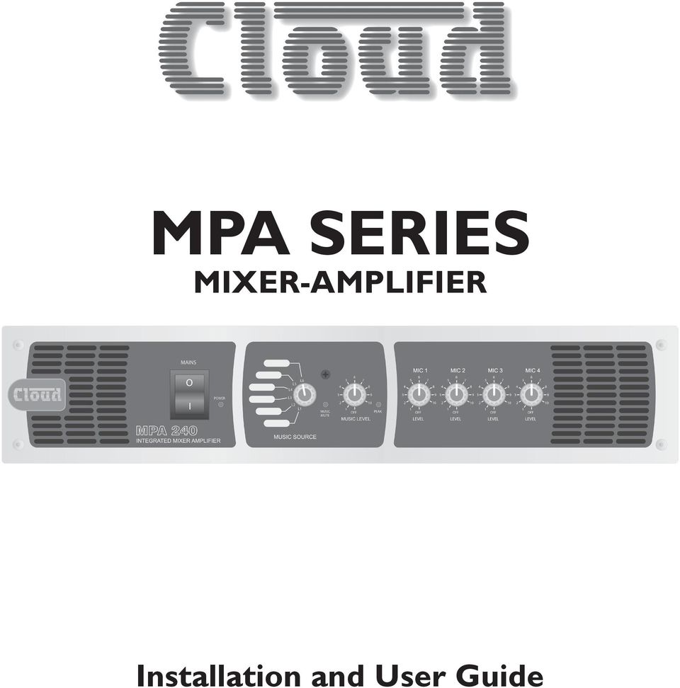
1 MPA SERIES MIXER-AMPLIFIER Installation and User Guide
2

3 Contents Safety Information... 4 Safety Notes regarding Installation...4 Conformities... 4 Safety Considerations and Information...4 Caution - High Voltages...4 Caution - Mains Fuse...4 Caution - Servicing...4 General Description... 5 Schematic Diagram... 5 General Notes Multi-zone Applications...11 EMC Considerations...11 Earthing...11 Ventilation...11 Technical Specifications Location of internal jumpers, etc Factory Default Jumper Settings...13 Front Panel Description... 6 Rear Panel Description... 6 Music Inputs... 7 Sensitivity & Gain Control...7 Music Source Select...7 Music Level Control...7 Remote Control of Music Source...7 Select and Level...7 Music Equalisation... 8 Music Priority... 8 Microphone Inputs... 8 Gain Control...8 Microphone Access Input...8 Front Panel Microphone Level Controls... 8 Microphone Equalisation... 8 Microphone Priority... 9 Microphone over music priority...9 Mic 1 over Mics 2-4 priority...9 Chime... 9 Power Amplifier Stage and Outputs... 9 Low impedance operation...9 Line Output...9 High pass filter...10 Music Mute(Fire Alarm Interface) Bose Equalisation Modules Installation Instructions...10 MPA Series User Manual v1.1 3

4 Safety Information Safety Notes regarding Installation Do not expose the unit to water or moisture. Do not expose the unit to naked flames. Do not block or restrict any air vent. Do not operate the unit in ambient temperatures above 35 O C. Do not touch any part or terminal carrying the hazardous live symbol ( ) while power is supplied to the unit. Do not perform any internal adjustments unless you are qualified to do so and fully understand the hazards associated with mains-operated equipment. The unit has no user-serviceable parts. Refer servicing to qualified service personnel. If the moulded plug is cut off the mains lead for any reason, the discarded plug is a potential hazard and should be disposed of in a responsible manner. For more detailed information refer to the rear of the manual. Safety Notes Conformities This product conforms to the following European EMC Standards: BS EN :1997 BS EN :1997 This product has been tested for use in commercial and light industrial environments. If the unit is used in controlled EMC environments, the urban outdoors, heavy industrial environments or close to railways, transmitters, overhead power lines, etc., the performance of the unit may be degraded. The product conforms to the following European electrical safety standard: BS EN 60065:2002 Safety Considerations and Information The unit must be earthed. Ensure that the mains power supply provides an effective earth connection using a threewire termination. When the mains switch is in the off O position the live and neutral conductors of the mains transformer are disconnected. Caution - High Voltages Do not touch any part or terminal carrying the hazardous live symbol ( ) while power is supplied to the unit. Terminals to which the hazardous live symbol refers require installation by a qualified person. Caution - Mains Fuse Replace the mains fuse only with the same type and rating as marked on the rear panel. The fuse body size is 20mm x 5mm. Caution - Servicing The unit contains no user serviceable parts. Refer servicing to qualified service personnel. Do not perform servicing unless you are qualified to do so. Disconnect the power cable from the unit before removing the top panel and do not make any internal adjustments with the unit switched on. Only reassemble the unit using bolts/screws identical to the original parts. The MPA Series was developed and manufactured with high quality materials and components, which can be recycled and/or reused. The WEEE symbol indicates that electrical and electronic equipment must be disposed of separately from normal waste at the end of its operational lifetime. Please dispose of this product by taking it to your local collection point or recycling centre. 4 MPA Series User Manual v1.1

5 General Description The Cloud MPA Series is a range of mixer-amplifiers with applications in Licensed, Retail, Leisure and similar venues. Three models are available to suit different output power requirements (60, 120 or 240 watts); otherwise all models have identical facilities. The mixer-amplifiers have inputs for six stereo line signals and four microphone signals. Front panel controls are provided for music source selection, music level and microphone levels. All pre-set controls are located on the rear panel with further configuration jumpers mounted on the main PCB. A remote level control or combined level control/music source selector can be wired to the unit for installations that require remote control. Schematic Diagram fig.1: MPA Series Schematic Diagram MPA Series User Manual v1.1 5

6 MAINS O I POWER L6 L5 L4 L3 L2 L1 MUSIC MUTE PEAK OFF OFF OFF OFF OFF LEVEL LEVEL LEVEL LEVEL fig.2: MPA Front Panel Front Panel Description MIC LEVEL 1 to 4 - level controls for Mic Inputs 1 to 4 2 MUSIC SOURCE selects active Line Input (1 to 6) 3 MUSIC LEVEL adjusts level of selected Line Input 4 PEAK illuminates if Mic or Line signals level are too high 5 MUSIC MUTE illuminates when external Emergency Mute is active 6 MAINS AC power switch with LED 7 Ventilation slots forced-air cooling air intake fig.3: MPA Rear Panel Rear Panel Description 1 LINE 1 to LINE 6 stereo line inputs for music sources 2 GAIN 1 to GAIN 6 level trims for each line input 3 MUSIC EQ LF and HF EQ adjustment for music channel 4 MIC 1 to MIC 4 balanced mic inputs 5 GAIN 1 to GAIN 4 level trims for each mic input 6 MIC EQ LF and HF EQ adjustment for mic channel 7 ACCESS external paging control input for Mic 1 8 LOW IMPEDANCE OUTPUT speaker output for low-z connection 9 LINE OUTPUT for connection of 100 V/ 70 V/25 V line distribution system 10 MUSIC MUTE Emergency control input for muting music source 11 REMOTE MUSIC CONTROL for connection of RL-1 or RSL-6 remote control panels 12 REMOTE/LOCAL disables front panel controls when remote control is in use 13 IEC mains input 14 Mains fuse 15 Fan forced-air cooling air exhaust 6 MPA Series User Manual v1.1

7 Music Inputs The unit has six stereo line inputs; these inputs are suitable for most music sources such as compact disc players, tape players, satellite receivers and the like. Each stereo input is summed internally to mono. All inputs are unbalanced and use RCA phono sockets. The input impedance is 47k ohm. Line 6 input can be configured to have priority over any other music source, see Music Priority, page 8. Sensitivity & Gain Control All six stereo line inputs have a preset gain control on the rear panel adjacent to the respective input sockets. The gain control has a range of 20 db allowing the input sensitivity to be varied from -12 dbu (200 mv) to +8 dbu (2.0 V). The preset gain control should be adjusted so that all the input signals are operating at the same level and that the front panel level control has an optimum range of control. Music Source Select This front panel six position switch is used to select the desired music signal. Remote control of source selection is possible with a remote control plate (RSL-6), See fig.4. Music Level Control A front panel mounted music level control is provided. Remote control of music level is possible by connecting a remote control plate (either RSL-6 or RL-1), See fig.4. Remote Control of Music Source Select and Level The MPA Series mixer-amplifiers are compatible with standard Cloud remote control plates Types RSL-6 (music source select and level) and RL-1 (level only). Either type of plate may be connected at the rear 3-pin 5 mm-pitch screw terminal connector (Remote Music Control), using the wiring shown in fig.4. Use two-core (RSL-6 or RL-1) or single-core (RL-1 only) screened cable to connect the remote level plate (max length 100 metres). Pressing the button adjacent to the rear panel connector activates the remote control plate and disables both the front panel level and source select controls. If an RL-1 is being used, the internal jumper J4 should be moved from its default SW setting to FR, to override the disabling of the front panel source select switch. See fig.7 for location of jumpers. REMOTE LEVEL CONTROL WIRING REMOTE SOURCE & LEVEL CONTROL WIRING RL-1 REMOTE MUSIC CONTROL CONNECTOR REMOTE MUSIC CONTROL CONNECTOR RSL SINGLE-CORE SCREENED CABLE MAY BE USED USE TWO-CORE SCREENED CABLE fig.4: RL-1 and RSL-6 Wiring MIC INPUTS PIN 1: SCREEN (GROUND) PIN 2: COLD/ANTIPHASE (-) PIN 3: HOT/PHASE (+) SCN + SCN BALANCED CONNECTION UNBALANCED CONNECTION fig.5: Microphone Input Wiring MPA Series User Manual v1.1 7

8 Music Equalisation One set of independent bass and treble controls is provided for the music signals. These preset controls are located on the rear panel below the line input sockets. The treble control has a range of ±10 db at 10 khz and the bass control has a range of ±10 db at 50 Hz. Music Priority A Juke Box, Digital Sound Store or other audio source can be given automatic priority over all other music inputs by connecting it to Line 6 input and moving internal jumpers 5A and 5B from the OFF position (factory default) to the ON. When this mode of operation is selected, the unit will operate normally until a signal is detected on Line 6, when the selected source (usually background music) is muted, allowing the source connected to Line 6 to replace it. Once the signal on line 6 stops, the selected source will smoothly restore to its former level. The time taken for the restoration is set in the factory at 3 seconds, but it may be set at 6 or 12 seconds with internal jumper J7. (3s is suitable for announcements, but the longer times may be more appropriate when a jukebox or similar is the Line 6 source.) See fig.7 for location of jumpers. Microphone Inputs Four microphone inputs are provided; the microphone preamplifiers are an electronically balanced, transformer-less design configured for optimum low noise performance. The input impedance is greater than 2 kω and is suitable for microphones in the 200 Ω to 600 Ω range. Inputs are via 3-pin 3.5 mm-pitch screw terminal connectors on the rear panel. Connect microphones as shown in fig.5. Note that if using an unbalanced microphone, pins 1 and 2 should be connected together. Phantom power is available on any or all of the mic inputs, and is activated by setting internal jumpers J9 to J12 (for mic inputs 1 to 4 respectively) to the ON position. See fig.7 for location of jumpers. Care should be taken to ensure that phantom power is activated only when the microphone connected to the input requires external phantom power; damage to the microphone may result otherwise. Gain Control A mic gain control (of the preset type) is provided adjacent to each input connector. The gain can be adjusted from 10 db to 50 db. A high overload margin is maintained at all gain settings. Microphone Access Input Mic input 1 is equipped with an external access control input; this is a 2-pin 5 mm-pitch screw terminal connector adjacent to the Mic input 1 connector. The access input is primarily intended to provide compatibility with paging microphones and their associated switching arrangements. By default, the access function is bypassed. To use the function, it must be enabled by moving internal jumper J13 from its default ON setting to OFF. See fig.7 for location of jumpers. Once enabled, the microphone input is muted while the pins of the access connector are opencircuit. When the pins are connected together, Mic input 1 becomes active for use. The access input can also trigger the following functions: Mic 1 Priority over Mics 2-4 Activation of Mic 1 via the access input will give Mic 1 priority over Mics 2, 3 and 4 if internal jumper J8 is set to ON. See fig.7 for location of jumpers. See also Mic 1 over Mics 2-4 priority, page 9. Chime The internal chime generator will be activated if internal jumper J1 is set to ON. See fig.7 for location of jumpers. See also Chime, page 9. Front Panel Microphone Level Controls A separate level control is provided for each mic input and these provide the user with a convenient means of adjusting the audio level of the microphones. The microphone signals are routed directly to the power stage and are unaffected by the operation of the music level control. The gain controls on the rear panel (see Gain Control) should be set at a level where microphone distortion does not occur even when the front panel level controls are fully clockwise. Microphone Equalisation The four microphone inputs are summed together and are routed to the power stage via a fixed high pass filter and an adjustable EQ section. The fixed filter attenuates the signal below 100 Hz, which helps to reduce the effects of microphone handling noise. The two preset EQ controls are on the rear panel adjacent to the mic inputs; the LF and HF controls provide ±10 db of adjustment below 100 Hz and above 5 khz respectively. After installation, some test announcements should be made, 8 MPA Series User Manual v1.1
 to the ON.")
9 ideally by the people who will normally make them. The Mic EQ should be adjusted if necessary to maximise voice clarity. Microphone Priority MPA Series mixer-amplifiers provide two separate microphone priority functions. One of these enables the microphones to have priority over music, the other allows Mic 1 to have priority over the other microphones. Power Amplifier Stage and Outputs Low impedance operation The MPA Series amplifiers are able to deliver their rated power into a 4 ohm load, as follows: Microphone over music priority Fully automatic voice operated priority (VOX function) is available for the microphone signals. This function is enabled by internal jumper J6 (default setting is ON). When enabled, the music signal is automatically attenuated by 30 db when a microphone signal is detected, allowing the message to be clearly heard. Normal music operation is restored smoothly after the announcement ends. Note that the presence of a signal on any of the four mic inputs will operate this function. Mic 1 over Mics 2-4 priority If internal jumper J8 is set to ON (the default setting is OFF), Mic inputs 2, 3 and 4 will be muted whenever the Microphone Access Input is enabled. This ensures that Mic 1 will always have priority over any other microphones in use when Mic 1 is used for paging. Note that if jumper J13 is left at its default setting of ON, Mics 2, 3 and 4 will be permanently disabled by this function, leaving Mic 1 as the only active microphone input. Chime The MPA Series amplifiers have an internal preannouncement chime generator. The chime is triggered by the Microphone Access Input, if enabled by jumper J1 being set to ON. J1 s default setting is OFF. An internal preset rotary control is provided to adjust the chime volume; the front panel level controls have no effect on the chime level. See fig.7 for locations of internal controls. Model MPA60 MPA120 MPA240 Rated Power 60 watts 120 watts 240 watts The maximum output power will be reduced with higher load impedances. When using multiple low-impedance loudspeakers (normally 8 ohms) with a single amplifier, series and/or parallel wiring should be employed to produce a total load impedance of not less than 4 ohms. The low impedance output is available on a 2-pin 5 mm-pitch screw terminal connector on the rear panel. Note that one of the output pins is connected internally to 0 V. Line Output MPA Series amplifiers are fitted as standard with an output transformer that can be enabled by moving an internal connector. The transformer should be placed in circuit if the amplifier is to be used with a 100 V, 70 V or 25 V line speaker distribution system. To convert the amplifier to high-voltage line operation, the low impedance output socket should be unplugged from CON8 on the main pcb (a short pair of heavy red and black wires), and replaced by the spare plug connected to the toroidal transformer nearer the rear of the unit (same wire types). Note that the low-impedance output will no longer be available once the transformer is plugged in. The secondary (output side) of the transformer is permanently wired to the line output connector (a 4-pin 5 mm-pitch screw terminal type), thus the high-voltage output will be active once the internal connector change has been made. A safety cover is fitted over the connector, which may be removed to connect the speaker cable. Replace the cover after the connection has been made. The transformer secondary has 3 line outputs: 100 V, 70 V and 25 V; whilst these have a common 0 V connection, the output is fully floating i.e. it is isolated from the rest of the amplifier. When the transformer is in use the maximum total combined load should not exceed the rated power for the amplifier model (see table above). MPA Series User Manual v1.1 9

10 When this transformer is in circuit it is strongly recommended that the amplifier s 65 Hz high pass filter is set ON (see section below: High pass filter). High pass filter A high pass filter is provided to protect speakers, transformers etc. from the effects of low frequency signals. The filter is enabled by the internal jumper J2 (see fig.7). The filter reduces the output level of frequencies below 65 Hz, and ideally should be used if the line output transformer is in circuit. Bose Equalisation Modules MPA Series amplifiers are compatible with single channel Bose Series II equalisation modules. EQ modules are available to suit the following Bose loudspeakers: Panaray MA12 Panaray 402-II, 502B and 502BEX Panaray LT Series: Models 3302, 4402, 9402 and Modules to suit other models are available please enquire. Music Mute (Fire Alarm Interface) In some installations (such as licensed premises or retail outlets within a shopping mall), there may be a local authority or fire service requirement to mute the music signals from a fire alarm control panel when an alarm condition arises. The MPA Series amplifiers include a facility to mute the music signals only (i.e., mic inputs are still active), via the Music Mute input. This is a 2-pin 5 mmpitch screw terminal connector on the rear panel, and the contacts are fully isolated. Activation of the Music Mute is often via a relay mounted close to the MPA Series amplifier, powered by the fire alarm control panel. Other arrangements may exist depending on the design of the fire control system and the fire alarm installation company should be consulted when making the connection. The MPA Series amplifiers will mute on either a contact closure at the Music Mute input (NO) or an opencircuit (NC). Selection of NO or NC operation is made with internal jumper J14. NO is the factory default. See fig.6. Installation Instructions Refer to the pcb layout diagram (see fig.7) for the location of the Bose EQ module connector and its associated bypass jumper J3. To install an EQ module, proceed as follows: Switch off the power and isolate the unit from the mains. Remove the top panel. Remove jumper J3 from the main pcb. Plug the Bose equalisation module onto its connector; note that the connector has two notches on one side which engage with lugs on the module s mating connector to ensure correct orientation. Replace the top panel. REMOTE MUSIC MUTE TERMINATIONS MUSIC MUTE INPUT 1 2 MUSIC MUTE INPUT 1 2 RELAY RELAY NORMALLY OPEN (NO) CONNECTION NORMALLY CLOSED (NC) CONNECTION fig.6: Remote Music Mute 10 MPA Series User Manual v1.1

11 General Notes Multi-zone Applications Where the sound system specification calls for separate control in several zones, MPA Series amplifiers can be used in multiples. Signal sources can be connected to several inputs as required, but care must be taken to ensure the output stage of the signal source is capable of driving the resulting lower input impedance. The impedance of the line inputs (music inputs) is 47k ohms and it is reasonable to assume that most op-amp based signal sources are able to drive a 10k ohm load, allowing up to five amplifiers to be paralleled. The input impedance of the mic inputs is 2.4k ohms, making them suitable for microphones with a nominal impedance of 600 ohms or less. A single 600 ohm microphone could therefore typically be connected to four paralleled mic inputs. If this guideline figure cannot be adhered to, the use of suitable mic or line distribution amplifiers is recommended. To avoid any problems associated with differences in mains supply earthing, we recommend that all MPA Series amplifiers used in a multi-zone application should be colocated and connected to a common mains supply. Note that when using multiple MPA Series amplifiers in a 19 rack, suitable ventilation arrangements must be made to ensure that lower amplifiers do not cause those above to overheat (see Ventilation for further information). EMC Considerations MPA Series amplifiers fully conform to the relevant electromagnetic compatibility (EMC) standards and are technically well behaved. You should experience no problems interfacing units to other items of equipment and under normal circumstances, no special precautions need to be taken. If the unit is to be used in close proximity to potential sources of HF disturbance such as high power communication transmitters, radar stations and the like, it is suggested that input signal leads be kept as short as possible. Always use balanced interconnections wherever possible. If the MPA Series amplifier is mounted in a 19 rack, do not locate the unit in close proximity to a powerful amplifier of any kind, which may radiate a strong magnetic field from the power transformer. Earthing When several mains powered units are connected together via their signal cables, there is a risk of one or more earth loops which may cause an audible hum on the system even with the gain controls set to minimum. The 0 V rail of an MPA Series amplifier is directly coupled to the chassis ground. No interconnection problems should be encountered, but if there is any hum or other extraneous noise when source equipment is connected, the situation can generally be remedied by observing the following guidelines: Always connect sources using balanced connections wherever possible, with the cable screen only connected at the receiving end (amplifier input). Use audio isolating transformers (readily available from trade suppliers) at the inputs if necessary. These will ensure that the amplifier is electrically isolated from the source equipment. The signal source units should be located as close as possible to the amplifiers and the metal housing of the various units should not be electrically connected together through the equipment rack. If this is a problem, rack isolating kits are available from specialist hardware suppliers. If the problem persists, try to connect all interconnected units, including power amplifiers to a common power source to ensure a common ground is provided. Ventilation MPA Series amplifiers are force cooled by a thermostaticallycontrolled fan. The fan is operative at all times, remaining at low speed at internal temperatures below 50 ºC, then increasing in speed above this temperature to a maximum speed at 70 ºC. Always allow adequate space around the amplifier(s) to allow a free flow of air through the unit(s). In 19 rack applications we recommend leaving 1U of rack space above and below each unit. Plain 1U blank panels, not slotted ventilation panels should be used, as the latter reduce the effect of forced-air cooling. The direction of airflow in MPA Series amplifiers is from front-to-rear; it is recommended not to mix the amplifiers with other equipment employing forced-air cooling which acts in the opposite direction within the same rack. In free standing applications we recommend fitting the feet supplied and placing the unit on a flat surface and leaving the ventilation slots on top of the unit free from any obstructions. MPA Series User Manual v1.1 11

12 Technical Specifications Line Inputs Frequency response Low-Z output +0 db/-1 db from 20 Hz 20 khz (65 Hz filter switched out) High voltage outputs +0 db/-2 db from 20 Hz 20 khz (65 Hz filter switched out) Distortion Low-Z output 1 khz, 1 db below full power (80 khz bandwidth) High voltage outputs 1 khz, 1 db below full power (80 khz bandwidth) Sensitivity 195 mv (-12 dbu) to 2.0 V (+8 dbu) Input Gain control 20 db range Input impedance 47k ohms Headroom >20 db Noise -90 db 22 Hz 22 khz, at speaker output, relative to full power Equalisation HF: ±10 db/10 khz LF: ±10 db/50 Hz Microphone Inputs Frequency response Low-Z output Hz (3 rd. order filter); -1 khz High voltage output Hz (3 rd. order filter); -2 khz Distortion 1 khz, 1 db below full power (80 khz bandwidth) Gain range 40 db range Input Impedance >2k ohms (balanced) Phantom Power 15 v, switchable per-input by jumpers Headroom >20 db Noise -127 db EIN 22 Hz-22 khz (150 ohms) Equalisation HF: ±10 db/5 khz LF: ±10 db/100 Hz Outputs Output Power* (any output, 1kHz continuous sine <0.07% THD+N) Protection Cooling MPA60 60 watts MPA watts MPA watts Fixed level signal limiter max gain reduction of 20 db, DC protection, IV limiting & short circuit protection, switch-on delay Forced-air, front-to-rear airflow, thermostatically controlled * see also Low impedance operation, page 9. General Specifications Power input 230 V, 115 V, 100 V versions available MPA V T1A H 115/100 V T2A H Fuse rating MPA V T2A H 115/100 V T4A H MPA V T4A H 115/100 V T6.3A H Fuse type All models 20 mm x 5 mm Dimensions (mm) wide x 88 high (2U) x 300 deep (+ connectors & knobs) MPA Net weight (kg) MPA MPA MPA Series User Manual v1.1
 Input Gain control 20 db range Input impedance 47k ohms Headroom >20 db Noise -90 db 22 Hz 22 khz, at speaker output, relative to full power Equalisation HF: ±10 db/10 khz LF: ±10 db/50")
13 Location of internal jumpers, etc. J2 J1 MPA SERIES: MAIN PCB. TOP VIEW. ONLY PRIMARY COMPONENTS SHOWN. J3 BOSE EQ CARD SOCKET J4 CHIME VOLUME CONTROL J6 J7 CON8 J8 FAN J9 J10 J5A & J5B J12 REAR OF AMPLIFIER NOT TO SCALE J13 (under sub-board) J11 (below ribbon cable) J14 fig.7: Internal jumpers Factory Default Jumper Settings Jumper Function Default Setting J1 Mic 1 access triggers chime OFF J2 65 Hz high pass filter frequency ON J3 EQ card socket bypass ON J4 Front panel source select switch disable SW J5 (A & B) Line input 6 priority OFF J6 Mic over music priority (VOX function) ON J7 Line 6 priority release time 3, 6 or 12 seconds 3s J8 Mic 1 priority over Mics 2, 3 & 4 OFF J9 Mic 1 phantom power OFF J10 Mic 2 phantom power OFF J11 Mic 3 phantom power OFF J12 Mic 4 phantom power OFF J13 Mic 1 Access Input bypass ON J14 Music Mute NO or NC NO MPA Series User Manual v1.1 13
 Line input 6 priority OFF J6 Mic over music priority (VOX function) ON J7 Line 6 priority release time 3, 6 or 12 seconds 3s J8 Mic 1 priority over")
14 Bose is a registered trademark of The Bose Corporation. In the interest of continuing improvements Cloud Electronics Limited reserves the right to alter specifications without prior notice. 14 MPA Series User Manual v1.1

15

16 Cloud Electronics Limited 140 Staniforth Road Sheffield S9 3HF England Tel: +44 (0) Fax: +44 (0) web:

How To Use A Pump Station 16-R
 Pump Station 16-R Installation & User Guide V2.1 Cloud Electronics Limited 140 Staniforth Road, Sheffield, S9 3HF England Tel +44 (0) 114 244 7051 Fax +44 (0) 114 242 5462 E-mail [email protected] Web site
ZMR 80 STEREO MODULAR ZONER USERS MANUAL
 ZMR 80 STEREO MODULAR ZONER USERS MANUAL Lime Technologies http://limetechnologies.co.uk Tel: 08712 233127 ZMR80 Stereo Modular Zoner Mixer Introduction The modular construction of the ZMR80 allows it
CX Zoner Installation & User Guide
 CX Zoner Installation & User Guide Cloud Electronics Limited 140 Staniforth Road, Sheffield, S9 3HF England Tel +44 (0)114 244 7051 Fax +44 (0)114 242 5462 e-mail [email protected] web site http://www.cloud.co.uk
IMPORTANT SAFETY INSTRUCTIONS
 IMPORTANT SAFETY INSTRUCTIONS When using this electronic device, basic precautions should always be taken, including the following: 1. Read all instructions before using the product. 2. Do not use this
PS 29M DUAL CHANNEL BELTPACK IN METAL CASE
 PS 29M DUAL CHANNEL BELTPACK IN METAL CASE USER MANUAL October 2013 This product is designed and manufactured by: ASL Intercom BV Zonnebaan 42 3542 EG Utrecht The Netherlands Phone: +31 (0)30 2411901 Fax:
LOXONE 12 Channel Amplifier
 LOXONE 12 Channel Amplifier Item no.: 200110 Thank you for purchasing the Loxone Twelve Channel Amplifier. The versatility of the Amplifier makes it the perfect choice for almost every type of custom multi-room
1 All safety instructions, warnings and operating instructions must be read first.
 ONYX USER MANUAL 2 Dateq ONYX Manual Safety instructions EN Safety instructions 1 All safety instructions, warnings and operating instructions must be read first. 2 All warnings on the equipment must be
Zone Mixer. 6 channels configurable from 24 inputs. 3 zone outputs. Expandable via Sys-Link TM Built-in comp/limiter, ducking and alarm functions
 GR 1 Zone Mixer W H E N Y O U R E M I X I N G W I T H P R O F E S S I O N A L S 6 channels configurable from 24 inputs. 3 zone outputs. Expandable via Sys-Link TM Built-in comp/limiter, ducking and alarm
STEREO PREAMPLIFIER INSTRUCTIONS FOR USE
 XX STEREO PREAMPLIFIER INSTRUCTIONS FOR USE Thank you for purchasing the Musical Fidelity A5 CR Preamplifier. Used properly and carefully, it should give many years of outstanding musical reproduction.
Active Speaker System LX523 AUDAC PROFESSIONAL AUDIO EQUIPMENT. Active Speaker System with remote input LX523. User Manual & Installation Guide
 Active Speaker System LX523 AUDAC PROFESSIONAL AUDIO EQUIPMENT Active Speaker System with remote input LX523 User Manual & Installation Guide AUDAC PROFESSIONAL AUDIO EQUIPMENT User Manual & Installation
************* OWNER'S MANUAL BAMF800/2 BAMF1250/2 BAMF1800/2 BAMF2200/2 BAMF2600/2 BAMF1200/4 BAMF1600/4 BAMF2000/1D BAMF4000/1D BAMF5500/1D
 ************* OWNER'S MANUAL BAMF800/2 BAMF1250/2 BAMF1800/2 BAMF2200/2 BAMF2600/2 BAMF1200/4 BAMF1600/4 BAMF2000/1D BAMF4000/1D BAMF5500/1D INTRODUCTION Power Acoustik amplifiers provide high-performance
Contents. Safety Warnings... 1
 Contents Safety Warnings... 1 Unpacking the GQ600... 1 Introduction... 2 GQ600 Filter Characteristics... 2 1/3 Octave Centre Frequencies... 4 Front Panel Functions... 5 Rear Panel Functions... 6 Specifications...
CV-5000 HEAVY DUTY PROFESSIONAL AMPLIFIER
 CV-5000 HEAVY DUTY PROFESSIONAL AMPLIFIER USER MANUAL IMPORTANT SAFETY INSTRUCTIONS 2 TABLE OF CONTENTS Introduction... 4 Features.. 5 Front Panel Controls.... 6 Rear Panel Controls. 8 Protection.... 10
TOA 900 SERIES II MIXER POWER AMPLIFIER
 Operating Instructions TOA 900 SERIES II MIXER POWER AMPLIFIER A-903MK2 A-906MK2 A-912MK2 TO REDUCE THE RISK OF ELECTRICAL SHOCK, DO NOT REMOVE COVER. NO USER SERVICEABLE PARTS INSIDE. REFER SERVICING
CMP30. User Manual. www.audac.eu
 CMP30 User Manual www.audac.eu 2 Index Introduction 4 Precautions 5 Safety requirements 5 Caution servicing 5 EC Declaration of Conformity 5 Waste of Electrical and Electronic Equipment (WEEE) 6 Caution
Features, Benefits, and Operation
 Features, Benefits, and Operation 2014 Decibel Eleven Contents Introduction... 2 Features... 2 Rear Panel... 3 Connections... 3 Power... 3 MIDI... 3 Pedal Loops... 4 Example Connection Diagrams... 5,6
Smarthome SELECT Bluetooth Wireless Stereo Audio Receiver and Amplifier INTRODUCTION
 Smarthome SELECT Bluetooth Wireless Stereo Audio Receiver and Amplifier INTRODUCTION The Smarthome SELECT Bluetooth Wireless Stereo Audio Receiver and Amplifier is a multi-functional compact device. It
5 CHANNEL MIXER. S Class Signal Processors
 0 10 0 10 0 10 0 10 5 CHANNEL MIXER S Class Signal Processors Table Of Contents Introduction and Features 3 Front and Rear Panel Layout 4 Operating the S mix Setting up the S mix 5 Connecting the Input
User Guide FFFA001106. www.focusrite.com
 User Guide FFFA001106 www.focusrite.com TABLE OF CONTENTS OVERVIEW.... 3 Introduction...3 Features.................................................................... 3 Box Contents...3 System Requirements....4
How To Use The Gr8A Power Amplifier
 GR8A 8 Channel Amplifier USER GUIDE Publication AP4298 Limited One Year Warranty This product has been manufactured in the UK by ALLEN & HEATH and is warranted to be free from defects in materials or workmanship
F(t) Forssell Technologies Inc
 Forssell Technologies Inc") F(t) Forssell Technologies Inc SMP-2Aa Microphone Preamplifier User Manual Forssell Technologies Inc Sandpoint Idaho USA (208) 263-0286 Introduction The Forssell Technologies Inc SMP-2A is a 2 channel,
F(t) Forssell Technologies Inc SMP-2Aa Microphone Preamplifier User Manual Forssell Technologies Inc Sandpoint Idaho USA (208) 263-0286 Introduction The Forssell Technologies Inc SMP-2A is a 2 channel,
user guide Meridian 558 Multi Channel Power Amplifier
 user guide Meridian 558 Multi Channel Power Amplifier Meridian 558 Multi Channel Power Amplifier User Guide ipreface Sales and service in the UK Meridian Audio Ltd Stonehill Stukeley Meadows Cambs PE18
ELAN AUDIO. Operational Description. News Work Station NWS-01
 ELAN AUDIO 2 STEEL COURT SOUTH GUILDFORD WA 6055 PHONE (08) 9277 3500 FAX (08) 9478 2266 email [email protected] web www.elan.com.au Operational Description. News Work Station NWS-01 The NWS-01 News
MPA-101. WARNING: Improper installation could result in damage to the amplifier and/or speakers. Read all instructions before installation.
 MPA-101 WARNING: Improper installation could result in damage to the amplifier and/or speakers. Read all instructions before installation. The lightning flash with arrowhead, within an equilateral triangle,
Digital FM/AM Receiver
 Digital FM/AM Receiver Model RM-350D User s Guide 54-5021-01 9609 Printed in USA Specifications Band Coverage............ AM.....................530-1620KHz FM......................87.5-107.9MHz Tuning....................PLL
TS510 & TS500. Installation & User Guide. Compatible Equipment
 Installation & User Guide Compatible Equipment TS510 REM - Remote Keypad 9040 - Loudspeaker DC54/58 - Digital Communicator SD1+ - Speech Dialler 496525 Issue A 1 of 10 TS510 and TS500 Overview Introduction
Achat 115MA full-range speaker. user manual
 Achat 115MA full-range speaker user manual Musikhaus Thomann Thomann GmbH Hans-Thomann-Straße 1 96138 Burgebrach Germany Telephone: +49 (0) 9546 9223-0 E-mail: [email protected] Internet: www.thomann.de
MODEL 2202IQ (1991-MSRP $549.00)
") F O R T H E L O V E O F M U S I C F O R T H E L O V E O F M U S I C MODEL 2202IQ (1991-MSRP $549.00) OWNER'S MANUAL AND INSTALLATION GUIDE INTRODUCTION Congratulations on your decision to purchase a LINEAR
F O R T H E L O V E O F M U S I C F O R T H E L O V E O F M U S I C MODEL 2202IQ (1991-MSRP $549.00) OWNER'S MANUAL AND INSTALLATION GUIDE INTRODUCTION Congratulations on your decision to purchase a LINEAR
W O R L D C L A S S H I F I
 W O R L D C L A S S H I F I O W N E R S M A N U A L Accessories: NAPSC, i-supply, Headline, Stageline IMPORTANT In order to comply with current European safety regulations it is essential that the Naim
Tone Hammer 500. Owners Manual. Manual Version 1.0
 Tone Hammer 500 Owners Manual Manual Version 1.0 1. Incorporating the preamp from the popular Tone Hammer preamp/di pedal this superlight bass head combines three bands of flexible EQ, a colorful "Drive"
Kit 106. 50 Watt Audio Amplifier
 Kit 106 50 Watt Audio Amplifier T his kit is based on an amazing IC amplifier module from ST Electronics, the TDA7294 It is intended for use as a high quality audio class AB amplifier in hi-fi applications
Owner s Manual AWM910 JENSEN AWM910 COMPACT DISC PLAYER RADIO CD COMPACT MUSIC SYSTEM MUTE AUX BAND AUX IN PUSH PUSH PWR VOL ALARM T/F AUD SPK A SPK B
 AWM910 Owner s Manual COMPACT DISC PLAYER PUSH 1 2 3 4 5 6 RPT SCAN RDM H M PUSH PWR VOL ALARM SET ON/OFF EQ T/F AUD RADIO CD COMPACT MUSIC SYSTEM MUTE AUX BAND CD AUX IN A B A+B JENSEN AWM910 Thank You!
TELIKOU Intercom System. MS-500(4+1 channel) Main Station Instruction Manual
 Main Station Instruction Manual") TELIKOU Intercom System MS-500(4+1 channel) Main Station Instruction Manual TELIKOU Systems All Rights Reserved While TELIKOU makes every attempt to maintain the accuracy of the information contained in
TELIKOU Intercom System MS-500(4+1 channel) Main Station Instruction Manual TELIKOU Systems All Rights Reserved While TELIKOU makes every attempt to maintain the accuracy of the information contained in
INSTRUCTIONS FOR USE Pro-Ject Tube Box S
 INSTRUCTIS FOR USE Pro-Ject Tube Box S Dear music lover, thank you for purchasing a PRO-JECT AUDIO phono amplifier. In order to achieve maximum performance and reliability you should study these instructions
Operation Manual for Users
 Operation Manual for Users Model No.: FLTAMFMRCD!!!!!!!!!! ATTENTION!!!!!!!!!! THE RESET BUTTON MUST BE PRESSED TO ENSURE PROPER OPERATION. SEE INSTRUCTION MANUAL Table of Contents Table of Contents ---------------------------------------------------------------------------------------------
EN54-16 Voice Alarm System PRODUCT DATASHEETS
 EN54-16 Voice Alarm System PRODUCT DATASHEETS WayGuard This page is intentionally left blank Pagina 2 di 16 WayGuard Revision history Rel. Data Autore Modifiche 1.00 25/02/15 First emission Pagina 3 di
ST Series POWER SUPPLIES USER INSTRUCTIONS
 Introduction These instructions detail the installation and operation requirements for the ST20 & ST35 power supplies. These have been designed for operation in RV s providing a DC power system, with optional
Daker DK 1, 2, 3 kva. Manuel d installation Installation manual. Part. LE05334AC-07/13-01 GF
 Daker DK 1, 2, 3 kva Manuel d installation Installation manual Part. LE05334AC-07/13-01 GF Daker DK 1, 2, 3 kva Index 1 Introduction 24 2 Conditions of use 24 3 LCD Panel 25 4 Installation 28 5 UPS communicator
ELECTRICAL AUDIO EApreq
 ELECTRICAL AUDIO EApreq (Preliminary Info) The EAPreq is a two channel transformer-based microphone preamp/equalizer. The preamp is designed to allow the character of the input transformer to color the
eela-audio EA916 Journalist Unit USB Audio module with Telephone Hybrid User manual
 eela-audio EA916 Journalist Unit USB Audio module with Telephone Hybrid User manual EA Broadcast / Eela Audio, Het Riet 8 A, 5431NM Cuijk, The Netherlands http://www.eela-audio.com e-mail: [email protected]
Drayton Digistat +2RF/+3RF
 /+3RF Programmable Room Thermostat Wireless Model: RF700/22090 Model: RF701/22092 Power Supply: Battery - Thermostat Mains - Digistat SCR Invensys Controls Europe Customer Service Tel: 0845 130 5522 Customer
Brio-Rmanual:Cursamanual.qxd 08/04/2011 09:25 Page1
 - Brio-Rmanual:Cursamanual.qxd 08/04/2011 09:25 Page1 Brio-Rmanual:Cursamanual.qxd 08/04/2011 09:25 Page2 CONTENTS INTRODUCTION, FEATURES AND TECHNOLOGY 1-3 INSTALLATION 3 CONNECTIVITY 4-6 LOUDSPEAKER
MA-4150 ORDERCODE D6149 Highlite International B.V.
 MA-4150 ORDERCODE D6149 Highlite International B.V. Vestastraat 2 6468 EX Kerkrade The Netherlands Congratulations! You have bought a great, innovative product from DAP Audio. The DAP Audio MA-4150 brings
CDPM Setup and Installation Guide
 Clearly Better Sound Version 1 CDPM DIGITAL PAGING MICROPHONE Cloud Electronics Limited CDPM Setup and Installation Guide Copyright Cloud Electronics Limited 2005 CDPM Setup and Installation Guide Cloud
KEYBOARD EXTENDED RANGE. Sixty Owner, s Manual P/N 049254
 THE SOUND THAT CREATES LEGENDS KEYBOARD EXTENDED RANGE Sixty Owner, s Manual P/N 049254 INTRODUCTION Your new Fender KXR 60 Keyboard Amplifier is the result of Fender s ongoing dialog with many of today
M Zero. Owner's Information. Music's Finest Conductor. Level 0 line pre-amplifier
 M Zero Level 0 line pre-amplifier Owner's Information Music's Finest Conductor Introduction to the M Zero pre-amplifier Congratulations on your purchase of the Audio Note M Zero level 0 pre-amplifier.
R S E R I E S M I X E R S R - 2 0 0 R - 1 6 0 4 R - 2 0 0 4
 R SERIES MIXERS R-200 R-1604 R-2004 THE R SERIES MIXERS The R Series of mixers from Wharfedale Professional are designed to offer a superior quality audio performance in an easy to use, great value package.
DAB+ / FM Tuner Model: TU-201
 DAB+ / FM Tuner Model: TU-201 Instruction Manual www.pulse-audio.co.uk 1 Safety Information The lightning bolt within a triangle is intended to alert the user to the presence of dangerous voltage levels
To reduce the risk of electrical shocks, fire, and related hazards:
 Owner s Manual 1 Contents 1. Safety Notes 5 2. Introduction 6 3. Features 7 4. Installation Guide 8 5. Front Panel Explained 9 6. Rear Panel Explained 10 7. Software Control Panel 12 8. Advanced User Tips
OWNER'S MANUAL. AtlasSound.com PA601 COMMERCIAL AMPLIFIER. PA601 Commercial Amplifier. Power. Master
 Signal Peak Power Power On Off Master PA601 Commercial Amplifier TABLE OF CONTENTS Safety Instructions.....2 Introduction, Features, and Applications......3 Safety Precautions.........4 Front Panel Description......6
THE MclNTOSH MC 2100 SOLID STATE STEREO POWER AMPLIFIER
 THE MclNTOSH MC 2100 SOLID STATE STEREO POWER AMPLIFIER Price $1.25 Your MC 2100 stereo amplifier will give you many years of pleasant and satisfactory performance. If you have any questions concerning
QUALITY AV PRODUCTS INMATE/INMATE USB PROFESSIONAL 19" MIXER. User Guide and Reference Manual
 INMATE/INMATE USB PROFESSIONAL " MIXER User Guide and Reference Manual INTRODUCTION Welcome to the NEWHANK INMATE and INMATE USB professional " mixers series user manual. INMATE and INMATE USB both offer
Perseus. Owner s Manual. Vacuum Tube Preamplifier. Rogue Audio, Inc. 3 Marian Lane Brodheadsville, PA 18322. Issue date: 02/01/06
 Perseus Vacuum Tube Preamplifier Owner s Manual Rogue Audio, Inc. 3 Marian Lane Brodheadsville, PA 18322 Issue date: 02/01/06 TABLE OF CONTENTS 1) Introduction 2 2) Unpacking the Perseus Preamplifier 2
Plena Loop Amplifier. Installation and User Instructions PLN-1LA10
 Plena Amplifier en Installation and User Instructions PLN-LA Plena Amplifier Installation and User Instructions Important safeguards en 3 Important safeguards Before you install or operate the Plena Amplifier,
CINEMA SB100 powered soundbar speaker
 CINEMA SB100 powered soundbar speaker quick-start guide Thank You For Choosing This JBL Product The JBL Cinema SB100 powered soundbar speaker is a complete, integrated sound system that will dramatically
IRT Eurocard. Type DAX-3206. Audio Extractor for 270 Mb/s SDI
 I R T Electronics Pty Ltd A.B.N. 35 000 832 575 26 Hotham Parade, ARTARMON N.S.W. 2064 AUSTRALIA National: Phone: (02) 9439 3744 Fax: (02) 9439 7439 International: 61 2 9439 3744 61 2 9439 7439 Email:
Focusrite Saffire 6 USB. User Guide
 Focusrite Saffire 6 USB User Guide 1 IMPORTANT SAFETY INSTRUCTIONS 1. Read these instructions. 2. Keep these instructions. 3. Heed all warnings. 4. Follow all instructions. 5. Do not use this apparatus
MANUAL ENGLISH Mini-GIG Order code: D2280
 MANUAL ENGLISH Mini-GIG Highlite International B.V. Vestastraat 2 6468 EX Kerkrade the Netherlands Table of contents Warning... 2 Unpacking Instructions... 2 Safety Instructions... 2 Operating Determinations...
Controls (front) 1. Loudspeaker 2. Light button 3. Band button 4. Auto tune button 5. Alarm button 6. LCD display
 1. Loudspeaker 2. Light button 3. Band button 4. Auto tune button 5. Alarm button 6. LCD display") GB Contents Controls... 2-4 Mains operation... 5 Operating your radio... 6 Selecting a station DAB... 7 Display modes DAB... 8 Finding new stations - DAB... 9 Secondary services DAB... 9 Manual tuning
GB Contents Controls... 2-4 Mains operation... 5 Operating your radio... 6 Selecting a station DAB... 7 Display modes DAB... 8 Finding new stations - DAB... 9 Secondary services DAB... 9 Manual tuning
OWNER'S MANUAL HIGH PERFORMANCE AMPLIFIERS
 OWNER'S MANUAL HIGH PERFORMANCE AMPLIFIERS B2 has through years of dedication introduced our line of Ref 0.5 & Anno amplifiers. The B2 line up are made to fullfil our philosophy for amplifiers; A variety
MODEL 5010 DUAL CHANNEL SMOKE/FIRE DETECTION MODULE
 DESCRIPTION MODEL 5010 DUAL CHANNEL SMOKE/FIRE DETECTION MODULE DESCRIPTION The SST Model 5010 Two Channel Smoke/Fire Detection Module provides two independent detection input channels for the NOVA-5000
TELIKOU Intercom System. TM-200 Main Station. Instruction Manual
 Intercom System TM-200 Main Station Instruction Manual TELIKOU Systems All Rights Reserved I. Introduction Thank you for choosing TELIKOU intercom product. TM-200 main station is suitable for television
Hegel H1 High End Integrated Amplifier
 Hegel H1 High End Integrated Amplifier www.hegel.com [email protected] USER GUIDE Congratulations on your new HEGEL! Our products are based on a simple philosophy: The component shall reproduce the original
Congratulations! Thank you!
 TM-47 ORDERCODE D1370 Congratulations! You have bought a great, innovative product from DAP Audio. The DAP Audio Microphone range brings excitement to any venue. Whether you want simple plug-&-play action
Active Monitor Box McCrypt S.T.E.V.E. 15. Order No. 30 17 06
 Active Monitor Box McCrypt S.T.E.V.E. 15 Order No. 30 17 06 1 McCrypt Active Monitor 15 Introduction Dear Customer, Thank you for purchasing this McCrypt Active Monitor. You have chosen a quality product
Universal Host. Desktop Digital Hybrid. User Guide. JK Audio
 Universal Host Desktop Digital Hybrid User Guide JK Audio Introduction Universal Host will allow you to send and receive audio through your multi-line PBX, ISDN, VoIP or analog telephone. While this may
BXR. Owner, s Manual. One hundred BASS EXTENDED RANGE P/N 040695
 THE SOUND THAT CREATES LEGENDS BASS EXTENDED RANGE BXR One hundred Owner, s Manual P/N 040695 BXR 100 Owner s Manual Congratulations on your purchase of the Fender BXR 100 Bass amplifier. The Fender BXR
Gemini II. Subwoofer System OWNERS MANUAL
 Gemini II Subwoofer System OWNERS MANUAL CONTENTS Page No. 1) Safety instructions. 2) 3) 4) Connecting up your Gemini II. Connecting up using the high level input. Connecting up using the low level input.
INTRODUCTION. Please read this manual carefully for a through explanation of the Decimator ProRackG and its functions.
 INTRODUCTION The Decimator ProRackG guitar noise reduction system defines a new standard for excellence in real time noise reduction performance. The Decimator ProRackG was designed to provide the maximum
MAC 2.2/2.3/2.4 PROFESSIONAL STEREO AMPLIFIERS
 MAC././.4 PROFESSIAL STEREO AMPLIFIERS OWNER'S MANUAL www.altoproaudio.com Version. NOV 007 English IMPORTANT SAFETY INSTRUCTI CAUTI RISK OF ELECTRIC SHOCK DO NOT OPEN TO REDUCE THE RISK OF ELECTRIC SHOCK
OPERATING MANUAL PUBLIC ADDRESS POWER AMPLIFIER PA-9336
 OPERATING MANUAL PUBLIC ADDRESS POWER AMPLIFIER PA-9336 1 UNPACKING AND INSTALLATION Although it is neither complicated to install nor difficult to operate your PA amplifier, a few minutes of your time
SYSTEM 4C. C R H Electronics Design
 SYSTEM 4C C R H Electronics Design SYSTEM 4C All in one modular 4 axis CNC drive board By C R Harding Specifications Main PCB & Input PCB Available with up to 4 Axis X, Y, Z, A outputs. Independent 25
Praesideo - Digital Public Address and Emergency Sound System
 Praesideo - Digital Public Address and Emergency Sound System Praesideo - Digital Public Address and Emergency Sound System 2 Praesideo - Digital Public Address and Emergency Sound System Praesideo - Digital
Contents. Mission Statement...2. Warnings... 4. Wire Size...5. Installation Guidelines... 6. i-force Inputs...9. Bass Boost Control...10. i-force...
 Contents Mission Statement...2 Warnings... 4 Wire Size...5 Installation Guidelines... 6 i-force Inputs...9 Bass Boost Control...10 i-force...11 i-250...11 i-2100...14 i-450...17 i-4100...20 i-5100...23
BXR 300C BXR 300R. Owner, s Manual P/N 040294
 THE SOUND THAT CREATES LEGENDS BXR 300C BXR 300R Owner, s Manual P/N 040294 INTRODUCTION The Fender BXR 300 AMPLIFIER is the most recent effort in state of the art bass amplifier technology, and is a member
USA 305. Power Amplifier OWNERS MANUAL AND INSTALLATION GUIDE PARALLEL/SERIES WIRING DIAGRAMS. two 4 ohm woofers in parallel = 2 ohms
 PARALLEL/SERIES WIRING DIAGRAMS USA 305 two 4 ohm woofers in parallel = 2 ohms two 4 ohm woofers in series = 8 ohms SOUNDSTREAM TECHNOLOGIES 120 Blue Ravine Road Folsom California 95630 USA ph 916.351.1288
TUBE-TECH HLT 2A Stereo High- and Low shelving, T- filter & Low- and High cut
 TUBE-TECH HLT 2A Stereo High- and Low shelving, T- filter & Low- and High cut Description: The TUBE-TECH HLT 2A is a stereo unit, featuring low and high cut filters, low and high shelving filters and a
CDI-S100 SERIAL INTERFACE CARD
 CDI-S100 SERIAL INTERFACE CARD R R SERIAL INTERFACE MODULE MUSIC MUTE L L GAIN 0 LINE 5 LINE 6 db -10 + 10 MIC LEFT RIGHT FUSE 230V RATING 115V T100mA T200mA POW Installation Guide 2 CDI-S100 Installation
PERSONAL MONITOR MIXER/HEADPHONE AMP. S Class Signal Processors
 PERSONAL MONITOR MIXER/HEADPHONE AMP S Class Signal Processors Table Of Contents Features 3 Front and Rear Panel Layout 4 Operating the S monitor 5-7 Specifications 8 Wiring Guide 8 Copyright 2003, Samson
EVC40 EMERGENCY VOICE COMMUNICATION SYSTEM
 EVC40 EMERGENCY VOICE COMMUNICATION SYSTEM INSTALLATION MANUAL Protec Fire Detection PLC, Protec House, Churchill Way, Nelson, Lancashire, BB9 6RT. Telephone: +44 (0) 1282 717171 Fax: +44 (0) 1282 717273
VIEW. SLX300 SpeakerLinX IP Zone. Amplifier Installation and Setup Guide. AVoIP
 VIEW SLX300 SpeakerLinX IP Zone Amplifier Installation and Setup Guide TM AVoIP ClearOne 5225 Wiley Post Way Suite 500 Salt Lake City, UT 84116 Telephone 1.800.283.5936 1.801.974.3760 Tech Sales 1.800.705.2103
CELO5. User & Installation Manual. www.audac.eu
 CELO5 User & Installation Manual www.audac.eu 2 Introduction 5 High-end Slim Ceiling Speaker The CELO5 is the 5 version of AUDAC s CELO High-end Slim ceiling speaker series with an RMS power of 50 Watt
Hear The Future...Now! SIEM-2T/SIEM-2R
 Hear The Future...Now! SIEM-2T/SIEM-2R UHF PLL Mono In Ear Monitoring System 856 59508-03 ATTENTION Please pay high attention to the following information. The guideline published by Occupational Safety
Plena Two-zone Call Station. Installation and User Instructions PLE-2CS
 Plena Two-zone Call Station en Installation and User Instructions PLE-2CS Plena Two-zone Call Station Installation and User Instructions Important safeguards en 2 Important safeguards Before installing
LT-82 Stationary IR Transmitter
 LT-82 Stationary IR Transmitter Configuration LT-82-0 (North America) LT-82-02 (Asia, UK) LT-82-03 (Euro) The Listen LT-82 is the heart of a stationary IR listening system. It takes the desired audio signal
Plena Voice Alarm System. Installation and Operation manual
 Plena Voice Alarm System. en Installation and Operation manual Plena Voice Alarm System Table of Contents en 3 Table of Contents 1 Safety 9 1.1 Important Safeguards 9 1.2 Important Notices 9 2 About this
POWERED MIXERS. From Fender Pro Audio. Owner's Manual for SRM 6302 / 8302 P/N 050804 REV A
 POWERED MIXERS From Fender Pro Audio 6 3 0 2 / 8 3 0 2 Owner's Manual for SRM 6302 / 8302 P/N 050804 REV A Fender Musical Instruments 7975 North Hayden Road, Scottsdale, Arizona 85258 U.S.A. Fender knows
AMU PROFESSIONAL VIDEO AND AUDIO MONITORING UNIT OPERATOR'S HANDBOOK ISSUE A3
 AMU PROFESSIONAL VIDEO AND AUDIO MONITORING UNIT OPERATOR'S HANDBOOK ISSUE A3 2008 Hamlet Video International Ltd. All rights reserved This handbook contains proprietary information of Hamlet Video International
Plena Voice Alarm System. Software Manual Configuration Software
 Plena Voice Alarm System en Software Manual Configuration Software Plena Voice Alarm System Software Manual Table of Contents en 3 Table of Contents Table of Contents...3 1. Introduction...7 1.1 Purpose...7
EVID Compact Sound Speaker System
 EVID Compact Sound Speaker System EVID-C44, EVID-C2.1, EVID-40C, EVID-S44, EVID-S44W, EVID-2.1, EVID-2.1W, EVID-40S, and EVID-40SW en Installation Manual en 3 Table of contents 1 Safety 4 2 Welcome 6
MANUAL ENGLISH Clubmate II Ordercode: D3264
 MANUAL ENGLISH Clubmate II Highlite International B.V. Vestastraat 2 6468 EX Kerkrade the Netherlands Table of contents Warning... 2 Unpacking Instructions... 2 Safety Instructions... 2 Operating Determinations...
MCA Series Multi-Channel Amplifiers. Operation Manual
 MCA Series Multi-Channel Amplifiers Operation Manual February 2012 Biamp Systems, 9300 SW Gemini Drive, Beaverton, Oregon 97008 U.S.A. (503) 641-7287 www.biamp.com IMPORTANT SAFETY INSTRUCTIONS IMPORTANT
Fig 1. Fig 3 Fig 4a. Fig 2. Fig 4c. Fig 4b. a b c de fgh i 1) a b. Cyrus CD Player. X Power. Cyrus FM tuner. Cyrus Preamplifier.
 a b. Cyrus CD Player. X Power. Cyrus FM tuner. Cyrus Preamplifier.") a b c de fgh i 1) X Power 1$ 1# 1@ 1! Fig 1 a b X Power c BIAMPING Cyrus CD Player Cyrus FM tuner Cyrus Preamplifier Cyrus Power amplifier Fig 2 Fig 3 Fig 4a Fig 4c Fig 4b BIWIRING MONO BIWIRING IMPORTANT!
a b c de fgh i 1) X Power 1$ 1# 1@ 1! Fig 1 a b X Power c BIAMPING Cyrus CD Player Cyrus FM tuner Cyrus Preamplifier Cyrus Power amplifier Fig 2 Fig 3 Fig 4a Fig 4c Fig 4b BIWIRING MONO BIWIRING IMPORTANT!
Amplifier: AMP-8125. Feature Summary
 Savant Systems AMP-825 is a multi-room amplifier for distributed audio applications. The AMP-825 is an ultraefficient Class D amplifier delivering 8 channels of reliable amplification rated at 25 watts
PSP3. Stereo M/S preamplifier. User manual
 PSP3 Stereo M/S preamplifier User manual AETA AUDIO 361, avenue du Général de Gaulle 92140 Clamart FRANCE Tél. +33 (0)1 41361212 Fax +33 (0)1 41361213 Telex 631178 Web : http://www.aetausa.com 55 000 020
Generic - Hearing Loop - (AFILS) U.S. System Specification
 U.S. System Specification") This document is a generic specification for any Hearing Loop (Audio Frequency Induction Loop System). For the remainder of the document, we will refer to using the term Hearing Loop rather than Audio
This document is a generic specification for any Hearing Loop (Audio Frequency Induction Loop System). For the remainder of the document, we will refer to using the term Hearing Loop rather than Audio
EC4.8. BalancedReferencePreamplifier. Owner smanual ENG
 EC4.8 BalancedReferencePreamplifier Owner smanual ENG Unpacking the EC 4.8 Immediately upon receipt of the EC 4.8, inspect the carton for possible damage during shipment. The carton and packaging have
TOA NEW 900 SERIES MIXER POWER AMPLIFIER
 MIXER POWER AMPLIFIER Operating Instruction Manual A-903A A-906A A-912A Features 1 6-channel mixer power amplifier 2 Wide frequency response; 20 20,000Hz, ±1dB 3 Low distortion and noise level 4 Excellent
innkeeper PBX Desktop Digital Hybrid User Guide JK Audio
 innkeeper PBX Desktop Digital Hybrid User Guide JK Audio Introduction Innkeeper PBX will allow you to send and receive audio through your multi-line PBX, ISDN or analog telephone. While this may seem like
innkeeper PBX Desktop Digital Hybrid User Guide JK Audio Warranty
 Warranty Innkeeper PBX is covered by a 2-year warranty to be free from defective workmanship and materials. In the event that the innkeeper PBX needs repair, you must call us to get an authorization, and