GEORGIA STATE UNIVERSITY Atlanta, Georgia
|
|
|
- Sara Chandler
- 8 years ago
- Views:
Transcription
1 ADVERTISEMENT QUALIFICATIONS DUE July 2, 2012, 2:00 P.M. (Local Time) GEORGIA STATE UNIVERSITY Atlanta, Georgia REQUEST FOR QUALIFICATIONS FOR CLASSROOM SOUTH ADDITION PHASE 2- TRANSFORMER DESIGN-BUILD SERVICES Project # The Georgia State University ( GSU, Owner), representatives of the Board of Regents of the University System of Georgia is soliciting statements of qualifications from firms interested in providing professional design-build services for the project known as Classroom South Addition Phase 2 - Transformer Georgia State University, Atlanta, Georgia ( Project ). This Request for Qualifications ( RFQ ) seeks to identify potential providers of the above-mentioned services. All respondents to this RFQ are subject to instructions communicated in this document, and are cautioned to completely review the entire RFQ and follow instructions carefully. GSU reserves the right to reject any or all statements of qualifications or proposals, and to waive technicalities and informalities at the discretion of GSU
, representatives of the Board of Regents of the University System of Georgia is soliciting statements of qualifications from firms interested in providing professional")
2 REQUEST FOR QUALIFICATIONS FOR CLASSROOM SOUTH ADDITION PHASE 2 - TRANSFORMER DESIGN BUILD SERVICES 1. GENERAL INFORMATION: A Request for Qualifications (RFQ) is solicited by the Georgia State University from professional design-build teams for the design and construction of an underground conduit / duct bank and transformer pad including building. Georgia State University is one of the 35 units of the University System of Georgia and with a student enrollment exceeding 30,000 (head count) it is the largest higher education institute in the metropolitan Atlanta area and the second largest in the state. The main campus is located in downtown Atlanta, and consists of about 50 buildings on 30 acres. The campus URL is 2. METHOD OF DELIVERY 1. Design-Build with Executive Architect preparing the contract documents consisting of owner s design requirements. A. Design-Build contractors will be shortlisted and interviewed, then selected on the basis of experience in working on similar projects, strength of the team and individuals and ability to meet aggressive schedule. 3. PROJECT DESCRIPTION: The University has acquired the services of Brookwood Group to serve as Program Manager and to prepare a Using Agency s Program including project design requirements in support of a design-build construction delivery model in order to expedite the start of project construction. The design-build team will be responsible for the preparation of construction documents, securing required permits and construction of an underground conduit / duct bank and transformer pad including building. The transformer pad is envisioned to be 12 (with) x 60 (length) x 12 (height). A ductbank will run from the manhole at the corner of Decatur street and Central Avenue to the GPC Vault; and from the vault to the existing Classroom South Building as shown on attached GSU Classroom South Facilities Sketch. The Classroom South building is located at 95 Decatur Street, Atlanta, GA PRELIMINARY PROGRAM GOALS: The goal is to add a transformer on this property to support the increased need for power due to the chiller replacement project and the future Classroom South Building Addition Phase 2 project. The design builder of this project will be working with GSU and the Network Underground Engineer of GA Power. The design of the ductbank and transformer pad will comply with the Specifications included in this RFQ: - 2 -
 it is the largest higher education institute in the")
3 5. PROJECT SITE o General Specifications for underground conduit, manhole and transformer vault construction- Specification NWC-20 by GA Power o Georgia Power Network Underground Service Overview o Section 1 Conduit Systems o Section 4 - Transformer Rooms & Pads o GSU Classroom South Facilities Sketch o E0.02 Site Plan Electrical The service access to the existing structure, tight confines of the area involved in construction, and adjacent offices and classrooms inside the building will demand careful coordination of staging and construction activities. Vehicular access to the site will be limited on the site. Damage to existing asphalt driveways due to construction activities will need to be repaired as part of the work. There are existing utilities located in the anticipated areas of construction that will require coordination with design and construction activities STATED CONSTRUCTION COST LIMITATION Estimated construction cost limitation is $225, TENTATIVE PROJECT SCHEDULE 1. Issuance of RFQ for Design-Build Teams June 15, Receipt of Design-Build qualification proposals July 2, Evaluation /Selection of preferred Design-Build team July 6-11, Negotiation of GMP July 13, Award of contract July 17, Start of construction September 4, Completion of construction December 31, SCOPE OF SERVICES: The design and construction will meet the requirements as described by GSU and GA Power and all applicable local, state and federal regulations and codes. Based on the GA Power requirements and electrical information provided by GSU the Designer/Builder will collect any and all additional information required for the preparation of construction documents. These documents will be submitted to the owner and GA Power for review and approval. At the conclusion of construction documents phase, Owner reserves the right to terminate the D/B contract compensating design-builder as per agreement. Based on the approved construction documents, Designer/Builder will provide detailed cost for the project

4 Construction documents shall be in a form sufficient to obtain required Fire Marshall Permits, construct the project and receive the Certificate of Occupancy. These construction documents must include at least the following: 1. Project schedule 2. Working drawings for site plans, including electrical and hardscape and landscaping. Designer/Builder is responsible for the site topographic survey, soil investigation reports, and all permits as required. 9. SELECTION PROCESS AND CONTRACT: 10.1 Firms must meet the criteria listed below. Firms that do not meet these criteria are automatically disqualified. Firm MUST have a safety Experience Modification Rate average of less than 1.5 over the last three years. Firm MUST have bonding capacity to provide a payment and performance bond for total cost of work. Firm MUST have a current Builder s Risk Insurance Policy. Firm MUST have a current Contractor s Public Liability Insurance Policy, and must be insurable in the following amounts: Bodily injury, including death limits of $1 million for each incident; Property damage limits of $1 million for each incident and $2 million for the aggregate of operations. (The Owner reserves the right to require additional limits and coverage in the final contract.) Firm MUST comply with all e-verification requirements mandated by the State of Georgia for Board of Regents Contracts Firm MUST be a General Contractor having been in business under the present company name for a minimum of five (5) years. Firm MUST provide documentation of having experience of working in an urban setting. Firm MUST have the location of its company office within 60-miles of Georgia State University s main campus. The company location shall be the mailing address provided to the State of Georgia for the registration of the business name of the company. Firm MUST have a State of Georgia, General Contractors license. An officer, partner or principal of the Firm shall be the holder of the License. Firm MUST provide information documenting if, within the last five (5) years, the General Contractor has or has not been involved in litigation with any Client regarding construction. If yes, provide an explanation of the circumstances surrounding the litigation. Firm MUST provide information documenting if, within the last five (5) years, the General Contractor has or has not been declared in default on any construction contract within that time. Firm MUST be a General Contractor having worked for/with Georgia Power on a network underground project, similar to the work described in this RFQ. In order to be deemed eligible for evaluation, the submitting firm must create, officially sign, and place in its submittal an affidavit confirming that they meet the above listed criteria

5 10.2 Firms meeting the above referenced criteria are requested to submit their qualifications indicating their experience in the delivery of projects similar in scope, size and complexity. The Selection Committee will arrive at a short list of the firms for interviews based on the review of their qualifications and notify short-listed firms. Evaluation criteria will include but not limited to: 1. Assessment of qualifications of the firms and individual team members. 2. Experience of design-build firm as demonstrated by successful completion of projects similar in size, scope and complexity. 3. Recent and comprehensive network underground project experience or expertise included on the team. 4. Experience of design-build team working together on previous projects 5. Approach to the project 6. References 10.3 The Selection Committee will consist of the representatives from Georgia State. The contract for professional design-build services will be based on the Board of Regents guidelines for such services. The Board of Regents of the University System of Georgia encourages the participation of minority-owned businesses and women-owned businesses, as well as local firms Georgia State University reserves the right to reject any and all submittals Submittal costs in conjunction with this RFQ and subsequent bidding costs will be the responsibility of the submitting firm. 10. SUBMITTAL: All firms are requested to submit five (5) copies of the RFQs containing the following information: 1. Cover letter. 2. Principal consultant contact for the project. 3. Description of the firms composing teams, both design and construction, key qualifications, and project team information as it pertains to this project. 4. Proposed staffing of the design-build team by function and percentage of time allocated to the project. Provide resumes of all the key individuals listed. 5. Approach and proposed process to the project, and a statement why the proposed team should be selected. 6. List of minimum of four (4) and a maximum of six (6) projects completed in last ten years which are similar in size and complexity to this project. Provide project name, location, duration dates, brief description (size, cost etc.) along with the current reference contact information. 7. Previous experience and success with design-build projects. 8. Proposed schedule (from award of the contract to final completion). 9. Safety Experience Modification Rate (EMR) over last three years. 10. List and explain any active or pending litigation with owners, subcontractors, and design professionals

6 11. Indicate if the firm(s) ever failed to complete any work awarded to it or has been removed from any project. Explain. 12. Indicate firm s nondiscrimination policies, any affirmative action policies concerning its work force and procurement practices, and any proposed efforts for inclusion of small and minority business enterprises on this project. Qualifications submittals must be typed on standard (8½ x 11 ) paper. Responses are limited to sixteen pages (may be less) using a minimum of a 10-point font. The pages of the qualification submittals must be numbered. A table of contents, with corresponding tabs in the body of the submittal, must be included as well to identify each section. Placing multiple tabs on a single page is acceptable. If more than one item in the table of contents can be started on the same page, you may do so and place all corresponding tabs on that page. Any affidavits called for may be included in an appendix and will not count toward the page limit. All inquiries on this request should be in writing and directed to Suzan Talley at sotalley@gsu.edu Deadline for all inquiries is Friday June 22, 2012 at 10:00 am. Deadline for RFQ is Wednesday July 2, 2012 at 2 p.m. Submit RFQ to: Kim Bauer, Director Facilities Design and Construction Georgia State University 34 Broad Street, Suite 1200 Atlanta, GA

7
8
9
10

11
12
13
14
15

16

17
18
19

20

21
22 GEORGIA POWER NETWORK UNDERGROUND SERVICE OVERVIEW (rev ) Vaults, Manholes, and Duct Bank 1) Owner is responsible for the transformer vault/room & all concrete-encased, duct bank and manholes on their property. a) Georgia Power Company (GPC) Network Underground does not build customerdedicated vaults. It will be the owner s responsibility to build, own, and maintain said facilities. EXCEPTION: Where the Company owns a vault in the right-of-way and it becomes necessary to add one or more additional units due to load increases, the Company will be responsible for adding these units. The cost of this construction will be included in the cost to serve ratio. b) GPC will determine entry point onto property for primary duct bank. GPC will also determine secondary cable entry points into vault. c) Facilities will be built to GPC specifications and reviewed by GPC engineering for functional acceptance (including vault location) before construction of said facilities starts. d) GPC will provide a package of specifications. e) Owner to build secondary duct from vault to switchgear and provide secondary conductors. f) No other utility or service will utilize the manhole & vault space. Beams and columns should not be placed within space required for GPC equipment. Metering 2) GPC Meter Department has jurisdiction over metering issues and must be included in the preliminary design. All meter locations must be approved by GPC Metering Department. 3) Owner to provide a meter (CT) compartment in each switchgear. Consult with GPC Metering Department before ordering switchgear. No metering is allowed in the vault. 4) Fire pump service will be metered. 5) GPC will not connect to MI cable. 6) GPC meters utilized for residential customers are at 120/208 V, not 120/240 V. 7) If GPC service is not 120/208 V, GPC cannot provide individual residential metering. Permits and Easements 8) All permits for non-gpc facilities will be the responsibility of owner including owner facilities on public right-of-way. 9) Easements identifying GPC facilities are required from the owner, preferably before work starts. Costs 10) Network service will cost extra for the owner, due to a) Vault and primary-voltage duct bank cost b) Increased fault current levels c) Possible contribution to GPC to receive this premium level of service 11) GPC cannot provide a detailed estimate until the following are provided: a) Electrical riser diagram that includes # and size of mains, voltage, and metering required b) Electrical Panel Schedules allowing GPC to determine demand loads c) Utility/Civil Site Plan indicating the location of other utilities and other possible conflicts
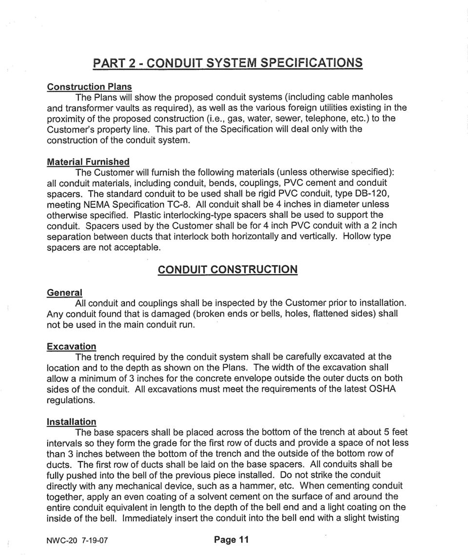
23 SECTION 1 CONDUIT SYSTEMS Material Selection The standard conduit material for the construction of underground conduit systems is PVC, Type DB-120. This conduit is stocked in 5 foot and 10 foot lengths in both 4 inch and 6 inch diameter. The 5 foot lengths are lightweight and easily handled, thus permitting installation in "tight" excavations where trench jacks and foreign utility crossings are encountered. Other conduit materials are a schedule 40 PVC. This conduit is stocked in 10 foot lengths and is used for bridge crossings and tunnel/casing installations. Galvanized steel conduit usage is limited to special installations requiring strength such as pole risers. Its use in underground conduit is not recommended because of the possibility of a cable fault damaging the conduit or welding itself to it. A damaged conduit can result in damaging the newly installed cable or make removal of the failed cable impossible. Plastic spacers are used to support the conduit and are manufactured in specific sizes and separation. The spacers stocked are for 4 inch and 6 inch PVC conduit with a 2 inch separation between ducts. The spacers interlock both horizontally and vertically and are stocked interlocked two wide. Spec. Page 1.11 lists all standard conduit materials for the 4 inch and 6 inch sizes which is presently stocked. Split PVC conduit is used for rebuilding damaged ductlines containing cables. This material uses the tongue and groove method and is available in 10 foot lengths. Smaller diameter conduit can be used for individual services to small customers where additional load should never be required. This material and its accessories are not stocked and must be purchased. Construction Plans Detailed drawings will be prepared by the Underground Network Engineering Section in Atlanta. Prints of these drawings will be furnished to the Company's Underground Network construction crew or to designated contractors who will bid the job. The successful bidder will be responsible for construction of the entire job as shown on these prints. These prints show the proposed conduit systems, manholes and/or transformer vaults required by the Company, as well as existing Company conduit systems, manholes and/or transformer vaults. The prints also show the various foreign utilities existing in the proximity of the proposed construction (i.e., gas, water, sewer, telephone, steam, etc.). This information was obtained from field surveys by the Company and from records kept by the various utilities. Previous experience with these utilities has indicated that their records are in many instances somewhat inaccurate and incomplete. Also, there are few records of the location of service taps. The user of these prints shall therefore be aware PAGE 1.01
24 that while due effort is exercised to assure accuracy, certain discrepancies might be found. The foreman responsible for the job (whether Company or contractor) should note any discrepancies found in the field as well as any minor changes in actual construction on his prints and return them to the Company for posting. Any major construction changes must be approved by the Underground Network Engineering Section in Atlanta. Materials Furnished to Contractor If the conduit system is to be constructed by a contractor, the Company will furnish the following materials: conduit, conduit bends, conduit couplings, conduit plugs, and conduit spacers. The contractor will be responsible for obtaining the material from the Company and keeping up with it once it is in his possession. He will also be responsible for the balance of the materials required for the construction of the conduit system. Excavation The trench required by the conduit shall be carefully excavated at the location and to the depth as shown on the construction drawing(s) furnished by the Underground Network Engineering Section in Atlanta. The width of the excavation shall be such as to allow a minimum of 3 inches for the concrete envelope outside the outside ducts on both sides of the conduit. Since the sides of the excavation are used for the sheathing forms, they should be trimmed smooth to give a uniform vertical surface throughout. For general excavation requirements see Power Delivery Bulletin No. 8-7, Safe Practices for Making Excavations. Conduit Construction All conduit and couplings shall be inspected prior to installation. Any conduit found that is damaged (broken ends or bells, holes, flattened sides) shall not be used in the main conduit run. However, it is permissible to use damaged conduit at locations requiring a short section if the damaged portion can be removed. Plastic base spacers shall be placed across the bottom of the trench at about 5 feet intervals so they form the grade for the first row of ducts. The bottom row of spacers shall provide a space of not less than 3 inches between the bottom of the trench and the outside of the bottom row of ducts. The first row of ducts shall be laid on the base spacers. All conduit shall be fully pushed into the bell of the previous piece installed. It is suggested that all PVC conduit be cemented together. However, if the fit between the conduit end and the bell end is tight, the cementing operation may be omitted. If the fit is tight, the conduit may have to be driven together by placing a block of wood against the last section of conduit and striking it with a hammer. Do not strike the conduit directly with the hammer. All conduit bends and all conduit installed in casings, tunnel liners or bridges must be cemented together to prevent it from coming apart during the concrete encasing, or temperature cycling for conduits installed on bridges. For conduit that is to be cemented together, apply an even coating of cement (C-7660/7662) on the surface of and around the entire conduit equivalent in length to the depth of the bell end. Immediately insert the conduit into the bell end with a slight twisting motion until it bottoms home. Do not twist or turn the conduit after it has bottomed out as this will weaken the bond PAGE 1.02
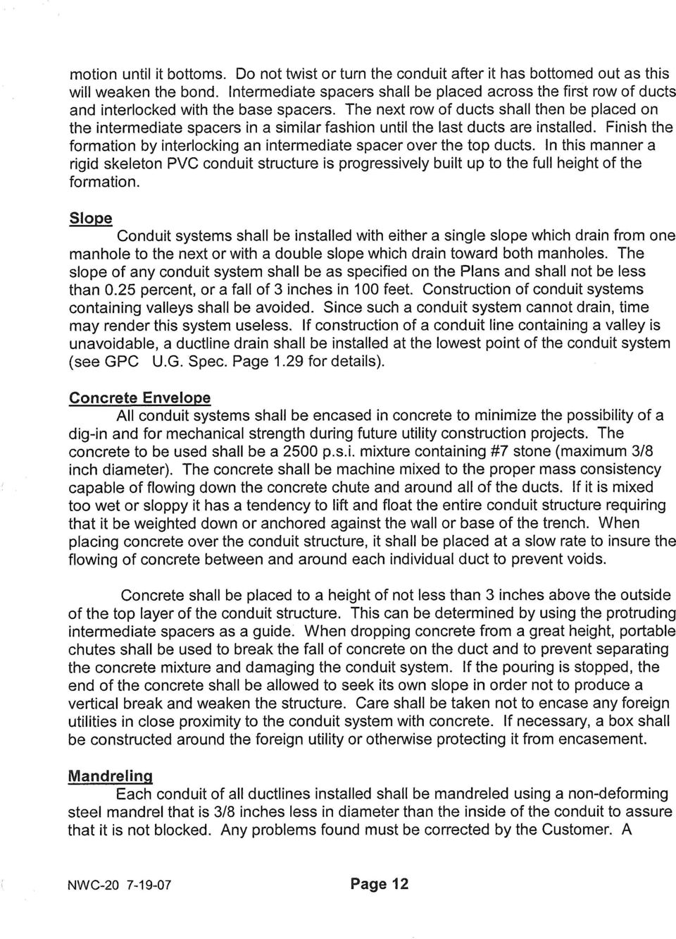
25 Intermediate plastic spacers shall be placed across the first row of ducts and interlocked with the base spacers. The next row of ducts shall then be placed on the intermediate spacers until the last ducts are installed. Finish up the formation by interlocking an intermediate spacer over the top ducts. In this manner a rigid skeleton PVC conduit structure is progressively built up to the full height of the formation. If an existing damaged conduit line containing cables is to be repaired, it shall be repaired using split plastic conduit using the following procedure: Carefully remove the concrete from the damaged conduit(s) and expose several inches of undamaged conduit on each side. The exposed conduit(s) should be squared off as much as possible. Cut the split conduit to the proper length and snap it in place around the cable. Secure the two halves with the plastic straps furnished. Use a split PVC repair coupling and install one at each end where the split conduit joins the existing conduit. Secure the couplings with nylon straps and wrap the couplings with plastic tape to prevent the entrance of concrete into the conduit. Finish the repair by encasing it in concrete. If the conduit does not contain a cable, it can be repaired with a section of standard PVC conduit. Slope Conduit lines shall be installed with either a single slope which drain from one manhole to the next or with a double slope with drain toward both manholes. The slope of any conduit line shall not be less than 0.25 percent, or a fall of 3 inches in 100 feet. Construction of conduit lines containing valleys shall be avoided. Since such a conduit system cannot drain, time may render this system useless. If construction of a conduit line containing a valley is unavoidable, a ductline drain shall be installed at the lowest point of the conduit system (see Spec. Page 1.29 for details). Concrete Envelope All conduit systems shall be encased in concrete to minimize the possibility of a digin and for mechanical strength during future utility construction projects. The concrete to be used shall be a 2500 psi mixture containing #7 stone (maximum 3/8 inch diameter) per Georgia Power Company Specification NWC-11. The concrete shall be machine mixed to the proper mass consistency capable of flowing down the concrete chute and around all of the ducts. If it is mixed too wet or sloppy it has a tendency to lift and float the entire conduit structure requiring that it be weighted down or anchored against the wall or base of the trench. When pouring concrete over the conduit structure, it shall be poured at a slow rate to insure the flowing of concrete between and under each individual duct to prevent voids. Concrete shall be poured to a height of not less than 3 inches above the outside of the top layer of the conduit structure. This can be determined by using the protruding intermediate spacers as a guide. When dropping concrete from a great height, portable chutes shall be used to break the fall of concrete on the duct and to prevent separating the concrete mixture and damage to the conduit system. If the pouring is stopped, the end of the pour shall be allowed to seek its own slope in order not to produce a vertical break and weaken the structure. Foreign utilities in close proximity to the conduit system shall not be encased in concrete. If necessary, construct a box around the foreign utility or otherwise protect it from encasement PAGE 1.03
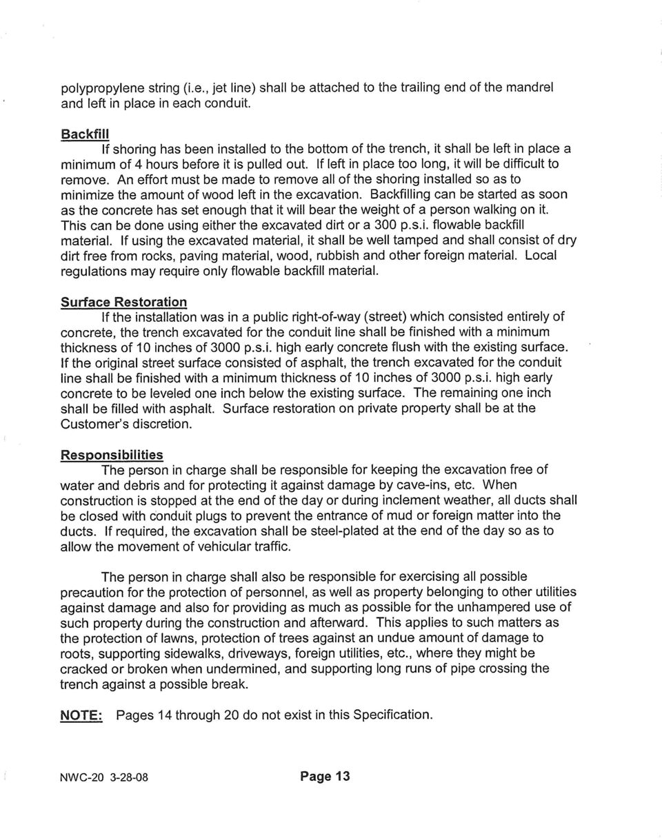
26 Backfill If shoring has been installed to the bottom of the trench, it shall be left in place a minimum of 4 hours before it is pulled out. If left in place too long, it will be difficult to remove. An effort must be made to remove all of the shoring installed so as to minimize the amount of wood left in the excavation. Backfilling can be started as soon as the concrete has set enough that it will bear the weight of a man walking on it. The backfilling shall be well tamped and shall consist of dry dirt free from rocks, paving material, wood, rubbish and other foreign material. The trench may also be backfilled with a flowable fill with a consistency of approximately 300 psi. Street Restoration If the original street surface consisted entirely of concrete, the trench excavated for the conduit line shall be finished with a minimum thickness of 10 inches of 3000 psi high early concrete flush with the existing surface. If the original street surface consisted of asphalt, the trench excavated for the conduit line shall be finished with a minimum thickness of 10 inches of 3000 psi high early concrete to be leveled one inch below the existing surface. The remaining one inch shall be filled with asphalt. If the conduit line was installed in a state highway, the street shall be repaired according to State Highway Specifications (see Spec. Page 1.93). If the conduit line was installed in a sidewalk, the sidewalk must be replaced with like kind material. Pole Riser When installing a conduit connection to a pole, a 10 foot section of G.I. conduit shall be temporarily installed on each conduit and properly aligned to the pole before any concrete is poured. The conduit coupling immediately below the sidewalk area must be one for adapting a PVC conduit to a G.I. conduit (see Spec. Page 1.57, item 4B). Abandoning Conduit Conduit lines to be abandoned shall be sealed at both ends with cement. Conduit bends at poles shall be cut level with the surface grade and sealed with cement. Responsibilities The foreman in charge shall be responsible for keeping the excavation free of water and debris and for protecting it against damage by cave-ins, etc. When construction is stopped at the end of the day or during inclement weather, all ducts shall be closed with conduit plugs to prevent the entrance of mud or foreign matter into the ducts. If required, the excavation shall be steel-plated at the end of the day so as to allow the movement of vehicular traffic. The foreman in charge shall also be responsible for exercising all possible precaution for the protection of property belonging to others than the Georgia Power Company against damage and also for providing as much as possible for the unhampered use of such property during the construction and afterward. This applies to such matters PAGE 1.04
27 as the protection of lawns, protection of trees against an undue amount of damage to roots, supporting sidewalks, driveways, foreign utilities, etc., where they might be cracked or broken when undermined, and supporting long runs of pipe crossing the trench against a possible break PAGE 1.05
28
29
30
31
32
33
REQUIREMENTS AND SPECIFICATIONS FOR HIGH VOLTAGE CUSTOMER BUILT FACILITIES PEPCO ENGINEERING
 REQUIREMENTS AND SPECIFICATIONS FOR HIGH VOLTAGE CUSTOMER BUILT FACILITIES PEPCO ENGINEERING Revised October, 2013 TABLE OF CONTENTS 1.0 INTRODUCTION... 3 2.0 REQUIRED DRAWINGS... 3 2.1 Site Plan... 3
APPLICATION FOR DEMOLITION & RIGHT-OF OF-WAY PERMIT
 APPLICATION FOR DEMOLITION & RIGHT-OF OF-WAY PERMIT City of Swartz Creek 8083 Civic Drive Swartz Creek, MI 48473 810-635-4464 Fee Received: $ Date: / / Receipt No: Demolition Permit (including Right of
CONSTRUCTION PERMIT REQUIREMENTS
 CONSTRUCTION PERMIT REQUIREMENTS Any work to be done in the City right-of-way (ROW), in a utility easement, and certain work on private property, requires an Engineering Inspection Permit from the Department
Wastewater Capital Projects Management Standard Construction Specification
 CITY AND COUNTY OF DENVER ENGINEERING DIVISION Wastewater Capital Projects Management Standard Construction Specification 10.1 Precast Concrete Pipe 10.1.1 General This section covers material requirements,
SECTION 02150 REMOVAL OR ABANDONMENT OF EXISTING UTILITIES AND UNDERGROUND STRUCTURES. 1. Trench excavation, backfill, and compaction; Section 02250.
 02150-1 of 6 SECTION 02150 REMOVAL OR ABANDONMENT OF EXISTING 02150.01 GENERAL A. Description Removal or abandonment of existing utilities and underground structures shall include, but not necessarily
LS 2540 SEWER LATERALS AND INSPECTION TEES
 LS 2540 SEWER LATERALS AND INSPECTION TEES A. Summary B. Submittals C. Site Information D. Sewer Pipe and Fittings E. Lateral Locations F. Lateral Installation G. Inspection Tee Installation H. Removal
Electric Engineering Division FIBER CONDUIT RULES AND REGULATIONS
 Electric Engineering Division FIBER CONDUIT RULES AND REGULATIONS TABLE OF CONTENTS I. RULES AND REGULATIONS A. TABLE OF CONTENTS... 2 B. TERMS AND DEFINITIONS... 3 C. DEVELOPER S/CONTRACTOR S RESPONSIBILITIES...
STANDARD SPECIFICATIONS FOR PRIVATE BUILDING SEWER LINES IN PUBLIC RIGHT-OF-WAY
 STANDARD SPECIFICATIONS FOR PRIVATE BUILDING SEWER LINES IN PUBLIC RIGHT-OF-WAY Approved and adopted as Official Document Number 800576 this 10th day of December, 1980 Donald R. Boyd, P.E., Director Water
Section 02702 SEWER PIPE INSTALLATION AND TESTING
 PART 1 - GENERAL Section 02702 SEWER PIPE INSTALLATION AND TESTING 1-1. SCOPE. This section covers the installation and testing of all sewer pipe furnished under the following specification sections: Concrete
SECTION 02400 - STORM DRAIN SYSTEM
 SECTION 02400 - STORM DRAIN SYSTEM CONTENTS: Part 1 - General... 1 1.01 Work Included... 1 1.02 Related Requirements... 1 1.03 Reference Standards... 1 1.04 Quality Assurance... 1 1.05 Measurement And
SECTION 16402 UNDERGROUND ELECTRIC SERVICE
 SECTION 16402 UNDERGROUND ELECTRIC SERVICE PART 1 GENERAL 1.1 SUMMARY A. Description of System 1. Furnish all labor, materials, and equipment for below grade work external to buildings as required, and
SECTION 6 SANITARY SEWER MAIN 6.01 SCOPE
 6.01 SCOPE The work covered by this section of the specifications consists of the furnishing of all plant, labor, materials, equipment and supervision and performing all operations involved in the construction
Section 402. STORM SEWERS
 402.02 Section 402. STORM SEWERS 402.01. Description. This work consists of constructing storm sewers of the size and class required, including excavation, bedding, and backfill. 402.02. Materials. Provide
Bethel Township Municipal Authority (BTMA) RESIDENTIAL SEWER CONNECTION MANUAL
 RESIDENTIAL SEWER CONNECTION MANUAL") 155 E. Front Street (rear) Lititz, PA 17543 Phone (717) 625-1930 Fax (717) 625-1931 Bethel Township Municipal Authority (BTMA) RESIDENTIAL SEWER CONNECTION MANUAL CONSTRUCTION SPECIFICATIONS AND DETAILS
155 E. Front Street (rear) Lititz, PA 17543 Phone (717) 625-1930 Fax (717) 625-1931 Bethel Township Municipal Authority (BTMA) RESIDENTIAL SEWER CONNECTION MANUAL CONSTRUCTION SPECIFICATIONS AND DETAILS
The work of this Section includes furnishing and installing Reinforced Concrete Pressure Pipe as shown on the Drawings and as specified.
 Section 33 0200- Page 1 of 4 PART 1 - GENERAL 1.1 DESCRIPTION OF WORK The work of this Section includes furnishing and installing Reinforced Concrete Pressure Pipe as shown on the Drawings and as specified.
Town House 11265 Center Highway North Huntingdon, PA 15642
 APPENDIX C SPECIFICATIONS FOR THE CONSTRUCTION OF BUILDING LATERAL SANITARY SEWERS DECEMBER 2004, INCLUDING AMENDMENTS ADOPTED ON FEBRUARY 6, 2008 AND APRIL 2, 2008; EFFECTIVE ON MAY 1, 2008 Town House
Elevating Your House. Introduction CHAPTER 5
 CHAPTER 5 Elevating Your House Introduction One of the most common retrofitting methods is elevating a house to a required or desired Flood Protection Elevation (FPE). When a house is properly elevated,
SANITARY SEWER SPECIFICATIONS
 SANITARY SEWER SPECIFICATIONS OCTOBER 2003 HARVEST-MONROVIA WATER, SEWER, AND FIRE PROTECTION AUTHORITY SECTION 1.00 1.10 Purpose The purpose of this document is to assemble the sewer specifications, policies,
SECTION 55 PIPE FOR STORM DRAINS AND CULVERTS (FAA D-701)
") SECTION 55 PIPE FOR STORM DRAINS AND CULVERTS (FAA D-701) 55-1 GENERAL The Contractor shall perform all work required by the plans for construction of pipe for storm drains, precast polymer trench drains
SECTION 55 PIPE FOR STORM DRAINS AND CULVERTS (FAA D-701) 55-1 GENERAL The Contractor shall perform all work required by the plans for construction of pipe for storm drains, precast polymer trench drains
Beacon Hill Sewer District Standard Specifications
 Beacon Hill Sewer District Standard Specifications Residential Gravity Side Sewer Including Design Criteria and Standard Construction Drawings Residential Gravity Side Sewer Design Criteria 1. Provisions
1.3.2 Method of construction and restoration of existing water service connections. This shall include:
 1.0 GENERAL 1.1 DESCRIPTION: This specification shall cover the rehabilitation of existing water lines using the GRUNDOCRACK PIPE BURSTING SYSTEM. Pipe bursting is a system by which the pneumatic bursting
3. Contractor shall ensure that all permits are obtained prior to any construction. Contractor shall be responsible for all utility fees.
 The following shall serve as the minimum requirements for contractors performing work in relation to the Authority s potable water and sanitary sewer system(s), appurtenances and service connections. General:
CITY OF VAUGHAN SCHEDULE O LOT GRADING DESIGN FOR RESIDENTIAL DEVELOPMENT
 Page 1 CITY OF VAUGHAN SCHEDULE O LOT GRADING DESIGN FOR RESIDENTIAL DEVELOPMENT CIVIC CENTRE 2141 MAJOR MACKENZIE DRIVE MAPLE ONTARIO L6A 1T1 905-832-2281 Page 2 SECTION 1 - GENERAL OBJECTIVES To provide
State of Illinois Department Of Transportation CONSTRUCTION INSPECTOR S CHECKLIST FOR STORM SEWERS
 State of Illinois Department Of Transportation CONSTRUCTION INSPECTOR S CHECKLIST FOR STORM SEWERS While its use is not required, this checklist has been prepared to provide the field inspector a summary
DESCRIPTION OF WORK:
 DEPARTMENT OF PUBLIC WORKS COUNTY OF HENRICO P.O. BOX 27032 RICHMOND, VIRGINIA 23273 PERMIT NO. One (1) copy of application and four (4) copies of plans are hereby made to the Director of Public Works
SECTION 02720 SANITARY SEWER AND STORM DRAIN SYSTEMS
 SECTION 02720 SANITARY SEWER AND STORM DRAIN SYSTEMS PART 1 GENERAL 1.01 SECTION INCLUDES A. The requirements for pipe material and installation in sewer and drainage collection systems. All materials
SANITARY SEWER SERVICE CONNECTION INSTRUCTIONS
 1 SANITARY SEWER SERVICE CONNECTION INSTRUCTIONS TABLE OF CONTENTS I. Introduction II. General Information and Requirements A. Applying for Sewer connection B. Excavation C. Cutting Concrete and Asphalt
SECTION 1 GENERAL REQUIREMENTS
 Page 1 of 6 SECTION 1 GENERAL REQUIREMENTS 1. SCOPE OF WORK: The work to be performed under the provisions of these documents and the contract based thereon includes furnishing all labor, equipment, materials,
CONTENTS. Yale University Design Standards. Underground Electrical Duct Bank. A. Summary. B. System Design and Performance Requirements
 16600 Underground Electrical Duct Bank This document provides design standards only, and is not intended for use, in whole or in part, as a specification. Do not copy this information verbatim in specifications
Storm Sewer Trenchless Upgrade Alternatives and Recommendations
 Storm Sewer Trenchless Upgrade Alternatives and Recommendations Background Approximately 1,930 feet of the 40-inch and 42-inch CMP storm sewer pipe from manhole M22 to manhole M12 will be evaluated for
TECHNICAL NOTE Culvert Sliplining and Lining of Casings with HPPipe
 TECHNICAL NOTE Culvert Sliplining and Lining of Casings with HPPipe TN 5.14 February 2010 Introduction It may be at times necessary, in an aging infrastructure, to rehabilitate drainage and sanitary lines
SECTION 33 31 00.11 GRAVITY SANITARY SEWERS
 SECTION 33 31 00.11 GRAVITY SANITARY SEWERS PART 1: GENERAL 1.01 SCOPE A. Gravity sanitary sewers and appurtenances. 1.02 SUBMITTALS A. Conform to requirements of Section 01 33 00 Submittals. B. Submit
Merrimac Municipal Light Department. Residential Developments Policy
 Merrimac Municipal Light Department Residential Developments Policy General: This document provides specific instructions for the provision of underground electrical facilities associated with the construction
REQUEST FOR QUALIFICATIONS FROM FOUNDATION REPAIR CONTRACTORS BROOMFIELD DEPOT FOUNDATION REHABILITATION PROJECT
 Project Description and Scope The City and County of Broomfield, Colorado (Broomfield) hereby solicits this Request for Qualifications (RFQ) to prequalify and shortlist up to five (5) foundation repair
TOWNSHIP OF BRIGHTON REQUEST FOR PROPOSALS SANITARY SEWER REPAIRS AND/OR GRINDER PUMP INSTALLATION
 TOWNSHIP OF BRIGHTON REQUEST FOR PROPOSALS SANITARY SEWER REPAIRS AND/OR GRINDER PUMP INSTALLATION April 25, 2014 DUE DATE/LOCATION: Friday, May 9, 2014 Bid forms and references are due by 9:30 A.M. at:
Underground Service Requirements and Instructions
 This packet includes all FKEC underground service requirements, instructions, procedures and drawings. If you are considering underground power service please review this document in its entirety (3 page
COMMERCIAL CONDUIT RULES AND REGULATION
 Electric Engineering Division COMMERCIAL CONDUIT RULES AND REGULATION S:\COO_ACM_US_Electric_Telecommunications\COO_ET_Engineering\Conduit Policies\Residential 1805 NE 30th Ave., Bldg. 400 Ocala, FL 34470-4875
Permit No. Permit Fee: $295.00. Permit Expires (D+90 days): Business Name: Applicants Name: Telephone Number: E-mail Address:
: Business Name: Applicants Name: Telephone Number: E-mail Address:") City of Woodland Park Internet Service Provider (IPS) Permit for Installation of Telecommunication Infrastructure within City Owned Rights-of-Way (up to five locations per single permit) Permit No. Permit
City of Woodland Park Internet Service Provider (IPS) Permit for Installation of Telecommunication Infrastructure within City Owned Rights-of-Way (up to five locations per single permit) Permit No. Permit
San Antonio Water System Standard Specifications for Construction ITEM NO. 1103 POINT REPAIRS AND OBSTRUCTION REMOVALS
 ITEM NO. 1103 POINT REPAIRS AND OBSTRUCTION REMOVALS 1103.1 DESCRIPTION: 1. Repair of sanitary sewer lines by replacing short lengths of failed pipe with new pipe. 2. Repair of service laterals located
SECTION 02110 - ASBESTOS CEMENT PIPE REPAIRS, DEMOLITION, AND DISPOSAL
 SECTION 02110 - ASBESTOS CEMENT PIPE REPAIRS, DEMOLITION, AND DISPOSAL PART 1 - GENERAL 1.1 WORK INCLUDED IN THIS SECTION A. The WORK of this Section includes the repair, demolition, and disposal of asbestos
SECTION 02763 POINT REPAIRS TO SANITARY SEWERS. A. Repairs to existing sewer lines by replacing short lengths of failed pipe.
 SECTION 02763 PART 1 G E N E R A L 1.01 SECTION INCLUDES A. Repairs to existing sewer lines by replacing short lengths of failed pipe. 1.02 UNIT PRICES A. Measurement for point repairs is on a unit price
PLEASE PRINT. Job Name: Job # City File No. SIDEWALK; DRIVEWAY APPROACH; CURB & GUTTER; PEDESTRIAN RAMP; STREET LIGHT; PLANTER STRIP;
 City of Santa Rosa ENCROACHMENT PERMIT APPLICATION Application#: Inspector: Liability Ins: WComp. Ins: FOR OFFICE USE ONLY NOTE: YOUR APPLICATION CANNOT BE PROCESSED WITHOUT COMPLETE INFORMATION IN AREAS
City of Hilshire Village Pine Creek Ln Reconstruction
 City of Hilshire Village Pine Creek Ln Reconstruction OVERVIEW The City will be soliciting bids for the Pine Creek Reconstruction Project with construction scheduled to begin in January 2015. This project
32-02.05 Precast Manhole Sections and Castings. These items shall conform to Section 31, "Storm Drain Installation," of these Standard Provisions.
 SECTION 32: SANITARY SEWER INSTALLATION 32-01 SCOPE. The Work shall consist of furnishing and installing sewer mains, manholes, laterals, cleanout fittings and appurtenances; and testing, flushing and
SECTION 31 20 00 EARTH MOVING
 SECTION 31 20 00 PART 1 - GENERAL 1.01 DESCRIPTION A. This Section describes the requirements for excavating, filling, and grading for earthwork at Parking Structure, new exit stair and as required to
AT&T Specifications Trenching Conduit Boxes and M anholes Aerial Entrance Masts Service Cabinets Bonding and Grounding
 AT&T Specifications Trenching Conduit Boxes and M anholes Aerial Entrance Masts Service Cabinets Bonding and Grounding A Guide for California Developers of Com m ercial Property This guide consists of
A. Contractor shall furnish, to the Engineer, all materials certifications available from the manufacturer for all required materials.
 PART 1 GENERAL 1.1 SCOPE A. This item shall include the work necessary for the installation of storm sewer line construction. B. Reference Section 3800 Trenching and Backfill and the General Conditions,
SERVICE LINE EXTENSION AND SERVICE LINE CONNECTION CONDENSED SANITARY SEWER SYSTEM INSTALLATION SPECIFICATIONS
 1001 SOUTH LEECHBURG HILL LEECHBURG, PA 15656 Phone: 724-845-9355 Fax: 724-845-1186 SERVICE LINE EXTENSION AND SERVICE LINE CONNECTION CONDENSED SANITARY SEWER SYSTEM INSTALLATION SPECIFICATIONS 1. General
SECTION LS 2530 SANITARY SEWERS. A. General: Submit the following in accordance with The General Conditions.
 SECTION LS 2530 SANITARY SEWERS PART 1 GENERAL 1.1 SUBMITTALS A. General: Submit the following in accordance with The General Conditions. 1. Product data for drainage piping specialties. 2. Shop drawings
SECTION 02630 STORM DRAINAGE SYSTEM
 SECTION 02630 PART 1 - GENERAL 1.01 DESCRIPTION A. Section includes specifications for storm drainage systems including modifications and connections to existing storm drainage systems. 1.02 REFERENCE
Section 2100-Trenching and Tunneling
 SECTION 5200 - STORM SEWER PART 1 - GENERAL 1.01 SCOPE: This Section covers installation of storm sewer mains and culverts. Topics include permits and fees, trench widths, pipe laying, bedding, initial
Lighthouse Engineering, L.L.C.
 Registered Engineering Firm (F: 9334) Phone: 214-577-1077 Fax: 214-224-0549 Website: www.lighthouseeng.com Email: Office@LighthouseEng.com Thursday, September 04, 2014 TO: Our Client RE: Initial Engineering
NEW SERVICE INSTALLATION STEPS. Common Slow Downs. Other Necessary Steps
 NEW SERVICE INSTALLATION STEPS Here is the step-by-step process required to fulfill your service installation request. Please take a few minutes to review the steps, become familiar with key milestones
SECTION 33 31 00.13 ABANDONMENT OF SEWER MAINS
 SECTION 33 31 00.13 ABANDONMENT OF SEWER MAINS PART 1: GENERAL 1.01 SECTION INCLUDES A. Abandonment in place, by cutting and capping, of existing sewers, junction structures, manholes, service lines, and
C. Section 014510 TESTING LABORATORY SERVICE.
 SECTION 014500 QUALITY CONTROL PART 1 GENERAL 1.01 RELATED REQUIREMENTS A. Drawings and General Provisions of Contract, including General and Special Conditions and other Division 1 Specification Sections,
San Antonio Water System Standard Specifications for Construction ITEM NO. 854 SANITARY SEWER LATERALS
 San Antonio Water System Standard Specifications for Construction ITEM NO. 854 SANITARY SEWER LATERALS 854.1 DESCRIPTION: This item shall govern sanitary sewer laterals installed in accordance with these
SECTION 08000 STORM DRAINAGE TABLE OF CONTENTS
 SECTION 08000 STORM DRAINAGE 08010 DESIGN A. Location B. Sizing TABLE OF CONTENTS 08020 MATERIALS A. Pipe Materials B. Structure Materials C. Installation D. Inlets and Outlets 08030 INSPECTIONS AND TESTING
SUBDRAINS AND FOOTING DRAIN COLLECTORS. A. Construct subdrains, subdrain cleanouts and outlets, and footing drain collectors.
 SUBDRAINS AND FOOTING DRAIN COLLECTORS PART 1 - GENERAL 1.01 SECTION INCLUDES A. Subdrains B. Subdrain Cleanouts and Outlets C. Footing Drain Collectors D. Storm Sewer Service and Connections 1.02 DESCRIPTION
TS 813 GROUNDING AND BONDING TTD 813.001 TRAFFIC SIGNAL INSTALLATION AND CONTROLLER CABINET GROUNDING SYSTEM TTD 813.005 CONTROLLER CABINET GROUNDING
 TORONTO TRANSPORTATION January 2012 TS 813 GROUNDING AND BONDING TABLE OF CONTENTS 1. DRAWINGS TTD 813.001 TRAFFIC SIGNAL INSTALLATION AND CONTROLLER CABINET GROUNDING SYSTEM TTD 813.005 CONTROLLER CABINET
Close-Out Documents... 9
 Water and Sanitary Sewer Service Connection Requirements Service Connection Requirements... 1 Application for Services... 2 Water Meter Application... 2 Wet Tap/Tie-in Connection Requirements... 3 Meter
TABLE OF CONTENTS. PUD SERVICE TERRITORY & CONTACTS... Page 1. NEW SERVICE QUESTIONNAIRE... Page 2. GENERAL... Page 3
 UNDERGROUND TABLE OF CONTENTS PUD SERVICE TERRITORY & CONTACTS... Page 1 NEW SERVICE QUESTIONNAIRE... Page 2 GENERAL... Page 3 TRENCHING SECONDARY (120/240 volts)... Page 3 CONDUITS FOR PUD-INSTALLED CONDUCTORS...
Reference Guide for Obtaining Permits and Utility Services For New Construction
 Reference Guide for Obtaining Permits and Utility Services For New Construction (Revised 04-2012) Table of Contents City Offices Telephone Numbers...1 Application for Utilities...2 Building Permits New
EXHIBIT A SCOPE OF SERVICES WATER SERVICE REPLACEMENT PROJECT. BROWARD OPERATIONS CENTER 5548 NW 9 th AVENUE FORT LAUDERDALE, FLORIDA 33309
 EXHIBIT A SCOPE OF SERVICES WATER SERVICE REPLACEMENT PROJECT BROWARD OPERATIONS CENTER 5548 NW 9 th AVENUE FORT LAUDERDALE, FLORIDA 33309 FLORIDA DEPARTMENT OF TRANSPORTATION DISTRICT FOUR 1.0 SCOPE OF
A. In this chapter, the following terms have the meanings indicated.
 08.07.02.01 Title 08 DEPARTMENT OF NATURAL RESOURCES Subtitle 07 FORESTS AND PARKS Chapter 02 Roadside Tree Care Authority: Natural Resources Article, 5-209 and 5-406, Annotated Code of Maryland.01 Purpose.
SPECIAL SPECIFICATION 5757 Power Duct System
 2004 Specifications CSJ 0353-04-088 SPECIAL SPECIFICATION 5757 Power Duct System 1. Description. This Item shall govern for the furnishing and installing of all materials, equipment, and labor listed in
Guidelines for Earthquake Bracing Residential Water Heaters
 Guidelines for Earthquake Bracing Residential Water Heaters Department of General Services Division of the State Architect In accordance with the Health and Safety Code Section 19215, the Division of the
CHAPTER 8 CIVIL DESIGN
 CHAPTER 8 CIVIL DESIGN A. GENERAL This Chapter includes standards and design considerations for other civil engineering design in structural, drainage and utilities. Design considerations for electrical
Underground Commercial Electric Service
 Underground Commercial Electric Service SCANA Corporation 2013 Revised: June 2013 Table of Contents SECTION PAGE I. Specification and Requirements 2 A. General B. Definition of Terms C. Company and Developer
Chapter. Restoration of Damaged Structures
 5 Chapter Restoration of Damaged Structures Bringing back a damaged structure to its pre-earthquake state and original strength is called restoration. This is the first step of building rehabilitation.
SPECIFICATIONS FOR THE INSTALLATION OF FIRE ALARM SYSTEMS, SPRINKLER SYSTEMS, AND MASTER BOXES IN THE POQUONNOCK BRIDGE FIRE DISTRICT
 SPECIFICATIONS FOR THE INSTALLATION OF FIRE ALARM SYSTEMS, SPRINKLER SYSTEMS, AND MASTER BOXES IN THE POQUONNOCK BRIDGE FIRE DISTRICT The purpose of these specifications is to insure that there are minimum
The Manitoba Water Services Board SECTION 022180 Standard Construction Specifications PIPE EXCAVATION, BEDDING AND BACKFILL Page 1 of 11
 Page 1 of 11 Part 1 General 1.1 DESCRIPTION OF WORK.1 The work described herein shall consist of the excavation of trenches (or excavation of tunnels); the supply and placing of bedding and backfill materials;
CARROLL COUNTY ELECTRICAL DEPARTMENT SERVICE POLICIES. EFFECTIVE MARCH 1, 1995 Revised 1/01/2013
 CARROLL COUNTY ELECTRICAL DEPARTMENT SERVICE POLICIES EFFECTIVE MARCH 1, 1995 Revised 1/01/2013 CARROLL COUNTY ELECTRICAL DEPARTMENT 103 WEST PARIS ST. P. O. BOX 527 HUNTINGDON, TENNESSEE 38344 Telephone
BUILDERS AND CONTRACTORS GUIDE FOR ELECTRIC SERVICE
 BUILDERS AND CONTRACTORS GUIDE FOR ELECTRIC SERVICE Toll Free Telephone Numbers Residential Services 800.454.3853 Commercial Services 800.653.5307 Utility Locating Company N.C. 800.632.4949 S.C. 888.721.7877
Section I - General. Page 1 of 5
 Section I - General City of Olivette Residential Sanitary Sewer Lateral Repair Program Policy & Procedures 1200 North Price Road, Olivette, MO 63132 P 314-993-0252 F 314-994-9862 A. The Owner of a single-family
CITY OF SELMA, TEXAS Inspection Checklist: Commercial
 Rev Y71004 The Permits and Inspections Department welcomes you to the City of Selma. The following information is provided to you as guidance through the inspection process. The City of Selma provides
How To Retaining Wall Guide
 How To Retaining Wall Guide Before you start: Consents and Engineering Building Consent Retaining walls over 1.5m high will require a building consent from the Local Body Council. Walls that carry extra
SECTION 33 41 13 PUBLIC STORM UTILITY DRAINAGE PIPING
 SECTION 33 41 13 PUBLIC STORM PART 1 - GENERAL 1.01 SECTION INCLUDES A. Storm drainage piping, fittings, and accessories at proposed station areas and locations other than under and immediately adjacent
Guidelines for Fiber Optic Cable Permits
 Guidelines for Fiber Optic Cable Permits NOVA District (Fairfax/Arlington) Permits www.virginiadot.org/business/fairfax-permits-main.asp Email: NOVAFairfaxPermits@VDOT.Virginia.gov 14685 Avion Parkway
SECTION 4Aggegate Subbase
 The contractor shall moist-cure the completed Lime Treated Subbase for a minimum of days before allowing any traffic on the compacted surface. The contractor shall be responsible for repairing any damages
STANDARD SPECIFICATIONS SECTION 02512 CLEANING AND LINING WATER MAINS
 STANDARD SPECIFICATIONS SECTION 02512 CLEANING AND LINING WATER MAINS PART 1 GENERAL 1.1 DESCRIPTION A. Section includes requirements for cleaning and lining existing cast iron and ductile iron water mains
REQUEST FOR QUALIFICATIONS (RFQ) DIVISION OF THE STATE ARCHITECT INSPECTOR OF RECORD SERVICES
 DIVISION OF THE STATE ARCHITECT INSPECTOR OF RECORD SERVICES") REQUEST FOR QUALIFICATIONS (RFQ) DIVISION OF THE STATE ARCHITECT INSPECTOR OF RECORD SERVICES 1. STATEMENTS OF QUALIFICATIONS REQUESTED The San Bernardino Community College District (District) Facilities
REQUEST FOR QUALIFICATIONS (RFQ) DIVISION OF THE STATE ARCHITECT INSPECTOR OF RECORD SERVICES 1. STATEMENTS OF QUALIFICATIONS REQUESTED The San Bernardino Community College District (District) Facilities
TOWN OF FARMINGTON, CT REQUEST FOR PROPOSALS FOR CONSTRUCTION EQUIPMENT RENTALS AND ON CALL CONSTRUCTION SERVICES
 TOWN OF FARMINGTON, CT REQUEST FOR PROPOSALS FOR CONSTRUCTION EQUIPMENT RENTALS AND ON CALL CONSTRUCTION SERVICES The Town of Farmington Department of Public Works is seeking proposals for the purpose
SECTION 18370 SIGNAL WIRE AND CABLE
 SECTION 18370 PART 1 - GENERAL 1.01 DESCRIPTION A. Section includes requirements for all cable and wire required for signal and signal power system wiring to wayside shelters, junction boxes, and factory
PRE INSTALLATION MANUAL
 REINFORCED CONCRETE PIPE PRE INSTALLATION INSPECTION & REPAIR MANUAL Kentucky Transportation Cabinet Kentucky Department of Highways Division of Materials 1227 Wilkinson Boulevard Frankfort, KY 40601 (502)
ARLINGTON COUNTY CODE. Chapter 18 PLUMBING AND GAS CODES
 Chapter 18 18-1. Title and Scope. 18-2. Definitions. 18-3. Availability of Codes. 18-4. Administration and Enforcement. 18-5. Registration of Contractors and Certification Requirements. 18-6. Permits and
DIVISION 4300 STORM DRAINAGE
 DIVISION 4300 STORM DRAINAGE SECTION 4305 STORM SEWER PART 1 - GENERAL 1.01 SCOPE This section covers the construction of storm sewers for the collection and transport of stormwater runoff. 1.02 REFERENCES
ARTICLE II (2) ARTICLE II - REQUIRED USE OF PUBLIC SEWERS. PARAGRAPH 020001 Purpose and Application.
 ARTICLE II - REQUIRED USE OF PUBLIC SEWERS. PARAGRAPH 020001 Purpose and Application.") ARTICLE II - REQUIRED USE OF PUBLIC SEWERS. PARAGRAPH 020001 Purpose and Application. Article II provides rules governing the allowable connection to the City POTW and the construction and inspection of
ARTICLE II - REQUIRED USE OF PUBLIC SEWERS. PARAGRAPH 020001 Purpose and Application. Article II provides rules governing the allowable connection to the City POTW and the construction and inspection of
Specification 6020. Underground Services - Subdivisions. Issue 12
 Building Industry Consulting Services (BICS) Specification 6020 Underground Services - Subdivisions Issue 12 Page 1 of 59 Distribution Conduit Are Provided By Others In Accordance With CRTC Tariff 21461,
Proposed Minimum Subterranean Termite Treatment Standards
 Proposed Minimum Subterranean Termite Treatment Standards Introduction This document is intended to serve as a model for states considering the adoption of standards for soil application of termiticides.
SIERRA LAKES COUNTY WATER DISTRICT P.O. Box 1039, Soda Springs, CA 95728-1039 (7300 Short Road, Serene Lakes)
") SIERRA LAKES COUNTY WATER DISTRICT P.O. Box 1039, Soda Springs, CA 95728-1039 (7300 Short Road, Serene Lakes) Maintenance Office Administrative Office Billing Office 530-426-7802 530-426-7800 916-332-4872
SIERRA LAKES COUNTY WATER DISTRICT P.O. Box 1039, Soda Springs, CA 95728-1039 (7300 Short Road, Serene Lakes) Maintenance Office Administrative Office Billing Office 530-426-7802 530-426-7800 916-332-4872
53.03 MATERIALS FOR SEWER LINER PIPE AND FITTINGS: The following materials are approved for installation in sanitary sewer lines:
 Division 53: Slip-Lining of Existing Sewer Line 53.01 GENERAL: This section includes all labor, materials, transportation, equipment necessary to rehabilitate by means of Instituform deteriorated sections
Guidelines for Excavations
 O c t o b e r 2 0 0 1 Guidelines for Excavations in the vicinity of gas lines Technical Standards & Safety Authority Putting Public Safety First Guidelines for Excavations in the Vicinity of Gas Lines
Construction Management At-Risk
 Oconee County Schools P.O. Box 146, 34 School Street Watkinsville, GA 30677 706-769-5130 706-769-3513 REQUEST FOR PROPOSALS ISSUE DATE: March 10, 2016 RFP REF: Construction Management At-Risk Construction
Civil. 2. City of Seattle Supplement to the Specification for Road, Bridge and Municipal Construction, most current addition.
 Design Guide Basis of Design This section applies to the design and installation of earthwork and backfill. Design Criteria No stockpiling of excavation materials is allowed unless the Geotechnical Engineer
Gas Meter Clearances and Service Installation Requirements
 March 2015 Gas Meter Clearances and Service Installation Requirements Builder/Owner/Developer Requirements Call PSE s Customer Construction Services 1-888-321-7779 or visit PSE.com/CustomerConstruction
DESIGN AND CONSTRUCTION GUIDELINES AND STANDARDS DIVISION 33 UTILITIES 33 00 00 SITE UTILITIES
 SECTION INCLUDES Domestic Water Fire Water Service Water Well Sanitary Sewer Storm Drains Foundation Drainage RELATED SECTIONS 03 30 00 Concrete 21 00 00 Fire Suppression - Sprinklers 22 00 00 Plumbing
CITY OF ELBERTON, GEORGIA REQUEST FOR PROPOSAL
 CITY OF ELBERTON, GEORGIA REQUEST FOR PROPOSAL INVITATION FOR BIDS RFP # 2014 01 RFP TITLE TREE TRIMMING SERVICES FOR POWER LINES ISSUE DATE June 28, 2013 DUE DATE July 29, 2013 at 2:00 PM IMPORTANT NOTE:
Town of Durham. Selectman s Office P.O. Box 428 Durham, CT 06422. Request for Qualification
 Town of Durham Selectman s Office P.O. Box 428 Durham, CT 06422 Request for Qualification REQUEST FOR LETTERS OF QUALIFICATIONS FOR PROFESSIONAL ARCHITECTURAL SERVICES Board of Selectmen Laura L. Francis
Denver Water Capital Projects Contractor Prequalification REQUEST FOR QUALIFICATIONS
 RFQ Term: 9/29/2015 12/1/2019 Denver Water Capital Projects Contractor Prequalification REQUEST FOR QUALIFICATIONS Denver Water (DW), in an effort to improve the administration and efficiency, has initiated
CONCRETE SEGMENTAL RETAINING WALL SYSTEM
 CONCRETE SEGMENTAL RETAINING WALL SYSTEM PART 1: GENERAL SPECIFICATIONS 1.01 Work Included A. Work shall consist of furnishing and constructing a Rockwood Classic 8 with PCS unit segmental retaining wall