300/75,1200, 2400bps Asynchronous Bell103/212 - CCITT V.22, V.22bis QUAM in 2400bps, DPSK in 1200bps, FSK in 0-300bps
|
|
|
- Emerald Skinner
- 8 years ago
- Views:
Transcription
1 The Performance Champions USER GUIDE Technical Specifications... Data Rates: Compatibility: Modulation: Operation: Command Set: Transmit Level: Receive Sensitivity Dropout Level: Non-Volatile Memory: Power: Size: Weight: Environment: The HA2400LP is designed for those applications where no external source of power is available. The HideAway derives its power from two isolated sources: Power from the RS232 interface (TXD, RTS & DTR) activates the HideAway's RS232 drivers, the AT Command set controller and the optical relay that picks up the telephone line; Power from the telephone line then activates the data pump and ancillary telephone line components It is essential, therefore, that the RS232 connection to your HA2400LP provides TED, RTS & DTR signals from which the HA2400 can draw its initial operating power, and that the unit is connected to a dial-up, not leased, telephone line. 300/75,1200, 2400bps Asynchronous Bell103/212 - CCITT V.22, V.22bis QUAM in 2400bps, DPSK in 1200bps, FSK in 0-300bps Full or half-duplex Hayes AT; 40 character buffer -12dBm 43dBm 48dBm Two stored user profiles Four stored phone numbers Pin & Line Powered; No battery or AC adapter required 2.2"x3"x0.83" 2.3 ounces 0 to 40 C Operating -40 to 100 C Storage 0 to 95% (Non-condensing)
 activates the HideAway's RS232 drivers, the AT Command set controller and the optical relay")
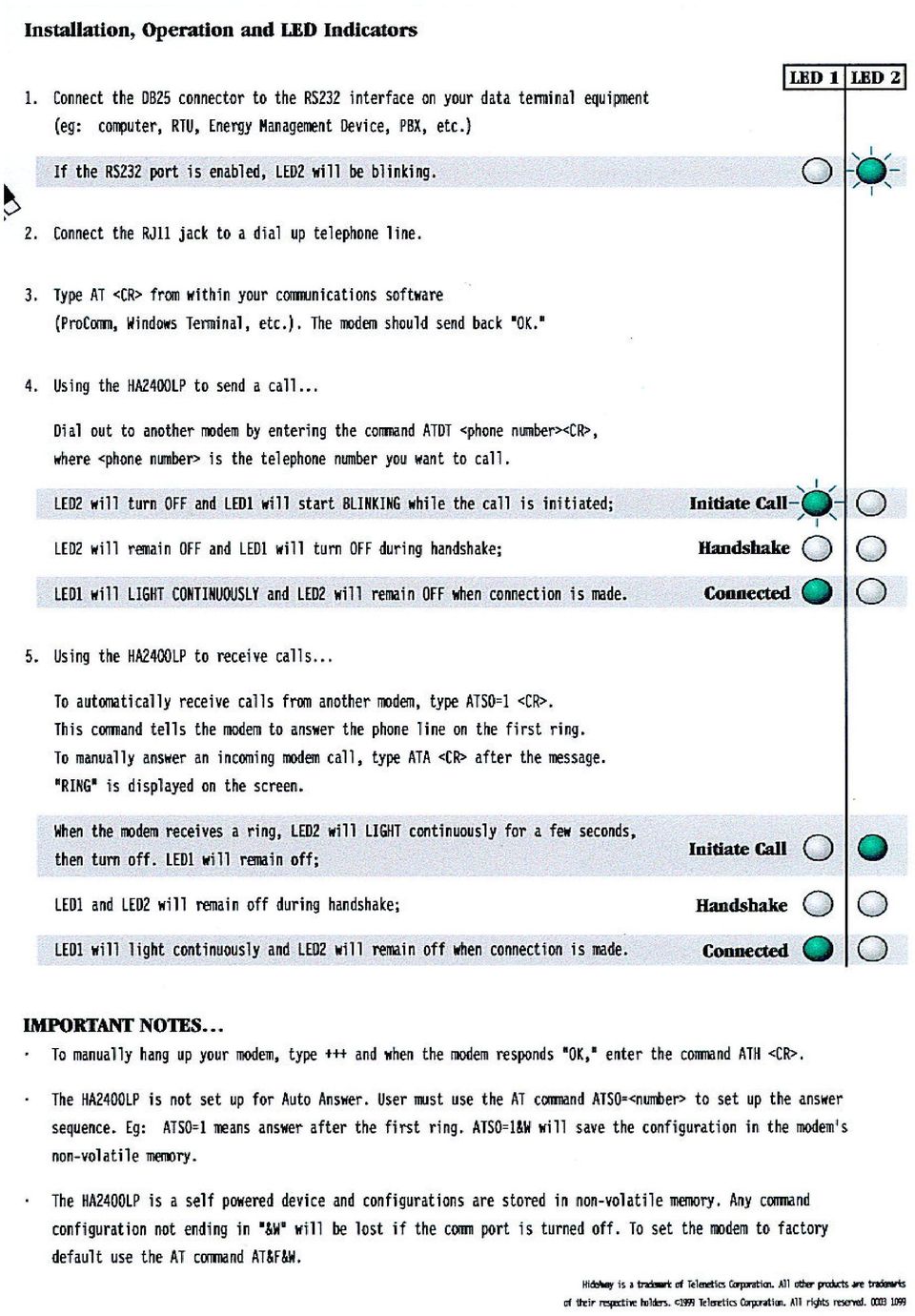
2 Installation, Operation and LED Indications Connect the DB25 connector to the RS232 interface on your data terminal equipment ie, computer, RTU, Energy Management Device, PBX, etc.) If the RS232 port is enabled, LED2 will be BLINKING. 2. The Data equipment must have pins 2, 4, 20, high (at least 3 to 5 volts) for unit to answer the phone line 2. Connect the RJ11 jack to a dial up telephone line. 3. Type AT <CR> from within your communications package - The modem should send back ~OK". 4. Using the HA2400LP to send a call... Dial out to a bulletin board or another modem by entering the command ATDT <phone number><cr>, where <phone numbed is the telephone number you want to call. LED2 will turn OFF and LED1 will start BLINKING while the call is initiated; LED2 will remain OFF and LED1 will turn OFF during handshake; LED1 will LIGHT CONTINUOUSL Y and LED2 will remain OFF when connection is made. NOTE: For pulse phones, use ATDP<phone number><cr>. Or if you prefer you can use the auto-dialer feature of your software program to dial out. 5. Using the HA2400LP as a host... To automatically receive calls from another modem, type ATSO=1 <CR>. This command tells the modem to answer the phone line on the first ring. To manually answer an incoming modem call, type ATA ACT> aft, the modem types "Ring" on the screen. When modem receives a ring, LED2 will LIGHT CONTINUOUSLY for a few seconds, then turn OFF. LED1 will remain OFF; LED1 and LED2 will remain OFF during handshake; LED1 will LIGHT CONTINUOUSLY and LED2 will remain OFF when connection is made. 6. To manually hang up your modem, type +++ and when the modem responds "OK", enter the command ATH <CR>. IMPORTANT NOTES... The HA2400LP may not be set up for Auto Answer. User can use the AT command ATSO=<number>(1 or 0) to set up the answer sequence. ATSO=1 means answer after the first ring. ATSO=1&W will save the configuration in the modem's nonvolatile memory. The HA2400LP is a line powered device and configurations are stored in non-volatile memory. Any command configuration not ending in "&W" will be lost if the comm port is turned off. To set the modem to factory default use AT command AT&F&W but you will lose or the settings you stored under AT&W.

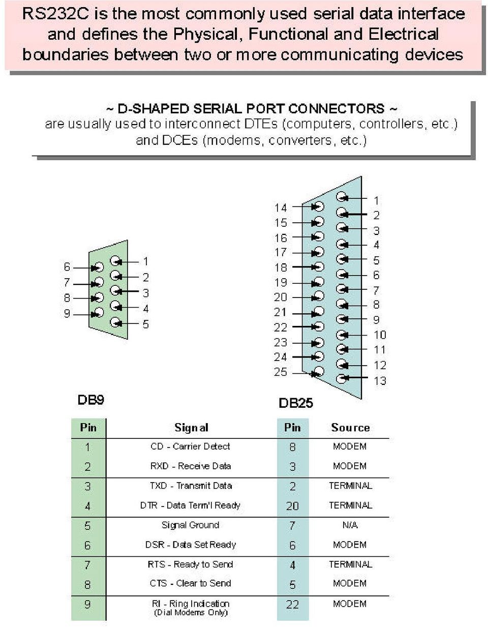
3 If the RS232 port is enabled, LED2 will be BLINKING The Data equipment must have pins 2, 4, 20, high - in the idle (at least 3 to 5 volts) for unit to answer the phone line NOTE 1 - It is essential, that the RS232 connection to your HA2400LP provides TD, RTS & DTR signals from which the HA2400 can draw its initial operating power, and that the unit is connected to a dial-up, not leased, telephone line. Electronic data communications between elements will generally fall into two broad categories: single-ended and differential. RS232 (single-ended) was introduced in 1962, and despite rumors for its early demise, has remained widely used through the industry. Independent channels are established for two-way (full-duplex) communications. The RS232 signals are represented by voltage levels with respect to a system common (power / logic ground). The "idle" state (MARK) has the signal level negative with respect to common, and the "active" state (SPACE) has the signal level positive with respect to common. RS232 has numerous handshaking lines (primarily used with modems), and also specifies a communications protocol. The RS-232 interface presupposes a common ground between the DTE and DCE. This is a reasonable assumption when a short cable connects the DTE to the DCE, but with longer lines and connections between devices that may be on different electrical busses with different grounds, this may not be true. RS232 data is bi-polar TO +12 volts indicates an "ON or 0-state (SPACE) condition" while A -3 to -12 volts indicates an "OFF" 1-state (MARK) condition... Modern computer equipment ignores the negative level and accepts a zero voltage level as the "OFF" state. In fact, the "ON" state may be achieved with lesser positive potential. This means circuits powered by 5 VDC are capable of driving RS232 circuits directly, however, the overall range that the RS232 signal may be transmitted/received may be dramatically reduced. The output signal level usually swings between +12V and -12V. The "dead area" between +3v and -3v is designed to absorb line noise. In the various RS-232-like definitions this dead area may vary. For instance, the definition
 was introduced in 1962, and despite rumors for its early demise, has remained widely used through the industry.")
4 for V.10 has a dead area from +0.3v to -0.3v. Many receivers designed for RS-232 are sensitive to differentials of 1v or less. This can cause problems when using pin powered widgets - line drivers, converters, modems etc. These type of units need enough voltage & current to power them self's up. Typical URART (the RS-232 I/O chip) allows up to 50ma per output pin - so if the device needs 70ma to run we would need to use at least 2 pins for power. Some devices are very efficient and only require one pin (some times the Transmit or DTR pin) to be high - in the "SPACE" state while idle. An RS-232 port can supply only limited power to another device. The number of output lines, the type of interface driver IC, and the state of the output lines are important considerations. The types of driver ICs used in serial ports can be divided into three general categories: Drivers which require plus (+) and minus (-) voltage power supplies such as the 1488 series of interface integrated circuits. (Most desktop and tower PCs use this type of driver.) Low power drivers which require one +5 volt power supply. This type of driver has an internal charge pump for voltage conversion. (Many industrial microprocessor controls use this type of driver.) Low voltage (3.3 v) and low power drivers which meet the EIA-562 Standard. (Used on notebooks and laptops.)
 to be high - in the \"SPACE\" state while idle.")
5
6 SUMMARY OF THE ROCKWELL "AT" COMMAND SET To communicate using the modem, use an asynchronous communication program. The command set for the modems is compatible with the Hayes command set. The modem is controlled and configured by the AT (attention command). Each command consists of the following elements (with the exception of the A/and the +++ command that will be discussed later). A command is not entered until a carriage return <ENTER> is entered. Spaces entered are ignored. For example, to enter the command `Answer', type ATA and <ENTER>. When a carriage return is received, the commands are performed in the order in which they are sent to the modem. If more than 40 characters are sent to the modem, an error occurs and all commands must be re-entered.

7 A common configuration for a remote modem is to answer the call and hang up on loss of carrier. To do this the RS232 interface has to be set for the correct configuration. Option if the Computer uses pins 2, 3, & 7 only - Set the AT commands as follows ATS0=1 (modem will answer on the first ring) AT&D0 (modem will ignore DTR) factory default is AT&D1 which allows the modem to answer only if DTR is high. AT&V to check the state of the "S" registers use AT&V AT&W0 Don't forget to burn the new codes into E-PROM by AT&W0 or W1 To see your typing you made need to turn on E1 for the modem to echo back responses. Some software does not like it's data echoed back so don't forget to check E1/E0 if your software is acting strange. Note: you may want to put the modem into a quiet mode - ATQ1 (ATQ0 is the default) modem does not send result codes - which can confuse the computer. A good configuration for a dumb mode operation is AT&F&C1&D0E0Q1S0=1&W0 or W1

8 BASIC AT COMMANDS for the 2,400 modem Command and Data Modes When you first start up your communications software, you will be in COMMAND mode. In other words, you have not dialed out and linked up to a remote modem. In COMMAND mode, local commands (called AT Commands) are active. After dialing out and successfully linking-up, you are in DATA mode and AT Commands are no longer active. In DATA mode, you must use the ESCAPE code (. ) to temporarily suspend transmission to the remote modem and re-enter COMMAND mode. The ATO<CR> command (see below) reenters DATA mode. AT Command Summary All of the following commands must be preceded with the characters AT and followed by a carriage return (the <CR>, < <enter> >, or < <return> > key). For example, typing AT<CR> will cause the modem to print "OK" on the screen, and typing AT&V<CR> will print the current configuration profile on the screen. The one notable exception is the A/ command, which will execute the previous AT Command without a <CR>. Throughout the rest of the manual, we will use the <CR> symbol to represent the enter key. Be sure to do a AT&W0 that will write the changes you may have made to the 0 register so the modem will not lose it's settings after a power outage You may want to set the modem up so it will echo your key strokes with the E1 command - NOTE some software will have problems with an echo so you may need to set it to E1. If your RS232 interface doesn't supply DTR you will need to set the &D to
 to temporarily suspend transmission to the remote modem and re-enter COMMAND mode. The ATO<CR> command (see below) reenters DATA mode.")
9 Basic Commands AT-Command prefix required before all commands except A/ and ESCAPE sequences <CR>-Terminates command line A/-Repeat last command (does not use <CR>) Escape code sequence (returns to COMMAND mode from DATA mode) A-Answers a telephone call Bn-Select Bell or CCITT for 1200 bps connection B0-CCITT V.22 FOR 1200 bps communication Bl-Bell 212A for 1200 bps communication Cn-Carrier Control C0-ERROR C1-OK D-Dial the number which follows (see DIAL commands) En-Command set echo control E0-Echo off E1-Echo on Fn-On-line echo F0-ERROR Fl-OK Hn-Off-hook control H0-Hangup phone line H1-Pickup phone line

10 In-Identify the modem type I0-Report the product code I1-Calculate the firmware ROM checksum I2-Verify the firmware ROM checksum I3-Report the firmware and revision levels I4-Report modem capabilities and features Ln-Speaker volume control Acknowledged Mn-Speaker control Acknowledged O-Go back to DATA mode P-Use pulse dialing Qn-Disables (quiets) command responses Q0-Enable results Q1-Disable results Sn-Select a S register Sn=-Set S register to new value Sn?-Show value of S register T-Use tone dialing Vn-Use verbose result codes V0-Result codes are numeric V1-Result codes are verbose Xn-Extended dialing result codes X0-Send result codes 0 through 4; BUSY and DIAL TONE detect disabled X1-Send result codes 0 through 5, 10; BUSY and DIAL TONE detect disabled X2-Result codes 0 through 6, 10 enabled; BUSY detect disabled, DIAL TONE detect enabled X3-Result codes 0 through 5, 7, 10 enabled;

11 BUSY detect enabled, DIAL TONE detect disabled X4-Result codes 0 through 8, 10 enabled; BUSY and DIAL TONE detect enabled Yn-Enable long space disconnect Y0-Disable long space disconnect Y1-Enable long space disconnect Zn-Reset the modem Z0-Reset and use stored profile 0 Z1-Reset and use stored profile 1, -Pause for the value (in seconds) stored in register S8 Dial Commands DP-Pulse dial the telephone number DS=n-Dial with previously stored number DT-Tone dial the telephone number DW-Wait for dial tone D; - Stop dialing and wait for more commands D@ - Wait for 5 seconds of silence D! - Hang up for 1/2 of a second (Flash) D,-Pause for seconds as determined by register S8 0 through 9, A, B, C, D, #, *- Dial Digits/Characters When the modem is dialing a phone number, any key will abort the current dialing command.
 D,-Pause for seconds as determined by register S8 0 through 9, A, B, C, D, #, *- Dial Digits/Characters When the modem is dialing a phone number, any key will")
12 Extended Commands &Cn-EIA RS-232 DCD control &C0-Always on &C1-On only when carrier detected &Dn-EIA RS-232 DTR control Acknowledged &En-Dialing echo control &E0-Disable dialing echo &E1-Enable dialing echo &F-Accept factory settings &Gn-Guard tone control &G0-Guard tones disabled &Gl-Guard tone disabled &G Hz Guard tone enabled &Ln-Leased-line control Acknowledged &Pn-Select pulse dial make/break ratio &P1-39 through 61 make/break at 10 pps &P2-33 through 67 make/break at 10 pps &Sn-EIA RS-232 DSR control Acknowledged &V-VIEW current configuration profile &Wn-Write to stored profile &W0-Write settings to stored profile 0 &W1-Write settings to stored profile I &Yn-Select stored profile for power up &Y0-Use profile 0 on power up &Y1-Use profile I on power up &Zn=val-Store dial string (up to 36 characters) in nonvolatile memory location numbers 0 through 3

13 Register Commands * means value is stored by &Wn (0 or1) command. S0*-Number rings until auto answer S0=1 will answer one the first ring S1-Number of rings received S2-Escape Character S3-Carriage-return character S4-Line-feed character S5-Backspace character S6-Time for dial tone S7-Time to wait for connection S8-Pause time for comma S9-Carrier detect time S10-Carrier lost detect time S11-Tone dialing speed S12-Escape-code guard time S14*-bit-mapped options register S21*-bit-mapped options register S22*-bit-mapped options register S23*-bit-mapped options register S27*-bit-mapped options register Result Code Summary * OK-Command was executed without error * 1 CONNECT-Modem has detected carrier and has gone DATA * 2 RING-Modem has detected ringing

14 * 3 NO CARRIER-Carrier has been lost and call has been hung up * 4 ERROR-Error in command line * 5 CONNECT 1200-Modem has connected at 1200 bps; Bell 212 or V.22 connection * 6 NO DIAILTONE-has been detected * 7 BUSY-A busy signal has been detected * 8 NO ANSWER-Silence was not found * 10 CONNECT 2400-Modem has connected at 2400 bps; V-22 connection Error Diagnostics Is the computer talking with the modem? When you type AT<CR>, "OK" should be displayed. If the modem does not respond: 1. Make sure the modem is firmly connected to the computer. 2. Verify the communication program is configured to the correct communications port (COM L, COM2:, COM3:, or COM4:). 3. Verify the baud rate (2400, 1200, or 300) and check parity (even, odd, none). 4. If the modem still does not respond, type AT&F<CR>. This will reset the modem to the original factory settings. 5. Try unplugging the modem and plugging it back in to ensure clean contact connections. If the modem responds, but characters are not displayed, type ATEI <CR>. This tells the modem to echo commands to the screen....characters are displayed double, type ATE<CR>. This turns the echo feature off. Modem does not answer. If the modem does not answer an incoming call, type ATSO = I < CR>.
. 3. Verify the baud rate (2400, 1200, or 300) and check parity (even, odd, none). 4.")
15 Modem will not dial a telephone number. If the computer displays NO DIALTONE, the modem is not receiving a dial tone. Connect a standard telephone to the telephone line to verify a dial tone. If you do not hear dial tone, something is wrong with either your telephone cable or telephone line. Try another cable or line. On some telephone lines connected to internal telephone systems, the telephone lines are not standard and will not work with standard telephones. Such lines will not work with this modem. Adapters are available to convert these lines so they may work with standard telephone equipment. Modem can dial but can't communicate. If you cannot communicate properly, something may be wrong with the other system. Try calling a different modem. Unusual characters appear on the screen. If you can dial, but unusual characters appear on the screen while communicating, check the communications settings of your communications software. The most common settings are 7EI (7 bits, even parity, I stop bit) and 8N 1 (8 bits, no parity, I stop bit). Modem connects but cannot communicate. Another possibility is that your modem and software are set for different speeds. In other words, you will be unable to communicate at 2400 bps with modems linked at 1200 bps. Check your speed settings. Your modem disconnects. During communications the modem may disconnect from the phone line if- 1. It fails to connect to the remote modem. 2. It detects a loss of carrier from the remote modem. 3. You enter the escape and Hook command. 4. Turn off power to the computer.

16
Low Speed Modems for Dial and Leased Circuits 2400E-2 (Stand Alone) 2400R-2 (Rack Mount) 2400E-4 (Stand Alone) 2400R-4 (Rack Mount)
 2400R-2 (Rack Mount) 2400E-4 (Stand Alone) 2400R-4 (Rack Mount)") Low Speed Modems for Dial and Leased Circuits 2400E-2 (Stand Alone) 2400R-2 (Rack Mount) 2400E-4 (Stand Alone) 2400R-4 (Rack Mount) QUALITY COMMUNICATIONS PRODUCTS Made in the U.S.A. 11-1010-002 INTRODUCTION
Low Speed Modems for Dial and Leased Circuits 2400E-2 (Stand Alone) 2400R-2 (Rack Mount) 2400E-4 (Stand Alone) 2400R-4 (Rack Mount) QUALITY COMMUNICATIONS PRODUCTS Made in the U.S.A. 11-1010-002 INTRODUCTION
Dial-Up / Leased-Line Modem. User Manual. AGM Electronics, Inc Dial-Up / Leased-Line Modem, Series ( ) 5019-1 Manual Rev A + - DLM CTS RTS DTR DSR
 5019-1 Manual Rev A + - DLM CTS RTS DTR DSR") AGM Electronics, Inc Dial-Up / Leased-Line Modem, Series ( ) 5019-1 Manual Rev A User Manual + - CD CTS RTS DTR. DSR RI RX TX PHONE LINE DLM Dial-Up / Leased-Line Modem Dial-Up / Leased-Line Modem CONTENTS
AGM Electronics, Inc Dial-Up / Leased-Line Modem, Series ( ) 5019-1 Manual Rev A User Manual + - CD CTS RTS DTR. DSR RI RX TX PHONE LINE DLM Dial-Up / Leased-Line Modem Dial-Up / Leased-Line Modem CONTENTS
Date Rev. Details Author
 Jtech engineering ltd J - Te c h E n g i n e e ring, L t d. 11080 Bond Boulevard Delta BC V4E 1M7 Canada Tel: 604 543 6272 Fax: 604 543 6476 http://www.jtecheng.com AUTODIALER USER S MANUAL REVISION HISTORY
HOW TO USE YOUR INTELE-MODEM
 HOW TO USE YOUR INTELE-MODEM 305-008800 Ultratec, Inc. 450 Science Drive Madison, WI 53711 (608) 238-5400 (Voice/TTY) Fax: (608) 238-3008 Email: service@ultratec.com www.ultratec.com First Edition October
Technical Note #14. Phone Modem Device Support. GE ED&C Home Search ED&C GE ED&C Power Management Home GE ED&C PMCS Home
 1 of 7 GE ED&C Home Search ED&C GE ED&C Power Management Home GE ED&C PMCS Home GE Power Management Control System Description Software Hardware Operation Product Support Operator Interfaces F A Q s App
System Requirements. Hiro H50113
 1 Hiro H50113 System Requirements Hiro H50113 Computer with Pentium 200 MMX or higher processor. Windows 2000, Windows XP Home / Professional, XP Professional x64 Edition, Vista 32 / 64 Families, Windows
1. Make sure that no client accounts are open. 2. Click on Setup, then click Modem. The Modem Setup window will appear.
 SECURITY SYSTEM MANAGEMENT SOFTWARE FOR WINDOWS WINLOAD MODEM SETUP The modem setup is a very important step in the connection process. If the modem setup is not properly completed communication between
Quectel Cellular Engine
 Cellular Engine GSM UART Port Application Notes GSM_UART_AN_V1.01 Document Title GSM UART Port Application Notes Version 1.01 Date 2009-11-16 Status Document Control ID Release GSM_UART_AN_V1.01 General
Accessing Diagnostics using a Dialup Modem
 Purpose This application note is meant to guide a user through the setup and use of a dial-up modem to retrieve diagnostics data from a remote master. Equipment Used This application note was written specifically
PCM-3600 PC/104 Fax/Modem Module
 PCM-3600 PC/104 Fax/Modem Module Copyright Notice This document is copyrighted, 1996, by AAEON Technology Inc. All rights are reserved. AAEON Technology Inc. reserves the right to make improvements to
LOW COST GSM MODEM. Description. Part Number
 Dual Band 900 / 1800 MHz Fax, SMS and Data Integral SIM Card holder Siemens TC-35i GSM Engine Rugged Extruded Aluminium Enclosure Compact Form Factor 86 x 54 x 25mm RS232 Interface with Auto baud rate
18.04.2005 version 3.1. Security modem with USB port user guide
 18.04.2005 version 3.1 Security modem with USB port user guide Introduction Congratulations on selecting the new SECURITY MODEM data transfer device. We designed this modem for special users who are involved
1MRS119000 Plug-in Modem. Operator s manual
 1MRS119000 Plug-in Modem Operator s manual 1MRS 750577-MUM EN Issued 98-06-02 Version A Checked MKa Approved OV 1MRS119000 Plug-in Modem Data subject to change without notice Contents 1.0 General... 4
LS-101 LAN to Serial Device server. User s Manual
 LS-101 LAN to Serial Device server User s Manual Revision History Revision No Date Author Remarks 0.1 August 29, 2001 IDC Initial document INTRODUCTION Overview Almost all instruments and most industrial
SWITCHED TELEPHONE NETWORK LEASED LINE
 Distribué par : Contact : hvssystem@hvssystem.com Tél : 0326824929 Fax : 0326851908 Siège social : 2 rue René Laennec 51500 Taissy France www.hvssystem.com MTi 133-1 V34 33 600 b/s INDUSTRIAL MODEM SWITCHED
Vector F336E/2LL MODEM USER'S MANUAL
 Vector F336E/2LL MODEM USER'S MANUAL CONTENTS CHAPTER 1 INTRODUCTION Features----------------------------------------------------------------1 Package Contents-----------------------------------------------------1
Modbus Communications for PanelView Terminals
 User Guide Modbus Communications for PanelView Terminals Introduction This document describes how to connect and configure communications for the Modbus versions of the PanelView terminals. This document
MCB3101 (Class I) WiRobot Serial Bluetooth Wireless Module User Manual
 WiRobot Serial Bluetooth Wireless Module User Manual") MCB3101 (Class I) WiRobot Serial Bluetooth Wireless Module User Manual Version: 1.0.1 Dec. 2005 Table of Contents I. Introduction 2 II. Operations 2 II.1. Theory of Operation 2 II.2. Configuration (PC-PC
MCB3101 (Class I) WiRobot Serial Bluetooth Wireless Module User Manual Version: 1.0.1 Dec. 2005 Table of Contents I. Introduction 2 II. Operations 2 II.1. Theory of Operation 2 II.2. Configuration (PC-PC
Programming and Using the Courier V.Everything Modem for Remote Operation of DDF6000
 Programming and Using the Courier V.Everything Modem for Remote Operation of DDF6000 1.0 Introduction A Technical Application Note from Doppler System July 5, 1999 Version 3.x of the DDF6000, running version
UNIVERSAL POWER-LINE CARRIER SYSTEM TYPE OPU-1
 UNIVERSAL POWER-LINE CARRIER SYSTEM TYPE OPU-1 WHOLE BAND QAM MODEM MBPU Rev. 0 - July 2011 DIMAT Antonio Machado,78-80 08840 Viladecans, Barcelona-Spain Tel.: +34 933 490 700 Fax: +34 933 492 258 Mail
Industrial Modem. Designed for unattended sites
 Industrial Modem Designed for unattended sites Designed to survive harsh environmental conditions for unattended operation, such as remote monitoring. Dual Watchdog Timers which can restart the modem if
LTM-1338B. Plus Communications Manual
 LTM-1338B Plus Communications Manual 2000. Best Power, Necedah, Wisconsin All rights reserved. Best Power The System Setup option from the Main Menu on the front panel is passwordprotected. The default
USB TO SERIAL ADAPTER
 USB TO SERIAL ADAPTER (Model: U232-P9V2) SPECIFICATIONS CONTENTS 1. GENERAL SPECIFICATIONS... 1 1.1 PRODUCT SURFACE... 1 1.2 PRODUCT DIMENSION... 2 1.3 PRODUCT FEATURES... 3 1.4 PRODUCT SPECIFICATIONS...
Installation and Programming Manual
 Manual Installation and Programming Manual This Manual describes the Industrial Modem, its uses and set up. It also describes the use of the configuration software. Effective: 31 July, 2001 Niobrara Research
Single channel data transceiver module WIZ2-434
 Single channel data transceiver module WIZ2-434 Available models: WIZ2-434-RS: data input by RS232 (±12V) logic, 9-15V supply WIZ2-434-RSB: same as above, but in a plastic shell. The WIZ2-434-x modules
DSX Master Communications
 DSX Access Systems, Inc. PC to Master Controller - Direct Connect Communications DSX Master Communications Communications between the Comm Server PC and the Master Controller can take several forms which
Industrial Modem Designed for unattended sites
 Industrial Modem Designed for unattended sites Designed to survive harsh environmental conditions for unattended operation, such as remote monitoring. Dual Watchdog Timers which can restart the modem if
RS-232 COMMUNICATIONS
 Technical Note D64 0815 RS-232 COMMUNICATIONS RS-232 is an Electronics Industries Association (EIA) standard designed to aid in connecting equipment together for serial communications. The standard specifies
Teleservice via RS232 interface XC100/XC200
 User Manual 10/10 MN0500005Z-EN replaces 07/04 AWB74-1490GB Teleservice via RS interface XC100/XC00 All brand and product names are trademarks or registered trademarks of the owner concerned. Emergency
Quick Installation. A Series of Intelligent Bar Code Reader with NeuroFuzzy Decoding. Quick Installation
 Quick Installation A Series of Intelligent Bar Code Reader with NeuroFuzzy Decoding This chapter intends to get your new FuzzyScan scanner working with your existing system within minutes. General instructions
M2M 3350 GSM/GPRS Modem User s Manual & Reference Guide Revision 1 June 2007
 M2M 3350 GSM/GPRS Modem User s Manual & Reference Guide Revision 1 June 2007 1999-2007 by Laipac Technology, Inc. All rights reserved The Specifications and information regarding the products in this manual
FAX/DATA MODEM USER'S MANUAL
 FAX/DATA MODEM USER'S MANUAL Notice: Hayes is a trademark of Microcomputer Products Inc. Publication Number : ASK9705 Table of Contens i - FCC/DOC REQUIREMENTS i.1 FCC General Information i.2 FCC Notice
Bluetooth to Serial Adapter
 Bluetooth to Serial Adapter Third Edition, Oct 2007 Version 3.0 771-BTS1009C3-001 Contents 1.0 Features....P.2 2.0 Package Content....P.2 3.0 Hard Drives Requirement.P.2 4.0 Specifications.P.3 5.0 Pin
Bluetooth HC-06 with serial port module Easy guide
 1 Bluetooth HC-06 with serial port module Easy guide This manual consists of 3 parts: PART 1. Overview of Bluetooth HC-06 module with serial port. PART 2. Installing Bluetooth HC-06 module with Bolt 18F2550
Cable Guide. Click on the subject to view the information. Digi Cables Building Cables General Cable Information
 Cable Guide Click on the subject to view the information. Digi Cables Building Cables General Cable Information Digi Cables Click on the subject to view the information. Digi Connector Options Digi Connector
TELULAR SX4E PHONECELL WITH THE 8210 SPEECH MODEM APPLICATION NOTE
 TELULAR SX4E PHONECELL WITH THE 8210 SPEECH MODEM APPLICATION NOTE September 2004 Prepared by: Integrated Systems Division The Sutron Corporation 21300 Ridgetop Circle Sterling, VA 20166 Copyright 2004
ENET-710. ENET-710 - Ethernet Module ENET-710 JAN / 06 FOUNDATION
 ENET-710 ENET-710 - Ethernet Module JAN / 06 ENET-710 FOUNDATION E N E T 7 1 0 ME smar www.smar.com Specifications and information are subject to change without notice. Up-to-date address information is
Remote Data Collection Device CE Model DCDSS1
 Remote Data Collection Device CE Model DCDSS1 Documentation Number DCDSS11702 This product designed and manufactured in Ottawa, Illinois USA of domestic and imported parts by International Headquarters
RTU-COM with GSM. User Notes and Short Form AT Commond Survey
 1 RTU-COM with GSM User Notes and Short Form AT Commond Survey V. 1.00 / Feb 2006 / Doc 40143 2 1. Introduction This document is a guide for using GSM communication and GSM data accounts, and changing
One Port Serial Server Users Manual Model ESP901, ESP901E
 One Port Serial Server Users Manual Model ESP901, ESP901E Documentation Number: ESP901-2303 International Headquarters B&B Electronics Mfg. Co. Inc. 707 Dayton Road -- P.O. Box 1040 -- Ottawa, IL 61350
APPLICATION NOTE. Leased Line Modem. Leased Line Modem...3. Introduction... 3. Key Concepts... 4
 Issue Date 02/18/02 APPLICATION NOTE Leased Line Modem Leased Line Modem...3 troduction... 3 Key Concepts... 4 Application Details...4 Theory of Operation...6 Components...8 Planning Considerations...10
Using the Teridian 73M2901CE in 4-Wire and Leased Line Applications
 A Maxim Integrated Products Brand 7M90CE V. bis Single Chip Modem APPLICATION NOTE AN_90CE_0 February 009 Introduction Using the Teridian 7M90CE in -Wire and Leased Line Applications The Teridian 7M90
Using HyperTerminal with Agilent General Purpose Instruments
 Using HyperTerminal with Agilent General Purpose Instruments Windows HyperTerminal can be used to program most General Purpose Instruments (not the 531xx series counters) using the RS-232 Serial Bus. Instrument
Application Note 2. Using the TCPDIAL & TCPPERM Commands to Connect Two TransPort router Serial Interfaces Over TCP/IP.
 Application Note 2 Using the TCPDIAL & TCPPERM Commands to Connect Two TransPort router Serial Interfaces Over TCP/IP. Reverse Telnet or Serial Terminal Server MultiTX feature UK Support March 2014 1 Contents
One Technology Way P.O. Box 9106 Norwood, MA 02062-9106, U.S.A. Tel: 781.329.4700 Fax: 781.461.3113 www.analog.com. Using TSM-100AL on Leased Lines
 AN8 APPLICATION NOTE One Technology Way P.O. Box 90 Norwood, MA 0090, U.S.A. Tel: 78.9.700 Fax: 78.. www.analog.com Using TSM00AL on Leased Lines by Ajai Gambhir and Erik Hulsmans INTRODUCTION This application
Introduction: Implementation of the MVI56-MCM module for modbus communications:
 Introduction: Implementation of the MVI56-MCM module for modbus communications: Initial configuration of the module should be done using the sample ladder file for the mvi56mcm module. This can be obtained
IPG/7700 Hardware Manual SYSTECH. Document number 80-001099-7 Revision A
 IPG/7700 Hardware Manual SYSTECH C O R P O R A T I O N Document number 80-001099-7 Revision A Created 2010, and Protected Under the U.S. Copyright Act of 1976. Copyright 2010, SYSTECH Corporation All Rights
Technical Manual. For use with Caller ID signaling types: Belcore 202, British Telecom, & ETSI
 Technical Manual For use with Caller ID signaling types: Belcore 202, British Telecom, & ETSI Caller ID.com WHOZZ CALLING? POS 2 Caller ID Monitoring Unit Technical Manual For use with Caller ID signaling
Data Bulletin. Communications Wiring for POWERLINK G3 Systems Class 1210 ABOUT THIS BULLETIN APPLICATION INTRODUCTION.
 Data Bulletin 1210DB0002R3/05 03/2005 LaVergne, TN, USA Communications Wiring for POWERLINK G3 Systems Class 1210 Retain for future use. ABOUT THIS BULLETIN This data bulletin describes the proper wiring
Serial Communications
 April 2014 7 Serial Communications Objectives - To be familiar with the USART (RS-232) protocol. - To be able to transfer data from PIC-PC, PC-PIC and PIC-PIC. - To test serial communications with virtual
Troubleshooting and Diagnostics
 Troubleshooting and Diagnostics The troubleshooting and diagnostics guide provides instructions to assist in tracking down the source of many basic controller installation problems. If there is a problem
Data Cables. Schmitt TTL LABORATORY ELECTRONICS II
 Data Cables Data cables link one instrument to another. Signals can attenuate or disperse on long wires. A direct wire works best for short cables of less than 10 ft. A TTL cable connection can use a Schmitt
Keep it Simple Timing
 Keep it Simple Timing Support... 1 Introduction... 2 Turn On and Go... 3 Start Clock for Orienteering... 3 Pre Start Clock for Orienteering... 3 Real Time / Finish Clock... 3 Timer Clock... 4 Configuring
Meridian Digital Telephones and Options
 Nortel Knowledge Network Meridian Digital Telephones and Options M2006 M2008/M2008HF M2616 M2216ACD M2016S Secure Set Quick Reference Guide Enterprise Solutions Documentation Introducing your Meridian
Zypcom Application Note
 Zypcom Application Note Product: Z34-SX, Z34-RX, Z34-SE, Z34-RE, Z32t-SX, Z32t-SE, Z32t-RX, Z32b-SX, Z32b-SE, Z32b-RE and Z32b-RX Application: Leased Line Operation with Synchronous Data Synchronous leased
Access to Data & Computer Networks Physical Level
 Lecture 7 Access to Data & Computer Networks Physical Level Serial Interface RS232C, RS232D RS449, X21 Modem Traditional Modem Intelligent modem Wireless Modem Digital Telephony T1 & E1 Systems SONET/SDH
Elettronica dei Sistemi Digitali Costantino Giaconia SERIAL I/O COMMON PROTOCOLS
 SERIAL I/O COMMON PROTOCOLS RS-232 Fundamentals What is RS-232 RS-232 is a popular communications interface for connecting modems and data acquisition devices (i.e. GPS receivers, electronic balances,
SETTING UP A REMOTE MODEM CONNECTION Application Note 27
 SETTING UP A REMOTE MODEM CONNECTION Application Note 27 with WeatherLink for Windows Serial Version Only INTRODUCTION This document provides guidelines on how to set up a remote modem connection. This
Serial Cables & Adapters
 WTI Part No. 9 Rev. B Serial Cables & Adapters for WTI Products . Introduction This publication describes the serial cables and snap adapters that are used to connect your RSM-R series or MPC series unit
IP Link Device Interface Communication Sheet
 This document provides additional assistance with wiring your Extron IP Link enabled product to your device. Different components may require a different wiring scheme than those listed below. For complete
MODBUS TCP to RTU/ASCII Gateway. User s Manual
 MODBUS TCP to RTU/ASCII Gateway User s Manual 1 INTRODUCTION... 1 1.1 FEATURES... 2 1.2 PRODUCT SPECIFICATIONS... 3 1.3 DEFAULT SETTINGS... 4 2 MAKING THE HARDWARE CONNECTIONS... 5 2.1 POWER CONNECTION...
FOSTCDR. Industrial Serial to Multimode Fiber Optic Converter PRODUCT INFORMATION B&B ELECTRONICS. Specifications Serial Technology
 FOSTCDR pn 8684R1 FOSTCDR-0812ds page 1/5 Industrial Serial to Multimode Fiber Optic Converter Data Rates up to 115.2 kbps 2.5 Mile (4 km) Range 10 to 30 VDC Input Voltage Wide Operating Temperature 2000V
Global Monitoring + Support
 Use HyperTerminal to access your Global Monitoring Units View and edit configuration settings View live data Download recorded data for use in Excel and other applications HyperTerminal is one of many
How To Set Up A 366101 Modem (Marc) Model 366101 (Marc) Model 2 (Marr) Model 1 (Marm) Model 4 (Mariar) Model 8 (Marp) Model 6 (Mar
 Model 366101 (Marc) Model 2 (Marr) Model 1 (Marm) Model 4 (Mariar) Model 8 (Marp) Model 6 (Mar") DIN Rail Mounted Leased Line Modem Users Manual 366-101 Rev. 2 Copyright 2008 Miille Applied Research Co., Inc. Houston, Texas This page is left blank intentionally Page i TABLE OF CONTENTS LIST OF FIGURES...
DIN Rail Mounted Leased Line Modem Users Manual 366-101 Rev. 2 Copyright 2008 Miille Applied Research Co., Inc. Houston, Texas This page is left blank intentionally Page i TABLE OF CONTENTS LIST OF FIGURES...
IP Link Device Interface Communication Sheet
 This document provides additional assistance with wiring your Extron IP Link enabled product to your device. Different components may require a different wiring scheme than those listed below. For complete
Why you need to monitor serial communication?
 Why you need to monitor serial communication Background RS232/RS422 provides 2 data lines for each data channel. One is for transmitting data and the other for receiving. Because of these two separate
RS-232 Baud Rate Converter CE Model 232BRC Documentation Number 232BRC-3903 (pn5104-r003)
") S-232 Baud ate Converter CE Model 232BC Documentation Number 232BC-3903 (pn5104-r003) International Headquarters B&B Electronics Mfg. Co. Inc. 707 Dayton oad -- P.O. Box 1040 -- Ottawa, IL 61350 USA Phone
S-232 Baud ate Converter CE Model 232BC Documentation Number 232BC-3903 (pn5104-r003) International Headquarters B&B Electronics Mfg. Co. Inc. 707 Dayton oad -- P.O. Box 1040 -- Ottawa, IL 61350 USA Phone
omni.net Plus/D Q u i c k S t a r t G u i d e
 ZyXEL TOTAL INTERNET ACCESS SOLUTION omni.net Plus/D ISDN Terminal Adapter Quick Start Guide GUI Configuration Manager 3Way Conference Call Waiting Call Forwarding Call Hold/Retrieve Multiple Subscriber
APPLICATION NOTE # Using Sage SMOS for VoIP Testing, IP Phone to IP Phone TABLE OF CONTENTS
 Product: 930A L3 Communications Test Set 935AT Communications Test Set APPLICATION NOTE # Using Sage SMOS for VoIP Testing, IP Phone to IP Phone TABLE OF CONTENTS Introduction... 2 Configuring 935AT #1
TAP Interface Specifications
 TAP Interface Specifications This Document is for those who want to develop their own paging control software or add an interface for the WaveWare v9 Series Paging Encoder to their existing software applications.
PROPRIETARY INFORMATION NOTICE
 2012 LX I Technologies, Inc. Engineering Department [LEASED LINE MODEM LXV92] This document will cover the operations and installation on the LXV92 92 lease line modem. This modem is designed to work with
FAQs. XAP Frequently Asked Questions. Software/Configuration
 XAP Frequently Asked Questions ~ Software/Configuration ~ Echo Cancellation ~ Audio Performance ~ Expansion Bus ~ Firmware ~ Installation ~ Presets ~ Telephone Hybrid Software/Configuration What is the
Chapter 11 V.25 bis Autodialer
 Chapter 11 V.25 bis Autodialer GENERAL V.25 bis is an option that allows dialing functions to be controlled using synchronous data. Select V.25 bis through the appropriate &M command in the AT command
s!nus-elektrotechnikai bt. Industrial IT & Automation
 USB/PPI+ Optoelectronic isolated USB/PPI adapter Optoelectronic isolated USB/PPI adapter, can replace Siemens 6ES7 901-3DB30-0XA0, the largest communication distance of up to 2 kilometers. Not support
Application Note 83 Fundamentals of RS 232 Serial Communications
 Application Note 83 Fundamentals of Serial Communications Due to it s relative simplicity and low hardware overhead (as compared to parallel interfacing), serial communications is used extensively within
LLM-336. User Guide Issue 1.5 July 2008. Copyright 2008 MuLogic B.V. Olivier van Noortstraat 4 3124 LA Schiedam, The Netherlands
 LLM-336 VOICE-BAND LEASED LINE MODEM (HARDWARE REVISION 2) User Guide Issue 1.5 July 2008 Copyright 2008 MuLogic B.V. Olivier van Noortstraat 4 3124 LA Schiedam, The Netherlands LLM 336 Leased Line Modem
Fanuc 0 M/T Model C Serial (RS232) Connection Guide
 Connection Guide") Memex Automation Inc., Burlington, Ontario Canada L7N 1 http://www.memex.ca Fanuc 0 M/T Model C Serial (RS232) Connection Guide The Fanuc 0-C control has two RS-232 interfaces. Interface number 1 (M5)
Memex Automation Inc., Burlington, Ontario Canada L7N 1 http://www.memex.ca Fanuc 0 M/T Model C Serial (RS232) Connection Guide The Fanuc 0-C control has two RS-232 interfaces. Interface number 1 (M5)
Aquadyne TechTip TITLE: TROUBLESHOOTING PC COM PORT AND MODEM PRODUCTS AFFECTED SYMPTOMS POSSIBLE CAUSES
 Aquadyne TechTip TITLE: TROUBLESHOOTING PC COM PORT AND MODEM COMMUNICATIONS WITH AN OCTOPUS. Article # 072297-1 Last reviewed: 03/25/98 Keywords: Serial Port, Modem, Polling, AquaWeb, Node Not Responding
Bluetooth Serial Adapter
 RN-BT-SRL-UM Bluetooth Serial Adapter 0 Roving Networks. All rights reserved. RN-BT-SRL-UM-.0 Version.0 //0 USER MANUAL RN-BT-SRL-UM-.0 OVERVIEW Roving Networks offers a variety of Bluetooth serial adapters
How To Set Up A Modbus Cda On A Pc Or Maca (Powerline) With A Powerline (Powergen) And A Powergen (Powerbee) (Powernet) (Operating System) (Control Microsci
 With A Powerline (Powergen) And A Powergen (Powerbee) (Powernet) (Operating System) (Control Microsci") Firmware Loader User Manual CONTROL MICROSYSTEMS SCADA products... for the distance 48 Steacie Drive Telephone: 613-591-1943 Kanata, Ontario Facsimile: 613-591-1022 K2K 2A9 Technical Support: 888-226-6876
Firmware Loader User Manual CONTROL MICROSYSTEMS SCADA products... for the distance 48 Steacie Drive Telephone: 613-591-1943 Kanata, Ontario Facsimile: 613-591-1022 K2K 2A9 Technical Support: 888-226-6876
1.1 Connection. 1.1.1 Direct COM port connection. 1. Half duplex RS232 spy cable without handshaking
 POS function Marchen POS-DVR surveillance system is a professional surveillance integrated with POS system. By bringing video and POS transaction data together, the POS-DVR surveillance system provides
Configuration Guide for Ascom Communications Server, Remote Management Package
 Configuration Guide for Ascom Communications Server, Remote Management Package Introduction This document outlines the necessary steps and guidelines to configure the Ascom Communications Server, Remote
Appendix A. This Appendix includes the following supplemental material:
 Appendix A This Appendix includes the following supplemental material: Cabling Diagrams and Instructions Connectors (9-pin D-type) Data Transfer Protocols Usage/Handshaking Ultimax Dual Screen Console
ADA COMPLIANT BOX STYLE TELEPHONE INSTALLATION, PROGRAMMING AND OPERATING INSTRUCTIONS FOR MODEL PBX
 ADA COMPLIANT BOX STYLE TELEPHONE INSTALLATION, PROGRAMMING AND OPERATING INSTRUCTIONS FOR MODEL PBX INSTALLATION INSTRUCTIONS Step 1. Determine the position for the Hands-free phone in the elevator phone
EMG Ethernet Modbus Gateway User Manual
 EMG Ethernet Modbus Gateway User Manual Rev 2.2 07/2010 CONTENTS 1. Introduction 1.1. General Features 1.2 Installing the Drivers 2. Configuration 2.1 Main Device Parameters 2.1.1 RS485 Serial Communication
SMS based remote control system
 EE 318 Electronics Design Project Report, EE Department, IIT Bombay, April 2006 SMS based remote control system Ashish Deswal ( 03007020 ) Shaleen Harlalka ( 03007015 ) Arjun Arikeri ( 03007032 ) Ashish
Using your LED Plus keypad
 Using your LED Plus keypad System 238 System 2316 System 238i System 2316i Part Number 5-051-372-00 Rev B Thank you for purchasing this C&K alarm system Your system is one of the most powerful and advanced
User s Manual TCP/IP TO RS-232/422/485 CONVERTER. 1.1 Introduction. 1.2 Main features. Dynamic DNS
 MODEL ATC-2000 TCP/IP TO RS-232/422/485 CONVERTER User s Manual 1.1 Introduction The ATC-2000 is a RS232/RS485 to TCP/IP converter integrated with a robust system and network management features designed
You have accessed an older version of a Paradyne product document.
 You have accessed an older version of a Paradyne product document. Paradyne is no longer a subsidiary of AT&T. Any reference to AT&T Paradyne is amended to read Paradyne Corporation. Paradyne COMSPHERE
How To Use A 1232 On A 1236 On A Computer Or A Cell Phone
 12-36-1000 Autodialler and Relay Telephone Interface 1.0 INTRODUCTION 12-36-1000 I/O Telephone Interface with AutoDialer The 12-36-1000 is a autodialer and telephone interface that can be used autonomously
Serial over Ethernet Device Server. User s Manual
 Serial over Ethernet Device Server User s Manual Second Edition, November 2005 SUNIX Co., Ltd. Tel : +886-2-8913-1987 Fax: +886-2-8913-1986 Http://www.sunix.com.tw info@sunix.com.tw Serial over Ethernet
GSM Interfacing Board
 Campus Component Pvt. Ltd. DISCLAIMER Information furnished is believed to be accurate and reliable at the time of publication. However, Campus Component Pvt. Ltd. assumes no responsibility arising from
Virtual Integrated Design Getting started with RS232 Hex Com Tool v6.0
 Virtual Integrated Design Getting started with RS232 Hex Com Tool v6.0 Copyright, 1999-2007 Virtual Integrated Design, All rights reserved. 1 Contents: 1. The Main Window. 2. The Port Setup Window. 3.
System Administration Guide. Model KS 832. Expandable up to 1664
 System Administration Guide Model KS 832 Expandable up to 1664 Introduction 4 Installation Hints 4 System Programming 5 - System Password 5 - Changing Password 5 Exchange Line Set up 6 - Caller Display
1.Eastron SDM220Modbus Smart Meter Modbus Protocol Implementation V1.0
 1.Eastron SDM220Modbus Smart Meter Modbus Protocol Implementation V1.0 1.1 Modbus Protocol Overview This section provides basic information for interfacing the Eastron Smart meter to a Modbus Protocol
STATE OF NEW JERSEY DEPARTMENT OF TRANSPORTATION TRENTON, NEW JERSEY 08625 METRIC SPECIFICATIONS FOR RS232 LEASED LINE MODEMS (LOW SPEED MODEL 400)
") STATE OF NEW JERSEY DEPARTMENT OF TRANSPORTATION TRENTON, NEW JERSEY 08625 METRIC SPECIFICATIONS FOR RS232 LEASED LINE MODEMS (LOW SPEED MODEL 400) N.J. Specification No. Effective Date: July 1, 2001 New
STATE OF NEW JERSEY DEPARTMENT OF TRANSPORTATION TRENTON, NEW JERSEY 08625 METRIC SPECIFICATIONS FOR RS232 LEASED LINE MODEMS (LOW SPEED MODEL 400) N.J. Specification No. Effective Date: July 1, 2001 New
NPort s Ethernet Modem Mode
 Tom Lu, Senior Engineer, Moxa Technical Support Dept. tom.lu@moxa.com This Tech Note applies to the following NPort models: NPort DE-211 NPort DE-311 NPort DE-311M NPort 5100 series NPort IA5150 NPort
2-Port RS232/422/485 Combo Serial to USB2.0 Adapter (w/ Metal Case and Screw Lock Mechanism) Installation Guide
 Installation Guide") 2-Port RS232/422/485 Combo Serial to USB2.0 Adapter (w/ Metal Case and Screw Lock Mechanism) Installation Guide 1. Introduction Thank you for purchasing this 2-Port RS232/422/485 Combo Serial to USB Adapter.
2-Port RS232/422/485 Combo Serial to USB2.0 Adapter (w/ Metal Case and Screw Lock Mechanism) Installation Guide 1. Introduction Thank you for purchasing this 2-Port RS232/422/485 Combo Serial to USB Adapter.
Maestro Heritage. GSM GPRS Modem 850 / 900 / 1800 / 1900 USER MANUAL Rev. 03
 Maestro Heritage GSM GPRS Modem 850 / 900 / 1800 / 1900 USER MANUAL Rev. 03 www.maestro-wireless.com Email: contact@maestro-wireless.com Tel: 852 2869 0688 Fax: 852 2525 4701 Address: Room 3603-3609, 36/F,
Data sheet Wireless UART firmware version 4.02
 Data sheet Wireless UART firmware version 4.02 BLUETOOTH is a trademark owned by Bluetooth SIG, Inc., U.S.A. and licensed to Free2move Rev: 22 December 2008 Table of contents 1 GENERAL INFORMATION...4