OBD ll Vehicle Communications. OBD2training.com
|
|
|
- Reynold Day
- 10 years ago
- Views:
Transcription
1 OBD ll Vehicle Communications by Steve Caruso

2 This presentation is going review CAN communications and cover 4 case studies of high speed CAN communication error. These types of failures can be applied to most all vehicle manufacturers that are utilizing Class C CAN communications on their vehicles

3 Terms and Acronyms.

4 Faults Faults can be: Transient (appear once and disappear) Intermittent (appear-disappear-reappear behavior) A loose contact on a connector could be an intermittent fault Permanent (appear and persist until repaired)

5 Fault Tolerance The ability of a system to survive a certain number of failures while performing its required functions with some degraded characteristics or functions.

6 Non-Fault Tolerant The inability of the nodes to continue to function when the Bus is not capable of sending proper signals.

7 C-CAN Terminating Resistors A CAN Bus uses two terminating resistors to create the proper electrical load or impedance between the CAN High and CAN-Low signal network lines. The terminating resistors help form the square wave of the bus signal. When one or more of the resistors are missing, signal pattern will not be clean and will generate data error codes. Two 120 ohm resistors are normally used.

8 Backbone and Stub

9 Topology Topology (physical) is the way the modules are connected. It can be a star, ring or a Bus. A Bus topology is when the modules are connected in parallel

10 Ring Topology Bus Star

11 BUS A BUS is a set of physical connections which can be shared by multiple hardware components in order to communicate with one another. The purpose of buses is to reduce the number of "pathways" needed for communication between the components, by carrying out all communications over a single data channel. This is why the metaphor of a "data highway" is sometimes used..

12 DLC Connector Location 300 mm SAE EPA CARB Driver s Side Passenger s Side Vehicle Centerline Courtesy of M. McCarthy, CARB 18

13 CAN Controller Area Network.

14 What is CAN 1989 the first protocol controller chip was provided by INTEL to Bosch. CAN is a serial bus system with multi-master capabilities. The key benefit of CAN, like any network, is that it makes it possible to share resources. A CAN network is like a shop with no boss. Instead of a boss, each controller knows what has to be done and what the rules are.

15 ISO CAN (Controller Area Network) Started in 2003 with full implementation in 2008 And is the only allowable OBD ll diagnostic network 2 wire, 2 volt, is not fault tolerant Can support up to 32 nodes All emission related nodes shall use 500 kbps Can be either a 11-bit or 29-bit data system Pins 6 and 14 are used for communication Synchronous

16 What is the speed of CAN CAN Speed Class Designation: Class A up to 10 kilobits per second (kbps) Class B 10 kbps to 125 kbps Class C up to 1 Megabits per second (Mbps) Class D over 1 Mbps
")
17 Class C This is considered High Speed Communications ( speed 500Kbit/s, base voltage is 2.5 volts, the Bit time is 2 microseconds with a frame time of microseconds). The system is non-fault tolerant and is currently used for critical communications.
.")
18 Twisting of Wires

19 What is does a CAN signal look like? V CAN_H CAN L. Time

20 Toyota calls this Differential Voltage Drive,
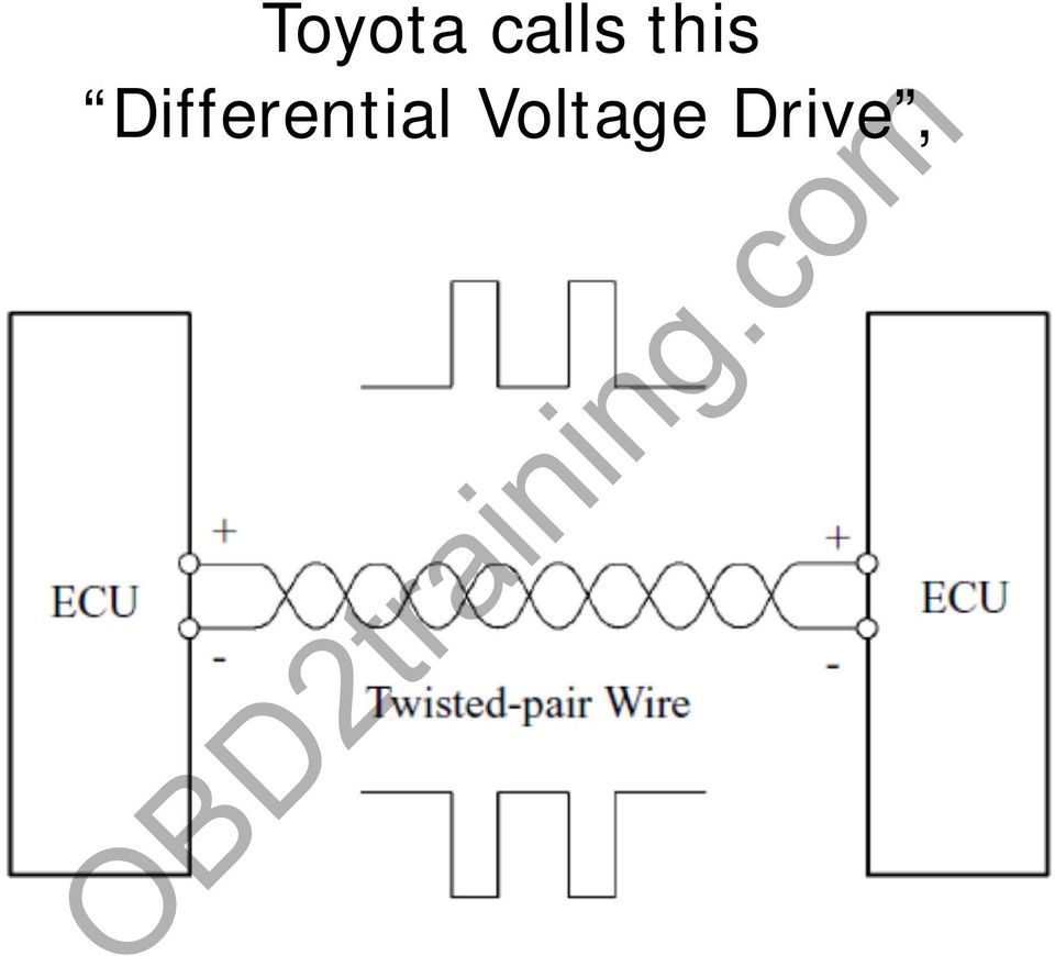
21 Class C CAN signal
22
23
24 What are Terminating Resistors Resistors are used to keep the load and signal reflections in check. Class C-CAN requires 120 ohm resistors on each line. The values specs are 120 ohms +/- 10% If the impedance is not even the signal could be unstable and not have the proper signal for good communications.
25 Terminating resistors -standing waves With terminating resistors
26 Terminating resistors -standing waves Without terminating resistors
27 External Terminating Resistors
28 Testing Termination 1. Turn off all power supplies of the attached CAN nodes. 2. Measure the resistance between CAN_H pin 6 and CAN_L pin 14 at the OBDll connector. The measured value should be between 60 Ω. The measured value should be nearly the same at each point of the network. If the value is below 60 Ω +/- 10% ( 48 Ω), make sure that: - there is no short circuit between CAN_H and CAN_L wiring - there are not more than two terminating resistors - the nodes do not have faulty transceivers. If the value is higher than 60 Ω +/- 10% (72 Ω), make sure that: - there are no open circuits in CAN_H or CAN_L wiring - your bus system has two terminating resistors (one at each end) and that they are 120 Ω each.
29 Code setting Corrupted messages are flagged by any node detecting an error. An error frame is transmitted to notify ECUs that errors have been detected, so that the ECUs ignore the message recently received.
30 Quick check of the CAN Bus To accurately diagnose CAN bus faults and system failures, all the modules on the vehicle should be checked for fault codes. Just checking a few modules can be misleading which could result in inaccurate diagnosis.
31 Error Management
32 Type of U and P codes Tattle-tailing on each other (the module doesn t know it has a problem) Module is not responding ( went dead) Internal issue with the module( wigs out, doesn t see other nodes) A receive/send module failure ( it is the only node on the bus without a code, and may not be able to code)
33 Diagnosing CAN faults Most U codes usually are designated by SAE. (see handout) INTEL/Bosch faults are normally Manufacturer specific.
34 INTEL/Bosch faults These are basic codes related to CAN failures. Time out error- sporadic Bus failure CAN Bus off- current, unable to communicate on the BUS circuit CAN time out- persistent BUS failure CAN signal error- corrupted message, unclean signal CAN wrong message the receiving module has a conflict information between two different modules CAN message failure digital signal may not be clean or the sending Node did not send the proper message
35 Case Studies
36 Typical Mazda Topology
37 Code U0101 U0121 U0155 U0140 P0606 P061B U0401 U2023 U0401 Module PCM ABS TCM 2011 CX7 Description Lost Communication with TCM Lost Communication With Anti Lock Brake System (ABS) Control Module Lost Communication With Restraints Occupant Classification System Module Lost Communication With Body Control Module Invalid Data Received From ECM/PCM "A" Invalid Data Received From ECM/PCM "A" These were the only codes in the systems. MIL was on. The PCM was the problem. It was stating that it could not see any of the modules listed, yet the other modules did not have a communications problems. The PCM had an internal problem that it was unable to see the other modules.
38 Mazda CX5 Codes Module Description U3003 attery voltage U0121 Lost Communication With Anti Lock Brake System EPS (ABS) Control Module U0401 Invalid Data Received From ECM/PCM "A" U2005 U0121 U0155 U0121 U0100 U0121 U3004 U0121 Front body module Cluster PCM SSU TCM Lost Communication With Anti Lock Brake System (ABS) Control Module Lost Communication With Instrument Panel Cluster (IPC) Control Module Lost Communication With Anti Lock Brake System (ABS) Control Module Lost Communication With ECM/PCM "A" Lost Communication With Anti Lock Brake System (ABS) Control Module Accessory Power Relay Lost Communication With Anti Lock Brake System (ABS) Control Module All these modules are tattle tailing on one module, the ABS module. All malfunction indicators on the dash were on. DCS/Trac lights were flashing.
39 2011 Mazda 3 Code Module Description U3003 ABS Battery Voltage U0401 BCM Invalid Data Received From TCM U0001 High Speed CAN Communication Bus U0121 U0402 U0515 U2005 U3003 U0423 U0121 P061b Instrument Cluster module MID is the multifunction indicator in the center of the dash, used for outside temperature and calculate fuel economy PCM Lost Communication With Anti Lock Brake System (ABS) Control Module Invalid Data Received From TCM Invalid Data Received From Remote Function Actuation Battery Voltage Invalid Data Received From Instrument Panel Cluster Control Module Lost Communication With Anti Lock Brake System (ABS) Control Module The problem was the ABS module. It was taking down the bus. The modules codes because they needed the vehicle speed for calculations. The cluster needed it for the odometer, the MID needed it for instantaneous fuel average, the PCM needed it for the transmission torque calculations.
40 2012 Mazda3 Code Module Description U0001 High Speed CAN Communication Bus U0100 Lost Communication With ECM/PCM "A" U0101 Lost Communication with TCM U0140 ABS module Lost Communication With Body Control Module U0155 Lost Communication With Instrument Panel Cluster (IPC) Control Module U0428 Invalid Data Received From Steering Angle Sensor Module C0031 P1536. P1126. U0101 BCM Lost Communication with TCM U0151 Lost Communication With Restraints Control Module U0401 Invalid Data Received From ECM/PCM "A" U0073 U0100 TCM U0121 U0415 U0073 U0100 Control Module Communication Bus "A" Off Lost Communication With ECM/PCM "A" Lost Communication With Anti Lock Brake System (ABS) Control Module Invalid Data Received From Anti Lock Brake System (ABS) Control Module Control Module Communication Bus "A" Off Lost Communication With ECM/PCM "A" U0121 TCM Lost Communication With Anti Lock Brake System (ABS) Control Module U0415 Invalid Data Received From Anti Lock Brake System (ABS) Control Module U0001 High Speed CAN Communication Bus U0415 U2005 U3003 C0077 U0073 U0101 U0121 U0155 Invalid Data Received From Anti Lock Brake System (ABS) Control Module Instrument Cluster Battery Voltage Control Module Communication Bus "A" Off Lost Communication with TCM PCM Lost Communication With Anti Lock Brake System (ABS) Control Module Lost Communication With Instrument Panel Cluster (IPC) Control Module There were no codes in the EPHAS {electronic power steering module}. The EPHAS module was the problem
41 2011 CX7 Code Module Description U0101 U0121 U0155 U0140 P0606 P061B U0401 U2023 PCM ABS Lost Communication with TCM Lost Communication With Anti Lock Brake System (ABS) Control Module Lost Communication With Restraints Occupant Classification System Module Lost Communication With Body Control Module Invalid Data Received From ECM/PCM "A" U0401 TCM Invalid Data Received From ECM/PCM "A" These were the only codes in the systems. MIL was on. The PCM was the problem. It was stating that it could not see any of the modules listed, yet the other modules did not have a communications problems. The PCM had an internal problem that it was unable to see the other modules.
42 Typical Lexus Topology
43 Typical Lexus Topology Toyota 2013 GS350 1 ECM 2 Parking Brake ECU 3 Main body ECU 4 Brake Actuator Assembly 5 Combination Meter Assembly 6 DLC3 7 Head light Swivel ECU - AFS 8 Network Gateway ECU 9 Air Condition Amplifier Assembly 10 Spiral with Sensor Cable - Steering Angle Sensor 11 Yaw rate sensor 12 Multi-media module receiver 13 Power steering ECU 14 Center Airbag sensor assembly 15 Front steering Control ECU 16 Certification ECU-Smart Key
44 2013 Lexus GS350 Code Module Description P1604 ENGINE & ECT U0100 U0123 U0124 U0126 ABS/VSC/TRAC Lost Communication With ECM/PCM "A" Lost Communication With Yaw Rate Sensor Module Lost Communication With Lateral Acceleration Sensor Module Lost Communication With Steering Angle Sensor Module U0129 EMPS Lost Communication With Brake System Control Module U0073 U0124 U0129 U0100 U0131 U0142 U0155 U0163 U0100 U0129 U0131 U0142 U0151 U0100 U0101 U0120 U0151 U0155 U0164 U0182 U0327 U1106 U0100 U0142 U0155 U0100 U0129 U0142 U0101 U0155 U0100 U0140 U0155 Electronic Parking Brake Air conditioner Combination meter Main body module Smart Access AFS Auto Intuitive P/A Park assess Power Source Control Control Module Communication Bus "A" Off Lost Communication With Lateral Acceleration Sensor Module Lost Communication With Brake System Control Module Lost Communication With ECM/PCM "A" Lost Communication With Power Steering Control Module Lost Communication With Body Control Module "B" Lost Communication With Instrument Panel Cluster (IPC) Control Module Lost Communication With Navigation Control Module Lost Communication With ECM/PCM "A" Lost Communication With Brake System Control Module Lost Communication With Power Steering Control Module Lost Communication With Body Control Module Lost Communication With Restraints Control Module Lost Communication With ECM/PCM "A" Lost Communication with TCM Lost Communication With Starter / Generator Control Module Lost Communication With Restraints Control Module Lost Communication With Instrument Panel Cluster (IPC) Control Module Lost Communication With HVAC Control Module Lost Communication With Lighting Control Module Front Software Incompatibility With Vehicle Security Control Module Lost Communication With ECM/PCM "A" Lost Communication With Body Control Module "B" Lost Communication With Instrument Panel Cluster (IPC) Control Module Lost Communication With ECM/PCM "A" Lost Communication With Brake System Control Module Lost Communication With Body Control Module "B" Lost Communication with TCM Lost Communication With Instrument Panel Cluster (IPC) Control Module Lost Communication With ECM/PCM "A" Lost Communication With Body Control Module Lost Communication With Instrument Panel Cluster (IPC) Control Module After looking at all the codes and looking at the topology, the modules were all telling on each other except for one module. The radio head is a receive only module and has no capability for codes. When the vehicle sat in the sun, the hard drive in the radio head shorted the Bus, which caused all the codes and the vehicle to have no AC or navigation operation. Because the module is a receive only module, it was not capable of codes.
45 This concludes the presentation. Questions? Thank you
46 List modules on the CAN bus. In the blue boxes list the modules that have terminating
47 NETWORK SYSTEMS U00XX NETWORK ELECTRICAL U0001 High Speed CAN Communication Bus U0002 High Speed CAN Communication Bus Performance U0003 High Speed CAN Communication Bus (+) Open U0004 High Speed CAN Communication Bus (+) Low U0005 High Speed CAN Communication Bus (+) High U0006 High Speed CAN Communication Bus (-) Open U0007 High Speed CAN Communication Bus (-) Low U0008 High Speed CAN Communication Bus (-) High U0009 High Speed CAN Communication Bus (-) shorted to Bus (+) U0010 Medium Speed CAN Communication Bus U0011 Medium Speed CAN Communication Bus Performance U0012 Medium Speed CAN Communication Bus (+) Open U0013 Medium Speed CAN Communication Bus (+) Low U0014 Medium Speed CAN Communication Bus (+) High U0015 Medium Speed CAN Communication Bus (-) Open U0016 Medium Speed CAN Communication Bus (-) Low U0017 Medium Speed CAN Communication Bus (-) High U0018 Medium Speed CAN Communication Bus (-) shorted to Bus (+) U0019 Low Speed CAN Communication Bus U0020 Low Speed CAN Communication Bus Performance U0021 Low Speed CAN Communication Bus (+) Open U0022 Low Speed CAN Communication Bus (+) Low U0023 Low Speed CAN Communication Bus (+) High U0024 Low Speed CAN Communication Bus (-) Open U0025 Low Speed CAN Communication Bus (-) Low U0026 Low Speed CAN Communication Bus (-) High U0027 Low Speed CAN Communication Bus (-) shorted to Bus (+) U0028 Vehicle Communication Bus A U0029 Vehicle Communication Bus A Performance U0030 Vehicle Communication Bus A (+) Open U0031 Vehicle Communication Bus A (+) Low U0032 Vehicle Communication Bus A (+) High U0033 Vehicle Communication Bus A (-) Open U0034 Vehicle Communication Bus A (-) Low U0035 Vehicle Communication Bus A (-) High U0036 Vehicle Communication Bus A (-) shorted to Bus A (+) U0037 Vehicle Communication Bus B U0038 Vehicle Communication Bus B Performance U0039 Vehicle Communication Bus B (+) Open U0040 Vehicle Communication Bus B (+) Low
48 U0041 Vehicle Communication Bus B (+) High U0042 Vehicle Communication Bus B (-) Open U0043 Vehicle Communication Bus B (-) Low U0044 Vehicle Communication Bus B (-) High U0045 Vehicle Communication Bus B (-) shorted to Bus B (+) U0046 Vehicle Communication Bus C U0047 Vehicle Communication Bus C Performance U0048 Vehicle Communication Bus C (+) Open U0049 Vehicle Communication Bus C (+) Low U0050 Vehicle Communication Bus C (+) High U0051 Vehicle Communication Bus C (-) Open U0052 Vehicle Communication Bus C (-) Low U0053 Vehicle Communication Bus C (-) High U0054 Vehicle Communication Bus C (-) shorted to Bus C (+) U0055 Vehicle Communication Bus D U0056 Vehicle Communication Bus D Performance U0057 Vehicle Communication Bus D (+) Open U0058 Vehicle Communication Bus D (+) Low U0059 Vehicle Communication Bus D (+) High U0060 Vehicle Communication Bus D (-) Open U0061 Vehicle Communication Bus D (-) Low U0062 Vehicle Communication Bus D (-) High U0063 Vehicle Communication Bus D (-) shorted to Bus D (+) U0064 Vehicle Communication Bus E U0065 Vehicle Communication Bus E Performance U0066 Vehicle Communication Bus E (+) Open U0067 Vehicle Communication Bus E (+) Low U0068 Vehicle Communication Bus E (+) High U0069 Vehicle Communication Bus E (-) Open U0070 Vehicle Communication Bus E (-) Low U0071 Vehicle Communication Bus E (-) High U0072 Vehicle Communication Bus E (-) shorted to Bus E (+) U0073 Control Module Communication Bus "A" Off U0074 Control Module Communication Bus "B" Off U01XX NETWORK COMMUNICATION U0100 Lost Communication With ECM/PCM "A" U0101 Lost Communication with TCM U0102 Lost Communication with Transfer Case Control Module U0103 Lost Communication With Gear Shift Control Module "A" U0104 Lost Communication With Cruise Control Module U0105 Lost Communication With Fuel Injector Control Module U0106 Lost Communication With Glow Plug Control Module U0107 Lost Communication With Throttle Actuator Control Module U0108 Lost Communication With Alternative Fuel Control Module U0109 Lost Communication With Fuel Pump Control Module
49 U010A Lost Communication With Exhaust Gas Recirculation Control Module "A" U010B Lost Communication With Exhaust Gas Recirculation Control Module "B" U010C Lost Communication With Turbocharger/Supercharger Control Module "A" U010D Lost Communication With Turbocharger/Supercharger Control Module "B" U010E Lost Communication With Reductant Control Module U010F Lost Communication With Air Conditioning Control Module U0110 Lost Communication With Drive Motor Control Module "A" U0111 Lost Communication With Battery Energy Control Module "A" U0112 Lost Communication With Battery Energy Control Module "B" U0113 Lost Communication With Emissions Critical Control Information U0114 Lost Communication With Four-Wheel Drive Clutch Control Module U0115 Lost Communication With ECM/PCM "B" U0116 Lost Communication With Coolant Temperature Control Module U0117 Lost Communication With PTO Control Module U0118 Lost Communication With Fuel Additive Control Module U0119 Lost Communication With Fuel Cell Control Module U011A Lost Communication With Exhaust Gas Sensor Module U011B Lost Communication With Rocker Arm Control Module "A" U011C Lost Communication With Rocker Arm Control Module "B" U011D Lost Communication With All Wheel Drive Control Module U0120 Lost Communication With Starter / Generator Control Module U0121 Lost Communication With Anti-Lock Brake System (ABS) Control Module U0122 Lost Communication With Vehicle Dynamics Control Module U0123 Lost Communication With Yaw Rate Sensor Module U0124 Lost Communication With Lateral Acceleration Sensor Module U0125 Lost Communication With Multi-axis Acceleration Sensor Module U0126 Lost Communication With Steering Angle Sensor Module U0127 Lost Communication With Tire Pressure Monitor Module U0128 Lost Communication With Park Brake Control Module U0129 Lost Communication With Brake System Control Module U0130 Lost Communication With Steering Effort Control Module U0131 Lost Communication With Power Steering Control Module U0132 Lost Communication With Suspension Control Module "A" U0133 Lost Communication With Active Roll Control Module U0134 Lost Communication With Power Steering Control Module Rear U0135 Lost Communication With Differential Control Module Front U0136 Lost Communication With Differential Control Module Rear U0137 Lost Communication With Trailer Brake Control Module U0138 Lost Communication With All Terrain Control Module U0139 Lost Communication With Suspension Control Module "B" U0140 Lost Communication With Body Control Module U0141 Lost Communication With Body Control Module "A" U0142 Lost Communication With Body Control Module "B" U0143 Lost Communication With Body Control Module "C" U0144 Lost Communication With Body Control Module "D" U0145 Lost Communication With Body Control Module "E" U0146 Lost Communication With Gateway "A" U0147 Lost Communication With Gateway "B" U0148 Lost Communication With Gateway "C" U0149 Lost Communication With Gateway "D" U0150 Lost Communication With Gateway "E" U0151 Lost Communication With Restraints Control Module U0152 Lost Communication With Side Restraints Control Module Left U0153 Lost Communication With Side Restraints Control Module Right U0154 Lost Communication With Restraints Occupant Classification System Module U0155 Lost Communication With Instrument Panel Cluster (IPC) Control Module U0156 Lost Communication With Information Center "A"
50 U0157 Lost Communication With Information Center "B" U0158 Lost Communication With Head Up Display U0159 Lost Communication With Parking Assist Control Module "A" U0160 Lost Communication With Audible Alert Control Module U0161 Lost Communication With Compass Module U0162 Lost Communication With Navigation Display Module U0163 Lost Communication With Navigation Control Module U0164 Lost Communication With HVAC Control Module U0165 Lost Communication With HVAC Control Module Rear U0166 Lost Communication With Auxiliary Heater Control Module U0167 Lost Communication With Vehicle Immobilizer Control Module U0168 Lost Communication With Vehicle Security Control Module U0169 Lost Communication With Sunroof Control Module U016A Lost Communication With Global Positioning System Module U0170 Lost Communication With "Restraints System Sensor A" U0171 Lost Communication With "Restraints System Sensor B" U0172 Lost Communication With "Restraints System Sensor C" U0173 Lost Communication With "Restraints System Sensor D" U0174 Lost Communication With "Restraints System Sensor E" U0175 Lost Communication With "Restraints System Sensor F" U0176 Lost Communication With "Restraints System Sensor G" U0177 Lost Communication With "Restraints System Sensor H" U0178 Lost Communication With "Restraints System Sensor I" U0179 Lost Communication With "Restraints System Sensor J" U017A Lost Communication With "Restraints System Sensor K" U017B Lost Communication With "Restraints System Sensor L" U017C Lost Communication With "Restraints System Sensor M" U017D Lost Communication With "Restraints System Sensor N" U017E Lost Communication With Seatbelt Pretensioner Module "A" U017F Lost Communication With Seatbelt Pretensioner Module "B" U0180 Lost Communication With Automatic Lighting Control Module U0181 Lost Communication With Headlamp Leveling Control Module U0182 Lost Communication With Lighting Control Module Front U0183 Lost Communication With Lighting Control Module Rear "A" U0184 Lost Communication With Radio U0185 Lost Communication With Antenna Control Module U0186 Lost Communication With Audio Amplifier "A" U0187 Lost Communication With Digital Disc Player/Changer Module "A" U0188 Lost Communication With Digital Disc Player/Changer Module "B" U0189 Lost Communication With Digital Disc Player/Changer Module "C" U0190 Lost Communication With Digital Disc Player/Changer Module "D" U0191 Lost Communication With Television U0192 Lost Communication With Personal Computer U0193 Lost Communication With "Digital Audio Control Module A" U0194 Lost Communication With "Digital Audio Control Module B" U0195 Lost Communication With Subscription Entertainment Receiver Module U0196 Lost Communication With Entertainment Control Module Rear "A" U0197 Lost Communication With Telephone Control Module U0198 Lost Communication With Telematic Control Module U0199 Lost Communication With "Door Control Module A"
51 U02XX NETWORK COMMUNICATION U0200 Lost Communication With "Door Control Module B" U0201 Lost Communication With "Door Control Module C" U0202 Lost Communication With "Door Control Module D" U0203 Lost Communication With "Door Control Module E" U0204 Lost Communication With "Door Control Module F" U0205 Lost Communication With "Door Control Module G" U0206 Lost Communication With Folding Top Control Module U0207 Lost Communication With Moveable Roof Control Module U0208 Lost Communication With "Seat Control Module A" U0209 Lost Communication With "Seat Control Module B" U0210 Lost Communication With "Seat Control Module C" U0211 Lost Communication With "Seat Control Module D" U0212 Lost Communication With Steering Column Control Module U0213 Lost Communication With Mirror Control Module U0214 Lost Communication With Remote Function Actuation U0215 Lost Communication With "Door Switch A" U0216 Lost Communication With "Door Switch B" U0217 Lost Communication With "Door Switch C" U0218 Lost Communication With "Door Switch D" U0219 Lost Communication With "Door Switch E" U0220 Lost Communication With "Door Switch F" U0221 Lost Communication With "Door Switch G" U0222 Lost Communication With "Door Window Motor A" U0223 Lost Communication With "Door Window Motor B" U0224 Lost Communication With "Door Window Motor C" U0225 Lost Communication With "Door Window Motor D" U0226 Lost Communication With "Door Window Motor E" U0227 Lost Communication With "Door Window Motor F" U0228 Lost Communication With "Door Window Motor G" U0229 Lost Communication With Heated Steering Wheel Module U0230 Lost Communication With Rear Gate Module U0231 Lost Communication With Rain Sensing Module U0232 Lost Communication With Side Obstacle Detection Control Module Left U0233 Lost Communication With Side Obstacle Detection Control Module Right U0234 Lost Communication With Convenience Recall Module U0235 Lost Communication With Cruise Control Front Distance Range Sensor Single Sensor or Center U0236 Lost Communication With Column Lock Module U0237 Lost Communication With "Digital Audio Control Module C" U0238 Lost Communication With "Digital Audio Control Module D" U0239 Lost Communication With Entrapment Control Module "A" U023A Lost Communication With Image Processing Module "A" U023B Lost Communication With Image Processing Module "B" U023C Lost Communication With Image Processing Module "C" U023D Lost Communication With Cruise Control Front Distance Range Sensor Left U023E Lost Communication With Cruise Control Front Distance Range Sensor Right U0240 Lost Communication With Entrapment Control Module "B" U0241 Lost Communication With Headlamp Control Module "A" U0242 Lost Communication With Headlamp Control Module "B" U0243 Lost Communication With Parking Assist Control Module "B" U0244 Lost Communication With Running Board Control Module "A"
52 U0245 Lost Communication With Entertainment Control Module Front U0246 Lost Communication With "Seat Control Module E" U0247 Lost Communication With "Seat Control Module F" U0248 Lost Communication With Remote Accessory Module U0249 Lost Communication With Entertainment Control Module Rear "B" U024A Lost Communication With Interior Lighting Control Module U0250 Lost Communication With Impact Classification System Module U0251 Lost Communication With Running Board Control Module "B" U0252 Lost Communication With Lighting Control Module Rear "B" U0253 Lost Communication With Accessory Protocol Interface Module U0254 Lost Communication With Remote Start Module U0255 Lost Communication With Front Display Interface Module U0256 Lost Communication With Front Controls Interface Module "A" U0257 Lost Communication With Front Controls/Display Interface Module U0258 Lost Communication With Radio Transceiver U0259 Lost Communication With Special Purpose Vehicle Control Module "A" U025A Lost Communication With Special Purpose Vehicle Control Module "B" U025B Lost Communication With Special Purpose Vehicle Control Module "C" U025C Lost Communication With Special Purpose Vehicle Control Module "D" U025D Lost Communication With Front Controls Interface Module "B" U0260 Lost Communication With Seat Control Switch Module "A" U0261 Lost Communication With Seat Control Switch Module "B" U0262 Lost Communication With Audio Amplifier "B" U0263 Lost Communication With Speech Recognition Module U0264 Lost Communication With Camera Module Rear U0286 Lost Communication With Radiator Anti tamper Device U0287 Lost Communication With Transmission Fluid Pump Module U0288 Lost Communication With DC to AC Converter Control Module "A" U0289 Lost Communication With DC to AC Converter Control Module "B" U0291 Lost Communication With Gear Shift Control Module "B" U0292 Lost Communication With Drive Motor Control Module "B" U0293 Lost Communication With Hybrid Powertrain Control Module U0294 Lost Communication With Powertrain Control Monitor Module U0295 Lost Communication With AC to AC Converter Control Module U0296 Lost Communication With AC to DC Converter Control Module "A" U0297 Lost Communication With AC to DC Converter Control Module "B" U0298 Lost Communication With DC to DC Converter Control Module "A" U0299 Lost Communication With DC to DC Converter Control Module "B" U029A Lost Communication With Hybrid Battery Pack Sensor Module U029B Lost Communication With Drive Motor Control Module "C" U029C Lost Communication With Drive Motor Control Module "D" U029D Lost Communication With NOX Sensor "A" U029E Lost Communication With NOX Sensor "B"
53 U03XX NETWORK SOFTWARE U0300 Internal Control Module Software Incompatibility U0301 Software Incompatibility With ECM/PCM U0302 Software Incompatibility With Transmission Control Module U0303 Software Incompatibility With Transfer Case Control Module U0304 Software Incompatibility With Gear Shift Control Module "A" U0305 Software Incompatibility With Cruise Control Module U0306 Software Incompatibility With Fuel Injector Control Module U0307 Software Incompatibility With Glow Plug Control Module U0308 Software Incompatibility With Throttle Actuator Control Module U0309 Software Incompatibility With Alternative Fuel Control Module U0310 Software Incompatibility With Fuel Pump Control Module U0311 Software Incompatibility With Drive Motor Control Module U0312 Software Incompatibility With Battery Energy Control Module A U0313 Software Incompatibility With Battery Energy Control Module B U0314 Software Incompatibility With Four-Wheel Drive Clutch Control Module U0315 Software Incompatibility With Anti-Lock Brake System Control Module U0316 Software Incompatibility With Vehicle Dynamics Control Module U0317 Software Incompatibility With Park Brake Control Module U0318 Software Incompatibility With Brake System Control Module U0319 Software Incompatibility With Steering Effort Control Module U0320 Software Incompatibility With Power Steering Control Module U0321 Software Incompatibility With Suspension Control Module "A" U0322 Software Incompatibility With Body Control Module U0323 Software Incompatibility With Instrument Panel Control Module U0324 Software Incompatibility With HVAC Control Module U0325 Software Incompatibility With Auxiliary Heater Control Module U0326 Software Incompatibility With Vehicle Immobilizer Control Module U0327 Software Incompatibility With Vehicle Security Control Module U0328 Software Incompatibility With Steering Angle Sensor Module U0329 Software Incompatibility With Steering Column Control Module U0330 Software Incompatibility With Tire Pressure Monitor Module U0331 Software Incompatibility With Body Control Module "A" U0332 Software Incompatibility With Multi-axis Acceleration Sensor Module U0333 Software Incompatibility With Gear Shift Control Module "B" U0334 Software Incompatibility With Radio U0335 Software Incompatibility With Hybrid Battery Pack Sensor Module U0336 Software Incompatibility with Restraints Control Module
54 U04XX NETWORK DATA U0400 Invalid Data Received U0401 Invalid Data Received From ECM/PCM "A" U0402 Invalid Data Received From TCM U0403 Invalid Data Received From Transfer Case Control Module U0404 Invalid Data Received From Gear Shift Control Module "A" U0405 Invalid Data Received From Cruise Control Module U0406 Invalid Data Received From Fuel Injector Control Module U0407 Invalid Data Received From Glow Plug Control Module U0408 Invalid Data Received From Throttle Actuator Control Module U0409 Invalid Data Received From Alternative Fuel Control Module U040A Invalid Data Received From Air Conditioning Control Module U040B Invalid Data Received From Exhaust Gas Recirculation Control Module "A" U040C Invalid Data Received From Exhaust Gas Recirculation Control Module "B" U040D Invalid Data Received From Turbocharger/Supercharger Control Module "A" U040E Invalid Data Received From Turbocharger/Supercharger Control Module "B" U040F Invalid Data Received From Reductant Control Module U0410 Invalid Data Received From Fuel Pump Control Module U0411 Invalid Data Received From Drive Motor Control Module "A" U0412 Invalid Data Received From Battery Energy Control Module "A" U0413 Invalid Data Received From Battery Energy Control Module "B" U0414 Invalid Data Received From Four-Wheel Drive Clutch Control Module U0415 Invalid Data Received From Anti-Lock Brake System (ABS) Control Module U0416 Invalid Data Received From Vehicle Dynamics Control Module U0417 Invalid Data Received From Park Brake Control Module U0418 Invalid Data Received From Brake System Control Module U0419 Invalid Data Received From Steering Effort Control Module U041B Invalid Data Received From Exhaust Gas Sensor Module U041C Invalid Data Received From Rocker Arm Control Module "A" U041D Invalid Data Received From Rocker Arm Control Module "B" U041E Invalid Data Received From All Wheel Drive Control Module U0420 Invalid Data Received From Power Steering Control Module U0421 Invalid Data Received From Suspension Control Module "A" U0422 Invalid Data Received From Body Control Module U0423 Invalid Data Received From Instrument Panel Cluster Control Module U0424 Invalid Data Received From HVAC Control Module U0425 Invalid Data Received From Auxiliary Heater Control Module U0426 Invalid Data Received From Vehicle Immobilizer Control Module U0427 Invalid Data Received From Vehicle Security Control Module U0428 Invalid Data Received From Steering Angle Sensor Module U0429 Invalid Data Received From Steering Column Control Module U0430 Invalid Data Received From Tire Pressure Monitor Module U0431 Invalid Data Received From Body Control Module "A" U0432 Invalid Data Received From Multi-axis Acceleration Sensor Module U0433 Invalid Data Received From Cruise Control Front Distance Range Sensor Single Sensor or Center U0434 Invalid Data Received From Active Roll Control Module U0435 Invalid Data Received From Power Steering Control Module Rear U0436 Invalid Data Received From Differential Control Module Front U0437 Invalid Data Received From Differential Control Module Rear U0438 Invalid Data Received From Trailer Brake Control Module U0439 Invalid Data Received From All Terrain Control Module U043A Invalid Data Received From Suspension Control Module "B" U043B Invalid Data Received From Cruise Control Front Distance Range Sensor Left U043C Invalid Data Received From Cruise Control Front Distance Range Sensor Right
55 U0441 Invalid Data Received From Emissions Critical Control Information U0442 Invalid Data Received From ECM/PCM "B" U0443 Invalid Data Received From Body Control Module "B" U0444 Invalid Data Received From Body Control Module "C" U0445 Invalid Data Received From Body Control Module "D" U0446 Invalid Data Received From Body Control Module "E" U0447 Invalid Data Received From Gateway "A" U0448 Invalid Data Received From Gateway "B" U0449 Invalid Data Received From Gateway "C" U044A Invalid Data Received From Gateway "D" U0451 Invalid Data Received From Gateway "E" U0452 Invalid Data Received From Restraints Control Module U0453 Invalid Data Received From Side Restraints Control Module Left U0454 Invalid Data Received From Side Restraints Control Module Right U0455 Invalid Data Received From Restraints Occupant Classification System Module U0456 Invalid Data Received From Coolant Temperature Control Module U0457 Invalid Data Received From Information Center "A" U0458 Invalid Data Received From Information Center "B" U0459 Invalid Data Received From Head Up Display U045A Invalid Data Received From Parking Assist Control Module "A" U0461 Invalid Data Received From Audible Alert Control Module U0462 Invalid Data Received From Compass Module U0463 Invalid Data Received From Navigation Display Module U0464 Invalid Data Received From Navigation Control Module U0465 Invalid Data Received From PTO Control Module U0466 Invalid Data Received From HVAC Control Module Rear U0467 Invalid Data Received From Fuel Additive Control Module U0468 Invalid Data Received From Fuel Cell Control Module U0469 Invalid Data Received From Starter / Generator Control Module U046A Invalid Data Received From Sunroof Control Module U046B Invalid Data Received From Global Positioning System Module U0471 Invalid Data Received From "Restraints System Sensor A" U0472 Invalid Data Received From "Restraints System Sensor B" U0473 Invalid Data Received From "Restraints System Sensor C" U0474 Invalid Data Received From "Restraints System Sensor D" U0475 Invalid Data Received From "Restraints System Sensor E" U0476 Invalid Data Received From "Restraints System Sensor F" U0477 Invalid Data Received From "Restraints System Sensor G" U0478 Invalid Data Received From "Restraints System Sensor H" U0479 Invalid Data Received From "Restraints System Sensor I" U047A Invalid Data Received From "Restraints System Sensor J" U047B Invalid Data Received From "Restraints System Sensor K" U047C Invalid Data Received From "Restraints System Sensor L" U047D Invalid Data Received From "Restraints System Sensor M" U047E Invalid Data Received From "Restraints System Sensor N" U047F Invalid Data Received From Seatbelt Pretensioner Module "A" U0480 Invalid Data Received From Seatbelt Pretensioner Module "B" U0481 Invalid Data Received From Automatic Lighting Control Module U0482 Invalid Data Received From Headlamp Leveling Control Module U0483 Invalid Data Received From Lighting Control Module Front U0484 Invalid Data Received From Lighting Control Module Rear "A" U0485 Invalid Data Received From Radio U0486 Invalid Data Received From Antenna Control Module U0487 Invalid Data Received From Audio Amplifier "A" U0488 Invalid Data Received From Digital Disc Player/Changer Module "A" U0489 Invalid Data Received From Digital Disc Player/Changer Module "B"
56 U048A Invalid Data Received From Digital Disc Player/Changer Module "C" U0491 Invalid Data Received From Digital Disc Player/Changer Module "D" U0492 Invalid Data Received From Television U0493 Invalid Data Received From Personal Computer U0494 Invalid Data Received From "Digital Audio Control Module A" U0495 Invalid Data Received From "Digital Audio Control Module B" U0496 Invalid Data Received From Subscription Entertainment Receiver Module U0497 Invalid Data Received From Entertainment Control Module Rear "A" U0498 Invalid Data Received From Telephone Control Module U0499 Invalid Data Received From Telematic Control Module U049A Invalid Data Received From "Door Control Module A" U05XX NETWORK DATA U0500 ISO/SAE Reserved U0501 Invalid Data Received From "Door Control Module B" U0502 Invalid Data Received From "Door Control Module C" U0503 Invalid Data Received From "Door Control Module D" U0504 Invalid Data Received From "Door Control Module E" U0505 Invalid Data Received From "Door Control Module F" U0506 Invalid Data Received From "Door Control Module G" U0507 Invalid Data Received From Folding Top Control Module U0508 Invalid Data Received From Moveable Roof Control Module U0509 Invalid Data Received From "Seat Control Module A" U050A Invalid Data Received From "Seat Control Module B" U050B ISO/SAE Reserved U050C ISO/SAE Reserved U050D ISO/SAE Reserved U050E ISO/SAE Reserved U050F ISO/SAE Reserved U0510 ISO/SAE Reserved U0511 Invalid Data Received From "Seat Control Module C" U0512 Invalid Data Received From "Seat Control Module D" U0513 Invalid Data Received From Yaw Rate Sensor Module U0514 Invalid Data Received From Mirror Control Module U0515 Invalid Data Received From Remote Function Actuation U0516 Invalid Data Received From "Door Switch A" U0517 Invalid Data Received From "Door Switch B" U0518 Invalid Data Received From "Door Switch C" U0519 Invalid Data Received From "Door Switch D" U051A Invalid Data Received From "Door Switch E" U0521 Invalid Data Received From "Door Switch F" U0522 Invalid Data Received From "Door Switch G" U0523 Invalid Data Received From "Door Window Motor A" U0524 Invalid Data Received From "Door Window Motor B" U0525 Invalid Data Received From "Door Window Motor C" U0526 Invalid Data Received From "Door Window Motor D"
57 U0527 Invalid Data Received From "Door Window Motor E" U0528 Invalid Data Received From "Door Window Motor F" U0529 Invalid Data Received From "Door Window Motor G" U052A Invalid Data Received From Heated Steering Wheel Module U0531 Invalid Data Received From Rear Gate Module U0532 Invalid Data Received From Rain Sensing Module U0533 Invalid Data Received From Side Obstacle Detection Control Module Left U0534 Invalid Data Received From Side Obstacle Detection Control Module Right U0535 Invalid Data Received From Convenience Recall Module U0536 Invalid Data Received From Lateral Acceleration Sensor Module U0537 Invalid Data Received From Column Lock Module U0538 Invalid Data Received From "Digital Audio Control Module C" U0539 Invalid Data Received From "Digital Audio Control Module D" U053A Invalid Data Received From Entrapment Control Module "A" U053B Invalid Data Received From Image Processing Module "A" U053C Invalid Data Received From Image Processing Module "B" U053D Invalid Data Received From Image Processing Module "C" U0541 Invalid Data Received From Entrapment Control Module "B" U0542 Invalid Data Received From Headlamp Control Module "A" U0543 Invalid Data Received From Headlamp Control Module "B" U0544 Invalid Data Received From Parking Assist Control Module "B" U0545 Invalid Data Received From Running Board Control Module U0546 Invalid Data Received From Entertainment Control Module Front U0547 Invalid Data Received From "Seat Control Module E" U0548 Invalid Data Received From "Seat Control Module F" U0549 Invalid Data Received From Remote Accessory Module U054A Invalid Data Received From Entertainment Control Module Rear "B" U054B Invalid Data Received From Interior Lighting Control Module U0552 Invalid Data Received From Running Board Control Module "B" U0553 Invalid Data Received From Lighting Control Module Rear "B" U0554 Invalid Data Received From Accessory Protocol Interface Module U0555 Invalid Data Received From Remote Start Module U0556 Invalid Data Received From Front Display Interface Module U0557 Invalid Data Received From Front Controls Interface Module "A" U0558 Invalid Data Received From Front Controls/Display Interface Module U0559 Invalid Data Received From Radio Transceiver U055A Invalid Data Received From Special Purpose Vehicle Control Module "A" U055B Invalid Data Received From Special Purpose Vehicle Control Module "B" U055C Invalid Data Received From Special Purpose Vehicle Control Module "C" U055D Invalid Data Received From Special Purpose Vehicle Control Module "D" U055E Invalid Data Received From Front Controls Interface Module "B" U0561 Invalid Data Received From Seat Control Switch Module "A" U0562 Invalid Data Received From Seat Control Switch Module "B" U0563 Invalid Data Received From Audio Amplifier "B" U0564 Invalid Data Received From Speech Recognition Module U0565 Invalid Data Received From Camera Module Rear U0587 Invalid Data Received From With Radiator Anti Tamper Device U0588 Invalid Data Received From Transmission Fluid Pump Module U0589 Invalid Data Received From DC to AC Converter Control Module "A" U058A Invalid Data Received From DC to AC Converter Control Module "B" U0592 Invalid Data Received From Gear Shift Control Module "B" U0593 Invalid Data Received From Drive Motor Control Module "B" U0594 Invalid Data Received From Hybrid Powertrain Control Module U0595 Invalid Data Received From Powertrain Control Monitor Module U0596 Invalid Data Received From AC to AC Converter Control Module U0597 Invalid Data Received From AC to DC Converter Control Module "A"
58 U0598 Invalid Data Received From AC to DC Converter Control Module "B" U0599 Invalid Data Received From DC to DC Converter Control Module "A" U059A Invalid Data Received From DC to DC Converter Control Module "B" U059B Invalid Data Received From Hybrid Battery Pack Sensor Module U059C Invalid Data Received From Drive Motor Control Module "C" U059D Invalid Data Received From Drive Motor Control Module "D" U059E Invalid Data Received From NOX Sensor "A" U059F Invalid Data Received From NOX Sensor "B" U30XX CONTROL MODULE/POWER DISTRIBUTION U3000 Control Module U3001 Control Module Improper Shutdown U3002 Vehicle Identification Number U3003 Battery Voltage U3004 Accessory Power Relay U3005 Retained Accessory Power U3006 Control Module Input Power "A" U3007 Control Module Input Power "B" U3008 Control Module Ground "A" U3009 Control Module Ground "B" U300A Ignition Switch U300B Ignition Input Accessory/On/Start U300C Ignition Input Off/On/Start U300D Ignition Input On/Start U300E Ignition Input On U300F Ignition Input Accessory U3010 Ignition Input Start U3011 Ignition Input Off
ELECTRICAL WIRING (R.H. DRIVE VEHICLES)
") C-1 ELECTRICAL WIRING (R.H. DRIVE VEHICLES) CONTENTS GENERAL.......................... 3 WIRING HARNESS CONFIGURATION DIAGRAMS......................... 4 ENGINE COMPARTMENT................ 4 DASH PANEL...........................
C-1 ELECTRICAL WIRING (R.H. DRIVE VEHICLES) CONTENTS GENERAL.......................... 3 WIRING HARNESS CONFIGURATION DIAGRAMS......................... 4 ENGINE COMPARTMENT................ 4 DASH PANEL...........................
Hybrid System Overview
 1 Hybrid System Overview January 31, 2004 2 Chevrolet Silverado / GMC Sierra Models: Extended Cab Short Box, 2WD & 4WD Engine: VORTEC 5.3 Liter V-8 Transmission: 4-speed auto transmission Power: 295 hp
DTC Database (OBD-II Trouble Codes)
") Auto Consulting S.a.s di Cofano A. & C. Attrezzature diagnostiche Elaborazioni elettroniche Formazione tecnica DTC Database (OBD-II Trouble Codes) Definitions for generic powertrain diagnostic trouble
Auto Consulting S.a.s di Cofano A. & C. Attrezzature diagnostiche Elaborazioni elettroniche Formazione tecnica DTC Database (OBD-II Trouble Codes) Definitions for generic powertrain diagnostic trouble
Subaru Reference. This reference contains the following information: connector pinouts. connector pinouts
 Subject: Source: 1993 2010 Impreza, WRX, and Sti and 2002 07 Outback Sport ABS wiring diagrams, harness routing, and connector locations and pinouts Subaru service manuals This reference contains the following
Note: This information obtained from internet sources and not verified- use at your own risk!!!!
 Cummins Engine Diagnostic Fault Codes for 2003 and later engines (generally for 2004 and later Alpines; see page 13 for earlier engine diagnostic codes): Note: This information obtained from internet sources
AUTOBOSS V30 hand-held diagnostic tool developed for the European market - the true all-in-one scan tool. OEM COVERAGE FOR EUROPEAN/ASIAN/US VEHICLES
 AUTOBOSS V30 hand-held diagnostic tool developed for the European market - the true all-in-one scan tool. OEM COVERAGE FOR EUROPEAN/ASIAN/US VEHICLES Feature LARGE VGA COLOUR TOUCH SCREEN Software updates
G PART NUMBER OF CONNECTORS
 A 1 A/C Ambient Temp. Sensor 90980 11070 Buckle SW RH (w/ Power Seat) A/C Condenser Fan Motor (1G FE) 90980 10928 B 9 Buckle SW RH (w/o Power Seat) 90980 11212 A 2 A/C Condenser Fan Motor (2JZ GE) 90980
Controller Area Network CAN 507 HO CAN B (ICC)10-28-02
10-28-02") Controller Area Network CAN 507 HO CAN B (ICC)10-28-02 1 These technical training materials are current as of the date noted on the materials, and may be revised or updated without notice. Always check
Controller Area Network CAN 507 HO CAN B (ICC)10-28-02 1 These technical training materials are current as of the date noted on the materials, and may be revised or updated without notice. Always check
INSTRUMENT PANEL. 1995 Volvo 850 DESCRIPTION & OPERATION. 1995-96 ACCESSORIES & EQUIPMENT Volvo Instrument Panels
 INSTRUMENT PANEL 1995 Volvo 850 1995-96 ACCESSORIES & EQUIPMENT Volvo Instrument Panels 850 WARNING: When working around steering column and before performing repairs, disconnect and shield battery ground
6-years/75,000 miles Comprehensive coverage Subsequent Owner Warranty $100 Deductible
 LINCOLN PREMIER LIMITED WARRANTY 6-years/75,000 miles Comprehensive coverage Subsequent Owner Warranty $100 Deductible Comprehensive Coverage Because Lincoln has always been a brand you can trust and respect,
Introduction to Electronic Signals
 Introduction to Electronic Signals Oscilloscope An oscilloscope displays voltage changes over time. Use an oscilloscope to view analog and digital signals when required during circuit diagnosis. Fig. 6-01
Air conditioning, electrical testing
 just a test. Air conditioning, electrical testing 01-253 Wire and component test using VAG1598 A test box Special tools and equipment VAG 1598 A test box and VAG 1598/11 adapter cable and VAG 1598/12 VAG1526
AVL DISCAN 8000. Handheld-Scantool for multifunctional fields of application Faultcode-reader with integrated Informationsystem and Oscilloscope
 AVL DISCAN 8000 Handheld-Scantool for multifunctional fields of application Faultcode-reader with integrated Informationsystem and Oscilloscope Thomas Penz 26.11.2010 Seite 1 Content and Topics Description
In-Vehicle Networking
 In-Vehicle Networking SAE Network classification Class A networks Low Speed (
ECM Diagnosis. Section 11. Learning Objectives:
 Section 11 ECM Diagnosis Learning Objectives: 1. Diagnose ECM specific Diagnostic Trouble Codes. 2 Troubleshooting the diagnostic circuit. 3. Reprogramming the ECU. Engine Control Systems II - Course 874
Wynn s Extended Care
 Wynn s Extended Care Every car deserves to receive the very best care... especially yours. How Do You Keep Your Reliable Transportation Reliable? Count on Wynn s Because Wynn s has been caring for cars
Multi-information Display (see MID )
") Driving Position Memory (see Seats ) Power Mirrors (see Mirrors ) Indicators/Gauges (see Instrument Panel ) Multi-information Display (see MID ) HomeLink (see HomeLink ) Navigation System (see Navigation
Driving Position Memory (see Seats ) Power Mirrors (see Mirrors ) Indicators/Gauges (see Instrument Panel ) Multi-information Display (see MID ) HomeLink (see HomeLink ) Navigation System (see Navigation
Introduction. In this Self-study Programme we will explain to you the design and function of the CAN data bus. SSP 186/01
 Introduction The requirements relating to driving safety, driving comfort, exhaust emissions and fuel economy are are becoming ever more stringent. This entails more intensive information exchange between
Transporter Fitting Locations No. 804 / 1
 Page 1 of 10 Transporter Fitting Locations No. 804 / 1 Pin connector assigment of selected connections Overview: 1 - Ignition/starter switch -D- On steering column Connector assigment chapter 2 - Onboard
Touareg Component Locations No. 802 / 1
 Touareg Component Locations No. 802 / 1 1 Fuses 1.1 Fuses 1.1.1 Overview of Fuses 1 - Fuses (SB) on fuse panel B on left instrument panel Location page 3 Fuse Arrangements, from November 2006 page 4 2
ABS- 0011 Left front wheel sensor Faulty signal. ABS- 0012 Left front wheel sensor Faulty signal. ABS- 0022 Right front wheel sensor.
 ABS- 0010 Left front wheel sensor Signal missing. Permanent fault ABS- 0011 Left front wheel sensor Faulty signal ABS- 0012 Left front wheel sensor Faulty signal ABS- 0020 Right front wheel sensor. Signal
Automotive Architectures for Interior Electronics
 Automotive Architectures for Interior Electronics Disclaimer : Although every attempt has been made to make the information in this document as accurate as possible it is not guaranteed to be 100% accurate.
01-3 0000-00 6810-20 AIR CONDITIONING SYSTEM 1. FFH SPECIFICATION AIR CONDITIONING SYSTEM RODIUS 2004.09
 0000-00 01-3 6810-20 1. FFH SPECIFICATION 01-4 0000-00 2. SYSTEM LAYOUT AND COMPONENTS 0000-00 01-5 01-6 0000-00 3. FFH GENERAL INFORMATION The system is to increase the coolant temperature quickly by
LOCAL INTERCONNECT NETWORK (LIN)
") 54B-1 GROUP 54B LOCAL INTERCONNECT NETWORK (LIN) CONTENTS GENERAL INFORMATION 54B-2 SPECIAL TOOLS 54B-3 54B-4 DIAGNOSIS FUNCTION 54B-4 DIAGNOSTIC TROUBLE CODE CHART 54B-6 DIAGNOSTIC TROUBLE CODE PROCEDURES
54B-1 GROUP 54B LOCAL INTERCONNECT NETWORK (LIN) CONTENTS GENERAL INFORMATION 54B-2 SPECIAL TOOLS 54B-3 54B-4 DIAGNOSIS FUNCTION 54B-4 DIAGNOSTIC TROUBLE CODE CHART 54B-6 DIAGNOSTIC TROUBLE CODE PROCEDURES
Schematic - 379 Model Family Electrical P94-6023 C 01
 Schematic - 379 Model Family Electrical P94-6023 C 01 SH NO. TITLE 1) INDEX 2) ARCHITECTURE 85) ENGINE - CUM ISX ( BJ SERVICES ) ( CONTINUED ) 3) LOCATION OF MAJOR COMPONENTS 86) ENGINE ECU POWER 4) LOCATION
MINI EXTENDED SERVICE CONTRACTS
 MINI EXTENDED SERVICE CONTRACTS LESS WORRY, MORE WEEEE! CONTINUING COVERAGE FOR YOUR NEW, USED, OR CERTIFIED PRE-OWNED MINI. Whether your odometer is ticking toward the end of your original 4-year/50,000-mile
LOCAL INTERCONNECT NETWORK (LIN)
") 54B-1 GROUP 54B LOCAL INTERCONNECT NETWORK (LIN) CONTENTS GENERAL INFORMATION 54B-2 SPECIAL TOOLS 54B-3 54B-4 DIAGNOSIS FUNCTION 54B-4 DIAGNOSTIC TROUBLE CODE CHART 54B-5 DIAGNOSTIC TROUBLE CODE PROCEDURES
54B-1 GROUP 54B LOCAL INTERCONNECT NETWORK (LIN) CONTENTS GENERAL INFORMATION 54B-2 SPECIAL TOOLS 54B-3 54B-4 DIAGNOSIS FUNCTION 54B-4 DIAGNOSTIC TROUBLE CODE CHART 54B-5 DIAGNOSTIC TROUBLE CODE PROCEDURES
Signature and ISX CM870 Electronics
 Signature and ISX CM870 Electronics Cummins West Training Center System Description General Information The Signature and ISX CM870 engine control system is an electronically operated fuel control system
AUTOMOBILE MECHANIC STUDENT INTERNSHIP SKILLS LIST Provo School District
 AUTOMOBILE MECHANIC STUDENT INTERNSHIP SKILLS LIST Provo School District Repairs and overhauls automobiles, buses, trucks, and other automotive vehicles: Examines vehicle and discusses with customer or
VEHICLE THEFT/SECURITY SYSTEM
 PL VEHICLE THEFT/SECURITY SYSTEM 8Q - 1 VEHICLE THEFT/SECURITY SYSTEM TABLE OF CONTENTS page DESCRIPTION AND OPERATION INTRODUCTION...1 VEHICLE THEFT/SECURITY SYSTEM (VTSS)... 1 (SKIS)... 2 SENTRY KEY
ON-Board Diagnostic Trouble Codes
 ON-Board Diagnostic Trouble Codes The list below contains standard diagnostic trouble codes (DTC s) that are used by some manufacturers to identify vehicle problems. The codes provide below are generic
Electronic Power Control
 Service. Self-Study Programme 210 Electronic Power Control Design and Function With the Electronic Power Control system, the throttle valve is actuated only by an electric motor. This eliminates the need
PASSKEY NO-START DIAGNOSTICS COMMU BREAK
 PASSKEY NO-START DIAGNOSTICS COMMU BREAK 28 Motor Age June 2005 www.motorage.com NICATION DOWN When the engine in a GM vehicle won t start, better check the vehicle s Passkey system. Are you ready to tackle
CONTINUED COVERAGE FOR YOUR NEW, USED, OR CERTIFIED PRE-OWNED BMW.
 BMW EXTENDED SERVICE CONTRACTS FEEL THE RUSH OF ASSURANCE. CONTINUED COVERAGE FOR YOUR NEW, USED, OR CERTIFIED PRE-OWNED BMW. Whether your original 4-year/50,000-mile BMW Warranty is coming to an end,
COVERING MILLIONS Preferred Protection Plan, a Service Group Company www.sgifs.com PO Box 26830, Austin, TX 78755-0800.
 COVERING MILLIONS Preferred Protection Plan, a Service Group Company www.sgifs.com PO Box 26830, Austin, TX 78755-0800. 1-877-565-0816 PPP-308 0903 rev 0408 BENEFITS New and Pre-Owned Vehicles Preferred
A/C-HEATER SYSTEM - AUTOMATIC
 A/C-HEATER SYSTEM - AUTOMATIC 1995 Volvo 850 1995-96 Auto. A/C-Heater Systems Volvo 850 * PLEASE READ THIS FIRST * WARNING: To avoid injury from accidental air bag deployment, read and carefully follow
PLAN VEHICLE THE COST OF UNEXPECTED REPAIRS FREQUENTLY ASKED QUESTIONS PACKAGE PROTECTION
 Administered by GWC Warranty Corporation Showroom Level, 40 Coal Street Wilkes-Barre, PA 18702 1.800.482.7357 www.gwcwarranty.com This plan is backed by American Bankers Insurance Company of Florida (in
E - THEORY/OPERATION
 E - THEORY/OPERATION 1995 Volvo 850 1995 ENGINE PERFORMANCE Volvo - Theory & Operation 850 INTRODUCTION This article covers basic description and operation of engine performance-related systems and components.
ENGINE DIAGNOSTICS & CONTROL
 ENGINE DIAGNOSTICS & CONTROL CONTROL SYSTEM WIRING DIAGRAM Page 1 Page 2 MONITORING SYSTEM AND CONTROL SYSTEM DEVICE RELATIONSHIP CHART : Applicable Component Input Battery Ignition switch A/C switch,
PROCEDURES FOR SELF DIAGNOSTICS
 PROCEDURES FOR SELF DIAGNOSTICS Baum Tools Unlimited Inc. March 31, 1999 TAU 2.1 READING ACTUAL VALUES 1. Remove the operating console from the TAU 2. At the upper side of the operating consol there is
NETWORKS Controller Area Network (CAN)
") SEC TION 2 : DOMEST I C GMLAN Overview GMLAN is the General Motors variation of the CAN Bus. Although it is CAN based, there are enough proprietary features and functions to make this a unique protocol.
SEC TION 2 : DOMEST I C GMLAN Overview GMLAN is the General Motors variation of the CAN Bus. Although it is CAN based, there are enough proprietary features and functions to make this a unique protocol.
Electronic Diesel Control EDC 16
 Service. Self-Study Programme 304 Electronic Diesel Control EDC 16 Design and Function The new EDC 16 engine management system from Bosch has its debut in the V10-TDI- and R5-TDI-engines. Increasing demands
FAULT CODE READER OBD11 FOR PETROL ENGINES PART NO
 FAULT CODE READER OBD11 FOR PETROL ENGINES PART NO 77004 HANDBOOK FAULT CODE READER FOR PETROL ENGINES with OBD11 INDEX Page 1. Introduction 4 2. Instructions 5 3. Common Terms 6 4. Precautions 6 5. Fault
Porsche Approved Certified Pre-Owned. Limited Warranty
 Porsche Approved Certified Pre-Owned Limited Warranty Porsche Approved. A guaranteed mark of quality. At Porsche, we re committed to exceptional performance. The inherent reliability and longevity of
LOCAL INTERCONNECT NETWORK (LIN)
") 54B-1 GROUP 54B LOCAL INTERCONNECT NETWORK (LIN) CONTENTS GENERAL INFORMATION........ 54B-2............ 54B-3 STRUCTURE................... 54B-2 54B-2 LIN refers to "Local Interconnect Network," which
54B-1 GROUP 54B LOCAL INTERCONNECT NETWORK (LIN) CONTENTS GENERAL INFORMATION........ 54B-2............ 54B-3 STRUCTURE................... 54B-2 54B-2 LIN refers to "Local Interconnect Network," which
Introduction... 2. Body Specifications... 3. Technical Data... 4. Body... 5. Interior Rear Seats... 6. Center Arm Rest... 7. Child Seat Restraint...
 Table of Contents Subject Page Introduction.......................................... 2 Body Specifications.................................... 3 Technical Data........................................
Vehicle electrics in Polo Model Year 2002
 Service. Self-Study Programme 265 Vehicle electrics in Polo Model Year 2002 265_061 The range of electrical systems in new vehicles is expanding increasingly as a result of the ever more effective safety
VEHICLE THEFT/SECURITY SYSTEMS
 DN VEHICLE THEFT/SECURITY SYSTEMS 8Q - 1 VEHICLE THEFT/SECURITY SYSTEMS TABLE OF CONTENTS page GENERAL INFORMATION INTRODUCTION...1 VEHICLE THEFT SECURITY SYSTEM....1 ENABLING...1 ARMING...1 DISARMING...2
2009 QUICK REFERENCE GUIDE GET INFORMED. ROLL.
 xb 2009 QUICK REFERENCE GUIDE GET INFORMED. ROLL. 2009 Scion xb This Quick Reference Guide is a summary of basic vehicle operations. It contains brief descriptions of fundamental operations so you can
The Touareg Electrical System
 Service. Self-Study Programme 298 The Touareg Electrical System Design and Function Vehicles with off-road capability are no longer just utility vehicles for a limited group of people. At all levels in
Heater and Air Conditioner, Blend Air System, Troubleshooting 83.06
 A/C Performance Diagnosis Problem Warm Airflow When the Air Conditioner is On, A/C Not Working, or Poor A/C Performance (dash outlet temperature is too high) Problem Warm Airflow When the Air Conditioner
LOCAL INTERCONNECT NETWORK (LIN)
") 54B-1 GROUP 54B LOCAL INTERCONNECT NETWORK (LIN) CONTENTS SPECIAL TOOLS................ 54B-2............ 54B-3 DIAGNOSIS CODE CHART............ 54B-3 DIAGNOSIS FUNCTION............... 54B-4 DIAGNOSIS
54B-1 GROUP 54B LOCAL INTERCONNECT NETWORK (LIN) CONTENTS SPECIAL TOOLS................ 54B-2............ 54B-3 DIAGNOSIS CODE CHART............ 54B-3 DIAGNOSIS FUNCTION............... 54B-4 DIAGNOSIS
PEMS Conference. Acquiring Data from In-Vehicle Networks. Rick Walter, P.E. HEM Data Corporation
 PEMS Conference Acquiring Data from In-Vehicle Networks Rick Walter, P.E. HEM Data Corporation Acquiring Data from In-Vehicle Networks Topics Overview/Benefits Heavy Duty J1939 protocol Available J1939
Wiring diagrams 14 1. Component key for wiring diagrams 1 to 29 Note: Not all the items listed will be fitted to all models
 Wiring diagrams 14 1 Component key for wiring diagrams 1 to 29 Note: Not all the items listed will be fitted to all models No Description 00200 Alternator with built-in regulator 00500 Battery 01001 Starter
CONTINUOUSLY VARIABLE TRANSMISSION (CVT)
") GROUP 23 CONTINUOUSLY VARIABLE TRANSMISSION (CVT) CONTENTS CVT........................... 23-2 GENERAL INFORMATION............. 23-2 ELECTRONIC CONTROL SYSTEM...... 23-3 EEPROM...........................
GROUP 23 CONTINUOUSLY VARIABLE TRANSMISSION (CVT) CONTENTS CVT........................... 23-2 GENERAL INFORMATION............. 23-2 ELECTRONIC CONTROL SYSTEM...... 23-3 EEPROM...........................
Table of Contents. Introducing AYGO. Accessing your vehicle 2 3. Lights 9. Wipers 10. Electric windows 4. Gear change 11
 AYGO Brief Guide Table of Contents Accessing your vehicle 2 3 Electric windows 4 Steering wheel (Vehicles with an adjustable type) 4 Seat and seat belt adjustment 5 Instrument Panel overview 6 Instrument
The Crafter Electrical system
 Service Training Self-study Programme 370 Commercial Vehicles The Crafter Electrical system Design and function Innovations in automotive engineering are also taking place in the commercial vehicle segment.
Meritor WABCO Pneumatic Antilock Braking System (ABS) 42.22
 42.22") (ABS) 2.22 Troubleshooting WARNING Before testing a vehicle equipped with Automatic Traction Control (ATC) on a dynamometer, the ATC system must be disabled. See Subject 160 for instructions. Activation
(ABS) 2.22 Troubleshooting WARNING Before testing a vehicle equipped with Automatic Traction Control (ATC) on a dynamometer, the ATC system must be disabled. See Subject 160 for instructions. Activation
Technical Service Information
 Technical Service Information COMPLAINT: CAUSE: 1996-20 DEFINITIONS When a VW/Audi vehicle is exhibiting a symptom or is in fail-safe, the technician, in many cases, is unable to communicate with the on-board
Automotive Technician-Advanced
 Job Ready Assessment Blueprint Automotive Technician-Advanced Test Code: 4008 / Version: 01 Copyright 2006. All Rights Reserved. General Assessment Information Automotive Technician-Advanced Blueprint
Fault codes DM1. Industrial engines DC09, DC13, DC16. Marine engines DI09, DI13, DI16 INSTALLATION MANUAL. 03:10 Issue 5.0 en-gb 1
 Fault codes DM1 Industrial engines DC09, DC13, DC16 Marine engines DI09, DI13, DI16 03:10 Issue 5.0 en-gb 1 DM1...3 Abbreviations...3 Fault type identifier...3...4 03:10 Issue 5.0 en-gb 2 DM1 DM1 Fault
TOYOTA ELECTRONIC CONTROL TRANSMISSION
 Electronic Control Transmission (ECT) The Electronic Control Transmission is an automatic transmission which uses modern electronic control technologies to control the transmission. The transmission itself,
Electronically Controlled Air Suspension (ECAS) for Trucks
 for Trucks") $2.50 Electronically Controlled Air Suspension (ECAS) for Trucks Maintenance Manual No. 36 Issued 7-99 ECAS System for 6 x 2 and 6 x 4 Vehicles with Rear Air Suspensions Service Notes Service Notes This
$2.50 Electronically Controlled Air Suspension (ECAS) for Trucks Maintenance Manual No. 36 Issued 7-99 ECAS System for 6 x 2 and 6 x 4 Vehicles with Rear Air Suspensions Service Notes Service Notes This
Table of Contents. 1.what is OBD2. 2. Product Information. 1. Safety Precautions and Warnings 1. obd2 was developed by the Califrnia Air Resources
 Table of Contents 1. Safety Precautions and Warnings 1 2. General Information 2.1 On-Board-Diagnostics (OBD )II 2 2.2 Diagnostic Trouble Codes (DTCs) 2 2.3 Location of the Data Link Connector (DTC) 3 2.4
Transmission electronic controls outline. Inputs- processing- outputs
 Transmission electronic controls outline Inputs- processing- outputs Inputs provide the system the environmental conditions that are needed to operate or check the operation of the transmission. Inputs
1993 WIRING DIAGRAMS Volkswagen Wiring Diagrams. Volkswagen; EuroVan
 Article Text ARTICLE BEGINNING 1993 WIRING DIAGRAMS Volkswagen Wiring Diagrams Volkswagen; EuroVan COMPONENT LOCATION MENU COMPONENT LOCATIONS TABLE ÄÄÄÄÄÄÄÄÄÄÄÄÄÄÄÄÄÄÄÄÄÄÄÄÄÄÄÄÄÄÄÄÄÄÄÄÄÄÄÄÄÄÄÄÄÄÄÄÄÄÄÄÄÄÄÄÄÄÄÄÄÄÄÄÄ
ANTI-THEFT SYSTEM. 1995 Volvo 850 DESCRIPTION & OPERATION BASIC ALARM. 1995-96 ACCESSORIES & EQUIPMENT Volvo Anti-Theft Systems
 ANTI-THEFT SYSTEM 1995 Volvo 850 1995-96 ACCESSORIES & EQUIPMENT Volvo Anti-Theft Systems 850 DESCRIPTION & OPERATION WARNING: Deactivate air bag system before performing any service operation. For 1995
2001 Mercedes-Benz ML320
 MODEL IDENTIFICATION 2001-04 STARTING & CHARGING SYSTEMS Starters - 163 Chassis WARNING: Vehicles are equipped with air bag supplemental restraint system. Before attempting any repairs involving steering
Lotus Service Notes Section EMR
 ENGINE MANAGEMENT SECTION EMR Sub-Section Page Diagnostic Trouble Code List EMR.1 3 Component Function EMR.2 7 Component Location EMR.3 9 Diagnostic Guide EMR.4 11 CAN Bus Diagnostics; Lotus TechCentre
Important: Always perform the Diagnostic System Check - Vehicle prior to using this diagnostic procedure. P0106, P0107 P0107
 Page 1 of 5 DTC P0106 DTC Descriptor 2006 Pontiac GTO GTO (VIN V) Service Manual Document ID: 1417869 DTC P0106: Manifold Absolute Pressure (MAP) Sensor Diagnostic Fault Information Important: Always perform
i ChatterBox! Motorcycle Security
 i Before you Start the Installation * Please read this manual to become familiar with the requirements necessary to complete the installation. * Use a high quality multi-meter to test all wires before
CAN AND NETWORK COMMUNICATIONS
 49 CAN AND NETWORK COMMUNICATIONS Figure 49-1 Module communications makes controlling multiple electrical devices and accessories easier by utilizing simple low-current switches to signal another module,
LOCAL INTERCONNECT NETWORK (LIN)
") 54C-1 GROUP 54C LOCAL INTERCONNECT NETWORK (LIN) CONTENTS GENERAL INFORMATION...54C-2 SPECIAL TOOL...54C-3...54C-4 DIAGNOSTIC FUNCTION...54C-4 DIAGNOSTIC TROUBLE CODE CHART...54C-6 DIAGNOSTIC TROUBLE CODE
54C-1 GROUP 54C LOCAL INTERCONNECT NETWORK (LIN) CONTENTS GENERAL INFORMATION...54C-2 SPECIAL TOOL...54C-3...54C-4 DIAGNOSTIC FUNCTION...54C-4 DIAGNOSTIC TROUBLE CODE CHART...54C-6 DIAGNOSTIC TROUBLE CODE
Emissions Readiness Monitor Strategies
 Emissions Readiness Monitor Strategies A presentation by NYS DMV s Office of Clean Air for New York State Automobile Dealers Association 10/30/2012 1 What is the payoff for mastering readiness monitor
Service Information Trucks
 Service Information Trucks Group 28 Release2 Engine Control Module (ECM), Diagnostic Trouble Code (DTC), Guide 2010 Emissions CHU CXU GU TD 89047073 Foreword The descriptions and service procedures contained
KEYLESS ENTRY UPGRADE SECURITY SYSTEM for 2004 TOYOTA HIGHLANDER
 KEYLESS ENTRY UPGRADE SECURITY SYSTEM for 2004 TOYOTA HIGHLANDER DEALER SERVICE AND INSTALLATION MANUAL KIT NO. 00016-30915 Contents PARTS LIST... 2 PARTS ILLUSTRATIONS... 2 VEHICLE PREPARATION... 3 INSTALLING
Electrical/electronic components and installation locations
 Volkswagen Passat B5 - Electrical/electronic components and installation locations Page 1 / 24 45-3 Electrical/electronic components and installation locations ABS/EDL/ASR Bosch 5.3 ABS hydraulic unit
AUTOMATIC TRANSMISSION IN-CAR DIAGNOSTICS
 Learning Guide CHASSIS ELECTRICAL SPECIALIST AUTOMATIC TRANSMISSION IN-CAR DIAGNOSTICS COURSE NUMBER: C050-01 Notice Due to the wide range of vehicles makes and models, the information given during the
Extended Protection Plans for New and Pre-Owned Vehicles
 Extended Protection Plans for New and Pre-Owned Vehicles Extended Protection you can count on from Old Republic Insured Automotive Services, Inc. (ORIAS) Your vehicle is a major investment. Next to your
Electrical Circuit Theory
 Electrical Circuit Theory Learning Objectives: 1. Review the basic electrical concepts of voltage, amperage, and resistance. 2. Review the components of a basic automotive electrical circuit. 3. Introduce
Module 6 Engine Control Module (ECM)
") Module 6 Engine Control Module (ECM) Author: Grant Swaim E-mail: [email protected] URL: www.tech2tech.net Phone: (336) 632-9882 Fax: (336) 632-9688 Postal Address: Tech-2-Tech Website PO Box 18443 Greensboro,
Module 6 Engine Control Module (ECM) Author: Grant Swaim E-mail: [email protected] URL: www.tech2tech.net Phone: (336) 632-9882 Fax: (336) 632-9688 Postal Address: Tech-2-Tech Website PO Box 18443 Greensboro,
Octavia (1U) 17-Dashboard up to 00 identification Octavia (1U) 17-Dashboard up to 00 07 - Coding Octavia (1U) 17-Dashboard up to 00 10 - Adaptation
 17-Dashboard up to 00 identification Octavia (1U) 17-Dashboard up to 00 07 - Coding Octavia (1U) 17-Dashboard up to 00 10 - Adaptation") Octavia (1U) 17-Dashboard up to 00 identification Octavia (1U) 17-Dashboard up to 00 07 - Coding Octavia (1U) 17-Dashboard up to 00 10 - Adaptation Octavia (1U) 17-Dashboard from 01 identification Octavia
Octavia (1U) 17-Dashboard up to 00 identification Octavia (1U) 17-Dashboard up to 00 07 - Coding Octavia (1U) 17-Dashboard up to 00 10 - Adaptation Octavia (1U) 17-Dashboard from 01 identification Octavia
Service Manual Trucks
 Service Manual Trucks Group 36 Vehicle Electronic Control Unit (MID 144), Diagnostic Trouble Code (DTC), Guide From build date 1.2007 PV776-88951780 Foreword The descriptions and service procedures contained
INSTALLATION MANUAL 3RP / 5RP 4-BUTTON SERIES VEHICLE SECURITY SYSTEMS
 3RP / 5RP 4-BUTTON SERIES VEHICLE SECURITY SYSTEMS INSTALLATION MANUAL Before you begin the installation Read the INSTRUCTIONS! Always use a multi-meter when verifying vehicle wiring. Before mounting the
ENGINE CONTROLS AND FUEL SYSTEMS
 ENGINE CONTROLS AND FUEL SYSTEMS SPRING 2005 FORD VEHICLE COMPUTER RELEARN PROCEDURES Performing repairs or service on any of the following may require you to initiate a computer relearn procedure in order
Vario Tractors - Fault Codes. Faults. all Vario tractors Tractor / General system. EDC / EMR bus fault. Fault in ECU Programming errors in ECU.
 12/1999 f 1/58 Vario Tractors - Codes 0000 000001 Date Version Page Capitel Index Docu-No. FCT_InitPage 0.0.11 A021; A022 Id rief description Description Consequences Link FENDIAS / Note ECU, EDC; ECU,
Powertrain DTC Summaries EOBD
 Powertrain DTC Summaries Quick Reference Diagnostic Guide Jaguar XJ Range V6, V8 N/A and V8 SC 2003.5 Model Year Refer to pages 2 9 for important information regarding the use of Powertrain DTC Summaries.
APPENDIX D PUBLIC AWARENESS INFORMATION
 APPENDIX D PUBLIC AWARENESS INFORMATION READINESS FAILURE FACT SHEET Beginning December 2004, New York will implement a new motor vehicle emission testing program in 53 of New York s upstate counties,
Air Conditioning System
 Air Conditioning System 1 Chonan Technical Service Training Center Chonan Technical Service Training Center 2 Objectives To understand the components of air conditioning system. To understand the control
Model 124 Relay and Control Modules Locations. 00-B.2a
 00-B.2a Page No. Fig. No. K1/2 Overvoltage protection relay (87E/87L/30a, 9-pole) B.2/2 1 K2 Headlamp washer relay B.2/1 K3/1 Intake manifold preheater relay B.2/4 14 K5 Power seat relay B.2/1 K9 Auxiliary
REMOVAL AND INSTALLATION
 303-01C-1 REMOVAL AND INSTALLATION Engine Body On Special Tool(s) Adapter For 303-D043 303-D043-02 or equivalent Special Tool(s) 303-01C-1 Turbocharger Lifting Bracket 303-1266 Wrench, Fan Clutch Nut 303-214
LAND ROVER MANUAL CONTENTS APPLICATIONS GENERAL OPERATION SPECIAL FUNCTIONS REMOTE CONTROL PROGRAMMING
 LAND ROVER LAND ROVER MANUAL CONTENTS APPLICATIONS GENERAL OPERATION SPECIAL FUNCTIONS REMOTE CONTROL PROGRAMMING APPLICATIONS VEHICLE SYSTEM YEAR CABLE CLASSIC RANGE ROVER 10AS 95 ON ADC110-B DEFENDER
Heavy Duty Equipment Mechanic (Class Code 3743) Task List. Inspection and Diagnosis
 Task List. Inspection and Diagnosis") Heavy Duty Equipment Mechanic (Class Code 3743) Task List Inspection and Diagnosis In order to verify complaints and determine malfunctions a Heavy Duty Mechanic: 1. Reads operators written trouble reports,
Heavy Duty Equipment Mechanic (Class Code 3743) Task List Inspection and Diagnosis In order to verify complaints and determine malfunctions a Heavy Duty Mechanic: 1. Reads operators written trouble reports,
SAS light Check Engine Malfunction Indicator Lamp
 SAS light Check Engine Malfunction Indicator Lamp Here's how to do it: In car ECM Diagnostics/ECM Reset procedure: 1) Sit in the driver's seat. 2) Turn the ignition key to the ON position and wait three
Overview of European 2010 Release
 Overview of European 2010 Release This European update is a significant improvement to the European product in terms of coverage years and actuation and adjustment capability. The focus of this European
MOTOR VEHICLE MECHANIC REPAIR CATEGORIES
 Chapter 8: Motor Vehicle Mechanic Repair Categories Page 1 CHAPTER 8 MOTOR VEHICLE MECHANIC REPAIR CATEGORIES Section 8-1 REQUIREMENT Section 10 of the Motor Vehicle Service and Repair Act (MCL 257.1310)
TOYOTA ELECTRONIC TRANSMISSION CHECKS & DIAGNOSIS
 Checks and Adjustments The transmission requires regular maintenance intervals if it is to continue to operate without failure. As we discussed in previous sections, transmission fluid loses certain properties
SECTION 412-00 Climate Control System General Information and Diagnostics
 412-00-i Climate Control System General Information and Diagnostics 412-00-i SECTION 412-00 Climate Control System General Information and Diagnostics CONTENTS PAGE DIAGNOSIS AND TESTING Climate Control
Electronically Controlled Clutchless or Variable Drive Compressors
 Electronically Controlled Clutchless or Variable Drive Compressors On many new air conditioning systems, such as Lexus, Cadillac, Chrysler, and others, a new type of compressor has been fitted. There are
TSB #: 74 Date: 9/7/2013 HOLDEN VE/WM HVAC & A/C DIAGNOSTIC HINTS
 HOLDEN VE/WM HVAC & A/C DIAGNOSTIC HINTS TSB #: 74 Date: 9/7/2013 Initial Once Read: In this technical bulletin we have listed diagnostic advice relating to the Holden VE/WM HVAC & A/C system. This information