Body Builders Layout Book
|
|
|
- Karin French
- 8 years ago
- Views:
Transcription
1 INDEX 0 Page Customer Access Circuits General Information General Practices Addition of Lights or Electrical Devices ESeries Chassis Circuits Upfitter Switches Customer Access Circuits 80 Stripped Chassis Stripped Chassis Rear Frame Trailer Tow Wiring Dual Battery Schematics Customer Access Schematics Super Duty FSeries Customer Access Schematics 9

2 GENERAL PRACTICES ADDITION OF LIGHTS OR ELECTRICAL DEVICES 0 GENERAL INFORMATION Super Duty FSeries and selected ESeries Super Duty vehicles are equipped with a number of conveniently located electrical wiring taps. Most taps are fused, having locations under the instrument panel, in the engine compartment, and at the rear of the frame. Illustrations, schematics and a wiring harness for Trailer Tow is provided in a cardboard box shipped with each vehicle. The circuits at the rear of the frame are provided to support trailer wiring requirements or the Second Unit Body (SUB) additions. The ESeries and Super Duty FSeries Circuit charts have a brief description of each circuit function, wire gauge, color code and electrical schematic.. The Ford starting and the charging system should not be altered.. The completed vehicle total electrical load must not exceed the maximum output of the alternator.. Do not route or attach electrical wires to fuel lines.. Engine compartment wiring must not be rerouted in any manner.. The.L diesel engine requires two batteries wired in parallel for proper starting operation and must not be isolated. Do not modify the Glow Plugs Power Circuits.. Ford recommends that all additional underhood and underbody wiring: Be crosslinked polyethylene, or equivalent, high temperature insulation wire C [ F] minimum rating. Meet SAE specifications J8 type SXL, GXL or TXL. Meet SAE J type SGX or STX for battery cables. Be protected with nylon convoluted tubing. Be located so as to avoid or minimize restriction of airflow through the engine compartment, underbody and fuel system. Be of sufficient length to be properly routed, so as not to interfere with operating zones of such components as throttle or transmission linkage. Not be routed near the exhaust system or any other source of high heat; melted insulation can result in electrical shorts and system failure. Be routed away from hostile surfaces and sharp edges and be secured in its intended location. Be protected by rubber grommets when it passes through body or frame openings. Use customer access passthru circuits provided on Super Duty FSeries to avoid additional openings between passenger and engine compartments. Be protected from electrical shorts by fuses or circuit breakers. Be routed at least 8 mm [. in] away from engine.. Interior wiring not exposed to high temperatures may be SAE approved, general purpose wire. 8. Ground the second unit body to the frame in at least two locations, and if required, add an additional frame to engine ground cable to improve the ground path to the battery. 9. Splicing into circuitry relating to the powertrain control systems is not acceptable because of the adverse effect on the electrical system operation. 0. Batteries must be disconnected before welding to body and chassis components. Note that disconnecting the batteries will result in a memory loss on electronic engine/transmission controlled vehicles. Refer to Bulletins QR and QR available at under the Bulletins tab. The vehicle will require several miles of driving in various driving modes to restore its memory and regain optimum operating conditions.. Electrical connections exposed to the elements should be appropriately protected.. Do not ground the body to the transmission or transmission crossmember.. Ignition circuit of any engine should not be altered.. Alternator circuit wiring must not be altered by cutting, soldering or splicing.. Some head lamps are plastic and have protective coatings which can be damaged by solvents or tape. Refer to the Owner s Guide for proper cleaning procedures.. For convenience, Super Duty FSeries has () gage bluntcut passthru circuits located in the cabin within a bundle above the parking brake pedal and found in the engine compartment in a harness below the cowl, just outboard of the brake master cylinder. ESeries also has () gage passthru circuits located in the cabin above the driverside kickpanel in a pin connector (FUBAB) and found in the engine compartment at the pin connector (FUBAA) in a harness below the cowl, outboard of the brake master cylinder. These circuits provide an unfused means to interface wiring between the cabin and the engine compartment without drilling through the dash panel. See the Customer Access Circuits charts for further information regarding passthru circuits.. Center High Mounted Stop Lamp (CHMSL) wiring taps are provided on ESeries Super Duty Cutaway/Stripped Chassis and Super Duty FSeries Chassis Cab vehicles. 8. Electrical bulbs are listed in the Owner s Manual Bulb Chart. Check for the DOT marking on the bulb base which means the bulb meets U.S. DOT standards. Bulbs without the DOT marking or that produce different colors other than the original bulbs as listed in the bulb chart, may affect the lamps light output, aim, glare and your safety; in addition, such bulbs may burn out early or damage the lamp. 9. Super Duty FSeries vehicles are equipped with a clean tachometer output (CTO) wiring tap. The tap is designated circuit CE9 (BU) and is located under dash near the parking brake pedal. This tap should be used if a tachometer signal is required. The signal is digital and requires a digital tachometer. The signal pulse rate is half the number of engine cylinders per revolution (i.e., for.l gasoline and.l diesel, for.8l gasoline). ESeries vehicles are also equipped with CTO wiring tap. The tap is designated circuit CE9 BU and is located under hood near the PCM connector. 0. Super Duty FSeries & ESeries vehicles are also equipped with a vehicle speed out (VSO). The VSO tap is designated circuit VMC0 (VT/OG). The tap is located under dash near the parking brake pedal. The VSO tap signal frequency is. times the vehicle speed in miles per hour. Additional Electrical information can be accessed via the web at: under the Bulletins tab.
 additions.")
3 GENERAL PRACTICES ADDITION OF LIGHTS OR ELECTRICAL DEVICES 0 This section provides instructions for the addition of electrical devices to the vehicle electrical system by body builders. Vehicles stored on site should have the negative battery cable disconnected to minimize a Dead Battery situation. This applies to both incomplete and complete vehicles in storage. After all electrical or vehicle modifications, perform onboard diagnostics to the Body Control Module (BCM). Road test vehicle and rerun the onboard diagnostics to verify that no DTCs are present. If DTCs are generated perform the appropriate diagnostic procedures and repairs. Vehicle operation (engine, transmission and vehicle lighting) may be affected if DTCs are not serviced. F/CMVSS, U.S. and Canadian RFI Requirements. All Ford vehicles built and fully completed by Ford comply with F/CMVSS No. 08, Lamps, Reflective Devices and Associated Equipment and other applicable F/CMVSS that affect electrical components. Care must be taken that modifications do not conceal, alter or change components installed or provided by Ford Motor Company to achieve this conformance.. Incomplete vehicles (i.e., Chassis Cab, Stripped Chassis, etc.) will conform to the F/CMVSS according to the provisions and conditions stated in the Incomplete Vehicle Manual (IVM) attached to each incomplete vehicle.. Devices that emit radio frequency (RF) energy, such as AM/FM radios and radiocontrolled security systems, marketed for sale or use in the United States are subject to the rules and regulations of the Federal Communications Commission (FCC) CFR Parts and. These rules specify the following conditions of operation: This device complies with Part of the FCC Rules. Operation is subject to the following two conditions: () This device may not cause harmful interference, and () this device must accept any interference received, including interference that may cause undesired operation. In addition, the FCC s Rules may require the device to be tested and found to comply with various RF interference emission limits before it may be marketed. The FCC establishes different limits according to the particular use and installation of RF devices. In some cases, a grant of equipment authorization from the FCC also must be obtained before any RF device may be marketed. Labeling with certain FCC information may also be required. To ensure continued compliance with the FCC s requirements, the owner, user, custom manufacturer, or service technician must not modify or change the RF device in a manner not expressly approved by Ford Motor Company. Such modifications could void the authority to operate the device.. All vehicles powered by spark ignition internal combustion engines (e.g., gasoline or liquid petroleum gas engines) and manufactured in Canada or for sale or use in Canada are subject to the Canadian Regulations for the Control of Interference to Radio Reception per Interference Causing Equipment Standard (ICES00) and applicable test method according to CAN/CSA C08.M0. Violation of these regulations is punishable by fine or imprisonment. Fordbuilt incomplete vehicles other than stripped chassis are designed and manufactured to be capable of meeting the regulatory requirements or such modifications thereof as may be authorized by the Canadian Department of Communications. However, because Ford has no control over how an incomplete vehicle is completed by subsequent stage manufacturers, Ford does not represent that the completed vehicle incorporating the Fordbuilt components will comply with a pplicable requirements. Routing & Clipping. It is strongly recommended that wiring in areas of heavy rework, or in areas where welding operations are to be performed, be removed prior to the rework operations and reinstalled after the rework is completed. The Instrument Panel (IP) cluster, Power Control Module (PCM) and Body Control Module (BCM) must be disconnected before any electrical welding is performed, otherwise module damage may result. If wire removal is not practical, the wires must be shielded from damage due to the rework and welding heat. All components and wiring should be reinstalled as closely as possible to the way it was installed before removal. Refer to Bulletins QR and QR available at under the Bulletins tab.. Wire routings of newly installed components or wire routing revisions of the Ford harnesses necessitated by reworks must conform to the following: Wires routed through holes in sheet metal or castings must have the hole edges protected by a grommet. Wires should be routed to avoid metal edges, screws, trim fasteners and abrasive surfaces. When such routings are not possible, protective devices (shields, caps, etc.) must be used to protect the wires and when wires must cross a metal edge the edge should be covered with a protective shield and the wiring fastened within inches of the edge. Wires must be routed to provide at least inches clearance to moving parts, unless positively fastened or protected by a conduit. Existing heat shields, insulation, and wire shielding/twisting must be maintained. Wire routings should avoid areas where temperatures exceed 8 C [80 F] and a minimum clearance of mm [ in] should be maintained from exhaust system components. Where compliance with this requirement is not possible, high temperature insulation and heat shields are required. When wiring is routed between two members where relative motion can occur the wiring should be secured to each member, with enough wire slack to allow flexing without damage to the wire. Wiring to all circuit components (switches, relays, etc.) in exposed locations must provide a drip loop to prevent moisture from being conducted into the device via the wire connection. Routing wires into areas exposed to wheel wash should be avoided. When such routings cannot be avoided, adequate clipping or protective shields are required to protect the wires from stone and ice damage. The wire retainers and grommets installed by the assembly plant are usually designed to accommodate only the Fordinstalled wires. Additional wiring or tubing should be retained by additional clips. When added wires or tubes are routed through sheet metal panels, new holes, with proper wire protection and sealing, must be used. All wiring connections to components of the factoryinstalled system must be accomplished by using the proper mating wire termination. (Connections on studs and ground connections must use eyelet terminations, connections to female bullets must terminate in male bullets, etc.) Splice/Repair When necessary to splice wire for repair or circuit length revisions, the following guide should be followed: Wire ends should be stripped making sure that individual conductor strands are not damaged. When soldering, make sure an adequate mechanical joint exists before applying solder. Use only rosin core solder never acid core. For crimp joints, use butttype metal barrel fasteners and a proper tool (such as Motorcraft crimp tool S 99) specifically designated for this type of work. Splice joints must be adequately sealed and insulated. Adhesivelined heat shrink tubing is highly recommended to cover soldered and bare metal barrel crimp joints. The most durable splice joint will be bare metal barrel crimped, flowsoldered and covered with adhesive lined heat shrink tubing. This is recommended as the preferred splice joint. Circuit Protection. Modification to existing vehicle wiring should be done only with extreme caution and consideration of effects on the completed vehicle electrical system. Anticipated circuitry should be studied to ensure that adequate circuit protection will exist and that feedback loops are not created.. Any added circuitry must be protected by a fuse or circuit protection device installed by the bodybuilder.. Never drive additional electrical load directly from the Body Control Module (BCM) output. The BCM output must drive an auxiliary relay coil only. If you try to drive an aftermarket electrical load directly, the BCM will likely disable the output and you may have to replace the BCM.. Never increase the rating of a factory installed fuse or circuit breaker.. For added lamp loads, the Bulb Chart on a following page will aid in determination of common lamp current draws.. It is the body builder s responsibility to use sound engineering judgment when making any modifications to a vehicle, and the body builder is responsible for ensuring that all modifications made are appropriate for the intended vehicle application. Guidelines for Powertrain Control System Application All Powertrain Control Module (PCM) wiring, in particular the A8 and 0, must be a minimum of mm [ in] from secondary ignition coil wires and at least 0 mm [ in] from the distributor, ignition coil tower, starter motor and starter motor wiring as well as 0 mm [ in] from the alternator output wiring. These clearances apply in particular to all PCM sensor and actuator pigtail wiring. PCM wires shall not be in the same bundle as other highcurrent nonpcm circuits (e.g., tachometer wire from coil to Thick Film Ignition Module (TFI), power seat/ door lock/window, horn, alternator regulator) for a distance of more than 0 inches. Additional Electrical information can be accessed via the web at: under the Bulletins tab. NOTE: The final stage manufacturer is responsible for ensuring that the final vehicle configuration meets all applicable regulatory requirements.
 may be affected if DTCs are not serviced. F/CMVSS")
4 GENERAL PRACTICES ADDITION OF LIGHTS OR ELECTRICAL DEVICES (Cont'd) 0 Modern Ford vehicle electronic controls provide Ford customers with superior reliability and diagnostic capability when vehicle modifications are performed in line with the recommendations detailed here. Many traditional modification methods may no longer be compatible with these modern electronic modules. Although there are many points in the truck electrical system to connect additional circuits certain connection points are recommended for reliability and convenience. This section defines the recommended connection points for each Ford Truck model and the maximum electrical loads allowable. CAUTION: Improper electrical tieins may affect vehicle operation (i.e., engine, transmission, lighting). After all electrical or vehicle modifications, perform the onboard diagnostics procedures as described in the powertrain control/emissions diagnosis manual to clear all diagnostic trouble codes (DTCs). In addition, perform selftest to the BCM and test all lighting outputs. Road test vehicle and rerun the onboard diagnostics to verify that no DTCs are present. If DTCs are generated, perform the appropriate diagnostic procedures and repairs. Vehicle operation (engine, transmission, lighting) may be affected if DTCs are not serviced. Alternative connections or wiring practices are not recommended as these modifications will result in other circuits becoming nonfunctional. Disconnect the battery negative (ground) cable and remove it from the battery carrier prior to any vehicle modification. Upon completion of body or equipment installation, all wiring should be checked for proper routing, etc. to preclude electrical shorts upon reinstallation of the battery negative cable. Do not splice into the Powertrain System (PCMV). Connecting to any component or wires to this system may adversely affect engine/transmission operation. Likewise, do not splice into any lighting circuits as this may permanently disable the lighting circuits within the Body Control Module (BCM). Proper modification practices are fully described in this layout book. LIGHTS CONTROLLED BY HEADLAMP SWITCH Super Duty FSeries The headlamp switch used on the Super Duty FSeries vehicles is a low current switch designed to signal the Body Control Module (BCM) to activate all exterior lighting. The lefthand and righthand low beam lamps are then fused individually using 0A fuses located in the BCM fuse box. The high beam lamps are fused using a separate A fuse while the interior lamps are fused using 0A fuses located in the BCM fuse box. A connection to any circuit in the system controlled by the headlamp switch must be done using an auxiliary relay. Any connection must be performed on the lighting output of the BCM. Additional loads connected to the headlamp switch will damage the headlamp switch. A park lamp relay circuit CLS0 for SUB additions is provided for convenience as standard equipment on chassis cabs, optional on pickups. Do not connect to other OEM wires. ESeries Rear Lights Splice into circuit CLS 0 VT/WT in crossover harness at rear of vehicle. Front Lights Splice into circuit CLS 0 VT/WT in engine compartment A8 wire assembly along right or left fender apron. LIGHTS CONTROLLED BY STOP LAMP SWITCHAND TURN INDICATOR SWITCH NOTE: Splicing into the stop lamp switch can damage the Body Control Module (BCM). Splicing into the stop lamp switch on vehicles with Electronically Controlled Transmissions can interfere with the proper functioning of PCM, speed control, and antilock brake electronic modules. This can: Affect EFI engine idle speed quality. Prevent the Powertrain Control Module (PCM) controlled torque converter clutch from applying at throttle openings less than halfthrottle. Deactivate antilock brake system operation. Prevent the speed control from disengaging upon braking. Do not delete or deactivate the Center High Mount Stop Lamp (CHMSL) unless it will be blocked by second unit body. The stop lamp switch that is in use on Ford trucks is a mechanical switch operated by brake pedal. The BCM supports adding loads to the brake pedal switch through fuse at pins C9 and C. Tapping into other BCM inputs, such as Park Brake and Door Ajar, can cause BCM failure. Under no circumstances are additional brake pedal loads to be added by directly splicing into vehicle wiring. F, SUPER DUTY FSERIES AND ESERIES MODELS Ford trucks are released with a mechanical stop lamp switch mounted on the brake pedal arm for ESeries and mounted on the pedal pin and master cylinder push rod for F and Super Duty FSeries. If only stop lamp function is desired for the added lights, connect to circuit YEGN CLS at the blunt cut customer access wire located at the rear of the vehicle near trailer tow connector C099. The turn signal switch is designed to use a low current to signal the BCM to activate turn signal and stop lamps. The switch is not designed to directly power any lamps or other electrical devices. If both turn signal and stop lamp function are desired for the added lights, splice into Super Duty FSeries trailer tow wiring provided with the vehicle. These circuits are provided as standard equipment and are located at the rear of the vehicle. Do not splice into turn/stop circuits at the BCM or turn circuits at the multifunction switch. Splicing in those areas will damage the switch or cause the BCM to malfunction. Use the trailer tow circuits and trailer tow relays to power added turn/stop lights. Circuits are accessible at the rear of the vehicle; LT/Stop=YE, RT/Stop=GN. Reverse/backup lights must be tiedin using trailer tow relays and circuits in same manner as turn/stop lights. ADDED LIGHTS OR ACCESSORIES CONTROLLED BY ADDED SWITCHES This section describes the connection points for added electrical accessories when these accessories are to be controlled by added switches not a part of the Fordreleased vehicle. The added switches and wiring must have sufficient electrical capacity for the accessory load and must be tied to the battery using separate fuses and a circuit protection device. Additional loads on Ford provided fuses may cause permanent BCM damage and lighting failure. Also, added current draw must not cause total loads to exceed capabilities of the base vehicle wiring. WIPER DELAY MODULE ESERIES, F & F9 STRIPPED CHASSIS The Wiper Delay Module is not internally protected for a continuous high current load greater than 9 amps and must be protected either internal to the wiper motor or via inline protection such as a properly sized circuit breaker. The existing 0 amp fuse in the fuse panel is sized for the maximum allowable inrush current and does not provide appropriate protection to the Wiper Delay Module. MALFUNCTION INDICATOR LIGHT (MIL) The Malfunction Indicator Light is used to indicate malfunctions of the engine s emission control system and certain powertrain emissionsrelated components. For all incomplete vehicles, except Basic (Stripped) Chassis (which is not equipped with an instrument panel), the MIL is Fordinstalled and operational in the instrument panel. The ESeries Basic (Stripped) Chassis vehicle has the MIL warning light installed in the instrument cluster, which is shipped in the dunnage box. If an alternate instrument cluster is utilized, the final stage manufacturer must install an operational MIL in the instrument cluster. The MIL must be located on the driver sside instrument panel, be of sufficient illumination and location to be readily visible under all lighting conditions and shall be amber in color when illuminated. The MIL, when illuminated, shall display the phrase Check Engine or Service Engine Soon. The word Powertrain may be substituted for Engine in the previous phrases. Alternatively, the ISO engine symbol may be substituted for the word Engine or for the entire phrase. This is a requirement for emission certification. Once the light has been completed by the final stage manufacturer, proper function can be determined by turning the key to the on position. The light should come on prior to engine cranking and go out when the engine starts. RADIO FREQUENCY INTERFERENCE (RFI) During modifications to the vehicle, manufacturers, service technicians, owners and users should take the necessary precautions to maintain the RFI integrity of components. Both the United States and Canada have RFI regulation in effect. For any completed vehicle, additional measures may be needed to adequately suppress RFI emissions. Affected components could include spark plugs, ignition wires, ignition coils, ground straps, ignition components shields, accessory drive belts, ignition coil suppressors, the Powertrain Control Module (PCM) and the Body Control Module (BCM). Guidance for installing twoway mobile radios can be f o u n d v i a t h e w e b a t download/mobile_radio_guide.pdf. Additional Electrical information can be accessed via the web at: under the Bulletins tab. NOTE: The final stage manufacturer is responsible for ensuring that the final vehicle configuration meets all applicable regulatory requirements.
.")
5 GENERAL PRACTICES ADDITION OF LIGHTS OR ELECTRICAL DEVICES (Cont'd) 0 ELECTRICL LOAD LIMITATIONS If the total electrical load on a factory circuit, after the addition of electrical equipment, is less than 80% of the fuse or circuit breaker protection rating in that circuit or less than the capacity of some limiting component (switch, relay, etc.), the items to be added can be connected directly to that circuit. For fuses located in the engine compartment, the electrical load should not exceed 0% of the fuse or circuit breaker protection rating. If the total electrical load to be added on a factory circuit exceeds the value of the circuit protection, or the value of some limiting component, the items to be added cannot be added directly to the circuit. Additional loads cannot be driven by the Body control Module (BCM), they must be driven by an auxiliary relay. The coil of the relay can be fed from the factory wiring (now acting as a signal circuit) with the added wiring providing the power feed to the added electrical device through the relay power contacts. (The relay selection is important and depends on current requirements, number of cycles expected in the relay lifetime, whether the relay is to be operated intermittently or for long periods of time, and whether the relay is exposed to weather conditions or is installed in a protected area. When the current requirements of a circuit exceed the capacity of an available relay, more than one relay can be used if the circuit is wired to split the load). The factory wiring should not be used as a power feed to the relay power contacts or switches. Battery power is to be supplied from the starter motor solenoid positive terminal for added circuits requiring a maximum of 0 amps or directly from the battery positive terminal for added circuits requiring greater than 0 amps of current. Caution: Never use the stud on the underhood fuse panel as a junction point. Circuit protection (fuses or circuit breakers) must be provided for all added wiring. The protection device rating should not exceed the current requirements for the addon components and should be installed as close to the point of tapped power as possible. Wire Gage. When adding wiring, the wire gage size should be determined as follows: Where wire is spliced to extend a circuit, the added wire should have a gauge at least that of the circuit being lengthened. When wire is being added to feed addon devices, the Wire Gage Table on this page should be used. NOTE: The current capacity of a given wire varies with temperature and type of insulation. The table, however, represents generally accepted values as a guide. BULB TRADE NUMBER CANDLE POWER RATED VOLTAGE / NA NA A (major). A (minor) (major). A@.8V 0 (minor). 0K (major). All added underhood or underbody wiring should have a thermostat insulation (such as Hypalon or Crosslinked polyethylene). The following specifications typically apply: SAE specifications J8 type SXL, GXL or TXL except for battery cables SAE specifications J type SGX or STX for battery cables. BULB TRADE NUMBER BULB CHARTS CANDLE POWER RATED VOLTAGE 0K (minor) 0.8 K. (PW). (P/W) (major). (P/W) (minor) 0.9 A (major). A (minor). 0.9 K (major). K (minor) 0.9 K 0. AK (major) 0. AK (minor). 0.9 K (major) 0. K (minor) 0.9 AK (major). AK (minor) K (major). 0K (minor) 0.8 K (major). K (minor) 0.9 WW 0. Wire Gage HALOGEN BULB TRADE NUMBER WIRE GAGE TABLE Maximum Current Capacity (Plastic Insulated Copper Wire) 0 0 Amps 8 Amps 0 Amps Amps 0 Amps 0 0 Amps CANDLE POWER RATED VOLTAGE H H HB (900) (low) HB (900) (high) 900 (HB) 900 (HB) (HB) (low) (HB) (high) 0 H/9008 (low) H/9008 (high) H H9 H 0 H0 (low) H0 (high) (H0) Additional Electrical information can be accessed via the web at: under the Bulletins tab. NOTE: The final stage manufacturer is responsible for ensuring that the final vehicle configuration meets all applicable regulatory requirements.

6 ESERIES CHASSIS CIRCUITS 0 Circuit Number Color Code Wire Gauge Functional Description CAT 9 BU Electric trailer brake controller to trailer CAT OG 0 Relay feed ignition run THE CHMSL ELECTRICAL CONNECTION FOR A STRIPPED CHASSIS IS PROVIDED IN A DETAILED SCHEMATIC WHICH IS PACKAGED WITH THE BODY BUILDER ELECTRICAL CONNECTORS. SBB 8 YERD Trailer brake controller or B+ feed CAT 0 YE 8 Fused left hand stop/turn CAT 09 GN 8 Fused right hand stop/turn CAT 08 W Ground CLS LG 8 Center high mount or lamp feed stop CAT BR Relay feed marker lamps TO INSTALL CHMSL UNWRAP TAPE FROM HARNESS IN THIS AREA AND REMOVE JUMPER CONNECTION TO EXPOSE THE CHMSL CONNECTOR. CAT 0 GYBN Relay feed backup lamps CAC VTGY Customer passthru circuits CAC 8 YEGY Customer passthru circuits VLN BKLB 8 Courtesy lamps CLN 09 YEGN 8 Courtesy switch feed CLS 8 GYBN 8 Left stop/turn rear signal FRONT OF VEHICLE CLS 9 VTOG 8 Right stop/turn rear signal GD BKVT Electric brake controller ground ESERIES SUPER DUTY CUTAWAY / STRIPPED CHASSIS

7 ESERIES UPFITTER SWITCHES 0 CUSTOMER ACCESS (UPFITTER) SCHEMATIC IP JUNCTION BOX HOT in RUN F 0A 8 BACKLIGHT INPUT POWER INPUT AUX AUX AUX AUX POWER OUTPUT RELAY X POWER OUTPUT RELAY X POWER OUTPUT RELAY X POWER OUTPUT RELAY X GROUND UPFITTER SWITCHES TO BLUNT CUT FRONT OF VEHICLE PRIMARY BATTERY UPFITTER F9 0A UPFITTER F0 0A UPFITTER F 0A UPFITTER F A 8 8 Circuit Color BROWN VIOLETGREEN GREENBROWN UPFITTER CIRCUITS Code BN VTGN GNBN Description UPFITTER UPFITTER UPFITTER Max Continuous Load 0A A A RECOMMENDED MAX ALLOWABLE WIRE LENGTH (FEET) YELLOW YE UPFITTER A Additional Notes: All recommended wire lengths are for direct feeds only. To compensate for connector and/or switch contact resistance, subtract the following from the recommended wire lengths:. Subtract foot per connection for awg or smaller diameter and feet for awg or larger diameter.. Subtract feet per switch connection for all wire awgs. 8 AWG AWG 0 AWG 0 AWG 0 AWG YE GNBN VTGN BN BLUNT CUT WIRES

8 8 ESERIES CUSTOMER ACCESS CIRCUITS 0 VIEW OF FRONT END ENGINE COMPARTMENT (LH SIDE) REF A8 WIR ASY ENG CMPT WIRING REF A8 WIR ASY ENG CMPT WIRING 9CA A DARK GREY CONNECTOR & PIGTAIL ASY MATES TO CIRCLED CONNECTOR PASS THRU TO I/P (VIOLETGREY) RUN / START FUSED FEED (YELLOWORANGE) BATTERY FUSED FEED (GREENRED) PASS THRU TO I/P (YELLOWGREY) FRONT OF VEHICLE BCAH CONNECTOR # ENG BLACK CONNECTOR & PIGTAIL ASY MATES TO CIRCLED BLACK CONNECTOR (FRONT LAMPS) ENG CF ENGINE CONNECTOR (9CAH) CIRCUIT COLOR CODE DESCRIPTION BLACKGREY BKGY GD GROUND VIOLETWHITE VTWH CLS0 PARK LAMP YELLOWVIOLET YEVT CLF08 HIGH BEAMS BROWNBLUE BNBU CLF0 LT LOW BEAM BLUEGREEN BUGN CLF0 RT LOW BEAM BLUEGREEN BUGN CLS LT FRONT TURN YELLOWVIOLET YEVT CLS RT FRONT TURN ENG CB ENGINE CONNECTOR (9CAJ) CIRCUIT COLOR CODE DESCRIPTION GREYBROWN GYBN CRW0 WASHER SIGNAL VIOLETORANGE VTOG CRW08 WIPER HIGH GREENVIOLET GNVT CRW Intermittent A VIOLETWHITE VTWH CRW8 Intermittent B BLUEORANGE BUOG CRW9 Intermittent C RED RD SBB9 RUNACC FUSED POWER YELLOW YE CBP RUNACC FUSED POWER BLACKBLUE BKBU GD GROUND LOGIC BLACKGREY BKGY GD GROUND WIPER BLACKGREY BKGY GD GROUND WASHER BLUEWHITE BUWH CLS8 BACKUP LAMP CAV 8 CAV RT FRONT TURN (YELLOWVIOLET) LT FRONT TURN (BLUEGREEN) GROUND (BLACKGREY) PARK LAMP (VIOLETWHITE) HIGH BEAMS (YELLOWVIOLET) LT LOW BEAM (BROWNBLUE) RT LOW BEAM (BLUEGREEN) 9CAJ CONNECTOR # ENG BLACK CONNECTOR & PIGTAIL ASY MATES TO CIRCLED BLACK CONNECTOR (INTERVAL WIPER/WASHER) MAX CONTINUOUS LOAD A See Note E 0.A.A.A.A.A MAX CONTINUOUS LOAD milliamperes** milliamperes** milliamperes** milliamperes** milliamperes** A A A See Note K See Note K See Note C NOTE A: COMBINED LOAD < A NOTE B: COMBINED LOAD WITH OTHER SWITCH ILLUMINATION < A NOTE C: COMBINED LOAD WITH TRAILER TOW BACKUP < 0A NOTE D: COMBINED LOAD < A NOTE E: COMBINED LOAD < 0A NOTE F: COMBINED LOAD WITH OTHER BATTERY SAVE / DEMAND LAMPS < A NOTE H: COMBINED LOAD <.8A NOTE J: COMBINED LOAD <.8A NOTE K: COMBINED LOAD < A NOTE L: WIRES HAVE LABELS NOTE M: CONNECTOR VIEWS ARE MATING VIEWS, NOT WIRE ENTRY SIDE 8 AWG RECOMMENDED MAX ALLOWABLE 8 AWG RECOMMENDED MAX ALLOWABLE WIRE LENGTH (FEET) AWG AWG AWG NOT FUSED WIRE LENGTH (FEET) AWG AWG AWG GROUND WIPER (BLACKGREY) GROUND WASHER (BLACKGREY) GROUND LOGIC (BLACKBLUE) WIPER HIGH (VIOLETORANGE) Intermittent A (GREENVIOLET) WASHER SIGNAL (GREYBROWN) Intermittent C (BLUEORANGE) RUNACC FUSED POWER (YELLOW) Intermittent B (VIOLETWHITE) RUNACC FUSED POWER (RED) BACKUP LAMP (BLUEWHITE) * CCB08 is 8 AWG, CLS0 is AWG ** Max total of < A Additional Note: All recommended wire lengths are for direct feeds only. To compensate for connector and/or switch contact resistance, subtract the following from the recommended wire lengths:. Subtract foot per connection for awg or smaller diameter and feet for awg or larger diameter.. Subtract feet per switch connection for all wire awgs. ENGINE MODIFIER CONNECTOR (9CAA) CIRCUIT COLOR YELLOWORANGE VIOLETGREY YELLOWGREY GREENRED NOTE A: NOTE B: NOTE C: NOTE D: NOTE E: NOTE F: NOTE G: NOTE H: NOTE J: CODE YEOG VTGY YEGY GNRD DESCRIPTION CAC RUN / START FUSED FEED CAC PASS THRU (I/P) CAC8 PASS THRU (I/P) SBB8 BATTERY FUSED FEED MAX CONTINUOUS LOAD See Note A A A See Note B COMBINED LOAD < A COMBINED LOAD < A COMBINED LOAD WITH TRAILER TOW BACKUP < 0A COMBINED LOAD < A COMBINED LOAD <.8A WITH OTHER LT STOP/TURN CIRCUITS COMBINED LOAD <.8A WITH OTHER RT STOP/TURN CIRCUITS COMBINED LOAD < 0A WITH OTHER PARK LAMPS COMBINED LOAD < A WITH OTHER BATTERY SAVER/DEMANDS LAMPS CIRCUITS COMBINED LOAD < A WITH OTHER STOP LAMP CIRCUITS * CCB08 is 8 AWG, CLS0 is AWG Additional Note: All recommended wire lengths are for direct feeds only. To compensate for connector and/or switch contact resistance, subtract the following from the recommended wire lengths:. Subtract foot per connection for awg or smaller diameter and feet for awg or larger diameter.. Subtract feet per switch connection for all wire awgs. REF A8 WIR ASY ENG CONTR SNS CAV RECOMMENDED MAX ALLOWABLE AWG FRONT OF VEHICLE WIRE LENGTH (FEET) AWG 8 NOT FUSED NOT FUSED 0 AWG 0
 CIRCUIT COLOR CODE")
9 9 TO MODIFIED VEH REF 9CAE BPILLAR DRIVER SIDE ESERIES CUSTOMER ACCESS CIRCUITS (Cont'd) BATTERY FUSED FEED (GREENRED) Hot in RUN or START F 0A F 0A 0 MODIFIED VEHICLE SCHEMATIC TO WIR ASY A PIA 0 WIR ASY TO MODIFIED VEH TO C9 WIR ASY FRONT OF VEHICLE GROUND (BLACK) BATTERY FUSED FEED (WHITERED) RUN / START FUSED FEED (YELLOWORANGE) 9CAE GREY CONNECTOR & PIGTAIL ASY MATES TO CIRCLED CONNECTOR Primary Battery IP JUNCTION BOX STOP LAMP SW F0 0A CENTER HIGH MOUNTED STOP LAMP F 0A 9 F8 0A 9 F 0A F 0A F8 A PCM R transmission R transmission Trans Range Sensor GNRD VTGY YEOG YEGY 9CAA GNRD (SBB8) VTGY (CAC) YEOG (CAC) YEGY (CAC8) REF 0 WIR ASY BPILLAR TO 0 WIR ASY TO 0 WIR ASY TO SPDJB I/P MODIFIER CONNECTOR (9CAG) CRKT. COLOR CODE DESCRIPTION YELLOWORANGE YEOG CAC RUN / START FUSED FEED VIOLETGREY VTGY CAC PASS THRU (I/P) YELLOWGREY YEGY CAC8 PASS THRU (I/P) GREENRED GNRD SBB8 BATTERY FUSED FEED BLUEGREEN BUGN CLS LT FRONT TURN SIGNAL / HAZ YELLOWVIOLET YEVT CLS RT FRONT TURN SIGNAL / HAZ TO MODIFIED VEH BPILLAR MODIFIER CONNECTOR (9CAE) CRKT. COLOR CODE YELLOWORANGE YEOG BLACK BK WHITERED WHRD GREENRED GNRD CAV DESCRIPTION CAC RUN / START FUSED FEED GD GROUND SBB BATTERY FUSED FEED SBB8 BATTERY FUSED FEED TO STP LP SW TO 0 WIR ASY MAX CONTINUOUS LOAD See Note A A A See Note B 00 milliamps 00 milliamps FRONT OF VEHICLE REF A8 WIR ASY ENG CONTR SNS 8 AWG CAV MAX CONTINUOUS LOAD See Note A 0A A See Note B 9CAG GREY CONNECTOR & PIGTAIL ASY RECOMMENDED MAX ALLOWABLE WIRE LENGTH (FEET) AWG BATTERY FUSED FEED (GREENRED) PASS THRU (I/P) (YELLOWGREY) PASS THRU (I/P) (VIOLETGREY) RT FRONT TURN SIGNAL / HAZ (YELLOWVIOLET) LT FRONT TURN SIGNAL / HAZ (BLUEGREEN) RUN / START FUSED FEED (YELLOWORANGE) AWG RECOMMENDED MAX ALLOWABLE WIRE LENGTH (FEET) AWG I/P DRIVER SIDE AWG NOT FUSED NOT FUSED AWG 0 AWG 0 0 AWG NOT FUSED 0 F A Park Lamps F 0A BATT SAVER LT STOP / TURN / HAZARD LT FRONT TURN / HAZARD RT STOP / TURN / HAZARD RT FRONT TURN / HAZARD LT BACK UP LAMP F8 A To Trailer Tow Backup Lamps RT BACK UP LAMP To Dome Lamps To Park Lamps / Side Markers / License Lamp BK VTGY YEGY YEOG BUGN YEVT GNRD YEOG WHRD GNRD BURD YEGN BUWH VTWH GYBN VTOG VTWH BK 8 8 CUTAWAY ONLY 9CAG VTGY (CAC) YEGY (CAC8) YEOG (CAC) BUGN (CLS) YEVT (CLS) GNRD (SBB8) 9CAE BK (GD) YEOG (CAC) WHRD (SBB) GNRD (SBB8) 9CAF BURD (SBB) YEGN (CLN09) BUWH (CLS8) VTWH (CCB08) GYBN (CLS8) VTOG (CLS9) VTWH (CLS0) BK (GD)
 VTGY (CAC) YEOG (CAC) YEGY (CAC8) REF 0 WIR ASY BPILLAR TO 0 WIR ASY TO 0 WIR ASY TO SPDJB I/P MODIFIER CONNECTOR (9CAG) CRKT.")
10 0 ESERIES CUSTOMER ACCESS CIRCUITS (Cont'd) 0 Primary Battery F9 0A STRIPPED CHASSIS WIPER SCHEMATIC Primary Battery F A F A IP JUNCTION BOX IP JUNCTION BOX Hot in RUN or ACC F A Park Lamps High Beams STRIPPED CHASSIS FRONT LIGHTING SCHEMATIC 9CAJ See notes L and M BKGY (GD) BK BK WIPER SWITCH YEVT VTWH BKGY (GD) BKBU (GD) VTOG (CRW08) GNVT (CRW) GYBN (CRW0) YE (CBP) VTWH (CRW8) BUOG (CRW9) RD (SBB9) BUWH (CLS8) BUWH BK VTOG GNVT GYBN YE VTWH VTWH BUOG FROM STRIPPED CHASSIS SCHEMATIC TO 9CA8A TO 9CAF BCAH See notes L and M VTWH (CLS0) YEVT (CLF08) BNBU (CLF0) BLOCKED BKGY (GD) BUGN (CLF0) BUGN (CLS) YEVT (CLS) 8 LT LOW BEAM BNBU BLOCKED 8 GROUND RT LOW BEAM RT FRONT TURN / HAZARD LT FRONT TURN / HAZARD BKGY BUGN YEVT BUGN
 BNBU (CLF0) BLOCKED BKGY (GD) BUGN (CLF0) BUGN (CLS) YEVT (CLS) 8 LT LOW BEAM BNBU BLOCKED 8 GROUND RT LOW BEAM RT FRONT TURN / HAZARD LT FRONT TURN / HAZARD BKGY BUGN YEVT")
11 Hot in RUN or START ESERIES STRIPPED CHASSIS 0 Primary Battery F0 0A F A F 0A F 0A F 0A F8 0A F0 0A F 0A STRIPPED CHASSIS SCHEMATIC REF 0 WIR ASY I/P WIRING PCM TO CONN INST # GY STOP LAMP SW BLOWER MOTOR BLUNT CUT (CH0 YEGN 0 AWG) IP JUNCTION BOX F A Park Lamps F 0A BATT SAVER Hot in Hot in RUN or RUN or START ACC F 0A F 0A BOO RESISTOR SWITCH ILLUM. To Park Lamps / Side Markers / License Lamp TO 9CAH F8 A To Trailer Tow Backup Lamps DOME LAMP RT TURN / HAZARD LT TURN / HAZARD LT STOP / TURN / HAZARD RT STOP / TURN / HAZARD CG VTGY BNRD GY WH VTGY GYVT YEGN VTOG GYBN GNOG YEOG VTWH GYOG WHRD VTWH GYYE WHBN TO WIPER SCHEMATIC YEGN BUWH VTWH GYBN VTOG VTWH BK C0A 8 9CA8A 8 9CAF See note M 8 See note M VTGY (VLN0) GYYE (CH) BNRD (SBB0) GY (CBP) WH (CBP) VTGY (CH) GYVT (VLN) YEGN (CLN09) See note M VTOG (CLS9) GYBN (CLS8) GNOG (CLS) YEOG (CAC) VTWH (CCB08) GYOG (CLS) VT (CLS0) WHRD (SBB) BURD (N/C) YEGN (CLN09) BUWH (CLS8) VTWH (CCB08) GYBN (CLS8) VTOG (CLS9) VTWH (CLS0) INST CC RECOMMENDED MAX ALLOWABLE INST CD IP CONNECTOR (9CA8A) WIRE LENGTH (FEET) IP CONNECTOR (9C0A) CRKT. COLOR CODE DESCRIPTION CAV MAX CONTINUOUS LOAD 8 AWG AWG AWG AWG 0 AWG CRKT. COLOR CODE DESCRIPTION VIOLETWHITE VTWH CCB08 STOP LAMP See Note A 8 WHITE WH CBP RUNSTART FUSED POWER GREYORANGE GYOG CLS LEFT TURN LAMP.A 8 GREY GY CBP RUNACC FUSED POWER GREENORANGE GNOG CLS RIGHT TURN LAMP.A 8 GREYYELLOW GYYE CH A/C DEMAND GREYBROWN GYBN CLS8 LEFT STOP / TURN LAMP See Note H 8 VIOLETGREY VTGY CH BLOWER RELAY COIL VIOLETORANGE VTOG CLS9 RIGHT STOP / TURN LAMP 8 See Note J 8 YELLOWGREEN YEGN CLN09 BATTERY SAVER YELLOWORANGE YEOG CAC RUN / START FUSED POWER A GREYVIOLET GYVT VLN DOME LAMP WHITERED WHRD SBB BATTERY FUSED POWER 8A VIOLETGREY VTGY VLN0 SWITCH ILLUMINATION VIOLET VT CLS0 PARK LAMP See Note E 8 BROWNRED BNRD SBB0 BATTERY FUSED POWER BK (GDI) BATTERY FUSED POWER (BROWNRED) SWITCH ILLUMINATION (VIOLETGREY) RUNACC FUSED POWER (GREY) A/C DEMAND (GREYYELLOW) RUNSTART FUSED POWER (WHITE) DOME LAMP (GREYVIOLET) BLOWER RELAY COIL (VIOLETGREY) BATTERY SAVER (YELLOWGREEN) CAV 8 MAX CONTINUOUS LOAD A A A A See Note F A See Note B A 0 AWG 8 AWG RECOMMENDED MAX ALLOWABLE WIRE LENGTH (FEET) AWG 8 8 NOT FUSED 8 8 TO CONN INST # RIGHT TURN LAMP (GREENORANGE) RIGHT STOP / TURN LAMP (VIOLETORANGE) RUN / START FUSED POWER (YELLOWORANGE) LEFT STOP / TURN LAMP (GREYBROWN) STOP LAMP (VIOLETWHITE) PARK LAMP (VIOLET) LEFT TURN LAMP (GREYORANGE) BATTERY FUSED POWER (WHITERED) FRONT OF VEHICLE 9CA8A INST GRAY CONNECTOR & PIGTAIL ASY MATES TO CIRCLED CONNECTOR (LIGHTING) 9C0A INST BLACK CONNECTOR & PIGTAIL ASY MATES TO CIRCLED CONNECTOR (BODY BUILDER POWER) AWG 8 8 AWG 0 AWG 8
 GYYE (CH) BNRD")
12 ESERIES STRIPPED CHASSIS REAR FRAME 0 Aux Battery Primary Battery Hot in Run Aux Battery Relay With Aux Battery F A Hot in Run Without Aux Battery Running Lamps F 0A Stop / Turn Lamps F8 0A Battery Charge F 0A Back Up Lamps F8 0A Hot in R/S F 0A 8 WHEEL BASE SHOWN 8 WHEEL BASE SIMILAR 9CAC EOF DARKGREY CONNECTOR & PIGTAIL ASY FRONT OF VEHICLE MATES TO CIRCLED CONNECTOR TRAILER FEEDS TRAILER BATTERY CHARGE FEED (ORANGE) TRAILER BACKUP LAMPS (GREYBROWN) NOT CONNECTED ON STRIPPED CHASSIS (BLUE) DLR INSTL (A/MRKT ACC CONN) TO A WIR ASY DLR INSTL (A/MRKT ACC CONN) REF 0 WIR ASY FRAME WIRING CROSS MEMBER FOR SCHOOL BUS ONLY IP JUNCTION BOX WH LH RH 9 8 BN YE GN BN GN YE WH 9CAD See note M OG GYBN F8 A OG GYBN BU 9CAC See note M R transmission Trans Range Sensor R transmission To AF 9CAD EOF DARKGREY CONNECTOR & PIGTAIL ASY MATES TO CIRCLED CONNECTOR TRAILER FEEDS TRAILER LH STOP/TURN (YELLOW) TRAILER RH STOP/TURN (GREEN) TRAILER GROUND (WHITE) TRAILER RUNNING LAMPS (BROWN) 9CAF EOF GREY CONNECTOR & PIGTAIL ASY MATES TO CIRCLED CONNECTOR TO FU/SDR (DSL ONLY) BACKUP LAMP (BLUEWHITE) STOP LAMP (VIOLETWHITE) LEFT STOP / TURN LAMP (GREYBROWN) RIGHT STOP / TURN LAMP (VIOLETORANGE) NOT CONNECTED ON STRIPPED CHASSIS (BLUERED) BATTERY SAVER (YELLOWGREEN) PARK LAMP (VIOLETWHITE) GROUND (BLACK) E0F CJ FRAME MODIFIER CONNECTOR (9CAC) CRKT. COLOR CODE BLUE BU ORANGE OG GREYBROWN GYBN DESCRIPTION NOT CONNECTED ON STRIPPED CHASSIS CAT TRAILER BATTERY CHARGE FEED CAT0 TRAILER BACKUP LAMPS CAV MAX CONTINUOUS LOAD N/A A See Note C RECOMMENDED MAX ALLOWABLE WIRE LENGTH (FEET) AWG AWG AWG 0 0 AWG FRONT OF VEHICLE E0F CI FRAME MODIFIER CONNECTOR (9CAD) CRKT. COLOR YELLOW GREEN WHITE BROWN CODE YE GN WH BN DESCRIPTION CAT0 TRAILER LH TURN / STOP LAMP CAT09 TRAILER RH TURN / STOP LAMP RAT08 TRAILER GROUND CAT TRAILER RUN LAMPS E0F CH FRAME CONNECTOR (9CAF) CRKT. COLOR CODE DESCRIPTION VIOLETWHITE VTWH* CCB08 STOP LAMP YELLOWGREEN YEGN CLN09 BATTERY SAVER GREYBROWN GYBN CLS8 LEFT STOP / TURN LAMP VIOLETORANGE VTOG CLS9 RIGHT STOP / TURN LAMP BLUEWHITE BUWH CLS8 BACKUP LAMP BLACK BK GD GROUND VIOLETWHITE VTWH* CLS0 PARK LAMP BLUERED BURD NOT CONNECTED ON STRIPPED CHASSIS CAV CAV 8 MAX CONTINUOUS LOAD See Note D See Note D 0A A MAX CONTINUOUS LOAD See Note A See Note F See Note H See Note J See Note C A See Note E N/A RECOMMENDED MAX ALLOWABLE WIRE LENGTH (FEET) AWG AWG AWG AWG AWG AWG 0 GA ONLY RECOMMENDED MAX ALLOWABLE WIRE LENGTH (FEET) AWG 0 AWG NOT FUSED 0 AWG DLR INSTL (A/MRKT ACC CONN) TO A WIR ASY DLR INSTL (A/MRKT ACC CONN) REF 0 WIR ASY FRAME WIRING STRIPPED CHASSIS FRAME (LH REAR) WHEEL BASE (0 GAL SHOWN GAL SIMILAR)

13 9CAC BLACK CONNECTOR & PIGTAIL ASY MATES TO CIRCLED CONNECTOR TRAILER FEEDS TRAILER BATTERY CHARGE FEED (ORANGE) TRAILER BACKUP LAMPS (GREYBROWN) TRAILER ELECTRIC BRAKE (BLUE) 9CAD DARK GREY CONNECTOR & PIGTAIL ASY MATES TO CIRCLED CONNECTOR TRAILER FEEDS TRAILER LH STOP/TURN (YELLOW) TRAILER RH STOP/TURN (GREEN) TRAILER GROUND (WHITE) TRAILER RUNNING LAMPS (BROWN) FRAME (LH REAR) CUTAWAY & STRIPPED CHASSIS 8 WHEEL BASE SHOWN 8 WHEEL BASE SIMILAR FRONT OF VEHICLE 9CAF GREY CONNECTOR & PIGTAIL ASY MATES TO CIRCLED CONNECTOR TO FU/SDR (DSL ONLY) DLR INSTL (A/MRKT ACC CONN) TO A WIR ASY DLR INSTL (A/MRKT ACC CONN) ESERIES TRAILER TOW WIRING REF 0 WIR ASY FRAME WIRING CROSS MEMBER FOR SCHOOL BUS ONLY BACKUP LAMP (BLUEWHITE) STOP LAMP (VIOLETWHITE) LEFT STOP / TURN LAMP (GREYBROWN) RIGHT STOP / TURN LAMP (VIOLETORANGE) BATTERY FUSED POWER (BLUERED) BATTERY SAVER (YELLOWGREEN) PARK LAMP (VIOLETWHITE) GROUND (BLACK) Aux Battery Primary Battery YERD Electric Brake F8 0A F0 0A Stop lamp sw Hot in Run Aux Battery Relay With Aux Battery F A Without Aux Battery Running Lamps F 0A Stop / Turn Lamps F8 0A 8 9 LH RH 0 CLASS II IV TRAILER TOW SCHEMATIC Battery Charge F 0A Back Up Lamps F8 0A Hot in R/S F 0A R transmission FRONT OF VEHICLE F8 A Trans Range Sensor DLR INSTL (A/MRKT ACC CONN) TO A WIR ASY DLR INSTL (A/MRKT ACC CONN) FRAME MODIFIER CONNECTOR (9CAC) CRKT. COLOR CODE BLUE BU ORANGE OG GREYBROWN GYBN DESCRIPTION CAT9 TRAILER ELECTRIC BRAKE CAT TRAILER BATTERY CHARGE FEED CAT0 TRAILER BACKUP LAMPS FRAME MODIFIER CONNECTOR (9CAD) CRKT. COLOR YELLOW GREEN WHITE BROWN CODE YE GN WH BN DESCRIPTION CAT0 TRAILER LH TURN / STOP LAMP CAT09 TRAILER RH TURN / STOP LAMP RAT08 TRAILER GROUND CAT TRAILER RUNNING LAMPS CAV CAV MAX CONTINUOUS LOAD A A See Note C MAX CONTINUOUS LOAD See Note D See Note D 0A A RECOMMENDED MAX ALLOWABLE WIRE LENGTH (FEET) AWG AWG 0 0 REF 0 WIR ASY FRAME WIRING FRAME (LH REAR) CUTAWAY & STRIPPED CHASSIS WHEEL BASE (0 GAL SHOWN GAL SIMILAR) AWG AWG AWG 0 RECOMMENDED MAX ALLOWABLE WIRE LENGTH (FEET) AWG 0 AWG 0 AWG 0 GA ONLY Electric Brake Interface or Trailer Brake Controller BKVT VTWH IP JUNCTION BOX WH BN YE GN OG WH YE GN BN 9CAD BU GYBN GYBN BU OG 9CAC LT BACK UP LAMP R transmission RT BACK UP LAMP FRAME MODIFIER CONNECTOR (9CAF) CRKT. COLOR CODE DESCRIPTION VIOLETWHITE VTWH* CCB08 STOP LAMP YELLOWGREEN YEGN CLN09 BATTERY SAVER GREYBROWN GYBN CLS8 LEFT STOP / TURN LAMP VIOLETORANGE VTOG CLS9 RIGHT STOP / TURN LAMP BLUEWHITE BUWH CLS8 BACKUP LAMP BLACK BK GD GROUND BLUERED BURD SBB BATTERY FUSED POWER VIOLETWHITE VTWH* CLS0 PARK LAMP CAV 8 MAX CONTINUOUS LOAD See Note J See Note H See Note E See Note F See Note C A A See Note G 8 AWG RECOMMENDED MAX ALLOWABLE WIRE LENGTH (FEET) AWG 0 0 AWG AWG NOT FUSED 0 AWG
 ESERIES TRAILER TOW WIRING REF 0 WIR ASY FRAME WIRING CROSS MEMBER FOR SCHOOL BUS ONLY BACKUP LAMP (BLUEWHITE) STOP LAMP (VIOLETWHITE) LEFT STOP / TURN LAMP")
14 ESERIES TRAILER TOW WIRING (Cont'd) 0 ESERIES ELECTRIC BRAKE CONTROL TO TRLR BRK CONTRL REF 0 I/P WIR ASY FRONT OF VEHICLE VEHICLE SIDE ELECTRONIC BRAKE CIRCUITS CRKT. COLOR BLUE YELLOWRED VIOLETWHITE BLACKVIOLET WHITEBLUE WHITE WHITEBROWN CODE BU YERD VTWH BKVT WHBU WH WHBN DESCRIPTION TRAILER ELECTRIC BRAKE TRAILER BRAKE CONTROL FEED VEHICLE STOP SIGNAL TRAILER GROUND HS CAN (PLUS) * HS CAN (MINUS) * RUN START FEED * * Only for use with factory installed Trailer Brake Controller WHITEBLUE HS CAN (MINUS) * WHITE HS CAN (PLUS) * YELLOWRED TRAILER BRAKE CONTROL FEED VIOLETWHITE VEHICLE STOP SIGNAL BLACKVIOLET TRAILER GROUND WHITEBROWN RUNSTART FEED * BLUE TRAILER ELECTRIC BRAKE
 * 8 9 0 YELLOWRED TRAILER BRAKE CONTROL FEED VIOLETWHITE VEHICLE STOP SIGNAL BLACKVIOLET TRAILER GROUND WHITEBROWN RUNSTART FEED * BLUE TRAILER")
15 ESERIES DUAL BATTERY SCHEMATICS 0 S with A generator FUSIBLE LINK E GA BUBK SDF0 BUBK SDF0 BUBK SDC0 RD with A or A generator FUSIBLE LINK E 0 GA RDBK SDF0 RDBK SDF0 RDBK S with dual battery C00D C00A C00E (+) BATTERY () C00B SDC0 POWERTRAIN CONTROL MODULE (PCM) RD A CHARGING SYSTEM.8L S8 SDC0 RD SDC0 RD S SDC0 GD RD BK GD08 BK GD08 BK with dual battery G09 G0 G HS CAN + HS CAN GENCOM GENMON CB 9 CB CE VDB0 VDB0 C WHBU WH CDC0 CDC BUOG VT MODULE COMMUNICATIONS NETWORK C S9 SDC0 RD SDF0 SDF0 GYWH GYWH FUSIBLE LINK F 0 GA GYWH SDC0 RD GENERATOR C0A C0B C9A STARTER MOTOR 0 0 IL REGULATOR RC AS B+ G

16 ESERIES DUAL BATTERY SCHEMATICS (Cont'd) 0 CHARGING SYSTEM Hot at all times A SDC0 RD SDF0 SDF0 BK BK S FUSIBLE LINK H 8 GA BK SDC0 RD GD8 BK SDF0 RD S S S aft axle tank SDF0 RD FUSIBLE LINK J 8 GA RD 8 SDC0 RD S0 S0 CA CA (+) () BATTERY, SECONDARY 8 CB CB G00 G00 0 0
 () BATTERY, SECONDARY 8 CB CB G00 G00")
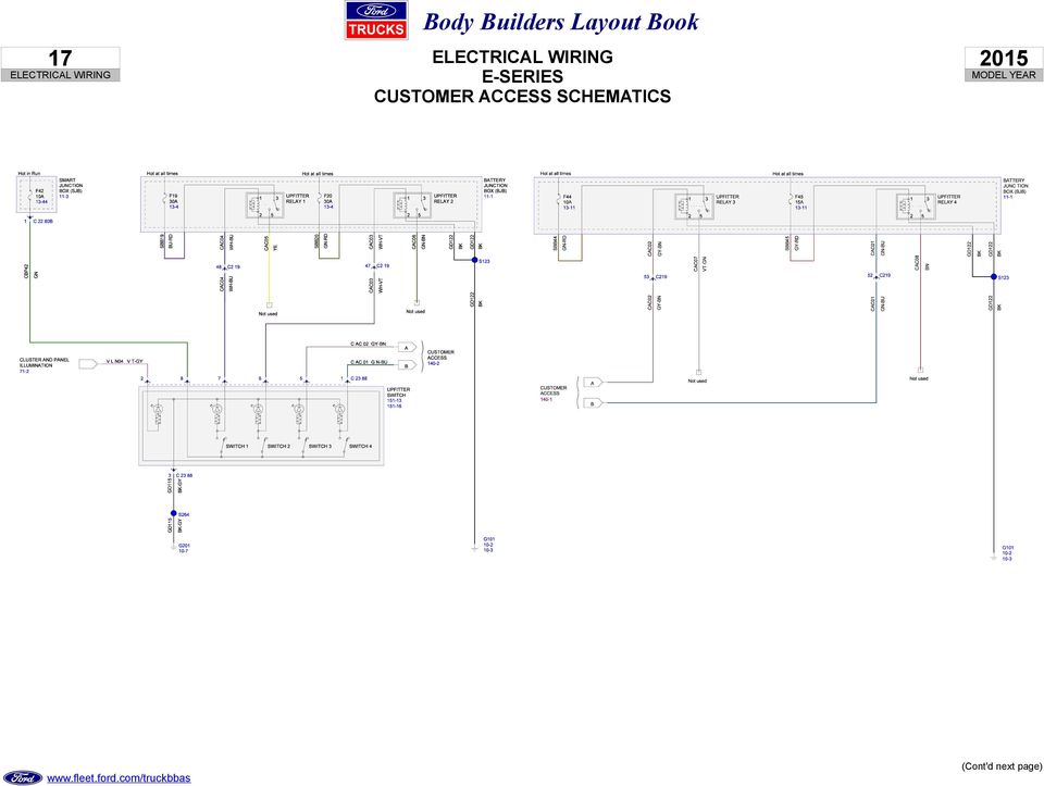
17 ESERIES CUSTOMER ACCESS SCHEMATICS 0
18 8 ESERIES CUSTOMER ACCESS SCHEMATICS (Cont'd) 0

19 9 ESERIES CUSTOMER ACCESS SCHEMATICS (Cont'd) 0

20 0 ESERIES CUSTOMER ACCESS SCHEMATICS (Cont'd) 0

21 ESERIES CUSTOMER ACCESS SCHEMATICS (Cont'd) 0
22 ESERIES CUSTOMER ACCESS SCHEMATICS (Cont'd) 0
23 ESERIES CUSTOMER ACCESS SCHEMATICS (Cont'd) 0
24 SUPER DUTY FSERIES CUSTOMER ACCESS SCHEMATICS 0
25 SUPER DUTY FSERIES CUSTOMER ACCESS SCHEMATICS (Cont'd) 0
26 SUPER DUTY FSERIES CUSTOMER ACCESS SCHEMATICS (Cont'd) 0
27 SUPER DUTY FSERIES CUSTOMER ACCESS SCHEMATICS (Cont'd) 0
28 8 SUPER DUTY FSERIES CUSTOMER ACCESS SCHEMATICS (Cont'd) 0
29 9 SUPER DUTY FSERIES CUSTOMER ACCESS SCHEMATICS (Cont'd) 0
Body Builders Layout Book
 INDEX 0 Page Customer Access Circuits General Information General Practices Addition of Lights or Electrical Devices ESeries Chassis Circuits Upfitter Switches Customer Access Circuits 80 Stripped Chassis
1978-83 Malibu 1978-87 Monte Carlo 1978-87 El Camino
 Important facts about this kit. 1. The dash panel used in this picture is used by permission of Covan's Classic. 2. This kit requires some modification to your original under dash wiring harness. It is
i ChatterBox! Motorcycle Security
 i Before you Start the Installation * Please read this manual to become familiar with the requirements necessary to complete the installation. * Use a high quality multi-meter to test all wires before
WIRING HARNESS FOR AS635P4. BLUE PLUG RED, BLUE, BLACK, WHITE - Plug in dual stage sensor harness
 WIRING HARNESS FOR AS635P4 ANTENNA NOT USED 5 PIN WHITE PLUG 2 PIN WHITE PLUG GREEN - PARKING BRAKE INPUT (-) BLUE - NOT USED 3 PIN BLUE PLUG RED, BLUE, BLACK, WHITE - Plug in dual stage sensor harness
SVE BULLETIN. 2005-2007 F-Series Super Duty Upfitter Switches
 005 00 FSeries Super Duty Switches See QR for Model Year 008 or Later at Link Below https://www.fleet.ford.com/truckbbas/nonhtml/qr.pdf Models Affected All 005 Model Year F50/350/450/550. Purpose To utilize
INSTALLATION INSTRUCTIONS
 Rear Vision System Tailgate Handle Camera Mirror Display 2004-2014 Ford F-150 and 2008-2015 Ford Super Duty (Kit part numbers 9002-9521) Kit Contents: Mirror Tailgate Handle with camera and harness Interior
INSTALLATION MANUAL 3RP / 5RP 4-BUTTON SERIES VEHICLE SECURITY SYSTEMS
 3RP / 5RP 4-BUTTON SERIES VEHICLE SECURITY SYSTEMS INSTALLATION MANUAL Before you begin the installation Read the INSTRUCTIONS! Always use a multi-meter when verifying vehicle wiring. Before mounting the
2007 W-SERIES (CHEVROLET & GMC) N-SERIES (ISUZU) 250 NPR/W3500, NPR HD/W4500, NQR/W5500, NRR/W5500-HD Diesel Electrical Symbols
 N-SERIES (ISUZU) 250 NPR/W3500, NPR HD/W4500, NQR/W5500, NRR/W5500-HD Diesel Electrical Symbols") 2007 W-SERIES (CHEVROLET & GMC) N-SERIES (ISUZU) 250 NPR/W3500, NPR HD/W4500, NQR/W5500, NRR/W5500-HD Diesel Electrical Symbols Symbol Meaning Symbol Meaning Symbol Meaning Fuse Electronic Parts Coil (Inductor),
2007 W-SERIES (CHEVROLET & GMC) N-SERIES (ISUZU) 250 NPR/W3500, NPR HD/W4500, NQR/W5500, NRR/W5500-HD Diesel Electrical Symbols Symbol Meaning Symbol Meaning Symbol Meaning Fuse Electronic Parts Coil (Inductor),
KEYLESS ENTRY UPGRADE SECURITY SYSTEM for 2004 TOYOTA HIGHLANDER
 KEYLESS ENTRY UPGRADE SECURITY SYSTEM for 2004 TOYOTA HIGHLANDER DEALER SERVICE AND INSTALLATION MANUAL KIT NO. 00016-30915 Contents PARTS LIST... 2 PARTS ILLUSTRATIONS... 2 VEHICLE PREPARATION... 3 INSTALLING
Multi Function, User Configurable Remote Vehicle Security System with 4 Button Replaceable Membrane Remote Transmitter
 MODEL PRO-9744 INSTALLATION MANUAL Multi Function, User Configurable Remote Vehicle Security System with 4 Button Replaceable Membrane Remote Transmitter This System Allows The Transmitter Buttons To Be
GENUINE PARTS INSTALLATION INSTRUCTIONS
 GENUINE PARTS INSTALLATION INSTRUCTIONS DESCRIPTION: Illuminated Kick Plate APPLICATION: Rogue (2011) PART NUMBER: 999G6 GX010 KIT CONTENTS: Item A B C G H QTY 1 1 1 D 1 E 1 F 3 15 6 Description Kick Plate,
1970-72 Chevelle. 1970-72 Chevelle. (500645) Gauge Cluster Kit Installation Instructions. (500645) Gauge Cluster Kit Installation Instructions
 Gauge Cluster Kit Installation Instructions. (500645) Gauge Cluster Kit Installation Instructions") 1970-72 Chevelle (500645) Gauge Cluster Kit Installation Instructions 1970-72 Chevelle (500645) Gauge Cluster Kit Installation Instructions STEP 1: There are 4 small gauges. This is a photo of the bare
1970-72 Chevelle (500645) Gauge Cluster Kit Installation Instructions 1970-72 Chevelle (500645) Gauge Cluster Kit Installation Instructions STEP 1: There are 4 small gauges. This is a photo of the bare
1R / 4-BUTTON SERIES
 Button 1 1R / 4-BUTTON SERIES VEHICLE SECURITY SYSTEM Standard Features: Two 4-Button Remote Transmitters Status indicator (LED) Valet / override switch Multi-tone siren Dual stage impact detector Remote
Power Door Locks Cruise Control System. Cigarette Lighter. Blower. Fan. Windshield Wiper System. See Note. High Wiper. Med. Low.
 + + Power Door Locks Cruise Control System Cigarette Lighter Power Windows Blower Fan Windshield Wiper System Clock Radio Rev. Light Switch See Note HVAC Side Marker Light Park/Turn Signal Low/High Beam
VEHICLE THEFT/SECURITY SYSTEMS
 DN VEHICLE THEFT/SECURITY SYSTEMS 8Q - 1 VEHICLE THEFT/SECURITY SYSTEMS TABLE OF CONTENTS page GENERAL INFORMATION INTRODUCTION...1 VEHICLE THEFT SECURITY SYSTEM....1 ENABLING...1 ARMING...1 DISARMING...2
ILISC515-A Shift Interlock (Manual Lift Door) 2015 Ford Transit, 3.7L and 3.5L
 2015 Ford Transit, 3.7L and 3.5L") An ISO 9001:2008 Registered Company ILISC515-A Shift Interlock (Manual Lift Door) 2015 Ford Transit, 3.7L and 3.5L Introduction The ILISC515-A is a microprocessor driven system for controlling wheelchair
An ISO 9001:2008 Registered Company ILISC515-A Shift Interlock (Manual Lift Door) 2015 Ford Transit, 3.7L and 3.5L Introduction The ILISC515-A is a microprocessor driven system for controlling wheelchair
ELECTRICAL WIRING (R.H. DRIVE VEHICLES)
") C-1 ELECTRICAL WIRING (R.H. DRIVE VEHICLES) CONTENTS GENERAL.......................... 3 WIRING HARNESS CONFIGURATION DIAGRAMS......................... 4 ENGINE COMPARTMENT................ 4 DASH PANEL...........................
C-1 ELECTRICAL WIRING (R.H. DRIVE VEHICLES) CONTENTS GENERAL.......................... 3 WIRING HARNESS CONFIGURATION DIAGRAMS......................... 4 ENGINE COMPARTMENT................ 4 DASH PANEL...........................
WIRE, TERMINAL AND CONNECTOR REPAIR CONDUCTORS
 CONDUCTORS Conductors are needed to complete the path for electrical current to flow from the power source to the working devices and back to the power source. Special wiring is needed for battery cables
Security and Remote Start Installation Guide for models: CA 6150 CA 6550
 PROFESSIONAL SERIES Security and Remote Start Installation Guide for models: CA 6150 CA 6550 2009 Audiovox Electronics Corporation. All rights reserved. 1 Table of Contents Before You Begin... 4 Wire Connection
PRO PLM Installation Instructions
 PRO PLM Installation Instructions PROFESSIONAL INSTALLATION STRONGLY RECOMMENDED Installation Precautions: Roll down window to avoid locking keys in vehicle during installation Avoid mounting components
SECTION 412-00 Climate Control System General Information and Diagnostics
 412-00-i Climate Control System General Information and Diagnostics 412-00-i SECTION 412-00 Climate Control System General Information and Diagnostics CONTENTS PAGE DIAGNOSIS AND TESTING Climate Control
VS Commodore LPG installation utilising an LPG Memcal and Apexus Quick-kit.
 VS Commodore LPG installation utilising an LPG Memcal and Apexus Quick-kit. Description of the components and operation LPG/Petrol changeover switch The LPG change-over switch is mounted in the instrument
PARTS & INSTALLATION INSTRUCTIONS MEYER SNOW PLOW LIGHTS
 Form 1-696 R1 January, 2003 PARTS & INSTALLATION INSTRUCTIONS MEYER SNOW PLOW LIGHTS PARTS LIST ITEM PART NO. QTY. DESCRIPTION 07033 1 SNOW PLOW LIGHT CARTON 1 07034 1 Snow Plow Light, Pass. Side (No Hardware)
2003/2004/2005 TOYOTA COROLLA
 2003/2004/2005 TOYOTA COROLLA KEYLESS ENTRY UPGRADE SECURITY SYSTEM INSTALLATION INSTRUCTIONS KIT NO. 00016-30120 SPECIAL NOTE: Installation Sequences After TMS and Safety mandated preparatory steps have
Part Number: 250-1859
 General Applicability 2010 Honda Insight 07- Kia Optima / Forte / Rondo/ 10- Sedona / 12 Soul 10- Hyundai Tucson / Elantra Touring ETC 2012 Accent / Elantra/ Genesis Recommended Tools Safety Tools Gloves,
by Myles H. Kitchen M.H. KITCHEN & ASSOCIATES www.auto-electronic.com (2002 X5 4.4 owner) March 2, 2004
 March 2, 2004") INSTALLING THE TEKONSHA PRODIGY ELECTRIC TRAILER BRAKE CONTROL IN THE BMW X5 by Myles H. Kitchen M.H. KITCHEN & ASSOCIATES www.auto-electronic.com (2002 X5 4.4 owner) March 2, 2004 INTRODUCTION The 2000
INSTALLING THE TEKONSHA PRODIGY ELECTRIC TRAILER BRAKE CONTROL IN THE BMW X5 by Myles H. Kitchen M.H. KITCHEN & ASSOCIATES www.auto-electronic.com (2002 X5 4.4 owner) March 2, 2004 INTRODUCTION The 2000
e-ask electronic Access Security Keyless-entry
 e-ask electronic Access Security Keyless-entry e-fob Keyless-entry entry System Full-Function Function Installation Manual FCC ID: TV2EFOB1 (UM20 ~ 22793-02) Table of Contents Introduction... 1 e-fob Operation
R02GA. July 31, 2002. Dear Blue Bird Owner:
 R02GA July 31, 2002 Dear Blue Bird Owner: This notice is sent to you in accordance with the requirements of the National Traffic and Motor Vehicle Safety Act. Blue Bird Body Company has determined that
Subaru Reference. This reference contains the following information: connector pinouts. connector pinouts
 Subject: Source: 1993 2010 Impreza, WRX, and Sti and 2002 07 Outback Sport ABS wiring diagrams, harness routing, and connector locations and pinouts Subaru service manuals This reference contains the following
INSTRUMENT PANEL. 1995 Volvo 850 DESCRIPTION & OPERATION. 1995-96 ACCESSORIES & EQUIPMENT Volvo Instrument Panels
 INSTRUMENT PANEL 1995 Volvo 850 1995-96 ACCESSORIES & EQUIPMENT Volvo Instrument Panels 850 WARNING: When working around steering column and before performing repairs, disconnect and shield battery ground
Mobile Data Power Model: MDP-25
 Mobile Data Power Model: MDP-25 Topic Section Features... 2 Operational Features Summary... 2 Back-up Battery Power Internal Charger Voltage Spike Protection RF Noise Filtering Warning of Imminent Loss
VEHICLE THEFT/SECURITY SYSTEM
 PL VEHICLE THEFT/SECURITY SYSTEM 8Q - 1 VEHICLE THEFT/SECURITY SYSTEM TABLE OF CONTENTS page DESCRIPTION AND OPERATION INTRODUCTION...1 VEHICLE THEFT/SECURITY SYSTEM (VTSS)... 1 (SKIS)... 2 SENTRY KEY
A&A CORVETTE PERFORMANCE C6 BOOST & FUEL GAUGE INSTALLATION INSTRUCTIONS
 A&A CORVETTE PERFORMANCE C6 BOOST & FUEL GAUGE INSTALLATION INSTRUCTIONS 1. Check your gauges before you take them out of the packaging to make sure they are at 0 (zero) psi for both boost and fuel pressure.
INSTALLATION GUIDE OWNER S GUIDE
 INSTALLATION GUIDE OWNER S GUIDE KEYLESS ENTRY MODELS KE100 / KE150 / 1702 CONTENTS System Features... 1 System Components... 1 Technical Assistance... 1 Before You Begin... 1 Precautions... 1-2 Making
INSTALLATION MANUAL VEHICLE SECURITY SYSTEM CE-SS200
 INSTALLATION MANUAL VEHICLE SECURITY SYSTEM CE-SS200 FUSION CULTURE TABLE OF CONTENTS There s no point doing something if no one notices. We ve always believed the way to make things happen is by getting
INSTRUCTIONS FOR THE INSTALLATION AND OPERATION OF ACTIVATOR II
 INSTRUCTIONS FOR THE INSTALLATION AND OPERATION OF ACTIVATOR II ELECTRONIC TRAILER BRAKE CONTROL 5500 FOR 2, 4, 6 & 8 BRAKE SYSTEMS IMPORTANT: READ AND FOLLOW THESE INSTRUCTIONS CAREFULLY. KEEP THESE INSTRUCTIONS
The Child Reminder System Installation Manual
 The Child Reminder System Installation Manual Revised June, 2006 Detailed installation information can be found at www.childreminder.com. Get through your installation quickly and easily by calling 1-888-330-6786
AEROMOTIVE Part # 16302 INSTALLATION INSTRUCTIONS
 AEROMOTIVE Part # 16302 INSTALLATION INSTRUCTIONS CAUTION: Installation of this product requires detailed knowledge of automotive systems and repair procedures. We recommend that this installation be carried
This file is available for free download at http://www.iluvmyrx7.com
 This file is available for free download at http://www.iluvmyrx7.com This file is fully text-searchable select Edit and Find and type in what you re looking for. This file is intended more for online viewing
Schematic - 379 Model Family Electrical P94-6023 C 01
 Schematic - 379 Model Family Electrical P94-6023 C 01 SH NO. TITLE 1) INDEX 2) ARCHITECTURE 85) ENGINE - CUM ISX ( BJ SERVICES ) ( CONTINUED ) 3) LOCATION OF MAJOR COMPONENTS 86) ENGINE ECU POWER 4) LOCATION
Before installation it is important to know what parts you have and what the capabilities of these parts are.
 INSTALLATION GUIDE Before installation it is important to know what parts you have and what the capabilities of these parts are. The Recon XZT is the smallest and most powerful gauge of its kind. With
INSTALLATION GUIDE OWNER S GUIDE
 INSTALLATION GUIDE OWNER S GUIDE SECURITY SYSTEM PRO-SERIES 5002 CONTENTS System Features... 1-2 System Components... 2 Technical Assistance... 2 Before You Begin... 2 Precautions... 2-3 Making Connections...
INTRODUCTION CONTENTS
 1 INTRODUCTION This booklet contains Wiring Diagrams for 1979 vehicles listed in the contents below. All diagrams contained in this booklet are based on the latest product information available at the
ELECTRONICS G H I J K L M
 ELECTRONICS TM LASER INSTALLATION INSTRUCTIONS PARTS KIT Parts Kit includes the following: A- (1) Universal Mounting Bracket A B- (1) Red L.E.D. Laser Alert Light C- (1) Piezo Beeper w/ O Ring Tape D-
SAF-T-LINER MVP-EF PARTS MANUAL. Electrical Section. Page 7-1. Electrical 10/96
 Electrical Page 7-1 Switch Cabinet Page 7-2 Electrical Switch Cabinet Item Part Num. Number Qty. Description Notes 1 52002053 1 Cabinet - Switch, Assembly For Thomas Forward Control 2 68000868 1 Insulator
Electrical Systems - IQAN Digital Control System. IQAN Control System Components... 5.1.3
 Section 5.1 Electrical Systems - IQAN Digital Control System IQAN Control System Components........................... 5.1.3 IQAN Operational Description: At Machine Startup.....................................
Mazda CX7 2007-09 99-7508
 INSTALLATION INSTRUCTIONS FOR PART 99-7508 APPLICATIONS Mazda CX7 2007-09 99-7508 KIT FEATURES DIN Radio Provision with Pocket ISO Mount Radio Provision with Pocket Double DIN Mount Radio Provision Stacked
REMOVAL AND INSTALLATION
 303-01C-1 REMOVAL AND INSTALLATION Engine Body On Special Tool(s) Adapter For 303-D043 303-D043-02 or equivalent Special Tool(s) 303-01C-1 Turbocharger Lifting Bracket 303-1266 Wrench, Fan Clutch Nut 303-214
Installation Instructions
 Installation Instructions for EVS II Security and Keyless Entry Systems Note: It is recommended that this installation take place prior to rustproofing. The individual delivering the vehicle should review
Back-Up Camera Installation Guide
 Hz Hz In This Guide: Back-up camera installation requires connecting power wiring to the existing reverse lighting circuit and adding a chassis ground, as well as routing a video signal cable to the front
Advantium 2 Plus Alarm
 ADI 9510-B Advantium 2 Plus Alarm INSTALLATION AND OPERATING INSTRUCTIONS Carefully Read These Instructions Before Operating Carefully Read These Controls Corporation of America 1501 Harpers Road Virginia
INSTALLATION INSTRUCTIONS
 INSTALLATION INSTRUCTIONS Application Outboards Faria 5 Gauge Set* Publication No. Description Part Number Honda Code PII53606A White faced, flat lens 06300-ZW5-010ZB 6315410 Issue Date Black faced, flat
HONDA ACCORD 1985-2005
 HONDA ACCORD 1985-2005 VEHICLE WIRING Copyright 2002-2004 Triple S Customs WIRING INFORMATION: 1985 Honda Accord WIRE WIRE COLOR WIRE LOCATION 12V CONSTANT WHITE or WHITE/BLACK Ignition Harness STARTER
VOYAGER 570G. 744A Sprayer Control
 VOYAGER 570G 744A Sprayer Control U S E R M A N U A L U S E R M A N U A L Table of Contents CHAPTER 1 - INTRODUCTION...1 SYSTEM CONFIGURATIONS...1 KIT CONTENTS...3 CONTROL HOUSING ASSEMBLY...5 CHAPTER
INSTALLATION INSTRUCTIONS
 Rear Vision System Aftermarket and Factory 5.0, 8.4 and 6.1 MyGig Touch Screen Display (Factory Display requires Chrysler/Dodge dealer to activate) 2009 Current* Dodge Ram (Kit part number 1009-6503) *NOTE:
HOW TO READ THE WIRING DIAGRAMS
 A-1 HOW TO READ THE WIRING DIAGRAMS CONTENTS COMPOSITION AND CONTENTS OF WIRING DIAGRAMS... 2 HOW TO READ CONFIGURATION DIAGRAMS... 3 MARKING FOR CONNECTOR EARTHING... 6 WIRE COLOUR CODES... 9 ABBREVIATION
PT-6000 Power Tower INSTALLATION MANUAL SPECIFICATIONS
 PT-6000 Power Tower INSTALLATION MANUAL 10.5 9.75 12 22.75 10.75 MAXIMUM SOIL HEIGHT: DO NOT ALLOW FILL TO EXCEED THIS LEVEL! 11.5 4 4 13 Optional PT-BASE for new installations or when previous 2000/6000
VEHICLE SPEED CONTROL SYSTEM
 PL VEHICLE SPEED CONTROL SYSTEM 8H - 1 VEHICLE SPEED CONTROL SYSTEM TABLE OF CONTENTS page DESCRIPTION AND SPEED CONTROL SYSTEM...1 SPEED CONTROL SERVO-PCM OUTPUT....2 SPEED CONTROL SWITCHES PCM INPUT...2
Remote Access System Installation
 2011-2013 Explorer Remote Access Remote Access System Installation CONTENTS VEHICLE PREPARATION Hood Switch Wire Harness Installation Hood Switch Installation RMST Module Installation RMU Module Installation
INSTALLATION GUIDE. www.security.soundstream.com FCC ID NOTICE
 AL.1 AUTO SECURITY SYSTEM INSTALLATION GUIDE www.security.soundstream.com FCC ID NOTICE This device complies with Part 15 of the FCC rules. Operation is subject to the following conditions: 1. This device
On/Off Relay Switch and 3-Way Switch Kit
 45637/45638 Wireless Lighting Control On/Off Relay Switch and 3-Way Switch Kit marthome Control the On/Off status of permanently installed lighting, fans and more! www.lowes.com/iris 2012 JASCO Made in
PUSH BUTTON START INSTALLATION MANUAL
 PUSH BUTTON START INSTALLATION MANUAL ALTHOUGH THIS PRODUCT HAS BEEN THOROUGHLY TESTED KPIERSON TECHNOLOGIES ASSUMES NO RESPONSIBILITY FOR ANY DAMAGE THAT MAY RESULT BY THE INSTALLATION OF THIS PRODUCT.
6-years/75,000 miles Comprehensive coverage Subsequent Owner Warranty $100 Deductible
 LINCOLN PREMIER LIMITED WARRANTY 6-years/75,000 miles Comprehensive coverage Subsequent Owner Warranty $100 Deductible Comprehensive Coverage Because Lincoln has always been a brand you can trust and respect,
ANTI-THEFT SYSTEM. 1995 Volvo 850 DESCRIPTION & OPERATION BASIC ALARM. 1995-96 ACCESSORIES & EQUIPMENT Volvo Anti-Theft Systems
 ANTI-THEFT SYSTEM 1995 Volvo 850 1995-96 ACCESSORIES & EQUIPMENT Volvo Anti-Theft Systems 850 DESCRIPTION & OPERATION WARNING: Deactivate air bag system before performing any service operation. For 1995
CMD-8000 rev. A COMMANDER SERIES REMOTE CONTROL ENTRY SYSTEM
 INTRODUCTION CMD-8000 rev. A COMMANDER SERIES REMOTE CONTROL ENTRY SYSTEM Thank you for purchasing the CMD-8000 Commander from Dakota Digital. This, along with many other products that Dakota Digital has
Recommended Practice for Installation of Transit Vehicle Fire Protection Systems
 Recommended Practice for Installation of Transit Vehicle Fire Protection Systems Approved October 25, 2007 APTA Fire Safety Working Group Approved May 3, 2008 APTA Bus Safety Committee Approved October
EXTENDED-WIRE HANDLEBAR SWITCH KITS
 -J03396 REV. 2010-02-11 EXTENDED-WIRE HANDLEBAR SWITCH KITS ENERAL Kit Numbers 70246-10, 70318-10 Models Neither of these kits is compatible with cruise control-equipped 2007 or earlier models. Kit 70246-10
Left Hand Limit Switch. Housing. Left Hand. Connections. Motor Connector BROWN PURPLE GRAY BLACK DARK BLUE BLACK BROWN BROWN LIGHT BLUE.
 LIGHT BLUE GRAY PURPLE Circuit Breaker Intput Circuit Breaker Output #1 Relay Left Hand Limit Switch Housing Left Hand Motor Connector Right Hand Limit Switch on Radiator Support Right Hand Limit Switch
Installation Instructions: Electrical System for Towing Hitch... 3
 ... 3 Installation Instructions: Electrical System for Towing Hitch... 3 321 527 391 103-002 - 51/12 VW Polo A05 RHD Westfalia 321 525 300 143 VW Polo V RHD, 06/09-321 527 300 143 VW Polo V RHD, 06/09-4
************* OWNER'S MANUAL BAMF800/2 BAMF1250/2 BAMF1800/2 BAMF2200/2 BAMF2600/2 BAMF1200/4 BAMF1600/4 BAMF2000/1D BAMF4000/1D BAMF5500/1D
 ************* OWNER'S MANUAL BAMF800/2 BAMF1250/2 BAMF1800/2 BAMF2200/2 BAMF2600/2 BAMF1200/4 BAMF1600/4 BAMF2000/1D BAMF4000/1D BAMF5500/1D INTRODUCTION Power Acoustik amplifiers provide high-performance
RECOMMENDED TOOLS PERSONAL & VEHICLE PROTECTION SAFETY GLASSES
 PART NUMBER: 250-9612 GENERAL APPLICABILITY THIS CRUISE WAS TESTED AND VERIFIED ON: FORD FOCUS SE & S MODELS (AT/MT) FORD TRANSIT ALL MODELS RECOMMENDED TOOLS PERSONAL & VEHICLE PROTECTION SAFETY GLASSES
MOTOR VEHICLE MECHANIC REPAIR CATEGORIES
 Chapter 8: Motor Vehicle Mechanic Repair Categories Page 1 CHAPTER 8 MOTOR VEHICLE MECHANIC REPAIR CATEGORIES Section 8-1 REQUIREMENT Section 10 of the Motor Vehicle Service and Repair Act (MCL 257.1310)
For a simple splice connection look at figure 21. This basic type of splice can be used almost exclusively when hooking up your wiring.
 Page 1 of 10 IMPORTANT: Before starting installation, please be sure that all items which were supplied with the kit are accounted for. Note: These instructions are to be used in conjunction with the instructions
Electronic Power Control
 Service. Self-Study Programme 210 Electronic Power Control Design and Function With the Electronic Power Control system, the throttle valve is actuated only by an electric motor. This eliminates the need
INSTALLATION INSTRUCTIONS: Viewline 52 mm
 -5 Safety information The product was developed, manufactured and inspected according to the basic safety requirements of EC Guidelines and state-of-the-art technology. The instrument is designed for use
Question: How Do I Install a Back of Cab Remote Power Module Kit and Switch Pack?
 Question: How Do I Install a Back of Cab Remote Power Module Kit and Switch Pack? nswer: Purchase a remote and switch pack kit, Part Number 008C9 from International Service Parts. Place all parts on a
Networkfleet 3500 Product Line Installation Guide
 Networkfleet 3500 Product Line Installation Guide Light/Medium Duty (L3500) Heavy Duty (H3500) Universal (U3500) www.networkcar.com/fleet Customer Care: (866) 227-7323 customercare@networkcar.com Table
Installation Instructions
 H5HK Series Installation Instructions 3 Phase Electric Heater Kits 7.5 and 0 TON Package A/C Systems Description Installation of 08/40V and 480V H5HK 3 Phase Heater Kits in 7.5 and 0 TON Packaged Air Conditioners.
Manual for Fire Suppression & Methane Detection System
 Manual for Fire Suppression & Methane Detection System Fogmaker North America Post address: 150 Gordon Dr Exton, PA 19341 Delivery address: 150 Gordon Dr Exton, PA 19341 Tel: 610-265-3610 Fax: 610-265-8327
SECURITY SYSTEM ADP-CAN
 INSTALLATION INSTRUCTION SECURITY SYSTEM ADP-CAN Introduction Motorcar security system ADP-CAN is for motorcars provided with CAN net. It is for the work with the motorcar factory security systems or remote
2. Remove rear cover of head lamp if bulbs are covered/sealed within the housings, and remove halogen bulb carefully.
 These instructions are designed to address most general installation procedures across vehicles and should not be considered vehicle make, model or year specific. Please contact the vendor directly for
SKYPATROL TT8750. Installer GUIDE. SKYPATROL highly recommends that a certified professional technician install the unit into your asset.
 SKYPATROL TT8750 Installer GUIDE SKYPATROL highly recommends that a certified professional technician install the unit into your asset. BE SURE TO REGISTER YOUR DEVICE ON LINE PRIOR TO HAVING IT INSTALLED
SP-100 REMOTE CONTROL ALARM SYSTEM INSTALLATION & OPERATING INSTRUCTIONS INTRODUCTION
 SP-100 REMOTE CONTROL ALARM SYSTEM INSTALLATION & OPERATING INSTRUCTIONS INTRODUCTION CONGRATULATIONS on your choice of a Security Plus Remote Alarm System by Crimestopper Security Products Inc. This booklet
K9 Heat Alarm Owners Manual HA-1520
 K9 Heat Alarm Owners Manual HA-1520 Your K9 Heat Alarm is a state of the art product designed and developed by ACEK9.COM a division of Radiotronics, Inc. It is a unique blend of positive features taken
PATENTED: www.voxxintl.com/company/patents
 Model PRO9776C Installation Manual Vehicle Security System Table Of Contents: with Remote Start Before You Begin Page 2 Wire Harnesses Quick View Page 3-4 Installation of the Major Components Page 5 Wiring
TOYOTA TACOMA 2008- HANDS FREE BLU LOGIC Preparation
 TOYOTA TACOMA 2008- HANDS FREE BLU LOGIC Preparation Part #: PT923-00112 Conflicts: JBL Audio, Factory Navigation NOTE: Part number of this accessory may not be the same as the part number shown. Kit Contents:
P150SC15. Designed for 2015 Ford F150 Super-Cab and Super-Crew vehicles without Sony System. 2015 Stillwater Designs P150SC15-A2-20150813
 P150SC15 Designed for 2015 Ford F150 Super-Cab and Super-Crew vehicles without Sony System Subwoofer Assembly Amplifier Assembly Amplifier Harness 2015 Stillwater Designs P150SC15-A2-20150813 M6 Bolt M6
2013 VTech Printed in China 91-009656-000 US
 Rechargeable Power Pack User s Manual 2013 VTech Printed in China 91-009656-000 US INTRODUCTION The Rechargeable Power Pack makes it easier than ever to keep the InnoTab 3 or InnoTab 3S charged and ready
Transporter Fitting Locations No. 804 / 1
 Page 1 of 10 Transporter Fitting Locations No. 804 / 1 Pin connector assigment of selected connections Overview: 1 - Ignition/starter switch -D- On steering column Connector assigment chapter 2 - Onboard
Installation Instructions. ThermoCall TC4. Entry/Advanced
 Installation Instructions ThermoCall TC4 Entry/Advanced Thermo Call TC4 1 2 # 24990A 965 082 AMP 3 4 # 98393A # 67769A Thermo Call TC4 5 ThermoCall TC4 Entry 1 2 3 4 5 6 7 8 9 10 11 12 sw Please refer
Wiring diagrams 14 1. Component key for wiring diagrams 1 to 29 Note: Not all the items listed will be fitted to all models
 Wiring diagrams 14 1 Component key for wiring diagrams 1 to 29 Note: Not all the items listed will be fitted to all models No Description 00200 Alternator with built-in regulator 00500 Battery 01001 Starter
- power windows - alarm system - electric door mirror control - door warning light - central locking - seat memory
 Door Wiring Harness Plug Connections Binder -, Electrics Vehicle Type: (86) Model Year: 7 (V) Concern: Door wiring harness plug connections X11 / X12. Information: The rubber boot for the door connector
535T Window Automation System
 535T Window Automation System Installation Guide NOTE: This product is intended for installation by a professional installer only! Any attempt to install this product by any person other than a trained
BL-DBK150A DUAL BATTERY 12v 150 AMP SMART SYSTEM
 BL-DBK150A DUAL BATTERY 12v 150 AMP SMART SYSTEM Waterproof and Shockproof Easy DIY Dual Battery System BL-DBK150A Supplied Parts List Parts List 1 x 12v 150Amp Electronic Dual Battery Smart Controller
PATENTED: www.voxxintl.com/company/patents
 Model APS-997C Installation Manual 2 Way LCD Vehicle Security and Table Of Contents: Remote Start System Before You Begin Page 2 Wire Harnesses Quick View Page 3 and 4 Installation Of The Major Components
Copyright 2002-2004 Triple S Customs
 CHEVROLET SILVERADO 1988-2005 VEHICLE WIRING Copyright 2002-2004 Triple S Customs WIRING INFORMATION: 1988 Chevy Silverado Full-Size 2- POWER DOOR LOCK (5-wire reverse polarity) POWER DOOR UNLOCK (5-wire
OVEN PARTS For Models:GMC305PDB07, GMC305PDQ07, GMC305PDT07, GMC305PDS07 (Black) (White) (Biscuit) (S.Steel)
 (White) (Biscuit) (S.Steel)") OVEN PARTS 30" BUILT IN ELECTRIC COMBO SENSOR/SC (GOLD LINE) 7 03 Litho In U.S.A. (cre) 1 Part No. OVEN PARTS NOTE: The screws and nuts required to attach a part are listed immediately following that part.
OVEN PARTS 30" BUILT IN ELECTRIC COMBO SENSOR/SC (GOLD LINE) 7 03 Litho In U.S.A. (cre) 1 Part No. OVEN PARTS NOTE: The screws and nuts required to attach a part are listed immediately following that part.
TOYOTA Tundra 2007 - BACK-UP CAMERA SYSTEM Preparation
 Preparation Part Number(s): PT233-34070, PT923-35070-11, PT923-35070-43 NOTE: Part number of this accessory may not be the same as part number shown. Back Up Monitor Kit Contents PT923-35070-11 / PT923-35070-43
specializing in AIR CONDITIONING, PARTS AND SYSTEMS for your classic vehicle PERFECT FIT IN-DASH HEAT/ COOL/ DEFROST 1967-72 CHEVROLET PICKUP
 specializing in AIR CONDITIONING, PARTS AND SYSTEMS for your classic vehicle PERFECT FIT IN-DASH HEAT/ COOL/ DEFROST 1967-72 CHEVROLET PICKUP CONTROL & OPERATING INSTRUCTIONS The controls on your new Perfect