Regulations for the Installation of Electrical Wiring, Electrical Equipment and Air Conditioning Equipment
|
|
|
- Marsha Stevens
- 8 years ago
- Views:
Transcription

1 Regulations for the Installation of Electrical Wiring, Electrical Equipment and Air Conditioning Equipment Qatar General Electricity & Water Corporation KAHRAMAA Customer Services Department State of Qatar Edition: December 2010


2 Contents Section Page Scope and Climatic Conditions 01 3 Definitions 02 5 Requirements for Safety Substations, Services Arrangements and Distribution Boards Earthing and Earth Leakage Protection Installations Details Final Sub Circuits Electric Motors, Circuits and Controllers Power Factor Correction Emergency, Standby Systems and Fire Alarm Installations Inspection and Testing Thermal Insulation of Building Heating Ventilation and Air Conditioning Tables Tables 74 Maximum Demand and Diversity Appendix No Standards Appendix No The Specifications of Electrical Service Cabinet Appendix No Building Envelope Compliance Forms Appendix No Air Conditioning Equipment Compliance Forms Appendix No Box : 41 Doha-Qatar,Tel. No. : ( ) ( ), Fax No. : ( ) ( ) Customers Services Deartment. 2

3 Section 01: Scope and Climatic Conditions Scope: 101 These regulations are applicable to electrical installations in buildings in general, including domestic premises, shops, offices, small and medium size industrial establishments, small and medium size public buildings. Large industrial and public buildings shall be subject of detailed study by the Customer Services Department (KAHRAMAA) and approval shall be obtained before commencement of construction. The single line diagram submitted must carry a note that The Electrical Installations Shall Be Carried Out In Compliance With The Current Edition Of The Regulations For Installation Of Electrical Wiring, Electrical Equipment And Air Conditioning Equipment. The authorized electrical contractor shall consider all terms, conditions and requirements as stated on the electrical building permit application form. 102 Compliance with these regulations is compulsory. Electrical power supply will not be made available if these regulations are not met with entirely. Any deviation to this regulation to be noticed to the Qatar General Electricity & Water Corporation KAHRAMAA by the contractor or consultant. 103 These regulations does not provide for all types of conditions encompass the type of installation generally encountered. Where difficult or special situations arise which are not covered or allowed for in these regulations, the services of the Qatar General Electricity & Water Corporation KAHRAMAA may be sought to obtain the best solution. 104 Exclusions from Scope : These regulations does not apply to : 1. Systems for the transmission and distribution of energy to the public or to power except as detailed in Section Those aspects of installations in potentially explosive atmosphere relating to methods of dealing with the explosion hazard which are specified in BS EN 50014: 1998 (Electrical Apparatus For Potentially Explosive Atmospheres. General Requirements), or in premises where the fire risks are of an usual character so as to require special measures. 3. Those parts of telecommunications (e.g. radio, telephone, bell, call and sound distribution and data transmission), fire alarm, intruder alarm, emergency lighting circuits and equipments that are fed from a safety course. Requirements for the segregation of other circuits from such circuits are however, included. Note 01 : For fire alarm systems, see BS 5839 Part 06 : 1995 (Code Of Practice For The Design And Installation Of Fire Detection And Alarm Systems In Dwellings) and for emergency lighting of premises, see BS 5266 Part 07 (Lighting Applications. Emergency Lighting), See Also BS EN Electric traction equipment. 5. Electrical equipment of motor vehicles, except those to which the requirements of these regulations concerning caravans are applicable.. Box : 41 Doha-Qatar,Tel. No. : ( ) ( ), Fax No. : ( ) ( ) Customers Services Deartment. 3

4 6. Electrical equipment on board ships. 7. Electrical equipment on offshore installations. 8. Electrical equipment of aircraft. 9. Installation in mines and quarries. 10. Radio interference suppression equipment, except so far as it affects the safety on an electrical installation. 11. Lightning protection of buildings. 12. Motor Control Centre (MCC). The manufacturer drawings of MCC shall not be evaluated or approved by Customers Services Department (KAHRAMAA), only the Medium Voltage side (MV - Panel) up to the vertical bus-bar shall be evaluated and approved by KAHRAMAA. 13. Street Lighting Feeder Pillar. The manufacturer drawings shall not be evaluated or approved by Customers Services Department (KAHRAMAA). Note 02 : For guidance on protection of building against lightning, see BS 6651 : 1999 ( Code Of Practice For Protection Of Structures Against Lightning ). Climatic Conditions in The State of Qatar : 105 Qatar experiences a tropical climate and generally the ground area is at sea level. The maximum ambient shade temperature recorded has been 50 0 C and the minimum 0 0 C. The atmosphere is salt laden and very corrosive. The prevailing winds are northerly and gales with gusts approaching 140 KPH have been recorded accompanied by a high level of dust in the air. The maximum ground temperature is 30 0 C at a depth of 1 metre. The maximum seawater temperature is 40 0 C with a maximum tidal variation of approximately 2.40 metres. The mean and maximum Relative Humidity during the summer month of April to September inclusive are as follows at the associated temperatures given : Mean % R.H 0 C % R.H. Maximum % R.H 0 C % R.H The average annual rainfall is 50 mm and generally falls between the months of January and April inclusive. The periods of high humidity are common and a relative humidity of 100 % at 30 0 C has been recorded.. Box : 41 Doha-Qatar,Tel. No. : ( ) ( ), Fax No. : ( ) ( ) Customers Services Deartment. 4
.")
5 Section 02: Definitions Accessory: Any device, other than a lighting fitting, associated with the wiring and current using appliances of an installation, e.g. a switch, a fuse, a plug, a socket outlet, a lamp holder or a ceiling rose. Adapter, Socket Outlet: An accessory for insertion into a socket outlet and containing metal contacts, to which may be fitted one or more plugs for the purpose of connecting to the supply, portable lighting fitting or current using appliances. Ambient Temperature (for Cable): The temperature of the surrounding medium under normal conditions, at a suitable in which cables are installed, or are to be installed, including the effect of any artificial heating used in the building by any local source of heat. Apparatus: Electrical apparatus, including all machines, equipment and fittings in which conductors are used or of which they form a part. Appliance : Any device which utilise electricity for a particular purpose, excluding a lighting or an independent motor. Bonded (As Applied to Items of Metal Work): Connected together electrically, not normally for the purpose of carrying current but so as to ensure a common potential Bunched: Cables are said to be bunched when two or more are contained within a single conduit or trunking or, if not separated from each other. Caravan: Any structure designed or adapted for human habitation which is capable of being moved from one to another ( whether by being towed or being transported on a motor vehicle or trailer ) and any other motor vehicle so designed or adapted. The regulations apply where supply is provided by mains electricity or by generator at a voltage exceeding 50 Volts between poles. Channel (for Cables): A groove cut or formed in part of a building and intended to receive on a more cables, the groove having removable or hinged covers to allow cables to be laid therein. Circuit Breaker: A mechanical device for making and breaking a circuit, both under normal conditions and under abnormal conditions, such as those of an overload or short circuit being broken automatically. Circuit Conductor: A current carrying conductor forming part a circuit or final sub circuit, but excluding the earth continuity conductor Conductor (of Core or Cable): The conducting portion, consisting of a single wire or of a group of wires in contact with each other. For earthed concentric wiring, the term may also denote the metal sheath of a cable. Connector: A device intended for connection to a flexible core of flexible cable, which has protected current carrying contact tubes similar to those of a socket outlet. Customer s Installation: Wiring and apparatus situated upon the customer s premises and controlled or installed by him, excluding any switchgear of the supply undertaking which the customer may be permitted to use.. Box : 41 Doha-Qatar,Tel. No. : ( ) ( ), Fax No. : ( ) ( ) Customers Services Deartment. 5
: The temperature of the surrounding medium under normal conditions, at a suitable in which cables are installed, or are to be installed, including the effect of any")
6 Customer s Terminals: The point in the customer s installation at which the incoming supply of energy is delivered to that installation. Core (of Cable): The conductor with its insulation but not including any outer covering for mechanical or other protection. Damp And Dust Proof : Applied to apparatus and accessories to denote that the live and other component parts are protected by an enclosure or enclosures being so protected and or fitted as to prevent the ready ingress of dust and or moisture. Damp Situation: A situation in which moisture is either permanently present or intermittently present, to such an extent as to be likely to impair the effectiveness of an installation conforming to the requirements for ordinary situations. Dead: At earth potential and disconnected from any live system. Distribution Board: An assemblage of parts, including one or more fuse or circuit breakers, arranged for the distribution of electrical energy. Duct (for Cables): A closed passage way formed underground in intended to receive one or more cables which may be drawn in. a structure and Earth Continuity Conductor: The conductor, including any clamp, connecting to the customer s earthing terminal or to the frame terminal of a voltage operated earth leakage circuit breaker or to each other, those parts of an installation which are required to be earthed. It may be the metal sheath and or armouring if a cable or the special earth continuity conductor of a cable or flexible cord incorporating such a conductor. Earth Electrode: A metal rod or rods, a system of underground metal pipes or other conducting object, providing an effective connection with the general mass of the earth. Earthed: Effectively connected to the general mass of the earth. Earthed Concentric Wiring: A sheath return wiring system in which one or more insulated conductors carrying the line current are completely surrounded throughout their length by a conductor which acts as the earth continuity conductor. Earthing Lead: The final conductor by which the connection to the earth electrode or other means of earthing is made Electric Discharge Lamp: An electric lamp comprising an hermetically sealed bulb or tube containing gas and or metal intended to be vaporised during operation and fitted with electrodes between which a discharge of electricity takes places, the useful light being emitted either by the discharge through the gas or vapour or by the fluorescence of a translucent coating which may be on the inner surface of the outer tube or bulb. Electrode Boiler (or Electrode Water Heater): Apparatus for the electrical heating of water by the passage of an electric current between electrodes immersed in the water. Excess Current Protection Close: Excess current protection which will operate within Four Hours at 1.50 times the designed load current of the circuit which is protects.. Box : 41 Doha-Qatar,Tel. No. : ( ) ( ), Fax No. : ( ) ( ) Customers Services Deartment. 6

7 Devices Affording Close Excess Current Protection Include: 1. BS 88 Part 05: 1988 (1992) (Specification Of Supplementary Requirements For Fuse - Links For Use In A.C. Electricity Supply Networks) fuses fitted with fuse links marked to indicate a class P, or class Q1 fusing factor. 2. Fuses fitted with fuse links complying with BS 1361: 1971 (1986) (Specification For Cartridge Fuses For A.C. Circuits In Domestic And Similar Premises). 3. Miniature Circuit Breaker (MCB) complying with BS EN : 1991 (Specification For Circuit - Breakers For Overcurrent Protection For Household And Similar Installations) and Moulded Case Circuit Breaker (MCCB) complying with BS EN Part 02 : 1996 (Circuit - Breakers). 4. Circuit breakers set to operate at an overload not exceeding 1.50 times the designed load current of the circuit. Excess Current Protection Coarse: Excess current protection which will not operate within Four Hours at 1.50 times the designed load current of the circuit which it protects. The device affording coarse excess current protection include BS 88 Part 05 : 1988 ( 1992 ) ( Specification Of Supplementary Requirements For Fuse - Links For Use In A.C. Electricity Supply Networks ) fuses fitted with fuse links marked to indicate a class Q2 or class R fusing factor. Final Sub Circuit: An outgoing circuit connected to a distribution board and intended to supply electrical energy to current using apparatus, either directly or through socket outlets or fused spur boxes. Flameproof: Applied to apparatus to denote that the containing case or other enclose withstand without injury any explosion of prescribed flammable gas that may occur within it under practical conditions of operation within the rating of the apparatus ( and recognised overloads, if any, associated therewith ) and will prevent the transmission of flame such as will ignite any prescribed flammable gas that may be present in the surrounding atmosphere. Flammable: A flammable material is one capable of being easily ignited. Flexible Cord: A flexible cable in which the cross sectional area of each conductor does not exceed 4 mm. Flood Lighting: Flood lights are broad - beamed, high intensity artificial lights, typical application is to illuminate outdoor playing fields while an outdoor sports event is being held during low - light conditions. Fuse: A device for opening a circuit by means of a fuse element designed to melt when an excessive current flows. It normally consists of a fuse base and fuse link. The fuse link may take the form of a cartridge or a carrier supporting a fuse element. For the purpose of these regulations the current rating of a fuse is a current, less than the minimum fuse current, stated by the maker as the current that the fuse and the fuse link with which it is fitted will carry continuously without deterioration, see BS 88 Part 05 : 1988 ( 1992 ) ( Specification Of Supplementary Requirements For Fuse - Links For Use In A.C. Electricity Supply Networks ).. Box : 41 Doha-Qatar,Tel. No. : ( ) ( ), Fax No. : ( ) ( ) Customers Services Deartment. 7
 complying with BS EN 60947 Part 02 : 1996 (Circuit - Breakers). 4. Circuit breakers set to operate at an overload not exceeding 1.50 times the designed load current of the circuit.")
8 Fuse Element: That part of a fuse which designed to melt and thus open a circuit. Insulation: Suitable non conducting material enclosing, surrounding or supporting a conductor. Intrinsically Safe: 1. Applied to a circuit, denotes that any electrical sparking that may occur, in normal working under the conditions specified by the certifying authority and with the prescribed components, is incapable of causing an ignition of the prescribed flammable gas or vapour. 2. Applied to apparatus, denotes that it is so constructed that when installed and operated under the conditions specified by the certifying authority, any electrical sparking that may occur in normal working, either in the apparatus or in the circuit associated therewith, is incapable of causing ignition of the prescribed flammable gas or vapour. Isolator: A mechanical device capable of opening or closing a circuit under conditions of no load or negligible current. Not To Be Used For The Main Disconnecting Device Of A Main Switchboard. The Isolator shall be complying with BS EN Part 03 : 1999 ( Switches, Disconnectors, Switch - Disconnectors And Fuse - Combination Units ). Live: In relation to a conductor, means that, under working conditions : 1. A difference of voltage exists between the conductor and earth or; 2. It is connected to the middle wire, common return wire or neutral wire of a supply system in which that wire is not permanently and solidly earthed. Neutral Conductor: The neutral conductor of a 3 Phase 4 Wire system, the conductor of a Single Phase of D.C. installation which is earthed by the supply undertaking ( Or Otherwise At The Source Of The Supply ) or the middle wire or common return conductor of a 3 Wire D.C. or 3 Wire Single Phase system. Non Combustible : A non - combustible material is one which is not capable of undergoing combustion and satisfies the performance requirements specified in the non - combustibility test of BS 476 (Fire Tests On Building Materials And Structures), BS 476 Part 04 : 1970 (1984 ) ( Non - Combustibility Test For Materials ). Non Conducting: Presenting a barrier against risk of electric shock when interposed in series with a source of low voltage. Oil Resisting and Flame Retardant Sheath (of Cable): Oil resisting and flame retardant sheath complying with BS 6899 : 1991 ( Specification For Rubber Insulation And Sheath Of Electric Cables ) ( e.g. based on poly chloroprene ). Plug: A device intended for connection to a flexible cord or flexible cable which can be engaged manually with a socket of connector or adapter and which has currently contact pins which may be exposed when not engaged.. Box : 41 Doha-Qatar,Tel. No. : ( ) ( ), Fax No. : ( ) ( ) Customers Services Deartment. 8

9 Point (in Wiring): Any termination of the fixed wiring intended for the attachment of a lighting fitting or of device for connecting to the supply a current using appliance. PVC (Cable Sheath or Insulation): Poly Vinyl Chloride compound complying the BS 6746 : 1990 ( Specification For PVC Insulation And Sheath Of Electric Cables ). Resistant Area (for Earth Electrode Only): The area of ground (around an earth electrode) within which a voltage gradient measurable with ordinary commercial instruments exists when the electrode is being tested. Socket Outlet: A device with protected currently carrying contacts intended to be mounted in a fixed position a permanently connected to the fixed wiring of the installation, to enable the connection to it of a flexible cord or flexible cable means of a plug. Space Factor: The ratio ( expressed as a percentage ) of the sum of the effective overall cross sectional area of cable forming a bunch to the internal cross sectional area of the conduit, pipe, duct, trucking or channel in which they are installed. The effective overall cross sectional area of a non circular cable is taken as that of a circle of diameter equal to the major axis of the cable. Spur: A branch cable connected to a ring circuit. Stationary Appliance: An appliance intended to be fixed a supporting surface or used in only one place. Switch: A mechanical device for making and breaking, non automatically, a circuit carrying current not greatly in excess of the rated normal current. Switch Linked: A switch, the blades of which are so arranged as to make or break all poles simultaneously or in a define sequence. Switchgear: Apparatus for controlling the distribution of electrical energy, or for controlling or protecting electrical circuits, machines and current using appliances. Trench Open: A trench without covering, or covered by an open grille. Trunking (for Cable): A fabricated casing for cables, normally of rectangular cross section, of which one side is removable or hinged to allow cables to lair therein. Voltage: Extra low Low Medium High Extra Low: Normally not exceeding 50 Volts between conductors, and not exceeding 30 Volts A.C. or 50 Volts D.C. between any conductor and earth. Low: Normally exceeding extra low voltage but not exceeding 250 Volts, whether between conductors or between any conductor and earth Medium: Normally exceeding 250 Volts but not exceeding 650 Volts, whether between conductors or between any conductor and earth High: Normally exceeding 650 Volts between phases and earth.. Box : 41 Doha-Qatar,Tel. No. : ( ) ( ), Fax No. : ( ) ( ) Customers Services Deartment. 9

10 Declared Voltage for The State of Qatar : Rated Voltage: 240/415 ± 6%, 3 Phase, 4 Wire. Neutral: Solidly Earthed. Fault Level: 31 MVA At 415 V. The nominal mains frequency is 50 Hz. Under normal operating conditions there may be a variation of ± 0.1 Hz. Industrial conditions in the state may occasionally result in a short term variation of ± 0.15 Hz. for duration of only a few seconds. In emergency overload conditions, the frequency would be allowed to drop to 48.8 Hz. At which point load shedding would take place. The nominal voltage is 415/240. It is KAHRAMAA practice to maintain the voltage level at a value not exceeding ±6% variation from the nominal value.. Box : 41 Doha-Qatar,Tel. No. : ( ) ( ), Fax No. : ( ) ( ) Customers Services Deartment. 10

11 Section 03: Requirements for Safety Note 01: Good Workmanship and The Use of Proper Material Are Essential for Compliance with These Regulations All electrical installations works, new and or additions shall only carried out by licensed electrical contractors, as authorised by the Qatar General Electricity & Water Corporation KAHRAMAA from time to time. The authorised electrical contractors shall comply the new terms, rules and regulations issued by Customer Services Department (KAHRAMAA), for the internal electrical installations works in the State Of Qatar. All materials used in electrical installations shall be of good quality and shall comply as a minimum with the latest relevant recommendations of the International Electro - Technical Commission (I.E.C.) and if this not available to the latest relevant British Standard Specifications (B.S.S.). Material of other national standards may also be employed provide they are comparable with IEC/BSS. Materials must also be as per the requirements of Qatar General Electricity & Water Corporation KAHRAMAA before use. In case of doubt over acceptability of materials already used, the contractor may be required to obtain approval from KAHRAMAA. Manufacturers name, trademark or other descriptive marking to identify manufacturer is to be present for all electrical equipment. For accessories, the marking shall be of sufficient durability to withstand the environment involved. Note 02: On completion of an installations or an extension or major alteration to an installations, tests should be made, with suitable instruments, to verify as far as practicable that the requirements of section have been met, that the installations of all conductors and apparatus are satisfactory and that the earthing arrangements are such that, in the event of an earth fault the faulty circuit or sub circuit or apparatus is automatically disconnected from supply so as to prevent danger. 301 A) All Electrical conductors shall be of sufficient size and current rating for the purpose for which they are to be used. B) All apparatus shall be suitable for the maximum power demanded by the apparatus when it is in use and shall be otherwise so constructed, installed and protected as to prevent danger so far as it is reasonably practicable. C) All circuit conductors, including conductors forming part of apparatus, shall be either: 1. So insulated and, where necessary, further effectively protected. 2. So placed and safeguard, as to prevent danger. 3. Every electrical connection shall be of proper construction as regards conductance, insulation mechanical strength and protection. 302 A) Every electrical circuit and sub circuit shall be protected against excess current by fuses, circuit breakers, or other similar devices which : 1. Will operate automatically at current values which are suitably related to the safe current ratings of the circuit and,. Box : 41 Doha-Qatar,Tel. No. : ( ) ( ), Fax No. : ( ) ( ) Customers Services Deartment. 11

12 2. Are of adequate making and breaking capacity and, 3. Are suitably located and of such construction as to prevent danger from overheating, arcing, or the scattering of hot metal when they come into operation and as to permit ready renewal of fuse cartridges without danger. B) Where the earth fault leakage current from a circuit, due to fault of negligible impedance from a live conductor to earthed metal, is insufficient to operate the fuses or circuit breakers of other similar devices provided, so as to comply with regulation 302 ( A ), the circuit shall be protected against the persistence of earth leakage currents liable to cause danger by an earth leakage circuit breaker or equivalent device. Note 03: Rewireable fuses are not permitted under any circumstances. Every single pole shall be inserted in the live conductor only. Any switch connected in the conductor connected with earth or neutral shall be a linked switch and shall be arranged to break also all the live conductors. 303 All one way switches both single and double pole, shall be mounted so that the dolly is up when the switch is in the Off position. This shall not be considered to be applicable to fireman s switches. 304 Where metal work, other than current carrying conductors, is liable to become charged with electricity is in such manner as to create a danger if the insulation of a conductor should become defective or if a defect should occur in any apparatus: 1. The metal work shall be earthed in such a manner as will ensure immediate electrical discharge without danger of shock or fire. 2. Other adequate precautions shall be taken to prevent danger. 305 Effective means, suitably placed for ready operations, shall be provided so that all voltage may be cut off from every circuit and sub circuit and from all apparatus, as may be necessary to prevent danger. 306 Every electric motor shall be controlled by an efficient device for starting and stopping, such switch is to be readily operated and so placed as to prevent danger. 307 A) All apparatus and conductors exposed to weather, corrosive atmosphere, or other adverse condition, shall be so constructed or protected as may be necessary to prevent danger arising from such exposure. B) Where a conductor or apparatus is, or is likely to be, exposed to flammable surroundings or an explosive atmosphere, it shall be protected by a flameproof enclosure or be otherwise so designed and constructed as to prevent danger. 308 Conductors and apparatus operating at voltage between conductors or to earth and exceeding 250 Volts shall either: 1. Be completely enclosed in earthed metal, which is electrically continuous and adequately protected against mechanical damage. Box : 41 Doha-Qatar,Tel. No. : ( ) ( ), Fax No. : ( ) ( ) Customers Services Deartment. 12
 Where the earth fault leakage current from a circuit, due to fault of negligible impedance from a live conductor to earthed metal, is insufficient to operate the fuses or circuit breakers of other")
13 Or 2. Be so constructed, installed and protected as to prevent danger as far as is reasonably practicable and to comply with the various sections of these regulations. 309 In a situation which may be normally wet or damp, where electrical apparatus is present and might give rise to danger, and where there are substantial exposed metal parts of other services ( such as gas and water pipes, sinks, and baths ), the earth continuity conductor of the electrical installation shall be effectively connected, electrically and mechanically, to all such metal parts and to any exposed metal work of the electrical apparatus which is required by regulation 304 to be earthed. 310 Electrical equipment shall be firmly secured to the surface on which it is mounted. Wooden plugs driven into holes in masonry, concrete or plaster shall not be used. Electrical equipment shall be installed so that wall or other obstructions do not prevent free circulation of cooling air. 311 No addition, temporary or permanent shall be made to the authorised load of an existing installation, unless it has been ascertained that the current rating and the condition of any existing conductors and apparatus ( including those of the supply undertaking ) which will have to carry the additional load are adequate for the increased loading, and that the earthing arrangements are also adequate for the increased loading. Any additions shall only take place after approval of the proposals and inspection of the additions by KAHRAMAA. 312 Where for construction purposes, or otherwise, a temporary supply is required, the temporary electrical installations shall comply as a minimum with all the safety requirements and shall be in each case to the approval of the KAHRAMAA. 313 Every temporary installation shall be in the charge of a competent person who accepts full responsibility for the installation, its use and any alterations. 314 The name and designation of this person must be permanently and prominently displayed at the main switch position. Failure to observe this requirement may lead to disconnection of supply. 315 An assessment shall be made of any characteristics of equipment likely to have harmful effects upon other electrical equipment or other services, or likely to impair the supply. These characteristics include, for example : 1. Transient over voltages. 2. Rapidly fluctuating loads. 3. Starting currents. 4. Harmonic current ( With Fluorescent Lighting Loads ). 5. Mutual inductance. 6. D.C. feedback. 7. High frequency oscillations. 8. Earth leakage currents. 9. Any need for additional connections to earth ( e.g. for equipment needing a connection with earth independent of the main means of earthing of the installation, for the avoidance of interference with its operations ).. Box : 41 Doha-Qatar,Tel. No. : ( ) ( ), Fax No. : ( ) ( ) Customers Services Deartment. 13

14 Note 04 : For an external source of energy it is essential that the Qatar General Electricity & Water Corporation KAHRAMAA be consulted regarding any equipment of the installation having a characteristic likely to have a significant influence of the supply, e.g. having heavy starting currents. 316 Permission for every installation of discharge ( Cold Cathode ) lighting shall be individually obtained from KAHRAMAA. 317 An assessment shall be made of the frequency and quality of maintenance, the installation can reasonably be expected to receive during its intended life. This assessment shall, wherever practicable, include consultation with the persons or body that will be responsible for the operation and maintenance expected. 318 The requirements of these regulations shall be applied so that : 1. Any periodic inspection, testing, maintenance and repairs likely to be necessary during the intended life can be readily and safely carried out, and, 2. The protective measures for safety remain effective during the intended life and, 3. The reliability of equipment is appropriate to the intended life.. Box : 41 Doha-Qatar,Tel. No. : ( ) ( ), Fax No. : ( ) ( ) Customers Services Deartment. 14

15 Section 04: Substations, Services Arrangements and Distribution Boards Substations: Qatar General Electricity & Water Corporation KAHRAMAA shall be responsible for making the decision regarding requirement of substations for provision of supplies to new developments. No changes to the requirements given may be made without prior written agreement from KAHRAMAA. The substations will be constructed to drawings provided by the Qatar General Electricity & Water Corporation KAHRAMAA and no equipment will be installed in the substation before structure has been approved by the KAHRAMAA Where a Medium Voltage (MV) switch-room is located immediately adjacent to a transformer room or transformer space, a door shall be provided in the connecting wall and arranged to open into the MV switch-room. The door shall be constructed of solid hardwood and shall be locked only on the transformer side by means of hasp and staple. The Qatar General Electricity & Water Corporation KAHRAMAA will provide the padlock for this door. Under no circumstances will this door be able to be opened from the MV switch room side. This connecting door shall be in addition to the customer s own access door and shall only be used by KAHRAMAA authorised personnel as and when required In case of customer's undertaking to provide the transformer and to replace in case of fault, there will not be any additional access provided to the customer. The customer will be provided access to install, maintain and replace the transformer upon written request to KAHRAMAA. Any such work will be carried out under direct supervision of KAHRAMAA engineer Where a Medium Voltage (MV) switch-room is located from the Qatar General Electricity & Water Corporation KAHRAMAA substation and is supplied directly from the network at medium voltage via a single multi-core cable, access to this room is also required by KAHRAMAA personnel. The same method of locking the door shall be used as stated above. The individual key for this padlock will be handed over to the customer. KAHRAMAA will still have access by means of a master key system used by authorised personnel The main door of the switch room will be of sufficient size to allow removal of the switchboard in the form of individual cubicle units. Sub main cables and final circuit wiring shall not be permitted to pass through transformer and HV switch rooms. This requirement shall apply to cables run above floor level and below floor level in a cable trench. This shall not apply to the final wiring installed for lighting and power within these rooms or in the case of circuits associated with protection of equipment within those rooms.. Box : 41 Doha-Qatar,Tel. No. : ( ) ( ), Fax No. : ( ) ( ) Customers Services Deartment. 15

16 Medium Voltage Switch-rooms: All Medium Voltage (MV) main switch-rooms shall be air conditioned by means of extending the central air conditioning duct work system supplying the complete building or wall mounted self contained air conditioning units installed within the MV switchroom. The air conditioning shall be sized to limit the room temperature to a maximum of 35 0 C under maximum load conditions. Where individual room A/C s are installed then maintenance of the units must be carried out at regular intervals. The switch rooms must be insulated in accordance with Section Services associated with air conditioning, water and drainage shall not be allowed to pass through HV switch-rooms, transformer rooms or main MV switch rooms. The design and layout of the MV Switch rooms must be approved by Qatar General Electricity & Water Corporation KAHRAMAA before construction of the building. Due consideration must be made of the dimensions of switchgear to be installed when the design is carried out. It must be appreciated that dimensions for similar equipment vary considerably. If clearances are not sufficient when the switchgear is installed into the building, supply will not be made, till all clearance requirements to be met Medium Voltage Main Switchboards (Cubicle Construction): Main switchboards connected to a transformer of 500 KVA and above shall be of cubicle construction KAHRAMAA Incoming Supply Cable : Where the incoming supply cables are laid in a trench to the main switchboard then that trench shall be used only for those cables. In any installation, the main incoming supply cables to the main switchboard shall be totally segregated from any other customer s cables. Suitable cable glands shall be provided on cubicle main switchboard for the support of the incoming supply cable. These cable glands shall be located and shall be fixed to a metal plate of non ferrous material (i.e. brass, etc). Where the main switchboard is supplied directly from the secondary of the Qatar General Electricity & Water Corporation KAHRAMAA transformer and no cut out is installed, the maximum length permitted for these cables from transformer to the main switch of the customer s main MV switchboard shall be 10 metres.. Box : 41 Doha-Qatar,Tel. No. : ( ) ( ), Fax No. : ( ) ( ) Customers Services Deartment. 16

17 General Approval: All main switchboard details shall be submitted to the Qatar General Electricity & Water Corporation KAHRAMAA for prior approval before the switchboard is manufactured. Each manufacture of cubicle switchboards shall supply all relevant authorised test certificates regarding the fault level capabilities of the type of proposed switchboard. These test certificates must be provided by a certified independent test authority and not carried out by the individual manufacturer. Protection curves showing the time/current tripping characteristics of a Main Switch Fuses, M.C.C.B. and A.C.B. shall be submitted to the Qatar General Electricity & Water Corporation KAHRAMAA together with the manufacturer s working drawings Switchboard Panels Materials: Switchboard panels shall be constructed wholly of durable, non flammable, non hygroscopic, vermin proof material and all insulators shall be of permanently highly electric strength and insulation resistance Arrangement of Apparatus on Main Switchboards: Labels: All apparatus shall be so placed on a switchboard to ensure ample room for its safe and effective operation and handling. Every cubicle panel shall bear a permanently affixed label, marked durably and fitted on the incoming main switch panel giving the following information: 1. Manufacturers name and address. 2. Sufficient indication to enable the panel to be identified for purpose of obtaining information, etc. from the manufacturer. 3. Rated operating voltage, current and frequency. 4. Short circuit rating for a period of three seconds. 5. Class of switchboard in accordance with BS EN Part 01: 1999 (Type - Tested And Partially Type - Tested Assemblies). Minimum form of separation: Form 2B Type Main Switches: The main switch or switches of every installation shall be marked as such and shall be identifiable from other switchgear by grouping, colouring, or other suitable means, such as to render it (or them) easily located in an emergency. Where there is more than one main switch in any building, each shall be marked to indicate which installation or section of the installation it controls. In a cubicle main switchboard each main controlling switch shall be located in its own section, completely segregated from all other parts of the switchboard with front access for operation. Where a Medium Voltage (MV) switch-board is connected directly to the medium voltage winding of a transformer without any intermediate cut out then the main. Box : 41 Doha-Qatar,Tel. No. : ( ) ( ), Fax No. : ( ) ( ) Customers Services Deartment. 17

18 controlling switch (or switches) shall be the totally withdrawable Air Circuit Breaker (ACB) Triple (TP) Pole A. C. B. The A.C.B. of rated current 2500 Ampere shall be provided with seal device to sealed the control unit of the A.C.B. The main switch ( or switches ) shall be so located that only the main incoming cables to that switch are installed in that section. No sub main cables will be permitted. All main switches on main switchboards ( of either cubicles type or otherwise ) shall be so located that a minimum distance of 700 mm exists from the finished floor level to the bottom of the switch or connection straps, whichever is the less To ensure discrimination of circuit breakers on individual circuits, the rating of the main circuit breaker is to be at least twice that of the largest circuit breaker controlling an outgoing circuit Metering: Provision shall be made in cubicle main switchboards for the installation of the Qatar General Electricity & Water Corporation KAHRAMAA metering equipment located in separate cubicle above or below the main switch. Current Transformers (CT s) (Class 1) (or Approved Equivalent) metering type shall be installed on all types of main switchboards where the load dictates metering by means of current transformers. CT s shall be located on the main bus bars immediately after the main incoming switch where the complete installation is to be metered at source. Otherwise, where metering is carried out remotely, as in residential accommodation, the landlords located on the bus-bars immediately before the landlord s distribution sections. Removable links 250 mm long shall be provided in the main bus-bar of each phase to enable easy maintenance and replacement of current transformers. Where metering CT s are to be installed in a cubicle main switchboard, they shall be supplied and fitted by the panel manufacturer to comply with Qatar General Electricity & Water Corporation KAHRAMAA requirements. The following standard sizes of CT s are used: 100 / 5 A 7.5 VA 200 / 5 A 7.5 VA 300 / 5 A 7.5 VA 400 / 5 A 7.5 VA 500 / 5 A 7.5 VA 800 / 5 A 7.5 VA 1000 / 5 A 7.5 VA 1200 / 5 A 7.5 VA 1600 / 5 A 7.5 VA 2000 / 5 A 7.5 VA 2500 / 5 A 7.5 VA All CT s installed in a cubicle switchboard by the manufacturer shall be rewired to a 10 way terminal block located in the metering compartment, using colour coded wiring.. Box : 41 Doha-Qatar,Tel. No. : ( ) ( ), Fax No. : ( ) ( ) Customers Services Deartment. 18

19 Each KiloWatt Hour (KWH) Meter installed by Qatar General Electricity & Water Corporation KAHRAMAA shall be mounted on the plywood base board having minimum dimensions of 300 mm x 300 mm x 12 mm thick. This plywood mounting board shall be supplied and installed by the panel manufacturer. All cubicle main switchboard shall be fitted with three maximum demand reading ammeters, indication lamps together with a voltmeter reading both phase to neutral and phase to phase voltages by means of a selector switch (7 Positions) installed before main incomer A. C. B. All ammeter connections shall be made from current transformers located after the main switch or switches and shall be totally independent from the current transformers installed for the KWH consumption meters. All small wiring for controls, voltmeter suppliers, etc. that originate from the main and sub-main bus bars shall be connected to the bus-bars by means of bus-bar mounted H.R.C. cartridge fuses suitable rated for their intended use. The maximum size of fuse used shall not exceed 20 Ampere Restricted Earth Fault Protection: A restricted earth fault protection relay shall be installed on each incoming supply to a main switchboard and shall interrupt the fault by isolating relevant circuit breakers. As far as possible the protection CT s shall be located on the main incoming bus bars, after the main switch and just before the main horizontal bus-bars. This protection is designed to look back towards the secondary windings of the supply transformer and all small control wiring and other current transformers shall be located so that they are protected by this relay. Current transformers to be (Class X) (or Approved Equivalent). The restricted earth fault relay shall be installed to trip both MV and the Qatar General Electricity & Water Corporation KAHRAMAA HV switches under earth fault conditions and it is the customer s responsibility to provide a suitable interconnecting cable for this purpose. The setting of the protection relays are to be agreed and commissioning tests witnessed by KAHRAMAA. MV tripping shall be by means of 30 Volts D.C. system with battery and charger supplied and maintained by the customer. The battery charger shall be of wall mounted type with voltage display of rated voltage (0-30 V DC), Test Push Button, ON/OFF Switch And lock facility for the outer door enclosure. One number battery charger shall be used for individual medium voltage switchboard (MV - Panel) and it is not acceptable to linked two numbers of medium voltage switchboards through one number of battery charger by parallel connection. The 240 Volts A.C. systems supplying the battery charger shall be taken directly from the MV - Panel, by individual conduit. The return 30 Volts D.C. system from the battery charger to the MV - Panel shall be installed in separate conduit. Single conduit used for both A.C. and D.C., is not permitted. Two core cable of 2.5 mm² shall be used only for each system.. Box : 41 Doha-Qatar,Tel. No. : ( ) ( ), Fax No. : ( ) ( ) Customers Services Deartment. 19
 installed before main incomer A. C. B.")
20 Sealing of Apparatus : All apparatus, main switches, bus bars, sub main switches, rising main distribution systems installed on the supply side of any Qatar General Electricity & Water Corporation KAHRAMAA Meter shall have provision for sealing that apparatus by the KAHRAMAA. The removable lid section of rising main bus bars trunking shall have provision for sealing through the entire route length Bus-Bars: All bus bars in a cubicle switch panel shall be rigidly supported throughout their route length and marked with their phase colour for identification. In a cubicle panel the main bus-bars shall be located in their own section, completely segregated from all other parts of the switchboard, with either front or rear access. All bus bars shall be of rectangular cross section and of tinned copper. Bus bars may be bare or shrouded with a continuous extruded sleeve marked with phase colours. In no circumstances will bus-bars wrapped with any type of tape be accepted Neutral and Earth Bar: All cubicle main switchboards shall be complete with a separate neutral bar running the full length of the panel. The current carrying capacity of this neutral bar shall not be less than of the Qatar General Electricity & Water Corporation KAHRAMAA incoming supply conductor and shall be of rectangular cross section, hard drawn tinned copper. All cubicle main switchboards shall be complete with a separate earth bar running the full length of the panel. The minimum size of this earth bar shall be 300 mm² hard tinned copper. A removable earth to neutral bar link shall be installed in all switchboard and the minimum size of this bar shall be 300 mm² and of rectangular cross section. The link shall be fitted between the earth bar and the neutral conductor, leaving sufficient space for mounting of a Restricted Earth Fault Protection Neutral Current Transformer, between the point attachment of link and the termination. Under no circumstances will a common earth/neutral bar be accepted. Earth bars, neutral bars and links shall be so located and mounted that access there to is not obstructed by the structure or wiring of the switchboard and so that all outgoing neutral and earth conductors can be readily and safely connected and disconnected without moving other cables or disconnecting supply to the switchboard Clearance from Bare Conductors and Live Parts: All bar conductors and bar live parts of a switchboard shall be rigidly fixed in such a manner that a clearance of at least 20 mm is maintained between such conductors or parts of opposite polarity or phase and between such conductors or parts and any material other than insulating material. The use of fibreboard type insulating material to allow clearance to be reduced below 20 mm will not be permitted.. Box : 41 Doha-Qatar,Tel. No. : ( ) ( ), Fax No. : ( ) ( ) Customers Services Deartment. 20

21 Links: Links shall be marked to indicate whether they are live or neutral Cable Interconnections: Where P.V.C. insulated cables are used for the interconnection of switchboards, these shall be terminated at the bus-bars by means of bolt fixing, crimp or soldered type cable lugs Main and Sub Main Switch Fuses: On main switchboards the interconnections between the main bus bars and the outgoing main switches of 400 Ampere and above shall be of bus-bar type only. Where switch-fuses are to be installed for either the main or sub main circuits on any switchboard, these units shall be designed for fast make and break contacts. This shall be achieved by means of mechanical spring arrangements where a prescribed torque must be exerted before the switch makes or breaks its contact. For every fuse and circuit breaker there shall be provided on or adjacent to it, an indication of its intended nominal current as appropriate to the circuit it protects. Labels, or other suitable means of identification, shall be provided to indicate the purpose of switchgear and control gear. Such labels are to be secured by screws. Where lids or doors in the switchgear enclosure can be opened without the use of a tool or key, all live conductive parts which are accessible if the lid or door is open shall be behind an insulating barrier which prevents persons from coming into contact with those parts, this insulating barrier shall provide a degree of protection of at least IP 2X and be removable only by use of a tool Miniature Circuit Breaker (MCB) distribution boards shall not be installed for main or sub main cable distribution, neither shall miniature circuit breakers be installed for any purpose as part of a cubicle panel nor shall rewireable fuses be permitted.. Box : 41 Doha-Qatar,Tel. No. : ( ) ( ), Fax No. : ( ) ( ) Customers Services Deartment. 21
22 Fault Levels : Where the main switchboard in any installation is connected directly from the Medium Voltage (MV) side of transformers in an adjacent substation without any distribution cut out, the complete customers main switchboard shall be manufactured to comply, in total, with the following fault level : Supply Transformer Rating KVA Short Circuit Rating Of Main Switchboard ( Duration Of 3 Seconds Minimum ) x x ( KA ) ( MVA ) The above ratings shall be applied to the whole switchboard including, main switch or switches, main bus bars, Interconnection bus bars and all outgoing sub-main switchfuses, fuse switches, circuit breakers, contactors, and other equipment used in the main switchboard. Where increase of load requires that a transformer rated less than 800 KVA is changed for one of 800 KVA or greater rating it will be necessary for the cubicle panel also to be changed. Where it is proposed to install circuit breakers for all or any of the outgoing submain circuits, then, if these units are not rated to the above fault levels, fault current limiting H.R.C. fuses shall be installed, in series with the circuit breakers controlling the outgoing circuit, so as to achieve the required fault rating. The ratings and characteristics of fault current limiters, where fitted, shall be so selected, in relation to the available short circuit and the rating and characteristics of the associated protective or other equipment, as to limit the instantaneous fault current carried by the latter equipment to a value within the capacity of that equipment. The selection of fault current limiters shall also be such that they will not operate under overload, as distinct from short circuit conditions. See Table No. 01 for acceptable list of fault current limiters that may be used. Where fuses are used as fault current limiters the words Fault Current Limiter shall be marked on or adjacent to, all such devices in a legible and permanent manner. 22
23 Fault current limiters may be connected either on the supply side, or on the load side, of any associated protective equipment, fault current limiters need not be controlled by a switch and, subject to the provision of ready and safe access, they need not be mounted on the front of the switchboard; provided that, where fault current limiters are mounted in any position other than on the front of the switchboard, the existence of and the position of such limiters shall be indicated in a clear and permanent manner on the front to the switchboard. Any equipment which may retain dangerous charges after having been isolated must be fitted with a device for discharging. If this is non automatic, the discharge device must be clearly labelled Derating Factors Due to High Ambient Temperatures Affecting Miniature Circuit Breakers, Moulded Case Circuit Breakers and Air Circuit Breakers : All circuit breakers of any type shall have a derating factor applied to their manufactured current rating. This shall apply without exception, regardless of where or how they are installed, unless the circuit breaker has already been calibrated by the manufacturer for 50 0 C, when no derating shall apply. The derating shall be to 80% of the current rating stated by the manufacturer Only items directly associated with the provision of supply and direct control of sub circuits shall be permitted on a cubicle switchboard. These items shall include Qatar General Electricity & Water Corporation KAHRAMAA and generator main supply circuit breakers and changeover equipment, bus bars, links, meters and associated wiring, protection devices, outgoing switch-fuses or circuit breakers and power factor correction equipment. The inclusion, within the cubicle panel construction, of switchgear operating, and indicating devices operated by items remote from the switchboard, where the circuit from the cubicle panel supplying these items remains live, regardless of the operation of the aforementioned switchgear and indications, will not be permitted. Any such equipment must be installed in a purpose made panel, which is physically separate from the cubicle panel. Every switchboard shall be so arranged that safe access may be readily obtained for the purpose of removing, or replacing any conductor or piece of equipment forming a portion of the switchboard. Where a switchboard is of such design that persons must enter the space behind the switchboard for the aforementioned purposes, provisions shall be made for ready and safe access to and exit from such space. The access shall not be less than 900 mm wide and 2000 mm high. Where a switchboard incorporates rack out switchgear, doors or hinged panels at the front, there shall be a clearance of not less than 900 mm between any wall or immovable structure and the switchgear, doors, or hinged panels when in the racked out or open position. For switchboard completely enclosed in a metal cabinet, or cubicle fitted with doors for the purposes of access, as required above, or cubicle switchboard shall be spaced at 23
24 such a distance from the wall or immovable structure that ready access is available in front of the doors and be such that the doors may be fully opened. The doors shall be so arranged that when opened in any position, the minimum clearance between the door and the wall or immovable structure shall be 900 mm where the length of the switchboard does not exceed 4 metres. Where a switchboard of this type is more than 4 metres in length the minimum space behind the switchboard shall be 1.20 metres with the largest door in the open position. Access shall be from both ends of the switchboard. Where switchboard are provided with unhinged removable metal panels for the purpose of access as required above, such panels shall be provided with means of support, such as studs, or not less than two fixed pins or other suitable means, to retain the panels in position after the removal of fixing screws or bolts, etc. Where the area of a panel excess 0.75 m² handles or other suitable devices shall be provided to facilitate the above paragraph Hinged Panels : Hinged switchboard panels, metal switchboard surrounds or enclosures shall be so constructed that the panel and the equipment mounted thereon will be adequately supported without undue distortion when the panel is in any position. For hinged panels, the hinging may be on the vertical edge provided that the width of the panel is not greater than 1½ times its height. Switchboards complying with this clause may be grouped together provided that the removal or hinging of a panel shall not be relied upon to give access to any other panel Access to Passageways : Unless the switchboard is located in a switch room, to which only authorised persons have access, the space behind the switchboard shall be enclosed by a substantial wall or screen at least as high as the switchboard panel, and access to this space, as required above, shall be provided by lockable doors, arranged to open outwards and shall be capable of being opened from within without the use of a key All clearances given in this section are to be measured with all windows and doors in the closed position Alterations or Replacement of Switchboards : If, in the opinion of the inspecting authority of the Qatar General Electricity & Water Corporation KAHRAMAA the apparatus comprising the switchboard or the layout and arrangement of the switchboard does not provide for the safe and effective control of the circuits and apparatus to be connected thereto, or supplied there from, it shall be replaced by a switchboard complying with the requirements of these regulations or if so required, it shall be reconstructed and rearranged so as to provide in accordance with the requirements of these regulations for the, safe and effective control of the circuits and apparatus. The costs of such alterations or replacement will not be the responsibility of KAHRAMAA. 24
25 Supplies from KAHRAMAA Networks : Up to 200 Ampere Capacity : Service to general residential, small commercial and small industrial premises shall be provided to an approved design of electrical service cabinet at the boundary of the property concerned. Supply will be made available by this method to service capacity of approximately 200 Ampere and will normally be used for single occupier premises only. Electrical service cabinet will normally be mounted in a wall facing a street, and as close as possible to the LV main which will supply it. Qatar General Electricity & Water Corporation KAHRAMAA therefore reserves the right to determine the location of the electrical service cabinet. See Sketch Nos. ( 12 ), ( 13 ) and ( 14 ). Where supply is to be provided by KAHRAMAA to the customer at a mounted electrical service cabinet. The customer shall responsible for provision, of a suitable cable to provide connection between the electrical service cabinet and the main switchboard within the building. The cable is to be installed within a 100 mm Ø duct which will have, at the electrical service cabinet and main switchboard, an easy bend. The duct shall be installed in accordance with KAHRAMAA regulations and a correctly sized earth wire must be installed with the cable. At the main switchboard position the arrangement of equipment shall be as per Sketch No. 03. Cable lengths and sizes noted below are related to a horizontal length of 15 meters with two metres at each end for termination into relevant switchgear. The total length is thus 19 meters. In the case of lengths exceeding 19 meters, calculations must be made to ensure that the maximum volt drop at any part of the installation does not exceed 2.5 % of the supply voltage. The length of cable is to be indicated on drawings submitted for approval. Cable Type (19 M. Length) 50 A 75 A 100 A 200 A 2C PVC / SWA / PVC For Single Phase Service Only 16 mm C PVC / SWA / PVC 16 mm 2 35 mm 2 70 mm 2-4C XLPE / SWA / PVC 16 mm 2 25 mm 2 35 mm mm 2 Size of cable differing from these noted above may be used with the prior agreement of Qatar General Electricity & Water Corporation KAHRAMAA. The minimum fault level for any supply position connected by means of a KAHRAMAA cut out shall be 12 KA ( 8.6 MVA ) for a duration of 3 seconds. See also regulation See Appendix No. 03 for electrical service cabinet specification. Above 200 Ampere Capacity : Location of Intake Position : Switchboards shall be installed in suitable places which shall be totally dry. Where the incoming Qatar General Electricity & Water Corporation KAHRAMAA supply terminates in a cut out and a electrical service cabinet is not used then the contractor shall install a 150 mm Ø minimum size pipe, with draw wire, from 25
26 the main switchboard to the boundary wall. This pipe shall be run at 600 mm below ground level. All switchboards shall be placed that the switchboard and access thereto is not obstructed by the structure or contents of the building or by fittings and fixtures within the building. A distance of not less than 900 mm shall be provided and maintained in front of every switchboard for the purpose of safely and effectively operating and adjusting all equipment mounted thereon. In the case of a cubicle type panel with rear access, there shall be a clearance of minimum 900 mm at the rear of the panel which shall be constructed in accordance with Section Switchboards shall not be installed in cupboards used for storage purposes. A switchboard shall not be installed in any of the following locations: 1. Kitchen. 2. Bathroom. 3. Toilet. 4. Above sinks. 5. Below a staircase where there is less than 2 meters vertical distance from floor to ceiling. 6. If an external location except in a purpose made enclose approved by Qatar General Electricity & Water Corporation KAHRAMAA. 7. In an area below street level except as individually approved by KAHRAMAA. The door of a switch-room in which a switchboard or switchboards are located shall be lockable and arranged to open outwards and shall be capable of being opened from the inside without the use of a key. Such doors shall not obstruct any area into which they may open. In multi occupancy buildings, adequate illumination shall be provided in the vicinity of the service intake and switchgear. Self contained emergency lights, switched on automatically in the event of failure of supply shall be provided and be capable of, illuminating the area for period of three (3) hours. In single occupancy buildings, the installation of such lights recommended. See Sketches Nos. 01, 02, 03, 04, and 05 for typical arrangements and dimensions. The mounting of the trunking at 1400 mm between the floor and low trunking face is a strict requirement ( Sketch No. 02 ). The minimum fault level for any main switchboard arrangement connected by a KAHRAMAA cut out shall be 12 KA ( 8.6 MVA ) for 3 second duration. See also regulation And Distribution Boards: Distribution shall comprise Miniature Circuit Breakers, Moulded Case Circuit Breakers or H.R.C. Cartridge Fuses only. The later type shall not in any circumstances, be used for residential buildings. Rewireable fuses shall not be permitted for any type of installation. 26
27 Each distribution board shall be protected by its own individual switchfuses, circuit breaker or tap off unit. Where the distribution board is located remote from its protective device a separate isolating switch shall be integral with or adjacent to the distribution board Labels or other suitable means of identification shall be provided to indicate the purpose of switchgear and control gear, unless there is no possibility of confusion. Such labels are be fixed by screws Each distribution board shall have a neutral connection bar mounted within the board and shall have minimum number of cable terminations equal to that of the number of individual circuits that the distribution board has been designed to take. The terminations shall be of a size sufficient to accept the largest size cable which could reasonably be expected to be used on an outgoing circuit Each distribution board shall have an earth connection bar mounted within the board and shall have a minimum number of cable terminations equal to that of the number of individual circuits that the distribution board has been designed to take. A cable connection board shall be made from the earth bar to the cable gland of the incoming cable Each distribution shall only supply final circuits on the same floor as the board is located. This requirement need not apply to individual, small, two storey houses, with a maximum demand not exceeding 25 KW Where lids or doors in the insulating enclosure can be opened without the use of a tool or key, all live conductive parts which are accessible if the lid or door is open shall be behind an insulating barrier which prevents persons from coming into contact with those parts, this insulating barrier shall provide a degree of protection of at least IP 2X and be removable only by use of a tool Where an installation comprises more than one final circuit each final circuit shall be connected to a separate way a distribution board. The wiring of each final circuit shall be electrically separate from that of every other final circuit, so as to prevent indirect energization of a final circuit intended to be isolated The main and distribution board shall not be positioned in the kitchen, bathroom, and toilet or below a staircase. Nor shall main switch and distribution board be located on any balcony, veranda, patio or other external part of the building unless it is enclosed in a purpose built brick or concrete structure which is totally weather proof. The distribution boards surface mounted on external walls and enclosed in wooden cupboard shall not be accepted All distribution boards shall be flush or surface mounted at a height not exceeding 2.20 metres to the top of the distribution board from the finished floor level. All conduits used for final circuits shall terminate directly in this distribution board and not in a trunking section mounted behind it. The main isolating switch for a single phase distribution board shall be Double Pole (DP). The main isolating switch for a three phase distribution board shall be Triple Pole (TP), with unswitched neutral conductor Each premises shall have its own main switch and distribution board located within the premises and this should be positioned as near as possible to the entrance. All distribution boards located within a dwelling or small commercial / industries shall 27
28 comprise plug in type M.C.B. units for final circuit protection. No rewireable or H.R.C. fuses shall be allowed within these distribution boards. Any individual premises having a Three Phase supply shall have each distribution split into two sections: The first section shall be a minimum size of 6 Ways TP and N, M.C.B. type which may include the 100 Ampere TP main isolator. This section shall control all final circuits within the dwelling or office space excluding all water heaters, water pumps, water coolers and 13 Ampere ring circuits for general purpose power. The second section shall be a minimum size of 3 Ways TP and N, M.C.B. type controlled by TP current operated earth leakage circuit breaker with a minimum rating of 60 Ampere four pole with a trip setting not exceeding 30 ma, the supply shall be obtained from a 50 Ampere TP M.C.B. located on one of the outgoing ways of the first section. This section shall control water heaters, water pumps, water coolers and 13 Ampere ring circuits. It must be noted that the earth leakage circuit breaker must not be used in place of an ordinary circuit breaker, but, only in addition to it. Where the design of the ordinary miniature circuit breaker incorporates the earth leakage facility within the one unit, the units may be used to protect the circuits listed above, without the necessary of the second section. The earth leakage tripping current for this type of circuit breaker must not exceed 30 ma. 28
29 Section 05: Earthing and Earth Leakage Protection 501 Earth Provided by KAHRAMAA: Where the Qatar General Electricity & Water Corporation KAHRAMAA provides an earthing point, which affords a metallic return path to the means of earthing of the supply system, the earthing lead shall connect the customer s earthing to this point. 502 Earth Point Not Provided by KAHRAMAA: Where a means of an earthing point has not been provided by the Qatar General Electricity & Water Corporation KAHRAMAA, the customer s earthing terminal shall be connected by the earthing lead to an effective earth electrode or electrodes, such as copper strip or rod, which shall be buried in the ground at a position as near as practicable to the customer s earthing terminal. Each electrode shall be driven to a depth such it penetrates the summer water table by a minimum of 2 metres. The entire installation shall also be protected by a suitable device operated by residual current or earth fault current. Under no circumstances shall the incoming water pipe to any building be used as the earth electrode of the Installation. 503 Earth Electrode Terminations: Every connection of any earthing lead to an earth electrode shall be made in a pit measuring 300 mm x 300 mm x 300 mm. The connection shall be soundly made by use of soldered joints or clamps and labelled Safety Electrical Earth - Do Not Remove. All earth electrode and earthing leads shall be of copper. After installation, the pit shall fill with sand and is removable cover placed on each pit. 504 Continuity of Conductors: A test shall be made to verify the continuity of all conductors, including the earth continuity conductor of every ring circuit. 505 No switching device shall be inserted in a protective conductor but joints, which can be disconnected for test purposes by use of a tool, are permitted. 506 Armoured Cables: Where armoured cables are installed above ground level for the purpose of running sub main or final distribution circuits, the armouring may be used as the earth conductor provided that the following requirements are met: 1. The cable is terminated in an approved cable gland that clamps the armour of the cable. 2. The cable gland is held in position with a suitable locknut and complete with an earthing terminal. 29
30 3. An earth conductor is insulated from the cable gland to the earth bar of the switchboard or equipment being supplied. When armoured cables are installed directly in the ground for the purpose of running sub main or final distribution circuits, then the armouring must be bonded to earth using suitable glands as in ( 1 ), ( 2 ) and ( 3 ) above. The armouring must not be used as the sole earthing conductor. Additional earthing shall be provided by means of one of the following: 1. A separate, single insulated PVC copper cable whose insulation colour is green and yellow. This cable shall follow the same route as the sub main cable and be secured to it at regular intervals with nylon cable ties. 2. The inner lead or outer lead sheath of an armoured cable (Such As PILC / SWA / PVC Cable) is allowed. 3. The integral earth conductor of a multi-core cable. 507 Un-armoured Cables: Where un-armoured cables are installed, earthing shall be provided by means of a separate cable whose insulation colour is green and yellow. This cable shall follow the same routed as the submain cable and be fixed to it at regular intervals with nylon cable ties. Such cables shall not be installed below ground level except where installed on cable trays within cable tunnels. The size of this earth cable shall be as detailed in Table No. 07 of these regulations. 508 M.I.C.C. Cables: Where M.I.C.C. cables are installed, the outer copper sheath may be earth conductor. used as the 509 Bonding: 1. A separate green and yellow PVC insulated copper bonding lead shall be taken from the earthing terminal of water heaters and bonded to the hot and cold water metal pipe work. 2. Where water pumps are installed a bonding lead shall be taken from the earthing terminal of the local isolator and bonded to the metal pipe work on both sides of the pump. In 1 and 2 above the size of bonding lead shall be the same as the earth continuity conductor of the circuit, subject to a minimum size of 2.5 mm Lightening Protection Earthing : In no circumstances shall lightening protection earth rods be connected to any Qatar General Electricity & Water Corporation KAHRAMAA, earthing electrode. A minimum distance of separation of 7 metres shall be provided in every case between lightening earth electrodes and Qatar General Electricity & Water Corporation KAHRAMAA, earth electrode. Lightening protection will be carried out in accordance with BS 6651: 1999 (Code of Practice for Protection of Structures against Lightning). 30
31 Section 06: Installations Details 601 Types of Wiring Systems: The type of wiring system that may be used shall be divided into two categories depending on the building construction: 1. Buildings constructed of concrete floors with concrete blocks used for walls, partitions etc. 2. Prefabricated buildings constructed of timber, asbestos cement panels etc. with fibre glass or other approved insulation material in the exterior walls and roof space. Wiring installed in buildings complying with category (1) above shall be carried out using P.V.C. cable run in galvanised steel conduit or high impact rigid P.V.C. conduit concealed within the building fabric. Any alteration from the original design that may be made after the start of the installation shall be carried out using the same method. Where an installation is to be carried out within a false ceiling space then an alternative wiring system may be used within the false ceiling space but only after consultation and written approval is obtained from the Qatar General Electricity & Water Corporation KAHRAMAA regarding the type of installation to be used. Wiring installed in buildings complying with category (2) above may be carried out using the same method used for category (1) or may be carried out using PVC insulated and sheathed cables complying with BS 6004: 1995 (Specification For PVC - Insulated Cables ( Non - Armoured ) For Electric Power And Lighting) or other equivalent. It must be noted that joints are not permitted. Where flat twin earth pass through slots or holes in metal framing, the cables shall be protected by bushings or grommets securely fastened in the slots or holes. Note 01: Prefabricated buildings using concrete wall panels or similar material may be wired using semi rigid P.V.C. heavy gauge conduit. The jointing of the conduit in the wall to the ceiling or floor slab may be carried out using a length of flexible P.V.C. conduit provided that this length does not exceed 400 mm. However for this method construction must be submitted to Qatar General Electricity & Water Corporation KAHRAMAA for approval prior to installation. This shall apply to the conduit, couplings, boxes and bushes. 602 Conductors: The conductors or cables to be used in any part of an installation shall be determines by consideration of : 1. Current carrying capacity. 2. Voltage drop. 31
32 3. Temperature conditions (45 0 C Ambient within a building and 50 0 C Ambient outside temperature). 4. Mechanical strength. It is the responsibility of the electrical contractor to ensure that suitable materials are used. 603 Current Carrying Capacity: The live or phase conductors of a 3 Phase sub main or final sub circuit shall all be of the same cross sectional area and have the same insulation grade. The current carrying capacities of cables to be used are to be found in Tables Nos. 08, 09, 10 and 11of these regulations Neutral conductor for single and three phase circuits or sub mains shall be of same cross sectional area as the live conductors and of same insulation grade. If a cable supplies an installation of three phase motors only, no neutral conductor is required Where a conductor is to be run for a significant length in a space to which thermal insulation is likely to be applied, the cable shall wherever practicable, be fixed in a position such that it will not be covered by the thermal insulation. Where fixing in such a position is impracticable, the current carrying capacity of the cable shall be appropriately reduced. Note 02: For a cable installed in a thermally insulated wall or above a thermally insulated ceiling, the cable being in contact with a thermally conductive surface on one side, the rating factor to be applied may, in the absence of more precise information, be taken as 0.75 times the current carrying capacity for that cable clipped totally surrounded by thermally insulating material, the applicable rating factor shall be Voltage Drop: The fall in voltage from the commencement of the customer s mains to point on the installation shall not exceed 2.5% of the declared voltage when all the conductors in the installation are carrying the maximum current which they have to carry including an assumed future additional loading. 605 Selection Of Types Of Wiring: Non Flexible Cables And Conductors For Low Voltage: Every non flexible cable at low voltage shall be selected from one of the following types and shall comply with the appropriate British Standard referred to below, so far as this is applicable. In cables every type, conductors shall be of copper Maximum Ambient Temperature 1. Non armoured PVC insulated cables BS 6004: 1995 (Specification for PVC - Insulated Cables (Non - Armoured) for Electric Power and Lighting) - BS 6231: 32
33 1998 (Specification for PVC-Insulated Cables for Switchgear and Control gear Wiring) Type B or BS 6346: 1997 (Specification for 600 / 1000 V and 1900 / 3300 V Armoured Electric Cables Having PVC Insulation): 70 0 C. 2. Steel wire armoured PVC Insulated cables BS 6346: 1997 (Specification for 600/1000 V and 1900 / 3300 V Armoured Electric Cables Having PVC Insulation): 70 0 C. 3. Impregnated paper insulated cables, lead sheathed BS 6480: 1988 (1997) (Specification For Impregnated Paper - Insulated Lead Or Lead Alloy Sheathed Electric Cables of Rated Voltage Up to and Including V), mass impregnated, non draining: 75 0 C. 4. Armoured cables with thermosetting insulation BS 5467: 1997 (Specification for 600 / 1000 V and 1900 /3 300 V Armoured Electric Cables Having Thermosetting Insulation) XLPE: 90 0 C. 5. Mineral insulated cables BS 6207 (Mineral Insulated Cables with a Rated Voltage Not Exceeding 750 V) Part 01: 1995 (Cables) or Part 02: 1995 (Terminations), where appropriate, fittings to BS a. With or without PVC sheath, exposed to touch: 75 0 C. b. Without PVC sheath, not exposed to touch and with terminations: C. c. Without PVC sheath, not exposed to touch and with terminations: C. 6. Butyl or e.p. rubber: 80 0 C. 7. Silicon rubber: C. 8. Glass fibre: C Every flexible cable and flexible cord shall be selected from one of the following types : 1. Circular sheathed (3 Core). 2. Flat twin sheathed Single core PVC or XLPE insulated, non armoured cables used for wiring of A.C. circuits shall be identified by the following colours: 1. Cables to final distribution boards operating at 415 Volts shall be identified by phase colours red, yellow or blue. The neutral shall be black only. 2. Cable to final distribution boards operating at 240 Volts shall be of the actual colour of the phase used to supply the distribution board. 3. All single phase circuits from final distribution board shall be wired in respective phase colours. 4. Where three phase circuits with neutral are to be utilised from final distribution boards they shall be wired in red, yellow, blue and black only. 5. Earth: green / yellow stripped cable, along the cable length. Green insulated cable will not be acceptable for use in wiring installations. 33
34 605.4 Conductors of multi core PVC or XLPE insulated armoured cables shall be identified by the following colours: 1. Two Core Cable: red phase, black neutral ( Applicable Only To Armoured Cable ). Two core cable unarmoured shall not be accepted. 2. Three Core Cable: red, yellow, blue to indicate three phases or red, black, green / yellow for single phase circuits. 3. Four Core Cable: red, yellow, blue, black All conductors connected to neutral shall have black insulation and shall not be used as phase conductor. Green / Yellow conductors to be used as earth or bonding only For mineral insulated cables or paper insulated cables the application at terminations of sleeves or discs of the appropriate colours noted above shall be used to identify phases, neutral and earth All flexible cables and flexible cords shall have the following identification: 1. Two Cores: brown (phase), black (neutral). 2. Three Cores: brown (phase), blue (neutral), and green / yellow (earth). 3. Four or Five Cores: Black Insulation. Each conductor identified by a number or letter in white which shall be part of the insulation and appearing at intervals of not more than 100 mm along the length of the insulation Cable cores and flexible shall be identified throughout the entire route length with the appropriate colour impregnated into the insulation. Changes of core colour by use of sheathing or tape at terminations will not be permitted, except as noted Flexible cables and flexible cords shall not be used as a substitute for fixed wiring nor shall fixed wiring cables be used as a substitute for flexible cords. 606 Connection of Conductors in Parallel: The following conductors shall not be connected in parallel: 1. Live conductors having a current carrying capacity up to and including 150 Ampere. 2. Any earthing conductors. Where the conductors are connected in parallel the express written approval of Qatar General Electricity & Water Corporation KAHRAMAA shall be obtained in each instance. 607 Sub Mains : Limitation of the Maximum Size of a Sub Main : The maximum current capacity of any one sub main installation shall be 630 Ampere TP MCCB, 3 Phase for any commercial or industrial complex and 400 Ampere TP MCCB, 3 Phase for any domestic complex. 34
35 Current Rating Above 630 Ampere Shall Be Of Air Circuit Breaker ( ACB ) Only. The maximum fault level sub main board incorporated shall be 25 KA for 3 seconds. Exception to this rule shall only be granted by the inspecting authority of the Qatar General Electricity & Water Corporation KAHRAMAA. Where sub main cables are installed below the ground, they shall either be run in a concrete or brick cable trench with removable covers or in non metallic pipes of a minimum diameter of 100 mm. This shall only apply if finished surface below which the cables are running is anything other than soil or sand. Where the cables are laid below a soil or sand surface, then a trench shall be made and a layer of dune sand shall be laid to a thickness of 200 mm on the bottom of the trench for the cables to lie on. A further layer of dune sand shall be laid on top of these cables to a thickness of 200 mm, before the trench is backfilled. Cable marking tape shall be installed over the top layer of sand throughout the cable route. Cable tiles are not required for medium voltage cables. Cables shall only be laid at one level where installed direct in the ground. Double banking of cables shall not be permitted in this situation. Minimum horizontal clearance between cables shall be 150 mm. cables shall not be run at a depth of less than 600 mm or a depth of more than 1000 mm. See regulation 506. Unarmoured cables shall not be installed in ground unless installed on cable trays within a cable tunnel. M.I.C.C. / P.V.C. Cables shall not be buried directly in the ground but shall be installed in a non metallic pipe. This shall apply regardless of the use, or voltage, for which the M.I.C.C. / P.V.C. cable is to be installed. 608 Installation of Sub Main Cables (Above Ground): All conductors and cables shall be adequately protected against any risk of mechanical damage to which they may be liable in normal conditions of service Where cables pass through holes in metal work, precautions shall be taken to prevent abrasion of the cables on any sharp edges Non sheathed cables shall be protected by enclosure in conduit, duct or trunking throughout their entire length Cables shall be run in a lift (or hoist) shaft unless they form a part of the lift installation. Cables for lift installation, other than travelling cables, in such a shaft shall be: Armoured, Or PVC Insulated In Galvanised Steel Conduit, Or M.I.C.C. / P.V.C. Sheathed See also Qatar General Electricity & Water Corporation KAHRAMAA Regulations for Electric Passenger and Goods Lifts. The internal radius of every bend in a cable shall be not less than the appropriate value stated in Table No
36 608.6 Every cable installed in or on a building shall be supported by one of the methods described below, and supports shall be so arranged that there is no appreciable mechanical strain on any cable termination: 1. For non sheathed cables, installation in conduit, without fixing of the cables, provided that precautions are taken against undue compression of the insulation at the top of any vertical run exceeding 4 meters in length. 2. For non sheathed cables, installation in trunking, without further fixing of the cables, provided that vertical runs shall not exceed 4 meters in length without immediate support of cables within the trunking. 3. For sheathed and or armoured cable installed in inaccessible and accessible position, support by clips or saddles at spacing not exceeding the appropriate value stated in Table No For cable of any type, resting without fixing in horizontal runs in ducts or trunking (This Shall Not Apply to Cable Tray or Ladder). 5. For rubber or PVC sheathed cables, installation in conduit, without further fixing of the cables, provided that any vertical runs shall be in conduit of suitable size and shall not exceed 4 meters in length. Note 01 : Cable ties manufactured of PVC, nylon or other similar material shall not be used to support multi-core on cable trays fitted vertically Every cable shall be so selected and installed as to be suitable for operation under such ambient temperatures of its surroundings as are likely to occur, which shall not exceed the appropriate value stated in section Terminations of mineral insulated cables shall be provided with sleeves having a temperature rating not less than that of the seals Cables for A.C. Circuits - Electromagnetic Effects: Single core cables armoured with steel wire or tape shall not be used for A.C. conductors of A.C. circuits installed in ferrous enclosures shall be arranged so that the conductors of all phases and the neutral conductors (if any) are contained on the same enclosure. Where such conductors enter ferrous enclosures they shall be arranged so that the conductors are not separate any ferrous material or provisions shall be made to prevent circulating eddy currents. Where cables, conduits, rising main bus bars, ducts or trunking pass through floors, walls, partitions or ceilings, the surrounding hole shall be made good with cement or similar fire resisting material to the full thickness of the floor, wall, etc., and space through which fire or smoke might spread shall not be left around the cable, conduit, duct or trunking In addition, where cables, conduits, or conducts are installed in channels, ducts, rising main bus bar trunking or shafts which pass though floors, walls, partitions or ceiling, suitable internal fire resisting barriers shall be provided to prevent the spread of fire. 36
37 Every connection at a cable termination shall be made by means of a terminal, soldering socket, approved clamp type or compression type socket shall securely contain and anchor all the wires of the conductor, and shall not impose any appreciable mechanical strain on the terminal or socket In any situation, the exposed conductor and insulation of cables insulated with impregnated paper shall be protected from ingress of moisture by being suitably sealed The ends of mineral insulated metal sheathed cables shall be protected from moisture by being suitably sealed and the insulation shall be thoroughly dry before the sealing material is applied. Such sealing material, and any material used to insulate the conductors where they emerge from the insulation, shall retain these properties throughout the range of temperatures to which the cable is subject in service Cable glands shall securely retain the outer sheath or armour of the cables without damage to these and, where necessary, shall incorporate adequate means of maintaining earth continuity between the sheath or armour and the threaded fixing component or the gland. Cable glands shall not be buried within the building fabric Any cable, armoured or unarmoured, installed on the surface of the building fabric and exposed to the ambient conditions shall be protected from direct sunlight Buried extra low voltage cabling should be installed with some degree of protection against aggressive soil conditions and stones. P.V.C. / S.W.A. cables will be accepted buried in sand. Cables without armour must be installed in rigid P.V.C. ducts or conduits, or alkathene piping of strength sufficient to resist a glancing blow by a spade. Hose piping or piping made of very soft flexible material will not be acceptable. 609 Joints in Cables : This rule shall apply to bus-ways for the purpose of current distribution of mains, or submain, where cables are found impractical to use as a result of voltage drop limitations or general physical size due to large electrical loads. This rule does not apply to bus-bars used for switchboard wiring. See also regulations Circuit Protection : The conductors of a busway shall be protected by H.R.C. fuses or by a suitable circuit breaker which will open the circuit under fault conditions. 611 Limitation on Use : Busways shall not be connected to circuits in which the voltage exceeds medium voltage. They shall be installed only in positions such that they are accessible for inspection and repair throughout their entire length. Each rising main busbar trunking installed, shall supply a maximum of 06 floors without exception. Busways shall not be installed at the following : 37
38 1. Where they would be subject to mechanical injury. 2. Where they would be exposed to liquid or corrosive fumes. 3. In an atmosphere in which flammable or explosive gases or dust may be present ( Unless The Bus Ways Is Of An Approved Type ). In damp situation or out of doors, unless specially approved for the purpose by the Qatar General Electricity & Water Corporation KAHRAMAA. Any switch, fuse or circuit breaker mounted on a bus-ways shall be separated from the space within the bus ways by substantial barriers of non ignitable material. The maximum distance of cable tail interconnections from the bus ways and any tap off unit shall be 750 mm. 612 Support of Bus-ways: The enclosures of busways shall be securely supported at intervals not exceeding 1.80 meters. 613 Expansion of Bus-Bars: Where necessary, provision shall be made for thermal expansion, prior approval shall be obtain from Qatar General Electricity & Water Corporation KAHRAMAA. 614 Outer Enclosure as Earthing Medium: The outer enclosure shall not be used as an earth path in any circumstances. A separate earth continuity conductor shall be run along with the bus-ways adjacent to it and the case of the bus-ways bonded to the earth cable at both the start and finish of the length of run. 615 Passage through Wall and Floors: Bus-ways Shall Not Pass through Walls or Floor Unless: 1. The wall or floor is dry. 2. The bus-way is in an unbroken length where it passes through the wall or floor. 3. The bus-way is provided with an internal barrier of non ignitable insulating material to prevent the spread of fire where the bus-way passes through the wall or floor. 4. Where a bus-way passes through a floor slab, the floor surrounding the bus-way shall be raised by a minimum of 100 mm to prevent any water draining into the floor penetration. The raised floor area or nib shall be constructed of concrete Any sub mains, or final circuits, supplied from a bus-way shall be protected against over current by either H.R.C. fuses or a circuit breaker. 616 Cable Trays: Cable trays may be employed in warehouses and other industrial buildings, for supporting cables. In residential and commercial building cable trays may be employed in mechanical equipment and plant rooms. Where service floors or similar facilities are 38
39 available cable trays may be employed at other locations in commercial and residential buildings also A cable tray system shall comprise of a unit or assembly of units or sections and associated fittings, made of metal or other non combustible materials, forming a rigid structural system. Cable tray systems include ladders, through channels and solid bottom trays Multi core armoured or non armoured cables may be supported by cable trays. Single core insulated and sheathed cables may also be installed in cable trays Cable trays shall not be used in locations where they will be subjected to severe physical damage Cable trays shall have adequate strength and rigidity to provide satisfactory support for the cables contained within them. All sharp edges, burrs and projections shall be removed and the tray shall be finished smooth to prevent injury to cables Metallic cable trays shall be adequate protected against corrosion by galvanising or shall be made of corrosion resistant material Non metallic cable trays shall be made from polyvinyl chloride or equivalent and shall be fully suitable for continuous service the local climatic conditions All cable trays shall be equipped with sides of adequate dimensions. All fittings, bends, tees, employed shall be of substantial sections and of the same quality as the tray itself Cable trays shall be installed as complete systems with bends and other accessories. Each run of cable tray shall be completed before the installation of cables Adequate supports shall be provided to prevent stress on cables where they enter or leave the tray. Where cable tray extends transversely through partitions and walls additional protection in the form of non combustible covers shall be used Sufficient space shall be provided and maintained around cable trays to permit adequate access for installing and maintaining the cables The number of multi core cables that may be installed in a ventilated or solid bottom cable tray shall not be greater than the number given in Table No. 2A Metallic cable trays shall not be used as an earth continuity conductor, although sections shall be bonded using copper links. 617 Cable Trunking Systems: Cable trunking may be employed for housing single core cables at special locations where it is difficult to install conduits. They may be of metallic or non metallic construction. Non metallic cable trunking shall be constructed from non combustible insulation material such as polyvinyl chloride, which shall be fully suitable for use in the conditions. Metallic cable trunking shall be adequately protected against corrosion by galvanising or shall be made of corrosion resistant material. All cable trunking shall be provided with removable covers. 39
40 617.2 Cable trunking shall, generally, be run exposed and the trunking shall be completely erected before drawing in the cables. Where adequate means of access is readily available throughout its length, cable trunking may be concealed Every entry to trunking shall be so placed as to prevent the ingress of water and all dead ends shall be closed. Only unbroken lengths of trunking shall be employed for crossing partitions and walls Where a common cable trunking is employed for housing both power and communication circuits, or for housing circuits operating at different voltages, the trunking shall be provided with separate compartments for the different types of circuits. See Cable trunking shall be manufactured from substantial sections to provide adequate strength and rigidity. All sharp edges, burrs and other projections shall be removed and the trunking finished smooth to prevent injury to cables All bends, tees and other accessories of cable trunking shall be of substantial sections and of the same quality as the trunking itself Cable trunking shall be securely supported every metre, when run exposed. The number of single core cables that may be housed in a trunking shall be selected in accordance with the method detailed in Tables Nos. 02 and Where a number of cables are bunched in a trunking the current carrying capacity of the cables shall be reduced by using the stipulated grouping factor. For full details, refer to Appendix No The different sections of the trunking shall be bonded by copper links although the trunking shall not be used as the primary earth conductor. 618 Under Floor Trunking Systems : 619 Conduits: Under floor trunking systems may be used for the distribution of general power installations, telephones and other communication systems throughout a building. However, the use of floor mounted 13 Ampere sockets whether recessed into the floor outlet box or mounted on a pedestal will not be permitted in any circumstances unless the floor is to be carpeted. Other floor finishes cannot be used in conjunction with floor mounted socket outlets Types of Conduit : Only galvanised steel or rigid, high impact, heavy gauge PVC conduit shall be used for any installation where conduit is to be installed. No conduits of any kind shall be used for wiring within substation, only M.I.C.C. / P.V.C. sheathed cables shall be used in these locations. P.V.C. and galvanised conduit shall 40
41 not be mixed on any length of run without the prior approval for the purpose by the Qatar General Electricity & Water Corporation KAHRAMAA Rigid Metallic Conduit: The metallic conduit and its accessories shall form a continuous metallic sheath of adequate strength surrounding the cables throughout the length of the conduit Metallic conduits shall not be run under floor tiles of buildings The bores of all conduits shall be smooth and free from projections and/or sharp edges which may injure the wires or prevent them being drawn in. The internal edges of the ends of all lengths of conduit shall be raised or chamfered before assembling into position All runs of conduit shall be assembled complete with all necessary accessories and the whole firmly attached to the structure of the building before any wires are drawn in. All wires shall be drawn through the covers of inspection and other fittings installed for the purpose All thread, vice marks, tool marks and breaks in the protective coating on metallic conduit and/or conduit fittings shall be painted with a steel preserving paint immediately after erection No run of conduit shall exceed 10 metres between adjacent draw in points, nor certain more than two right angle bends, sets or other deviations, from the straight line Inspection couplings or draw in boxes shall be used where necessary in straight runs of conduits for draw in purposes and shall be placed so that cables can be inspected and, if necessary, withdrawn throughout the life of installation Where conduit and or conduit fittings are attached to switches, distribution boards, boxes or other equipment, smooth bore male brass brushes and flanged couplings shall be used Circular or hexagonal heavy locknuts shall be used at all positions where running joints are required and care shall be taken to see that they seat firmly and evenly into mating faces of couplings or other adjacent accessories Where exposed to water, rain or weather, all covers shall be arranged or fitted with machined joints and or fitted with durable gaskets such that water cannot penetrate Except where provision is made for fastening, conduits shall be saddled to the structure of the building within 15 cms of each terminal box, angle box, bend or other conduit fitting and at intervals not less than 1.50 meters couplings and through type drawing boxes shall be counted as part of a straight run of conduit Except where provision is made for fastening, conduits shall be saddled to the structure of the building within 15 cms of each terminal angle box, bend or other conduit fitting and at intervals not greater 1.50 meters couplings and trough fitting and at intervals not greater 15 meters couplings and trough type drawing boxes shall be counted as part of a straight run conduit. 41
42 All boxes, bends and other accessories shall be of the same material as the conduit and shall have the same protective coatings. Grey cast iron boxes etc. may be used with metallic conduit, but shall be finished in the same manner as the conduit to which they are directly attached The number of single core P.V.C. insulated non-sheathed cables run in metallic conduit shall be such as to permit easy drawing of the cables. The actual number of cables drawn into any conduit shall not go greater than the number given in Table No The minimum size of metallic conduit that may be used in electrical installations shall be 20 mm other sizes of conduits shall be limited to the following diameter: 25 mm, 32 mm, 38 mm And 50 mm Galvanised conduit boxes used for all electrical accessories including light switches and socket outlet shall be fitted with brass earth terminal. 620 Rigid Non Metallic Conduits : Rigid non metallic conduit may be employed in general electrical installations provided it is made from polyvinyl chloride or equivalent material that have been certified as suitable for use at ambient temperatures up to 55 0 C, non hygroscopic and self extinguishing type Rigid PVC Conduit Shall Not Be Used in the Following Locations : 1. Where exposed to the outside ambient temperature. 2. Where it may be affected by chemicals to cause determination in its construction. 3. Any part of a hospital installation for lighting and power circuits. 4. Petrol stations and forecourts. 5. The same room as a diesel generator. 6. Plant room, lift motor rooms and lift shafts. 7. Substations The inside and outside surfaces or non metallic conduits shall smooth and free from burrs and similar defects. The interior and ends of conduit fittings shall have no sharp edges and corners, shall be smooth and well rounded to permit easy drawing in of cable air prevent any damages to cable insulation The entries of non metallic conduit fittings shall be so designed that reliable water tight joint can be made between the conduit and fittings. Vinyl cement shall be used to make all joints. A vinyl solvent shall be used for permanent joints and cement shall be used for expansion couplers Rigid non metallic conduits shall be so constructed that it is possible bend the conduit easily with the aid of a bending spring and all conduit and conduit fittings shall be of the unthreaded type. 42
43 620.5 The minimum size of rigid non metallic conduit used for general electrical installations shall be 20 mm Ø. Other sizes of rigid non metallic conduits shall be of the following diameters: 25 mm, 32 mm, 38 mm And 50 mm The number of single core P.V.C. insulated non - sheathed cables run in one conduit shall be such that it permits easy drawing of the cables. The actual number of cables drawn into any conduit shall not be greater than the number given in Table No A separate insulated earth wire shall be drawn into all rigid non metallic conduits for each circuit, the cables of which pass through the conduit Rigid non metallic conduits shall be installed generally in accordance with the requirements set out for metallic conduits shall allow for the longitudinal expansion and contraction of the conduits Where a lighting fitting is suspended from a non metallic conduit box, care shall be taken to ensure that the temperature of the box does not exceed the permitted safe temperature of the material and is fitted with screwed metal insert clips. The mass suspended from the box shall not exceed 2 Kg Electrical conduits, where required to be distinguished from pipelines of other services, shall use orange as the basic identification colours P.V.C. conduit boxes for all electrical accessories including light switches and socket outlets etc. shall have a fitted brass fixing sockets tapped for 3.5 metric threads. 621 Flexible Conduits: Flexible conduits may be employed for connecting electrical motors and other equipment subject to adjustment of position and vibration to the fixed wiring Flexible conduits may be of the metallic type only. Metallic flexible conduits shall not be used as the sole means of providing earth continuity and a separate earth continuity conductor of appropriate size shall be provided In damp and wet locations all flexible conduits shall be of the type that prevents the ingress of water and moisture Flexible conduits shall only be run exposed and shall be so positioned that they are not susceptible to mechanical damage. Where necessary flexible conduits shall be adequately supported The ends of flexible conduits shall be securely anchored to the fixed conduit or equipment to which it is attached by approved flexible conduit adapters that maintain effective mechanical continuity securely in position without distorting it. The flexible conduit shall not be used as part of the earth conductor. A separate earth conductor shall be installed to comply with the same requirements for rigid conduit installations The maximum length of a flexible conduit run shall be 2.50 metres. Where flexible conduit is installed less than 1.50 metres above a floor in a position where it may be easily disturbed or reached, it shall be supported at intervals not exceeding 300 mm, 43
44 except where terminating at motors or at other equipment which requires a free length of flexible conduit to provide for normal movement. 622 Segregation of Circuits: Where an installation comprises extra low voltage or telecommunication or fire alarm circuits, as well as circuits operating at low or medium voltage, precautions shall be taken in accordance with the following to prevent both electrical and physical contact between the cables of the various types of circuit. See These Types of Circuits Shall Be Divided into the Following Categories: Category No. 01 Circuits: Circuits other than fire alarm circuit operating at medium voltage and supplied directly from a mains supply system. Category No. 02 Circuits: Category No. 03 Circuits: All low and extra low voltage circuits. Fire alarm circuits. Category No. 04 Circuits: All telecommunications circuits e.g. radio, telephone, sound distribution, burglar alarm, bell, and call circuits which are not supplied directly from a mains supply system Cables of Category No. 01 Circuits shall not be drawn into the same conduit, pipe, trunking, duct, or run on the same cable tray, as cable Category No. 02 unless the latter cables are insulated to the same degree for the highest voltage present the Category No. 01 Circuits Cables in Category No. 01 Circuits shall not, in any circumstances be drawn into the same circuit trunking or duct which has the cables of Category No. 03 Circuits Cables in Category No. 01 Circuits shall not, in any circumstances be drawn into the same circuit trunking or duct which has the cables of Category No. 04 Circuits Cables in Category No. 04 circuits relating to their own specific system shall be installed remotely from another in their own conduit, trunking duct or pipe Cables in Categories 02, 03 and 04 shall not, in any circumstances be drawn into the same conduit, or duct Where a common channel or trunking is used to contain cables of the three categories, it shall be separated by means of a continuous partition of fire resisting material Cables of categories 01 and 03 circuits shall not, in any circumstances are contained in a common multi core cable, flexible cable or flexible cord. 623 Multi-Storey Buildings: This section shall apply to high rise buildings where there are three or more floors. A three phase neutral and earth rising main system shall be installed in a common riser duct with tap off units at each floor level to each customer. 44
45 The rising electrical duct will house the rising main, the tap off units and the Qatar General Electricity & Water Corporation KAHRAMAA meters. From the meter, conduit will be run to the distribution board located within each customer s premises Where premises are equipped with their own, self contained air conditioning units, or self contained heater batteries in combination with a centralized air conditioning system, the maximum number of premises that may be connected to one rising main is 12 (Twelve) premises. If a building has more than 12 premises, then, a second rising main shall be provided Where air conditioned from a plant supplied from its own separate sub main feeder, the maximum number of premises that may be connected to one rising main is 25 (Twenty Five) premises A maximum number of 6 (Six) floors shall supplied from any one rising main The maximum current carrying capacity of any one rising main shall be 400 Ampere, 3 Phase, Five (5) Conductors, prior approval shall be obtained from Qatar General Electricity & Water Corporation KAHRAMAA in case of more than 400 Ampere is required, failing in doing so, the power connection will not be permitted and further actions will be taken against the authorized electrical contractor There shall be one tap off unit provided for each customer. Two or more customers shall not be connected to the same tap off unit. Each tap off unit shall fitted with H.R.C. fuses, or a Moulded Case Circuit Breaker (MCCB), rated to suit electrical loading of the premises and prospective fault level at the point of the installation. The minimum rating of the tap off unit shall be 60 Ampere Where a multi storey block of residential flats is to be erected and a central air conditioning system is to be installed then each flat shall be supplied with single phase 240 volt, 50 Hz. supplies only Where air handling units are installed within a premise and connected to the tenant s electrical supply, they must be arranged for single phase operation. In no circumstances will a three phase supply be considered When assessing loading of the building, a diversity of 0.8 may be allowed Types of rising mains for residential multi storey buildings : 1. Rising Main Bus Bar Trunking. 2. M.I.C.C. / P.V.C. Cable. 3. P.V.C. / S.W.A./P.V.C. Cable. In case of (2) and (3), a maximum of 4 (Four) floors may be supplied by either system. The maximum current carrying capacity of any rising main in domestic shall be 400 Ampere. 45
46 Where passenger or goods lifts or escalators are installed, the installations shall be carried out in accordance with the current Qatar General Electricity & Water Corporation KAHRAMAA regulations for lift installations. The bus-bar trunking system shall be fully type tested, as per BS EN Part 01 : 1999 ( Type - Tested And Partially Type - Tested Assemblies ) and BS EN Part 02 : 1993 ( Particular Requirements For Bus-bar Trunking Systems Bus-ways ). 46
47 Section 07: Final Sub Circuits 701 Lighting: All lighting circuits shall be installed with a maximum loading of 1800 Watts per circuits. The following table sets out the cable size and circuit breaker relationship for the maximum permissible electrical load to be connected to the circuit. The external lights shall be provided with timer switch and photocell connected through Steel Wire Armouring (SWA) cable. The only breaker size permitted to be used is 5, 10 And 15 Ampere. The maximum electrical loading applies to tungsten lighting and discharge lighting including all control gear losses for installations with direct switched circuits. Circuit Breaker Capacity ( Ampere ) Main Conductor Size mrn 2 Earth Conductor Size mm 2 Max. Loading Of Circuits ( Watts ) When contactor control is use for lighting circuits, loading may be increased to 7 KW per circuit. Heat resisting flexible cords of minimum size 1 mm 2, this included cords insulated with butyl rubber, EP, rubber, silicone rubber or glass fibre, must be used for connection between the ceiling rose and lamp holders for pendant type light fittings. Where batten lamp holders or enclosed lighting are used, the final connection shall be made by heat resisting cables, or cable cores shall be individually protected by sleeves of suitable heat resisting material e.g. silicon bonded glass braiding Mains operated clock points may be connected to the nearest lighting circuits, provided an approved, fused clock outlet point is installed adjacent to or behind the clock for connection thereto. 702 Suspended False Ceiling Installations: Light fittings (Both Tungsten And Fluorescent) shall be supported by one of the following methods : 1. Direct support from the false ceiling framework (Providing the Ceiling Has Been Designed to Withstand the Weight of the Light Fittings). When using this method it shall be possible to completely withdraw the light fitting from the ceiling without damage to the ceiling or reducing its rigidity. 2. Metal conduit support from the underside of the structural slab. A fluorescent fitting shall have a minimum of two conduit support. Each conduit shall terminate at the fitting by means of a screwed coupling and male brass bush to give levelling adjustment of the fitting. 3. Metal threaded rod support from the underside of the structural slab. A fluorescent fitting shall have a minimum of two rods for surface or flush mounting 47
48 provided when flush mounted, adequate support shall be given. Each rod shall be secured into the structural ceiling by means of raw bolt or other approved means and at the light fitting, by means of nuts and washers to give the levelling adjusting required. 4. Chain support from the underside of the structural slab. A fluorescent fitting shall have minimum of two chains for surface or flush mounting provided, when flush mounted, adequate support shall be given. Each chain shall be secured to the structural slab by means of a hook, and at the light fitting, by an approved hook with threaded portion to allow for levelling of the light fitting. Note 01 : In no circumstances will wire supports are permitted to be installed for securing any light fitting Wiring to the light fitting shall be run within the conduit system where the loop in principle is used, as detailed in : ( 1 ) or shall be by means of ceiling rose and flex outlet where fittings are, installed as detailed in ( 2 ), ( 3 ), ( 4 ). Where the flexible cable passes through the body of the light fitting a suitable rubber grommet shall be provider. 703 Direct to Soffit of Structural Slab: Light fittings shall be secured direct to the conduit box. Where enclosed tungsten light fittings are fixed directly to a P.V.C. high impact circular conduit box, steel insert clips must be used for the light fittings to the box. The method of using the normal fixing inserts is not approved due to the heat transfer from the fitting to the P.V.C. box. Two conduit box fixings shall be required on fluorescent fittings greater than 600 mm in length. Note 01 : Whichever method of suspension is adopted it must be ensured that the lighting fitting is adequately ventilated and where appropriate, suitable spacers must be installed to ensure a minimum gap of 6 mm exists between the fitting and the finished ceiling. 704 Power Factor Correction: All fluorescent lighting fittings shall have a minimum power factor of 0.9 Lagging. 705 Lighting track systems to BS 4533 ( Luminaries ) are considered to be one point provided that the individual luminaries have protecting fuses. 706 All outside points shall be installed on their own separate circuit or circuits. Light fittings and switches not installed inside the building shall be weatherproof with suitable sealing gaskets or be enclosed in a weather proof enclosure. 707 Underwater Lighting: All circuits feeding underwater lights shall be designed and installed to ensure full safety for personnel. 48
49 707.2 All underwater lighting circuits shall operate at a voltage not exceeding 36 volts. Exception: In large, decorative foundations, where adequate fencing and guarding is provided to ensure that only competent persons can come in contact with the pool, the normal system voltage may be employed Lighting fixtures and all other equipment employed in the pool shall be of approved manufacturers and tested to ensure complete safety in operation All circuits feeding pool lights shall be protected by a current operated earth leakage circuit breaker associated with the underwater lights, viz. pumps, etc., shall be protected by a current operated earth leakage circuit breaker having a trip rating of 30 ma All electrical equipment, lighting fittings, transformers and accessories shall be connected securely to the earthing system All metallic parts of the pool structure, including the reinforcing steel, all metal fittings within or attached to the pool structure and all metal parts of electrical equipment shall be bonded together Installations of over 10 KW total load shall be subject to individual written approval of Qatar General Electricity & Water Corporation KAHRAMAA. General: Ampere switched socket outlets installed in rooms other than kitchens shall be connected using the ring main principle with a maximum of 10 Nos. socket outlets on any one circuit, or one circuit not covering a floor area of greater than 100 m 2 whichever is the less. Twin socket considered as 2 Nos Each ring main shall be connected to its own circuit on the distribution board using 4 mm 2 P.V.C. cable for the earth conductor and shall be protected by a 30 Ampere MCB. All conductors shall complete the ring for each circuit, including the earth conductor In any lounge, majlis, bedroom or dining area only, a ring main using 3 x 1.5 mm 2 cable and 2 A x 3 Pin shuttered sockets shall be permitted if controlled by 5 A fused with fuse unit in that room. A maximum number of 8 outlets will be permitted in any room and the ring circuit will not extend outside one room. Note 02 : If this is supplied from the lighting circuit, the load shall be assumed to be 100 watt per outlet and shall be part of the load, of the particular lighting circuit. No socket outlets shall be permitted in bathrooms, shower rooms, or toilets in any circumstances. All light switches controlling the lighting within bathrooms, shower room or toilets shall be located outside the room unless ceiling mounted pull cord operated switches are used when they may be located immediately inside the access door. 49
50 Shaver socket outlets may be installed in bathrooms provided they comply with BS : 1990 ( Battery - Powered Shavers, Hair Clippers And Similar Appliances And Their Charging And Battery Assemblies ) Pendant type light fittings shall not be permitted in bathrooms. It is recommended to install the bathroom circuit from the second section of DB, ( See ). That is, the type of electrical fitting for the water proof facility may be disregarded on the condition to install a protective cover to ensure non seepage of water splashes into the internal elements when using the bathroom. Failure to install the Earth Leakage Circuit Breaker in Bathrooms, the Qatar General Electricity & Water Corporation KAHRAMAA enforces for all light fittings shall be weatherproof to IP Extract fans shall be controlled from a separate switch of the same type as the light switch and shall be situated adjacent to it, except kitchen extract fans. See (708.14) One socket outlet of 15 A rating may be connected to a single phase and neutral circuit wired with 3 x 2.5 mm 2 cables, protected by a fuse or circuit breaker not exceeding 16 A One special purpose outlet of 15 or 16 Ampere rating may be connected to all single phase and neutral circuit wired with 2.5 mm 2 cable, protected by a fuse or circuit breaker not exceeding 16 Ampere No socket outlet shall be mounted within two metres of any tap, sink or basin, in any kitchen, cloakroom, etc. without the special approval of Qatar General Electricity & Water Corporation KAHRAMAA in each case. Socket outlets shall not be mounted at locations where they are liable to come into physical contact with fabrics or other material that may catch fire due to transmission of heat Socket outlets rendered inaccessible, by appliances fastened in place or of a size to be not easily moveable will not be permitted No spur outlets will be permitted from any ring main wired in 4 mm 2 phase conductor and 2.5 mm 2 earth conductor Joints will not be permitted in any final circuit wiring except at socket outlets, switches, ceiling roses, general accessories and light fittings. Screw on thimble type connectors or straight connector block for extending circuit or for jointing two cables together will not be permitted. This applies to all phase neutral and earth conductors. Junction boxes may only be installed to assist in drawing in the final circuit wiring. Connector s blocks or terminals will not be permitted within these boxes Each fan coil unit in a central air conditioning system shall be connected to its own 13 Ampere switch fused spur unit mounted adjacent to the unit. A maximum of 6 Nos. spur units may be connected on radial circuit using 4 mm 2 P.V.C. cables for the live and neutral connectors and 4 mm 2 P.V.C. cables for the earth and shall be protected by 20 Ampere circuit breaker. 50
51 Each individual room air conditioning unit up to 2.5 KW of rating shall be connected to an adjacent 20 Ampere double pole switch with a separately mounted 45 Ampere rated flex outlet ( As Installed For The Low Level Outlet For A Cooker ). These two accessories shall be mounted adjacent to each other in separate boxes or in a combined box. Each 20 Ampere double pole switch shall be on a separate circuit from the distribution board using 4 mm 2 P.V.C. cable for live and neutral conductors and 4 mm 2 P.V.C. cable for the earth conductor and shall be protected by a 20 Ampere MCB. Each individual room air conditioning unit above 2.5 KW of rating shall be connected to a 30 Ampere double pole switch, with a separately mounted 45 Ampere rated flex outlet ( As Installed For The Low Level Outlet For A Cooker ). These two accessories shall be mounted adjacent to each other in separate boxes. Where the air conditioner is located out of normal reach, the 45 Ampere flex outlet shall be mounted adjacent to the air conditioner but the switch shall be located at normal height A split air conditioning unit with both sections adjacent on opposite side of a wall or in the roof, it is required for a weatherproof isolating device to be placed adjacent to the compressor. Each 30 Ampere double pole switch shall be on a separate circuit from the distribution board using 6 mm 2 P.V.C. cable for live and neutral conductors and 6 mm 2 P.V.C. cable for the earth conductor and shall be protected by 30 Ampere MCB Where water pumps are installed on the per flat or villa basis, The means of control shall be from a separate switch, of suitable rating for the pump in question and shall be connected as follows : All single phase water pump motors with a rating of up to 0.37 KW shall be controlled from 13 Ampere switched fuse spur with pilot light, fitted with 5 Ampere fuse and connected into a ring main circuit or 5 Ampere switch with pilot light on its own separate 5 Ampere circuit from the distribution board. All single phase water pump motors with a rating of more than 0.37 KW and all three phase motors shall be on their own separate circuit and provided with control apparatus incorporating a suitable device affording protection against excess current in the motor or in the cables between the device and the motor. Each motor starter for all three phase motor shall incorporate a phase failure device which will automatically disconnect the supply from the motor. This device must be manually reset. The Qatar General Electricity & Water Corporation KAHRAMAA must be consulted regarding starting arrangements for motors rated above 0.37 KW. 51
52 All water pump motor installed remotely from the controlling device shall be provided with an additional means of isolation immediately adjacent to the motor. Where the controlling device and or the means of isolation is installed outside the building, it shall be of a weather proof design. Water pumps for any installation shall be located a minimum distance of 2 metres from any water tank Extract fans in the kitchen shall be connected from kitchen ring main and controlled from separate 13 Ampere switched fuse spur unit fitted with 13 Ampere fuse All items of electrical equipment installed outside a building exposed to the weather conditions, or in a damp area shall be of weather proof type or be enclosed in a weather proof enclosure of degree IP 54 minimum. 709 Particular Items Relevant to Residential Accommodation: Minimum Acceptable Number of Electrical Power Accessories in Each Room of a Dwelling Are as Follow: 1. Kitchen: 04 Nos.: 13 Ampere switched socket outlets ( For General Purpose ). Over 12 m 2 for floor area 8 x 13 A switched socket outlets for general purpose. 01 No.: 45 Ampere cooker control unit without a 13 Ampere switched socket outlet. 01 No.: 20 Ampere double pole switch for water heater ( If Required ). 2. All Bedrooms: 04 Nos.: 13 Ampere switched socket outlets ( For General Purpose ). 3. Majlis Or Lounge: 06 Nos. : 13 Ampere switched socket outlets ( For General Purpose ). See also Dining Room: 04 Nos. : 13 Ampere switched socket outlets ( For General Purpose ). 5. Hall (Corridor): 02 Nos. : 13 Ampere switched socket outlets. on opposite walls to avoid need for flex across doorway. 52
53 6. Bathroom of Toilet: No socket outlets or switches, at all, except shaver outlets complying with BS : 1990 ( Battery - Powered Shavers, Hair Clippers And Similar Appliances And Their Charging And Battery Assemblies ), and pull cord operated switches The 13 Ampere socket outlets in the kitchen shall be connected on their own individual ring main from the distribution board using 4 mm 2 PVC cable for the live and neutral conductors and 2.5 mm 2 for the earth conductor and shall be protected by a 30 Ampere MCB. All conductors shall complete the ring for each circuit including the earth conductors If more than 8 sockets are to be installed in the kitchen, a second ring main shall be used. In no circumstances will socket outlets installed in the kitchen be permitted to be connected to circuits comprising socket outlets in other rooms. Where a residence is supplied with a Three Phase supply, more than one phase will be permitted in any one room or area provided that a minimum distance of 2 metres is obtained between any outlets on other phases. Where switch boxes contain more than one phase, for group switching approved barrier switch boxes may be used. The unit must be labelled to indicate that 415 Volts exists at the box. Note 03: In no circumstances will more than one phase be permitted in bathrooms, toilets or washrooms of residence A 45 Ampere cooker control unit shall be installed in the kitchen, on its own separate circuit from the distribution board and shall be protected by a 30 Ampere MCB. Socket outlets on cooker control units are not permitted. Wiring for this unit shall be 6 mm 2 P.V.C. cable with 6 mm 2 cable for the earth conductor A 45 Ampere cable connector unit suitable for use with cookers shall be installed at low level or final connection to cooker. In no circumstances shall the cooker be connected direct to the cooker control unit. The cable used between the control unit and cable outlet to the cooker shall be the same as detailed above. Mounting Heights Of Electrical Accessories: Lighting Switch: 1250 mm AFFL Ceiling Fan Regulator: 1250 mm AFFL 13 Ampere Socket Outlets: 450 mm AFFL 20 Ampere DP Switch for A/C Unit: Adjacent to A/C Unit 20 Ampere DP Switch for Water Heater: 1250 mm AFFL 13 Ampere Socket in Kitchen Above Work Top: 250 Above Work Cooker Control Unit: 1600 mm AFFL Cooker Low Lever Connection Outlet: 450 mm AFFL Shaver Socket Outlet: 1250 mm AFFL 53
54 Note 04: It must be appreciated that these dimensions are to be used only as guide but Qatar General Electricity & Water Corporation KAHRAMAA would strongly recommended that these figures are generally adopted In every dining room, family room, majlis, bedroom and similar room with general access, excluding kitchens, bathrooms, toilets and showers, sockets shall be installed so that no point along the floor line of any wall is more than 2 meters horizontally from a socket outlet. This shall apply only to rooms of size 15 m x 15 m or smaller. If a heater up to 3 KW single phase is installed in the kitchen it shall be controlled from a 20 Ampere double pole switch which may also be located in the kitchen. Final connection to each water heater shall be made from an unswitched flex outlet plate mounted adjacent to the heater. When the water heater is located in the bathroom, shower room or toilet, the 20 Ampere DP controlling switch shall be located immediately outside the room. Final connection to the water heater shall be by means of an unswitched flex outlet plate mounted adjacent to the heater. Each water heater shall be complete with an earthing terminal provided by the manufacturer. The earth terminal shall be located immediately adjacent to the live and neutral terminals. All terminals shall be housed within a suitable, removable access cover. Each water heater shall be a separate circuit from the distribution board, protected by a 15 Ampere MCB. Wiring from the outlet shall be in 4 mm 2 P.V.C. cable for the live and neutral conductors and 4 mm 2 PVC cable for the earth. For water heater in excess of 3 KW, Qatar General Electricity & Water Corporation KAHRAMAA approval shall obtained for each particular installation. Wiring from the flex outlet to the water heater shall be in three core heat resisting 2.5 mm 2 sheathed butyl cable or its equivalent. Where possible, the water heater shall be positioned as close as possible to the controlling switch but must be a minimum of 2 metres away from any part of a bath or shower unit. Lighting in kitchen, stairs, lift rooms and MV rooms to be by fluorescent Energy Conservation Measures : The following types of energy efficient lamps ( Some Or All As Applicable ) shall be used in all buildings : Compact Fluorescent Lamps (CFL) instead of Incandescent Lamps. Halogen Lamps with Dimming System. Linear or Circular Fluorescent Lamps. 54
55 Light Emitting Diode (LED) type Lamps. High Intensity Discharge like High Pressure Sodium Vapor Lamps and Metal Halide Lamps. Use of CF Lamps are not insisted in premises where lighting and architectural features should provide aesthetics or good color rendering properties like theatres, ball rooms, television studios etc. However measures for energy conservation shall be explored in design stages. CFL should not be used in areas like toilets where the lights are frequently switched on and off. Electronic Ballasts shall be used instead of Magnetic Ballasts in fluorescent luminaire switching circuits. Luminaires with energy efficient T5 lamps to be considered during lighting design stage for interior lighting wherever applicable. Sodium Vapor Lamps and Metal Halide Lamps shall be used in luminaires for external lighting. Timers or Photocells with manuel override facility shall be used for external lighting controls as envisaged under clause of this regulation. Under no circumstances, the external lighting shall be kept operational between 7 am to 4.30 pm during day time. Halogen Lamp Luminaires with dimmers shall be used for suitable interior task lighting. LED type exit lighting luminaires shall be used for egress indication illuminated signs and other feasible applications. Good quality CF Lamps shall be used in order to avoid or minimize the effects of harmonic currents, better power factor and superior lamp life. Lighting Control Systems: For building with large built up area, presence detectors /occupancy sensors are to be used in common areas like corridors and lobbies, to control switching of lighting depending on the occupancy of respective area. Presence detectors should not control the emergency egress illumination luminaires or egress direction indicators. All emergency lights to be switched on in the event of an emergency, as required by relevant saftey regulations. Access key cards or key tags used for hotel rooms, are to be used for electrical control activation in respective rooms thereby the room utilities will be switched off, when the occupant leaves the room. Depending on the layout of large hallways and office areas, local switching of luminaires shall be provided. 55
56 All automated lighting and AC controls shall have manuel control / bye pass facility for specific cutomised operations. AC Control Systems: Air Conditioners of capacity 5 tonne and above used for large offices and commercial establishments, shall be controlled by programmable timers. The Air Conditioners for IT room /server rooms and their controls or any other rooms operational for 24 Hours a day,shall be segregated. The use of AC timer controls is optional for residential flats and villas. Typical Comparison Of Incandescent Lamps And CFL Characteristics Of lamp Incandescent Lamps Compact Fluorescent Lamps Lamp Wattage -Typical 60 W 13 W Average Luminous Flux In Lumens Lamp Life Hrs Hrs Range Of Efficacy 8-17 Lumens Per Watt Lumens Per Watt 710 Flood Lighting: Areas of application of flood lighting are gymnasiums, sports arena, ware houses, large public areas, football stadiums, outdoor activity areas, roadways, parking lots and pathways. For flood lighting applications requiring good color rendering properties, luminaries with high intensity discharge lamps or high pressure gas discharge lamps ( Example - Metal Halide Lamps ) shall be used for energy saving and also to achieve good color rendering properties. For applications requiring moderate colour rendering properties, luminaries with LED lamps shall be used. For applications such as street lights and security lighting where faithful color rendition is considered unimportant, sodium vapour lamps ( HPS And LPS ) shall be used. 56
57 For sporting event applications, the lighting level parameters to be considered for design purposes Viz. LUX level, uniformity ratio, colour rendering index etc, shall be as per the relevant international norms. Note : Specific brands of HID or high pressure gas discharge lamps having poor color rendering properties shall not be used for applications where color rendition is of prime importance. Colour rendering index from 80 to 100 are considered ideal. Lamps with higher luminous efficacy to be selected for energy saving,as applicable. (Example: Low Pressure Sodium Vapour Lamps Render Better Efficacy Upto 200 Lumens / Watt.). 57
58 Section 08: Electric Motors, Circuits and Controllers 801 The method of starting motors shall restrict the current to limits laid down by the Qatar General Electricity & Water Corporation KAHRAMAA. All motors over 1 HP shall be provided with means of automatic disconnection from the supply in the event of excess current flow or drop in voltage of over 15%. The limits laid down are as set out below: 1. Motors with a name plate rating of up to and including11 KW (15 HP). 2. Motors with a name plate rating of above 11 KW (15 HP). Motors that fall within category (1) may be connected for direct online starting with over current protection. Motors that fall within category (2) shall not in any circumstances the connected for direct on line starting but shall be arranged for reduced voltage starting e.g. open or closed transition Star / Delta Starting. Auto transmission starting or other approved arrangement. All motors shall be rated at 415 Volts 50 Hz., Three Phase or 240 Volts 50 Hz., Single Phase as required. Other voltage will not be accepted. Table details the various insulation classes with their associated maximum operating temperature. The minimum class of insulation acceptable for use in the State of Qatar is B. Please note that insulation classes Y, A and E are not acceptable in any circumstances. However, when specifying the class of insulation to be used for electric motors or alternators, the actual site conditions must be taken into consideration to determine if a higher insulation class is required e.g. a class B motor will not operate satisfactorily if located in direct sunlight. In general, motors shall be of the drip proof type and be totally enclosed, fan cooled. Where motors are required to operate in hazardous areas or are required for a special purpose, the design of the motor shall be suitable for this application. The terminal box for all motors shall be weatherproof. All motors shall be of such construction as to make the temperature as uniform as possible in the different parts of the windings and core during operation, thus avoiding excessive heating at any point. All motors rated at 11 KW (15 HP) and above shall be fitted with thermostatic control elements within the motor actuating directly the control circuit of the motor and disconnecting it from the supply in the event of a temperature rise exceeding limits for its insulation class. All motors shall be on their own separate circuit and be provided with control apparatus such as a motor starter incorporating a suitable device affording protection against excess current in the motor or in the cables between the device and the motor. In addition, all motor starters for three phase motors shall incorporate a phase failure device which will automatically disconnect the supply from the motor. These two protection devices shall be manually reset in all cases. The different parts of each motor shall be capable of withstanding the highest mechanical and electrical stresses to which they may be subjected during their operation without any injury, failure or inferior performance. 58
59 802 Motor control panels shall be fitted with an ammeter or ammeters in each motor circuit. 803 The following tables details the type of insulation materials used, for each class of motor construction together with its maximum winding operating temperature, as detailed below : Class Of Insulation Y A E B F H C Isolation Of Equipment : Specification Of The Insulation Of The Motor Windings Cotton, Silk, Paper, Wood, Cellulose, Fibre, Etc., Not Impregnated Or Immersed In Oil. Material Of Class Y But Impregnated With Natural Resins, Cellulose Esters, Insulating Oils, Etc. Also Laminated Wood, Varnished Paper, Cellulose Acetate Film Etc. Synthetic Resin Enamels, Cotton And Paper Laminates With Formaldehyde Bonding. Mica, Glass Fibre, Asbestos, Etc., With Suitable Bonding Substances Such As Built Up Mica, Glass Fibre And Asbestos Laminates. Materials Of Class B With Bonding Materials Of Higher Thermal Stability. Glass Fibre And Asbestos Material And Built Up Mica With Silicone Resins. Mica, Ceramics, Glass, Quartz And Asbestos Without Binders But With Silicone Resins Of High Thermal Stability. Max. Winding Temperature Any distribution board, item of plant, e.g. pumps, motor central chillers, etc., located in a position remote from the protective device at the origin of the supply cable shall have a local isolator mounted adjacent to that equipment for operational and maintenance safety. Isolation of motors other than those employing direct on line starters shall be achieved by means of a lock off push button or other approved means located adjacent to the motor and controlling the starter coil Poly phase motors which are not part of packaged unit equipment and having continuous rating and intended for long period of usage shall be energy efficient motors, tested to relevant international standards like IEEE or IEC The efficiency class of the motors to be used shall be of minimum IE2 ( High Efficiency ) as detailed in IEC Note : Energy efficient motors have higher performance due to key design improvements and more accurate manufacturing tolerances. Lengthening the core and using lower electrical loss steel, thinner stator laminations reduce electrical losses. Improved bearings and a smaller more aerodynamic cooling fan further increase the efficiency (2 to 8% More Efficient Than Standard Motors). 59
60 Section 09: Power Factor Correction 901 Every installation shall have a power factor within the range of 0.9 lagging to unity. A Lagging power factor of less than 0.9 may be improved by the installation of suitable correction equipment. Where a capacitor is installed for power factor correction it must be provided with a means for its prompt automatic discharge immediately the supply is disconnected. This requirement shall not apply to a small capacitor, such as that integral with a fluorescent lighting fitting. See also regulation
61 Section 10: Emergency, Standby Systems and Fire Alarm Installations 1000 Emergency Systems: Emergency systems shall, generally be provided in places of assembly where artificial illumination is required such as buildings subject to occupancy by large numbers of people, hotels, theatres, multi storey buildings, sports arenas, hospitals and similar premises and in all such premises adequate illumination shall be provided from the emergency systems to safely evacuate personnel. All stairways, landing, exits and similar locations shall be provided with emergency lighting. This system shall also be capable of providing power to essential services and equipment in hospitals, refrigeration plants, in bulk cold stores, air conditioning systems, fire pumps, industrial process equipment where an interruption of the normal supply would produce serious hazards, and for all other similar functions The emergency system shall have adequate and rating for the emergency operation of all equipment connected to the emergency system The emergency system shall be so designed and constructed that, in the event of failure of the normal supply to or within the building, emergency lighting and emergency power, where such is required, will be immediately available The type of emergency system adopted shall depend upon the nature of the occupancy and the load and one of the following systems may be provided: 1. Storage Battery: A storage battery of suitable rating and capacity along with inverters etc., to supply and maintain at not less than 90% of the system voltage the total load of the circuits supplying emergency lighting and emergency power for the minimum period of 1½ hours. The system shall be complete with automatic battery charging means. 2. Generator Set: A generator set driven by a prime mover of suitable rating and capacity to supply and maintain at system voltage the total load of the circuits supplying emergency lighting and emergency power, including lifts. Means shall be provided for automatically starting the prime mover on failure of the normal supply. Automatic means shall also be provided for transferring from the normal supply to the emergency supply those loads necessary during emergency. For hospitals, the transition time from the instant of failure of the normal supply to the emergency supply shall not exceed 10 seconds. Note 01: Qatar General Electricity & Water Corporation KAHRAMAA approval shall be obtained for the generator and automatic transfer from normal to emergency supply before ordering the equipment. 61
62 Individual unit equipment battery for emergency illumination shall comprise a rechargeable battery, a battery means, lighting fixture and a relaying device arranged to energise the lamps automatically upon failure of normal supply. The batteries shall be of suitable rating and capacity to supply and maintain, at not less than 90 % of the normal battery voltage, the total lamp load for a period of at least 1½ hours. Note 02: In multi occupier or public buildings of more than one storey, the emergency lighting system shall be operated from a central battery system. In all cases, the emergency illumination level should be not less than 0.2 Lux. at floor level Standby Systems: In addition to the emergency systems, due consideration shall also be given on the selection and rating of such systems to afford standby power also to non emergency systems during a failure of normal supply For standby systems a manual or automatic change over from normal supply to stand by supply shall be provided. Notes: 1. In no circumstances shall there be any possibility to back feed from the generator set to the main network. 2. Qatar General Electricity & Water Corporation KAHRAMAA approval shall be obtained for the type of change over system adapted from normal supply to emergency or stand by supply Specifications for Main Failure Standby Generators: General: This specifications to apply to all automatic mains failure scheme for Three Phase Generators up to 1000 KVA at 415/240 Volts, 50 Hz. For installation in excess of 1000 KVA, Qatar General Electricity & Water Corporation KAHRAMAA shall be consulted before commencement of design Medium Voltage Switchgear: 2.1 The switchgear provided for use with the scheme must comply with the current Qatar General Electricity & Water Corporation KAHRAMAA requirement for medium voltage switchgear and be of adequate capacity for the total supply and the generator. 2.2 The Air Circuit Breakers (ACB) and where applicable contactors used in conjunction with the scheme shall be Four (4) Pole. The bus-coupler shall be also of Four (4) Pole ACB, and of same current rating. 62
63 2.3 Where the generator is installed adjacent to a substation and the substation supplies only that one consumer, ACB s must be used for control of the mains and generators supplies. 2.4 In cases other than 2.3 above the use of contactors will be considered, but automatic fault breaking switches must be supplied on the mains and generator sides of the contractors. The final decision on the use of contactors will be made by Qatar General Electricity & Water Corporation KAHRAMAA Protection: 3.1 The protection provided on the mains circuit breaker shall be in accordance with the Qatar General Electricity & Water Corporation KAHRAMAA specification. See Section The generator circuit breaker must be supplied with over current and restricted earth fault protection and the necessary current transformers. The setting ranges of the restricted earth fault relay to be 10-40% of the circuit breaker rating. The over current setting range must be compatible with the generator rating Instrumentation: 4.1 The Incoming Mains Panel Is to Be Supplied with the Following Instruments: 1. Ammeters in each phase, using separate current transformers from the protection circuits, scale to be appropriate for rating of the circuit breaker. 2. Reset table maximum demand indicators ( May Be Incorporated With The Ammeters ), giving 30 minutes maximum demand. 3. Voltmeters in each phase giving phase / neutral voltage. 4.2 The Generator Panel Is to Be Supplied with the Following Instruments: Earthing: 1. Ammeters in each phase, using separate current transformers from the protection circuits, scale to be appropriate for rating of the circuit breaker. 2. Maximum demand indicators ( May Be Incorporated With The Ammeters ) giving 30 minutes maximum demand. 3. Voltmeters in each phase giving phase / neutral voltage. 4. Frequency meter scaled Hz. The generator and mains supply will normally use a common neutral earthing system and will use the earth provided by Qatar General Electricity & Water Corporation KAHRAMAA. Generator neutral busbar must be fitted with a removable link to enable generator set earth to be removed if fault occurs and for maintenance. 63
64 Control Scheme: 6.1 Automatic changeover from the mains supply to the generator is to be initiated when one of the following conditions exists for more than 3 seconds, as detailed below: 1. Failure of one or more phase. 2. Line voltage outside nominal voltage by 15% or more. 6.2 The mains and generator circuit breakers / contactors to be electrically and mechanically interlocked to prevent paralleling of the mains and generator. 6.3 The mains and generator circuit breakers / contactors to be manually and electrically operated. 6.4 A control switch to be provided to give the following positions : 1. Auto start. 2. Manual starts with separate buttons for start and stop. 3. Test to simulate mains failure. 4. Off. The above switch to be operated with the generator running without shutting down the generator 6.5 Lamps to be provided to indicate: 1. Mains Healthy. 2. Mains ON. 3. Generator ON. 4. Generator Fails To Start. 6.6 The delay on start timer on interruption of the mains supply shall be adjustable 0-30 seconds period. 6.7 The delay and shutdown timer on restoration of the mains supply shall be adjusted 0-15 minutes period. 6.8 All relays and control circuits for the automatic changeover scheme to be mounted on a separate wall or floor in each panel ( Wall Or Floor Mounting To Be Specified In Each Contract ). This panel may also contain the relays controls etc for the month auto start scheme All internal cables to be ferruled and identified and all terminals and connections numbered. All wiring to be loomed and clipped with straps and cleats All control fuses shall be H.R.C. cartridge type All relays and timers used in the circuits are to be dust free plug in type to allow for easy replacement. 64
65 All windings shall be tropically impregnated and the whole of the works to be designed for operations on the very dusty environment with an ambient of 50º C and of and humidity 80% For government or public sector projects the choice of diesel generators, auxiliary plant, switchgear, installation, connection to mains, protection, fuel handling, civil works etc., shall require approval from Qatar General Electricity & Water Corporation KAHRAMAA For private sector projects the choice of diesel generators shall remain the prerogative of the consultants and contractors involved although approval from Qatar General Electricity & Water Corporation KAHRAMAA will still be required for the connection of mains supply Cable termination at generator and switchgear must be well spaced and of adequate dimensions to allow for easy jointing and acceptance of the size type and number of cables that the Qatar General Electricity & Water Corporation KAHRAMAA may specify Diesel fuel oil supply lines and electric cables must be segregated from each other Approval of Schemes: All schemes must be submitted to Qatar General Electricity & Water Corporation KAHRAMAA for approval. KAHRAMAA reserves the right to refuse to connect any non approved scheme Fire Alarm Systems: M.I.C.C./P.V.C. sheathed or any other cables approved by Qatar General Electricity & Water Corporation KAHRAMAA only shall be used for fire alarm installations. This applies to push buttons, bells, heat detectors, smoke detectors associated with the installation. For control panel displays and monitoring, P.V.C./S.W.A. cable or P.V.C. cable in galvanised conduit may be used. Where provided, fire pumps shall be connected through a circuit breaker and starter of relevant short circuit breaking capacity at the main switch board. Any no volt release device fitted shall be of the automatic resetting type. See Table No. 12 for Cable Current Rating Capacity. 65
66 Section 11: Inspection and Testing 11.1 Insulation Resistance Tests: An insulation resistance test shall be made at the incoming supply terminals of each and every distribution board and switch board to measure the outgoing circuits. This test shall be made and passed satisfactorily before any completed installation or alteration to an existing installation, is connected to the Qatar General Electricity & Water Corporation KAHRAMAA supply. For these tests, a D.C. Voltage not less than twice voltage of the supply shall be applied for the measurement of insulation resistance, except that for tests made on medium voltage circuits the voltage need not exceed 500 Volts D.C. The following shall form the installation test at each and every distribution and switchboard: 1. Phase to phase insulation resistance. 2. Phase to neutral insulation resistance. 3. Phase to earth insulation resistance. 4. Neutral to earth insulation resistance. These tests shall be carried out with fuse links in place, all circuit breakers closed, and all switches and main switch closed. The resultant insulation resistance for any of the above measurements shall not be less than 01 M. Where practicable, so that all parts of the wiring may be tested, all lamps shall be removed and all current using apparatus shall be disconnected and all local switches controlling lamps or apparatus shall be closed Where the removal of lamps and or disconnection of current using apparatus is impracticable, the local switches controlling such lamps and or apparatus shall be open. Notice Periodic Inspection And Testing: A notice of such durable material as to be likely to remain easily legible throughout the life of the installation shall be fixed in a prominent position at or near the main distribution board of every installation upon completion of the work. The notice shall be inscribed in indelible characters nor smaller than those here illustrated and shall read as follows: Important: This installation should be inspected and tested annually by a maintenance contractors licensed by Qatar General Electricity & Water Corporation KAHRAMAA, and a report on its condition obtained. 66
67 Date of Last Inspection:... Date of Next Inspection:... 67
68 Section 12: Thermal Insulation of Building 12.1 Definitions : All Air conditioned new buildings and addition to existing building shall be provided with insulation as mentioned in the section 12.2 and U Value (Overall Heat Transfer Coefficient): Heat transmission in unit time through unit area of material of construction and the boundary of air films, induced by unit temperature difference between the environments on each side. Units of U are W/m 2 ºC ( Btu/h.ft 2 ºF ). Shading Coefficient (SC) : The ratio of solar heat gain at normal incidence through glazing to that occurring through 1/8 in thick clear double strength glass. Window Wall Ratio (WWR) : The window wall ratio is the ratio of vertical fenestration area to gross exterior wall area. The fenestration area is the rough opening ie it includes the frame, sash and other nonglazed window components. The gross exterior wall area is measured vertically from top of the floor to bottom of the roof. Visible Transmittance (VT) : It is the fraction of visible light transmitted through the glazing material Wall And Roof Assembly Maximum U Value: Thermal insulation material used in the building external wall/roof must not exceed the following U Value. Roof External Wall : W/m 2 ºC (0.077 Btu/h ft 2 ºF) : W/m 2 ºC (0.100 Btu/h ft 2 ºF) U value mentioned are maximum permitted values, designer to reduce the overall heat transfer coefficient values by properly selecting materilals, in such a way that materials should be available in the State of Qatar. Building materials resistence value shall be determined as per ASHRAE Fundmametals Handbook or approved lab test result data published by the manufacturer Window Requirements: The total glass area in the building shall be reasonable to minimize the heat transmission and solar gain through the glazing. For different Window Wall ratio, overall U Value and Shading Coefficient of the glass assembly does not exceed the following values. Window Wall Ratio ( WWR ) Maximum U value- W/m 2 ºC ( Btu/ft 2 h F ) Maximum Shading Coefficient ( SC ) 5-40 % 3.30 ( 0.58 ) Above 40 % 2.10 ( 0.36 )
69 For the showroom building, double galzing shall be used with maximum U value 2.10 ( 0.36 ) W/m 2 ºC ( Btu/ft 2 h F ), maximum SC 0.6 and with minimum Visible Transmittance 0.3. U value shall be calculated in summer as per ASHRAE specifications. U Value and Shading Coefficient shall be certified by the manufacturer or other responsible party Compliance: Consultant should submit U value calculation for the walls, roof and Windows for KAHRAMAA approval. Sample building envelope compliance forms are provided in the Appendix 04. Buildings failing to comply with minimum insulation requirements will not be considered for supply of electricity. The material used for the thermal insulation shall be approved by Qatar General Electricity & Water Corporation KAHRAMAA before being installed, and as per the approval on the building permit application form. 69
70 Section 13: Heating, Ventilation and Air Conditioning All heating, ventilation and Air conditioning equipment shall serving to new buildings and additions to existing building shall comply with following requirements Definitions: Energy Efficiency Ratio (EER): It is the ratio of net cooling capacity in Btu/h to the total rate of electric input in Watts under designated operating conditions. The total input power shall include power input to the compressor(s) and fan(s) plus controls and other items included as part of the designated model. Coefficient Of Performance (COP): The ratio of net refrigeration effect to the rate of energy input.the numerator and denominator should be in same units. Integrated Part - Load Value (IPLV): A single number figure of merit based on part load E E R,COP,or kw/ton expressing part load efficiency for air conditioning equipment on the basis of weighted operation at various load capacities of the equipment Minimum Equipment Efficiency: Cooling equipment shall meet or exceed the minimum efficiency requirements mentioned in the table 13.1 to 13.3.Equipment not listed here shall comply with ASHRAE , The efficiency shall be verified through certification under an approved certification program or if no ceritification program exist the equipment efficiency ratings shall be supported by data furnished by the manufacturer. Table 13.1 Room Air Conditioners ( Window Type ) And Split Air Conditioners Minimum Efficiency Equipment Type Minmum EER ( Btu/Wh ) At Outside air temperature 35 C Minmum EER ( Btu/Wh ) At Outside air temperature 46 C Test Standard Window / Split AC All Capacities ASHRAE Standard 16/37 70
71 Table 13.2 Package Air Conditioners Minimum Efficiency Equipment Type Minimum EER ( Btu/Wh ) Rating Outdoor Condition Test Standard Single Package Air Conditioners < kw ( 5.41 Tons ) Single Package Air Conditioners and < kw ( 5.41 and < Tons ) Single Package Air Conditioners kw ( Tons ) C ( 95 F ) DB ARI 210/ C ( 95 F ) DB ARI 340/ C ( 95 F ) DB ARI 390 Table 13.3 Water Chillers Minimum Efficiency Equipment Type Minimum COP Minimum IPLV Test Standard Air Cooled Chiller All Capacities Centrifugal Water Cooled Chiller < 530 kw ( 150 Tons ) Centrifugal Water Cooled Chiller 530 and < 1050 kw ( 150 and < 300 Tons ) Centrifugal Water Cooled Chiller 1050 kw ( 300 Tons) Reciprocating Compressor Water Cooled Chiller All Capacities Rotary Screw And Scroll Compressor Water Cooled Chiller < 530 kw ( 150 Tons ) Rotary Screw And Scroll Compressor Water Cooled Chiller 530 kw and < 1050 kw ( 150 and < 300 Tons) Rotary Screw And Scroll Compressor Water Cooled Chiller 1050 kw ( 300 Tons ) ARI 550/ ARI 550/ ARI 550/ ARI 550/ ARI 550/ ARI 550/ ARI 550/ ARI 550/590 71
72 Note : For centrifugal chiller operates at temperatures different from the ARI 550/590 rating condition, refer ASHRAE / Controls: All Cooling Systems Shall Be Controlled By A Time Clock That : Can start and stop the system under different schedules for three different day types per week. Is capable of retaining programming and time setting during loss of power for a period of at least 10 hours. Include an accessible manual override that allows temporary operation of the system for up to 2 hours Exception to : Cooling system capacity < 17.5 kw ( 5 Ton ) Outside Air And Exhaust Damper Control. Outdoor air supply and exhaust systems shall be equipped with motorized dampers that will automatically shut when the systems or spaces are not in use. Exception to : Gravity dampers ( Non Motorized ) are acceptable in residential buildings and systems with design outdoor air intake or exhaust capacity of 141 l/s ( 300 cfm ) or less Cooling Tower Fan Control. All cooling towers shall have either two speed motors, pony motors or variable speed drives Energy Recovery: Energy recovery ventilation systems shall be provided where individual fan systems with design supply air capacity of 2360 l/s ( 5000 cfm ) or greater and have minimum outdoor air supply of 70% or greater of the design supply air quantity. Energy recovery systems shall have at least 50% recovery effectiveness. Exception to 13.5: 13.6 Load Calculation: 1. Laboratory systems, systems exhaust toxic, paint or corrosive fumes or dust, commercial kitchen hoods. 2. Exhaust air flow rate is less than 75% of the design outdoor air flow. The designer must make cooling load calculations before selecting and sizing the equipment. Cooling load shall be calculated using Engineering standards and handbooks acceptable to the KAHRAMAA Engineer or any computer method utilizing ASHRAE certified computer routines. 72
73 13.7 System Selection: 13.8 Compliance: The Air coniditioning system for the main cooling plant shall be selected in such a way that total power input for A/C equipment should be minimum. Drawings and specification shall show equipment and systems in sufficient detail to permit KAHRAMAA to check that building complies with the section 13. Coolling load summary sheet along with cooling equipment schedule shall be submitted to KAHRAMAA Engineer for checking. Sample Equipment compliance forms are given in Appendix
74 Tables: Table No. 01 Fault Current Limiters to Be Used to Give Short Circuit Protection up to 50 KA Circuit Breaker Rating Ampere Min. Fuse Size Ampere Max. Fuse Size ( Supply Side ) Ampere Max. Fuse Size ( Load Side ) Ampere Miniature Circuit Breakers ( MCB ) Mounded Case Circuit Breakers ( MCCB ) E - Frame F - Frame
75 Circuit Breaker Rating Ampere Min. Fuse Size Ampere Max. Fuse Size ( Supply Side ) Ampere Max. Fuse Size ( Load Side ) Ampere J And K Frame ( With Adjustable Magnetic Trip ) L Frame ( With Adjustable Magnetic Trip ) M - Frame ( With Adjustable Magnetic Trip ) Note: The Table of Fault Current Limiters Is Based On The Following Fuse Links: 1. Fuses up to and including 700 Amperes are English Electric Type - T. 2. Fuses of 800 Amperes and above are English Electric Type - TUV. 3. Equivalent fuses of other manufacture may be used. 75
76 Table No.02 Maximum Number of Cables that May Be Installed in Surface Mounted Metal of PVC Trunking Cable Trunking 1/1.38 1/1.78 7/7.67 7/0.85 7/1.04 7/1.35 7/1.70 7/ / / / / x x x x x x x x x x x x
77 Table No.2A Number of Cables that May Be Installed on Cable Trays 1. Single core insulated and sheathed cables and single core insulated non magnetic armoured cables: 1. Where single cores cables are installed in ventilated cable trays, the sum of the combined cross sectional area of all cables installed in the tray shall not exceed 50% of the interior cross sectional area of the cable tray. 2. Where single core cables are installed in solid bottom cable trays, the sum of the combined cross sectional area of all cables installed in the tray shall not exceed 40% of the interior cross sectional area of the cable tray. 2. Multi core armoured or non armoured cables: 1. Where multi core cables are installed in ventilated cable trays, the sum of the diameters of all cables installed shall not exceed 90% of the cable tray width and the cable shall be installed in a single layer. 2. Where multi core cables are installed in solid bottom cable trays, the sum of the diameters of all cables installed shall not exceed 80% of the cable tray width and the cables shall be installed in a single layer. 77
78 Table No.03 Maximum Number of Cables that May Be Installed in under floor Trunking Cable Trunking 1/1.38 1/1.78 7/7.67 7/0.85 7/1.04 7/1.35 7/1.70 7/ / / / / x x x x x x x x
79 Table No.04 Capacity of Both Galvanised Metal & High Impact Rigid PVC Conduits Cable Size Conduit Size Conductor Size mm 2 Number And Diameter Of Wires mm 20 mm 25 mm 32mm 1.5 1/ / / / / / / / / / The maximum number of cables in this table relate to conduit runs incorporating not more than 2 bends or equivalent. When runs include additional bends, sets or other restrictions, the numbers must be appropriately reduced. 79
80 Table No.05 Capacity of Both Galvanised Metal and High Impact Rigid PVC Conduits Maximum Spacing Of Clips, Cleats Or Saddles Overall Diameter Of Cable Non Armoured Rubber, PVC Or Lead Sheathed Cables Armoured cables Mineral Insulated Copper Sheathed With Or Without PVC Covering Horizontal mm Vertical mm Horizontal mm Vertical mm Horizontal mm Vertical mm Not Exceeding 10 mm Exceeding 10 mm But Not Exceeding 20 mm Exceeding 20 mm But Not Exceeding 40 mm Exceeding 40 mm
81 Table No. 06 Minimum Internal Radius of Bends in Cables for Fixed Wiring Insulation Type Armoured or Unarmoured Overall Diameter mm Multiplication Factor To Be Applied To Overall Diameter Of Cable To Determine Minimum Internal Bending Radius Rubber Of PVC With Circular Standard Copper Of Aluminium Conductors PVC With Shaped Copper Or Solid Aluminium Conductors Not Exceeding 25 mm 4 Non Armoured Exceeding 25 mm 8 Armoured Any 12 Any 10 Lead Or Aluminium Sheath With Or Without Armour Any 15 Mineral Copper Sheath Or Without PVC Covering Any 6 81
82 Table No. 07 Minimum Size of Earth Continuity Conductors and Bonding Leads Cross Sectional Area Of Largest Associated Circuit Cross Sectional Area Of Earth Continuity Conductor mm 2 Cross Sectional Area Of Bonding Lead mm For ring main installation only associated with 13 Ampere socket outlet distribution the earth continuity conductor shall be 2.5 mm². Current Ratings For Single And Multi-core Cables The following factors have been used in determining the maximum current carrying capacity of cables to be used within the State of Qatar with copper conductors and manufactured to comply with: BS 6346: 1997 (Specification For 600/1000 V And 1900/3300 V Armoured Electric Cables Having PVC Insulation). BS 6004: 1995 (Specification For PVC - Insulated Cables ( Non - Armoured ) For Electric Power And Lighting). BS 5467: 1997 (Specification For 600/1000 V And 1900/3300 V Armoured Electric Cables Having Thermosetting Insulation). 1. Where cables are laid in the ground ( In Pipes Of Direct ) depth of lay is 600 mm. 2. Ground temperature 35 ºC. 3. Thermal resistivity of ground 3 ºC m/w. 82
83 4. Where cables are installed above ground level and not exposed to the outside ambient conditions, air temperature taken as 45 ºC. 5. Where cables are installed above ground level and exposed to the outside ambient conditions, air temperature taken as 50 ºC. 6. All current ratings apply only where the cables have closed excess current protection. 7. The current ratings for cables having aluminium conductors have not been included in these tables, aluminium conductors shall not be used. 8. Cables not manufactured to the above British Standards are not included in these tables and therefore, the current ratings will not apply. 83
84 Table No. 08 Single Core PVC Insulated Cables in Conduit Or Trunking at an Air Temperature of 45 º C mm² Current Rating Amperes 2 Cables Single Phase Voltage Drop Per Ampere Per Meter Mv Current Rating Amperes 3 Or 4 Cables Three Phase Voltage Drop Per Ampere Per Meter Mv All cables to be of 600/1000 Volts grade. Solid conductors permitted only in the case of 1.5 mm² and 2.5 mm² cable. 84
85 Table No. 09 Two Core PVC Insulated, Steel Wire Armoured, PVC Sheathed mm² Voltage Drop Per Ampere Per Meter Mv Current Rating For Cable Laid Directly In The Ground Amperes Current Rating For Cable Run In Underground Pipe Or Trench Amperes Current Rating For Cable Run In Air Within A Building Amperes Current Rating For Cable Run In Air On Exterior Of A Building Or Part Thereof Amperes
86 Table No. 10 Three and Four Cores PVC Insulated, Steel Wire Armoured, PVC Sheathed and PVC Insulated, PVC Sheathed ( Unarmoured ) Cables mm² Voltage Drop Per Ampere Per Meter Mv Current Rating For Cable Laid Directly In The Ground Ampere Current Rating For Cable Run In Underground Pipe Or Trench Ampere Current Rating For Cable Run In Air Within A Building Ampere Current Rating For Cable Run In Air On Exterior Of A Building Or Part Thereof Ampere Note : For groups of cables covered under Tables Nos. 09 And 10 above, the single cable rating shall apply provided that when the cables are run in both horizontal and vertical planes, the minimum clearance between cables shall be 25 mm. Where it is not possible to comply with this then it shall be the responsibility of the Consultant /Contractor to seek advice from the Qatar General Electricity & Water Corporation KAHRAMAA. Double banking of cables run in the horizontal plane is not permitted. 86
87 Table No. 11 Three And Four Cores XLPE Insulated, Steel Wire Armoured, PVC Sheathed Cables mm² Voltage Drop Per Ampere Per Meter Mv Current Rating For Cable Laid Directly In The Ground Amperes Current Rating For Cable Run In Underground Pipe Or Trench Amperes Current Rating For Cable Run In Air Within A Building Amperes Current Rating For Cable Run In Air On Exterior Of A Building Or Part Thereof Amperes Note : For groups of cables covered under Table Nos. 11 the single cable rating shall apply provided that when the cables are run in both horizontal and vertical planes, the minimum clearance between cables shall be 25 mm. Where it is not possible to comply with this then it shall be the responsibility of the Consultant /Contractor to seek advice from the Qatar General Electricity & Water Corporation KAHRAMAA. Double banking of cables run in the horizontal plane is not permitted. X.L.P.E. cable shall not be used below 16 mm² cross section. 87
88 Table No.12 MICC Cables Clipped Direct To A Non Metallic Surface mm Single Core Cable Or 1 Two Core Cable Single Phase 1 Four Core 3 Core Loaded Three Phase Voltage Drop Per Ampere Per Meter Mv Current Rating Capacities Amperes Voltage Drop Per Ampere Per Metre Mv Current Rating capacities Amperes
89 89
90 90
91 91
92 92
93 93
94 94
95 95
96 96
97 97
98 98
99 99
100 100
101 101
102 102
103 Appendix No. 01: Maximum Demand and Diversity This section gives some information on the determination of the maximum demand for an installation and includes the current demand to be assumed for commonly used equipment. It also includes some notes on the application of allowances for diversity. The information and values given in this section are intended for guidance only because it is impossible to specify the appropriate allowances for diversity for every type of installation and such allowances call for special knowledge and experience. The figures given in Table No. B, therefore, may be increased or decreased as decided by the engineer responsible for the design of the installation concerned. The current demand of a final circuit is determined by summating the current demands of all points of utilisation and equipment in the circuit and where appropriate, making an allowance for diversity. Typical current demands to be used for this summation are given in Table No. A. For the standard circuits using socket outlets, an allowance for diversity has been taken into account and no further diversity should be applied. The current demand of a circuit supplying a number of final circuits may be assessed by using the allowances for diversity given in Table No. B which are applied to the total current demand of all the equipment supplied by that circuit and not by summating the current demands of the individual final circuits obtained as outlined above. In Table No. B the allowances are expressed either the rated full load current of the current using equipment. The use of other design currents for all the circuits have been determined, enabling the conductor sizes to be chosen, it is necessary to check that the limitation on voltage drops is met. 103
104 Table No. A Current Demand to Be Assumed for Points of Utilisation and Current Using Equipment Points Of Utilisation Of Current Using Equipment Current Demand To Be Assumed Socket Outlets Other Than 2 Ampere Socket Outlets. 2 Ampere Socket Outlets. Lighting Outlets. Rated Current. At Least 0.5 Ampere. Current Equivalent To The Connected Load, With A Minimum Of 100 Watt per Lamp Holder. In The Case Of Discharge Lighting, The Loading Per Fitting Will Be Lamp Size Multiplied By 1.8 Electric Clock, Electric Shaver Supply Unit ( Complying With BS 3052 ), Shaver Socket Outlets ( Complying With BS 4573 ), Bell Transformer And Current Using Equipment Of A Rating Not Greater Than 5 VA. May Be Neglected. Household Cooking Appliance. 40% Of The Rated Current. All Other Stationary Equipment ( Including Air Conditioners ). Rated Current. 104
105 Table No. B Demand Loadings Purpose of Final Circuit Fed from Conductor Switchgear to Which Diversity Applies. Individual Household Installations, Including Individual Dwellings of A Block. Type of Premises Small Shops, Stores, Offices and Business Premises. 1. Lighting. 2. Power. But See 3 To 8 Below 3. Cooking Appliances. 4. Motors (Other Than Lift Motors) Which Are Subject to Special Consideration. 66% of Total Current Demand. 100% of Total Current Demand Up to 10 Ampere. 50% of Any Current Demand In Excess of 10 Ampere. 40% f.i. Connected Cooking Appliances In Excess Of 10 Ampere. 90% of Total Current Demand. 100% f.i. of Largest Appliance 75% f.i. of Remaining Appliances. 100% f.i. of Largest Motor. 80% f.i. Of 2 nd Largest Motor. 60% f.i. Of Remaining Motors. 5. Water Heaters. (Thermostatically Controlled). No Diversity Allowable. 6. A.C. Installations. No Diversity Allowable. 7. Standard Arrangements of Final Circuits In Accordance With These Regulations. 8. Socket Outlets Other Than Those Included In 7 Above and Stationary Equipment Other Than Those Listed Above. 100% of Current Demand of Largest Circuit. 10% of Circuit Demand of Every Other Circuit. 100% of Current Demand Largest Point of Utilisation. 40% of Current Demand of Every Other Point of Utilisation. 100% Of Current Demand of Largest Circuit. 10% of Current Demand of Every Other Circuit. 100% of Current Demand of Largest Point of Utilisation. 75% of Current Demand of Every Other Point of Utilisation. 105
106 Appendix No. 02: Standards Publications of British Standards Institution (BSI) and International Electrotechnical Commission (IEC) to Be Read in Conjunction with These Regulations Specification and Codes of Practices Prefixed by Letters BSI 31 Specification. Steel Conduit And Fittings For Electrical Wiring Prefixed by IEC 67 Specification For Ceiling Roses - 88 Part Specification Of Supplementary Requirements For Fuse - Links For Use In A.C. Electricity Supply Networks Specification For Protected - Type Non - Reversible Plugs, Socket - Outlets Cable - Couplers And Appliance - Couplers With Earthing Contacts For Single Phase A.C. Circuits Up To 250 Volts 476 Fire Tests On Building Materials And Structures Part Part Non - Combustibility Test For Materials - Specification. Two - Pole And Earthing - Pin Plugs, Socket Outlets And Socket - Outlet Adaptors Flexible Steel Conduit And Adaptors For The Protection Of Electric Cable Specification For Cartridge Fuses For A.C. Circuits In Domestic And Similar Premises Specification For General Purpose Fuse Links For Domestic And Similar Purposes ( Primarily For Use In Plugs ) Specification For 13 A Fused Plugs And Switched And Unswitched Socket - Outlets
107 Specification and Codes of Practices Prefixed by Letters BSI Prefixed by IEC Specification For Identification Of Pipelines And Services Specification For Straight Concrete And Clayware Cable Covers Memorandum. Construction Of Electrical Equipment For Protection Against Electric Shock Specification For Flexible Insulating Sleeving For Electrical Purposes Battery - Powered Shavers, Hair Clippers And Similar Appliances And Their Charging And Battery Assemblies Isolating Transformers And Safety Isolating Transformers Switches For Household And Similar Fixed Electrical Installations Part 01 Specification For General Requirements Specification For Binding And Identification Sleeves For Use On Electric Cables And Wires 4533 Luminaires Specification For Steel Conduit And Fittings With Metric Threads Of ISO Form For Electrical Installations Specification For 2 Pin Reversible Plugs And Shaver Socket Outlets Specification For Performance Of Mechanical And Compression Joints In Electric Cable And Wire Connectors Non - Metallic Conduits And Fittings For Electrical Installations Specification For Boxes For The Enclosure Of Electrical Accessories
108 Specification and Codes of Practices Prefixed by Letters BSI Prefixed by IEC 4678 Cable Trunking Rotating Electrical Machines Of Particular Types Or For Particular Applications Part 07 Lighting Applications. Emergency Lighting Specification For 600/1000 V And 1900/3300 V Armoured Electric Cables Having Thermosetting Insulation Part Specification For General Requirements For Electrical Accessories Code Of Practice For The Design And Installation Of Fire Detection And Alarm Systems In Dwellings Specification For PVC - Insulated Cables (Non - Armoured) For Electric Power And Lighting 6007 Specification For Rubber - Insulated Cables For Electric Power And Lighting 6121 Mechanical Cable Glands Mineral Insulated Cables With A Rated Voltage Not Exceeding 750 V - Part 01:1995 ( Cables ) Or Part 02:1995 ( Terminations ) Specification For PVC - Insulated Cables For Switchgear And Controlgear Wiring Specification For 600/1000 V And 1900/3300 V Armoured Electric Cables Having PVC Insulation Specification For Impregnated Paper - Insulated Lead Or Lead Alloy Sheathed Electric Cables Of Rated Voltage Up To And Including V
109 Specification and Codes of Practices Prefixed by Letters BSI Prefixed by IEC Specification For Insulated Flexible Cords And Cables Code Of Practice For Protection Of Structures Against Lightning Specification For PVC Insulation And Sheath Of Electric Cables Specification For Rubber Insulation And Sheath Of Electric Cables Electrical Apparatus For Potentially Explosive Atmospheres. General Requirements Part 02 Lampholders Part Part Part Part Plugs, Socket - Outlets And Couplers For Industrial Purposes Specification For Lampholders For Tubular Fluorescent Lamps And Starterholders Type - Tested And Partially Type - Tested Assemblies Particular Requirements For Busbar Trunking Systems Busways Particular Requirements For Low - Voltage Switchgear And Controlgear Assemblies Intended To Be Installed In Place Where Unskilled Persons Have Access To Their Use. Distribution Boards Specification For Degrees Of Protection Provided By Enclosures ( IP Code )
110 Specification and Codes of Practices Prefixed by Letters BSI Prefixed by IEC Part 02 Specification For Circuit - Breakers For Overcurrent Protection For Household And Similar Installations Part 01 General Rules Part 02 Circuit - Breakers Part 03 Switches, Disconnectors, Switch Disconnectors And Fuse - Combination Units Part 04 Contactors And Motor - Starters Part Electromechanical Contactors And Motor - Starters Codes of Practice Prefixed by Letters CP The Protection Of Structures Against Lightening 413 Ducts For Building Services Electrical Apparatus And Associated Equipment For Use In Explosive Atmosphere Of Gas Or Vapour Other Than Mining Applications 1013 Earthing Distribution Of Electricity On Construction And Building Sites
111 Correction Factors for Groups of More Than Three Single Core Cables Type of Installation Method 1,2,3,6 And 7 Number of Conductors and Correction Factor Note : In case of one Three Phase circuit employing 4 Wires, no correctio factor is applicable and the ratings given in Tables Nos. 08, 09, 10, 11 shall be adopted. Where more than one Three Phase circuit is bunched in a conduit or trunking, then appropriate grouping factors shall be taken into consideration. Correction Factors for Groups of More Than One Multi Core and Non Armoured Cables Type of Installation Method Number of Conductors And Correction Factor ,5,6 And Note : Where spacing between adjacent cables exceeds twice their overall diameter, no reduction factor need be applied. Correction Factors for Groups of More Than One Multi Core and Non Armoured Cables Type of Installation Method - 8 Cables Laid Touching Each Other Cables Laid 15 cm. Apart Number of Conductors and Correction Factor
112 Appendix No. 03: The Specifications of Electrical Service Cabinet 1. Introduction: This specification covers the supply of metal waterproof cabinets required for the installation therein of energy meters and the KAHRAMAA incoming service, comprising electrical service cable, MCCB, earth and neutral terminals, and the customer s cable. 2. Climatic Conditions: The service electrical cabinet will be used in the following climatic conditions : Maximum Direct Sunlight Temperature : 75 0 C Maximum Ambient Air Temperature : 50 0 C Maximum Relative Humidity : 100% Occasional sandstorms with height salt content. Occasional fog mixed with salty sea water mist. Occasional torrential rain in winter and up to 15 cm per year. Prolonged periods with temperatures between 30 0 C and 50 0 C with humidity simultaneously between 30% and 100% 3. Electrical Systems: The electrical system to which the equipment installed in the cabinets will be connected will be nominally 250 / 433 Volts, 03 Phase, Star Connected and with Solid Neutral Earth. 4. Mounting Facilities: The cabinets shall be suitable for mounting in a recess in the boundary wall of domestic premises, or on occasions directly inset into the wall of a building. For this purpose the cabinet will have holes in the sides to permit the use of bolts or screws to secure it to the wall. At the front of the cabinet there shall be a lip intended to conceal irregularities in the gap between the wall and the cabinet. 5. Materials and Finish: The cabinet shall be of Sheet Aluminium of a thickness sufficient to make the completed cabinet rigid and robust. The following is a guide to the finish to be used. It represents a minimum standard. All ferrous surfaces and edges shall be cleaned of scale and rust by shot blasting and shall be treated on the same day, without outdoor exposure, with a zinc spray. The zinc chromate shall be applied by a flame gun process and shall be a thickness of ZN4 in accordance with BS 2569: (Specification For Sprayed Metal Coatings). 112
113 And BS :1965 (1997) (Protection Of Iron And Steel Against Corrosion And Oxidation At Elevated Temperatures ). This treatment shall be followed by the application of one coat of zinc chromate base priming paint and an undercoat and a final coat of durable oil and weather resisting paint. The colour of the final coat shall be Light Aircraft Grey Code 627 of BS 381C : 1996 ( Specification For Colours For Identification, Coding And Special Purposes ), or of a similar colour. The paint shall have a matt finish. The inside of the cabinet shall have applied a coating of resin of GRP which shall cover the whole of the inside surface. This will be applied before the placing of the interior wood panel. Where an alternative finish specification is offered, the manufacturer shall bear in mind the need for the electrical service cabinet to provide long service in the arduous conditions stated above. It is essential that the finish shall be of the highest quality. In the event that the electrical service cabinet is found to suffer from deterioration in service, Qatar General Electricity & Water Corporation KAHRAMAA reserve the right to reject the supplied and installed electrical service cabinet. Where an alternative specification is offered, this shall be declared to Qatar General Electricity & Water Corporation KAHRAMAA at approval stage, and be subject to approval. 6. General Description: The cabinet shall be of the shape and the dimensions as shown in the Sketch No. (14). It shall have a door at the front containing: 1. A clear wired glass window for reading the meter, no alternative to clear wired glass in acceptable. 2. A small door having on the outside a unique pattern lock, and on the inside a bolt, to allow access to the MCCB operating handle whilst preventing access to any live terminals. Two keys shall be for the unique lock. The door shall have a seal to prevent the ingress of water. 3. Weather rendering and weather proofing and vermin proof ventilation. Means shall be provided to prevent ingress of water through the main door and the small door. This shall generally be by a seal of neoprene or similar durable material. 4. Means of locking the main door which shall comprise two 8 mm triangular locks and a facility for fitting a padlock having a 7 mm hasp. The cabinet shall have mounted inside a plywood panel for the purpose of mounting the major electrical components of the installation. 113
114 The supply of the meter, MCCB and terminals is not included in this specification. The cabinet shall have attached to its inner, lower surface : 1. a terminal capable of accommodating 3 separate 35 mm² conductors for earthing purposes. 2. a clamp for accommodating and earthing the armour of the customer s cable. Both of these shall be securely fixed in placed by welding or brazing and shall form a secure electrical contact with the body of the cabinet. There shall be an electrical connection between the body of the cabinet and the main door for the purpose of ensuring that the door is earthed. This shall be of flexible braid of adequate size. Two cable access holes, diameter 10 cm, for the main and consumer cable entries. A wide lip shall be provided at the top of the cabinet so positioned as to prevent water from running down the wall and flooding the top of the main door. The identity of the manufacturer or his representative shall be clearly indicated on the cabinet, either inside or outside. 114

115 Appendix No. 04: Building Envelope Compliance Forms 115
116 116

117 Appendix No. 05: Air Conditioning Equipment Compliance Forms 117

118 118

119 119
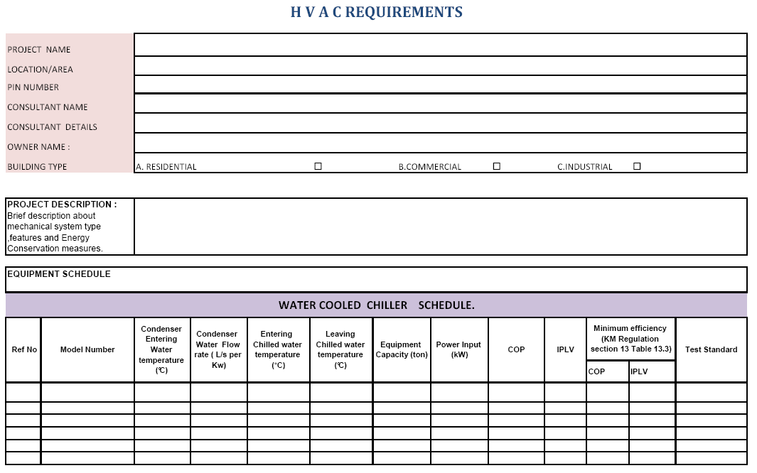
120 120
Unified requirements for systems with voltages above 1 kv up to 15 kv
 (1991) (Rev.1 May 2001) (Rev.2 July 2003) (Rev.3 Feb 2015) Unified requirements for systems with voltages above 1 kv up to 15 kv 1. General 1.1 Field of application The following requirements apply to
Electrical Practices for Construction Work
 1. Purpose Electrical Practices for Construction Work The purpose of this Code is to provide practical guidance and set minimum safety requirements for electrical practices on all construction sites in
3.1.1 Full Type Tests & Routine Tests according to Clause 8 2 & 8 3. 4.0 Instructions For Installation, Operation & Maintenance
 SPECIFICATION FOR LOW VOLTAGE SWITCHBOARD SEN I N D E X Description 10 STANDARD TECHNICAL REQUIREMENTS 11 Standards 12 General Operating Conditions 13 General Description Of Switchboard 131 Structure 132
Trade of Electrician. Three-phase Distribution Boards And Socket Circuits
 Trade of Electrician Standards Based Apprenticeship Three-phase Distribution Boards And Socket Circuits Phase 2 Module No. 2.3 Unit No. 2.3.2 COURSE NOTES Created by Charlie Walsh - Athlone TC Revision
FAQs-Main switchboard design criteria
 FAQs-Main switchboard design criteria Q: What is the Australian standard for main switchboards? Current Australian standard is AS/NZS 3439.1: 2002 originating from IEC 60439. The new series of standard
EARTHING AND BONDING AT SECONDARY SUBSTATIONS
 DISTRIBUTION CONSTRUCTION MANUAL SECTION 4 - SUBSTATIONS ISSUE B SEPT 1996 4.4.4 EARTHING AND BONDING AT SECONDARY SUBSTATIONS 1 SCOPE This section of the Distribution Construction Manual lays down the
Regulation IO-6.0: Electrical Safety Regulations
 Regulation IO-6.0: Electrical Safety Regulations 6.1 Workmanship & Material 6.2 Electrical Conductors 6.3 Overcurrent Protective Devices 6.4 Precautions against Earth Leakage and Earthfault Currents 6.5
Fire Protection Notice No. 9 ELECTRICAL SAFETY
 Fire Protection Notice No. 9 ELECTRICAL SAFETY Because electricity is one of the most controllable forms of energy it can also be one of the safest. But, as industry and commerce draw ever more heavily
DOMESTIC ELECTRICAL INSTALLATION CERTIFICATE (Requirements for Electrical Installations BS 7671 IEE Wiring Regulations)
") DOMESTIC ELECTRICAL INSTALLATION CERTIFICATE (Requirements for Electrical Installations BS 7671 IEE Wiring Regulations) DETAILS OF THE CLEINT Client and address ADDRESS OF THE INSTALLATION Installation
DOMESTIC ELECTRICAL INSTALLATION CERTIFICATE (Requirements for Electrical Installations BS 7671 IEE Wiring Regulations) DETAILS OF THE CLEINT Client and address ADDRESS OF THE INSTALLATION Installation
Trial Exams C. Standards and Regulations. Examination No: GH-08-C- 1 hour and 5 minutes plus 10 minutes reading time
 Trial Exams C Standards and Regulations Examination No: GH-08-C- This test is intended to gauge your knowledge of essential information contained within AS/CA S009:2013. To qualify for an allpication to
MEDIUM VOLTAGE CE-BF SWITCHBOARDS. UP TO 40.5 kv. CE - BF - C - en - REV.00 2012.4
 CE - BF - C - en - REV.00 2012.4 APPLICATION CE-BF Switchbords up to 40.5 kv are designed for use in public and industrial distribution system up to 40,5KV for the operation and protection of lines, transformers,
ELECTRICAL - WIRING DESIGN AND PROTECTION SELF INSPECTION CHECKLIST
 Name of School: OPTIONAL INFORMATION Date of Inspection: Vocational Program/Course/Room: Signature of Inspector: ELECTRICAL - WIRING DESIGN AND PROTECTION SELF INSPECTION CHECKLIST Guidelines: This checklist
ELECTRICAL GUIDELINES FOR SINGLE-FAMILY HOME OWNERS:
 ELECTRICAL GUIDELINES FOR SINGLE-FAMILY HOME OWNERS: Chapter 12 of the Burlington Code of ordinances allows owner occupants of single family homes to do their own wiring if they choose. If you choose to
Electrical for Detached Garages: Updated Feb 19, 2016 for 2015 CE Code in force Jan. 1, 2016. Underground branch circuit feeding a detached garage:
 Electrical for Detached Garages: Updated Feb 19, 2016 for 2015 CE Code in force Jan. 1, 2016 * Garage construction requires permits (electrical, building) * Permits must be applied for at the time. * Dial
Electrical Grounding. Appendix C
 Appendix C Electrical Grounding Low-Voltage Equipment Grounding The most frequently cited Office of Safety and Health Administration (OSHA) electrical violation is improper occupational grounding of equipment
Submit shop drawings for equipment provided under this section Shop drawings shall indicate:
 Section 16435 - SWITCHBOARDS Introduction Part 1 - General Reference The work under this section is subject to requirements of the Contract Documents including the General Conditions, Supplementary Conditions,
NZECP 14: 1995 ISSN 0114-0663 COVER PAGE
 NZECP 14: 1995 ISSN 0114-0663 COVER PAGE NZECP 14:1995 NEW ZEALAND ELECTRICAL CODE OF PRACTICE FOR CONTROL PROTECTION AND SWITCHBOARDS Issued by the Office of The Chief Electrical Engineer, Energy and
GROWTH MANAGEMENT DEPARTMENT 201 SE 3 rd ST, (Second Floor), Ocala, FL 34471 (352) 629-8421; FAX: (352) 629-8264
, Ocala, FL 34471 (352) 629-8421; FAX: (352) 629-8264") BUILDING CODE GUIDELINES FOR ELECTRICAL INSPECTIONS Building Code compliance is the obligation of design professionals and/or contractors. Plan Review and Inspection Guidelines are intended to be used
BUILDING CODE GUIDELINES FOR ELECTRICAL INSPECTIONS Building Code compliance is the obligation of design professionals and/or contractors. Plan Review and Inspection Guidelines are intended to be used
SOLAR PV STANDARD ELECTRICAL PLAN Microinverter Systems for Single Family Dwellings
 *** Provide this document to the inspector along with ALL system installation instructions *** Project Address: Scope: Standard plan for the installation of grounded microinverter solar PV systems, not
LV MCC LOW VOLTAGE SWITCHGEAR MOTOR CONTROL CENTRE PRODUCT GUIDE
 LV MCC LOW VOLTAGE SWITCHGEAR MOTOR CONTROL CENTRE PRODUCT GUIDE 380/415/690 Volt AC 50/65/80/100 ka 1. Product Guide Low Voltage Motor Control Centre CONTSTRUCTION Continuous "poured in place" gasket
Electrical Safety Tips. Help us keep you safe
 Electrical Safety Tips Help us keep you safe To help you stay safe when using electricity, ActewAGL has compiled these electrical safety tips. For natural gas safety tips please see ActewAGL s natural
6.0 Electrical Installations
 6.0 An electrical installation is a combination of electrical equipment installed to fulfill a specific purpose and having coordinated characteristics. In dealing with the electrical installation, it is
ESP 120 M1, ESP 208 M1, ESP 240 M1, ESP 415 M1, ESP 277 M1, ESP 480 M1 and M1R variants. Installation instructions ESP M1/M1R mains protectors
 ESP 120 M1, ESP 208 M1, ESP 240 M1, ESP 415 M1, ESP 277 M1, ESP 480 M1 and M1R variants Installation instructions Contents Key points of installation Before installation Installation Installation check
TIG INVERTER INSTRUCTION MANUAL
 TIG INVERTER INSTRUCTION MANUAL Contents Warning General Description Block Diagram Main Parameters Circuit Diagram Installation and Operation Caution Maintenance Spare Parts List Troubleshooting 3 4 4
12 SOLAR PHOTOVOLTAIC POWER SUPPLY SYSTEMS by John Ware. PV modules are current-limiting
 12 SOLAR PHOTOVOLTAIC POWER by John Ware IT IS PLANNED for BS 7671:2008 to include a new Section 712 providing additional requirements for safety applicable to solar photovoltaic (pv) power supply systems.
INTERNATIONAL STANDARD
 IEC 61892-7 INTERNATIONAL STANDARD Edition 2.0 2007-11 Mobile and fixed offshore units Electrical installations Part 7: Hazardous areas INTERNATIONAL ELECTROTECHNICAL COMMISSION PRICE CODE XA ICS 47.020.60
2014 NEC Guide Lines for Home Owner Doing Electrical Work on their Property
 2014 NEC Guide Lines for Home Owner Doing Electrical Work on their Property A brief summary of the most used code references for residential wiring State of Idaho Division of Building Safety Electrical
All work must conform to the National Electric Code, latest edition, and all other applicable codes and regulations.
 DIVISION 16 ELECTRICAL SECTION 16100 - ELECTRICAL PART 1 - GENERAL SCOPE All electrical work as shown on the drawings and as necessary to provide a complete electrical system. Include primary service,
DEPARTMENT OF LICENSING AND REGULATORY AFFAIRS DIRECTOR S OFFICE CONSTRUCTION SAFETY STANDARDS
 MIOSHA-STD-1313 (10/15) 6 Pages For further information Ph: 517-284-7740 www.michigan.gov/mioshastandards DEPARTMENT OF LICENSING AND REGULATORY AFFAIRS DIRECTOR S OFFICE CONSTRUCTION SAFETY STANDARDS
Heading FACT SHEET. Overview. www.safeworkaustralia.gov.au
 ELECTRICAL RISKS AT THE WORKPLACE Heading FACT SHEET Overview This fact sheet provides general guidance for persons conducting a business or undertaking (PCBUs) and workers on managing electrical risks
CHAPTER 4 UTILITY SYSTEMS ELECTRICAL. Utility Systems Electrical. Main Panel
 CHAPTER 4 UTILITY SYSTEMS ELECTRICAL Utility Systems Electrical The electrical supply to your home begins outside, where you will see either an overhead feed and piping down the side of your home or (if
Electrical Shore Connections / Cold Ironing
 STANDARD FOR CERTIFICATION No. 2.25 Electrical Shore Connections / Cold Ironing JULY 2014 The electronic pdf version of this document found through http://www.dnv.com is the officially binding version
INFRARED QUARTZ WALL HEATER
 INFRARED QUARTZ WALL HEATER MODEL NO: IQ2000 PART NO: 6939004 MOUNTING & OPERATION INSTRUCTIONS GC0715 INTRODUCTION Thank you for purchasing this CLARKE Infrared Wall Heater. Before attempting to use this
REVIEWED BY CAPITAL PROJECTS MANAGER (DAN REDDY) GENERAL MANAGER EQUIPMENT ENGINEERING & ASSET MANAGEMENT (HAMILTON NXUMALO)
 GENERAL MANAGER EQUIPMENT ENGINEERING & ASSET MANAGEMENT (HAMILTON NXUMALO)") SA Port Operations DOCUMENT TYPE: REFERENCE EEAM-Q-014 (ORIGINAL SPECIFICATION HE8.2.3 Ver5) REVISION 0 SPECIFICATION TITLE: SPECIFICATION FOR ELECTRICAL MOTORS AND GENERATORS PAGE 0 of 07 COMPILED BY
SA Port Operations DOCUMENT TYPE: REFERENCE EEAM-Q-014 (ORIGINAL SPECIFICATION HE8.2.3 Ver5) REVISION 0 SPECIFICATION TITLE: SPECIFICATION FOR ELECTRICAL MOTORS AND GENERATORS PAGE 0 of 07 COMPILED BY
DF-DT (G) MEDIUM VOLTAGE SWITCHGEAR THE MODULAR CONCEPT. User Manual. SGC - SwitchGear Company nv - Moorstraat 24 - B-9850 Nevele - Belgium
 MEDIUM VOLTAGE SWITCHGEAR THE MODULAR CONCEPT. User Manual. SGC - SwitchGear Company nv - Moorstraat 24 - B-9850 Nevele - Belgium") DF-DT (G) MEDIUM VOLTAGE SWITCHGEAR THE MODULAR CONCEPT User Manual SGC - SwitchGear Company nv - Moorstraat 24 - B-9850 Nevele - Belgium +32 (0)9/321.91.12 - Fax +32 (0)9/321.91.13 - e-mail: info@switchgearcompany.eu
DF-DT (G) MEDIUM VOLTAGE SWITCHGEAR THE MODULAR CONCEPT User Manual SGC - SwitchGear Company nv - Moorstraat 24 - B-9850 Nevele - Belgium +32 (0)9/321.91.12 - Fax +32 (0)9/321.91.13 - e-mail: info@switchgearcompany.eu
What are the basic electrical safety issues and remedies in solar photovoltaic installations?
 What are the basic electrical safety issues and remedies in solar photovoltaic installations? Presented by: Behzad Eghtesady City of Los Angeles Department of Building and Safety Topics Covered Photovoltaic
SECTION 26 09 13 - POWER MONITOR FOR ELECTRICAL, STEAM CONDENSATE, AND WATER PART I - GENERAL
 SECTION 26 09 13 - POWER MONITOR FOR ELECTRICAL, STEAM CONDENSATE, AND WATER PART I - GENERAL 1.1 SUMMARY A. This section describes the requirements for the installation of Power Monitors and associated
David O Brien, CMP Products (David.OBrien@cmp-products.com)
") David O Brien, CMP Products (David.OBrien@cmp-products.com) 1) Main Function of Cable Glands 2) Common Issues with Cable Glands 3) Compliance / Standards, changing times 4) How do we select Cable Glands?
David O Brien, CMP Products (David.OBrien@cmp-products.com) 1) Main Function of Cable Glands 2) Common Issues with Cable Glands 3) Compliance / Standards, changing times 4) How do we select Cable Glands?
RESIDENTIAL ELECTRICAL REQUIREMENTS (REVISED 3/28/2008) PERMIT REQUIREMENTS:
 PERMIT REQUIREMENTS:") RESIDENTIAL ELECTRICAL REQUIREMENTS (REVISED 3/28/2008) PERMIT REQUIREMENTS: Signed completed Electrical Permit application form. Minnesota law requires all electrical work is to be performed by licensed,
RESIDENTIAL ELECTRICAL REQUIREMENTS (REVISED 3/28/2008) PERMIT REQUIREMENTS: Signed completed Electrical Permit application form. Minnesota law requires all electrical work is to be performed by licensed,
Switchgear and Metal-Enclosed Bus
 Section 18 Switchgear and Metal-Enclosed Bus 180. SWITCHGEAR ASSEMBLIES 180A. General Requirements for All Switchgear. This rule covers general requirements for all switchgear. Examples of switchgear found
Circuit Electrical Testing
 Safe Isolation Procedure Circuit Electrical Testing Site Safety Management It is essential from the outset that effective management and control of the system, apparatus and equipment used on site is achieved
REB 1 REB 3 REB 5 REB 6 REB 8 REB 10 REB 12 REB 16
 REB 1 REB 3 REB 5 REB 6 REB 8 REB 10 REB 12 REB 16 Manually Operated Electronic Speed Controller Single Phase For all applications using suitably specified single-phase induction motor fans 1 GENERAL The
FFI. Advances in Medium and Low Voltage Power Distribution ESS Metron Expo and Technical Seminars. Presented By: Greg Pelster & Robert Schmid
 Advances in Medium and Low Voltage Power Distribution ESS Metron Expo and Technical Seminars Presented By: Greg Pelster & Robert Schmid FFI Ferrie, Franzmann Industries LOW VOLTAGE SWITCHGEAR & LOW VOLTAGE
1. Electrical Equipment A) Transformer
 Transformer") Standards and Basic Equipment Date : 15 November 2010 1. Electrical Equipment 2. Terminology 3. Code & Standard 1. Electrical Equipment A) Transformer A1) One Transformer and 11kV Switchgear in High Rise
Standards and Basic Equipment Date : 15 November 2010 1. Electrical Equipment 2. Terminology 3. Code & Standard 1. Electrical Equipment A) Transformer A1) One Transformer and 11kV Switchgear in High Rise
Comparative study for cables and busbars
 Comparative study for cables and busbars Preliminary considerations To compare the prices of two categories of product as different as traditional cables and busbars, it is necessary to make some preliminary
ELECTRICAL INSULATION TESTING OF HV EQUIPMENT UP TO 33kV
 1. SCOPE This document details PowerSystems requirements for electrical testing of HV Equipment up to and including 33kV. 2. ISSUE RECORD This is a Reference document. The current version of Controlled
2a. IEM Indoor Metal Clad Medium Voltage Switchgear 15KV 16346-1. 2a. Section 16346 INDOOR METAL CLAD MEDIUM VOLTAGE SWTICHGEAR (Std.
 2a. IEM Indoor Metal Clad Medium Voltage Switchgear 15KV 16346-1 2a. Section 16346 INDOOR METAL CLAD MEDIUM VOLTAGE SWTICHGEAR (Std. Relays) Part 1 General 1.1 CONDITIONS AND REQUIREMENTS: A. Refer to
ELECTRICAL SAFETY. The standard unit for measuring electrical current.
 ELECTRICAL SAFETY Introduction The following sections provide general safety guidelines and procedures for electrical safety. This chapter covers the following topics: TOPIC PAGE General Electrical Safety
ANCILLARY EQUIPMENT AND ELECTRICAL EQUIPMENT Power Supply Systems and Electrical Equipment for Desalination Plants - Y.M. Hamud and A.H.
 POWER SUPPLY SYSTEMS AND ELECTRICAL EQUIPMENT FOR DESALINATION PLANTS Y.M. Hamud and A.H. Anwar Abu Dhabi Water and Electricity Authority, Abu Dhabi, UAE Keywords : Electrical System, Network for Desalination,
USER INSTRUCTIONS FOR GET PORTABLE 12k BTU AIR CONDITIONER MODEL No. GPACU12HR
 USER INSTRUCTIONS FOR GET PORTABLE 12k BTU AIR CONDITIONER MODEL No. GPACU12HR CONTENTS Introduction Safety Notes Identification of parts Installation instructions Operation instructions Maintenance Troubleshooting
Portable Air Conditioner
 Portable Air Conditioner Owner's Manual Model:3 in 1 12,000 Btu/h Series 3 Please read this owner s manual carefully before operation and retain it for future reference. CONTENTS 1. SUMMARY...1 2. PORTABLE
PROTECTION AGAINST ELECTRIC SHOCK by John Ware
 16 become live under fault conditions. The potential of the metal enclosure is higher than that of the main earthing terminal of the installation (and that of Earth) because of a potential difference created
City of Riverside Building & Safety Division Phone: (951) 826-5697 www.riversideca.gov
 826-5697 www.riversideca.gov") City of Riverside Building & Safety Division Phone: (951) 826-5697 www.riversideca.gov PHOTOVOLTAIC PERMITTING GUIDELINES The information provided in this document is general and is intended only as a
City of Riverside Building & Safety Division Phone: (951) 826-5697 www.riversideca.gov PHOTOVOLTAIC PERMITTING GUIDELINES The information provided in this document is general and is intended only as a
Union County Public Schools. Facilities Department. Electrical. Safe Work Practices
 1 Union County Public Schools Facilities Department Electrical Safe Work Practices 2 Purpose In accordance with OSHA Standards 1910.331-335, safety-related work practices shall be used by Union County
Advantium 2 Plus Alarm
 ADI 9510-B Advantium 2 Plus Alarm INSTALLATION AND OPERATING INSTRUCTIONS Carefully Read These Instructions Before Operating Carefully Read These Controls Corporation of America 1501 Harpers Road Virginia
Homeowner Information Guide Electrical Safety. British Columbia Safety Authority
 Homeowner Information Guide Electrical Safety British Columbia Safety Authority The following information should be carefully reviewed before performing any electrical work. The information contained in
Current valve. for AC 24 V pulse/pause control of electrical loads up to 30 kw
 4 937 DESIO Current valve for AC 24 V pulse/pause control of electrical loads up to 30 kw SEA45.1 Use The current valve is used for the control of electric heating elements in heating, ventilation and
Title: Grounding and Bonding Rev-01
 Procedure No.: BMEHS-002-012 Page: 1 of 12 Preparer: Owner: Approver: EHS Team Member S/H Manager Site Manager Signed Copy on File Signed Copy on File Signed Copy on File Document Revision Change Table
Split-type Air-Conditioner INSTALLATION MANUAL CONTENTS FOR INSTALLER MXZ-3A30NA MXZ-4A36NA ATTENTION. English. Français. Español
 Split-type Air-Conditioner MXZ-3A30NA MXZ-4A36NA INSTALLATION MANUAL Refer to the installation manual of each indoor unit for indoor unit installation. English Français Español ATTENTION This manual mentions
4 IX D N E P P A Installation methods Current-carrying capacity and voltage drop for cables Reference method IET Wiring Matters
 8 Appendix 4 of BS 7671 by Mark Coles Appendix 4, Current-carrying capacity and voltage drop for cables and flexible cords, has seen significant changes with the publishing of BS 7671:2008. This article
INSTALLATION GUIDELINES for SOLAR PHOTOVOLTAIC SYSTEMS 1
 City of Cotati Building Division 201 W. Sierra Ave. Cotati, CA 94931 707 665-3637 Fax 792-4604 INSTALLATION GUIDELINES for SOLAR PHOTOVOLTAIC SYSTEMS 1 Any PV system on a new structures should be included
GUIDE TO THE MAINTENANCE, INSPECTION AND TESTING OF PORTABLE EQUIPMENT (ELECTRICAL APPLIANCES AND TOOLS) IN THE WORKPLACE
 IN THE WORKPLACE") GUIDE TO THE MAINTENANCE, INSPECTION AND TESTING OF PORTABLE EQUIPMENT (ELECTRICAL APPLIANCES AND TOOLS) IN THE WORKPLACE ET 215:2008 ELECTRO-TECHNICAL COUNCIL OF IRELAND 2008 Page 1 of 6 Published by
GUIDE TO THE MAINTENANCE, INSPECTION AND TESTING OF PORTABLE EQUIPMENT (ELECTRICAL APPLIANCES AND TOOLS) IN THE WORKPLACE ET 215:2008 ELECTRO-TECHNICAL COUNCIL OF IRELAND 2008 Page 1 of 6 Published by
Questions and Answers for Heating and A/C Contractors
 1. How do we accomplish grounding of furnaces and / or water heaters on two wire circuits? 250.134 Equipment Fastened in Place or Connected by Permanent Wiring Methods (Fixed) Grounding. Unless grounded
Pressure monitoring equipment for oil-sf 6. bushings, type GOEK
 Pressure monitoring equipment for oil-sf 6 bushings, type GOEK Installation and maintenance guide 5693 827-6 en, Rev. 3, 2002-01-30 This document must not be copied without our written permission, and
REPLACEMENT AIR CONDITIONING UNITS FOR BRITISH EMBASSY RESIDENCE
 REPLACEMENT AIR CONDITIONING UNITS FOR BRITISH EMBASSY RESIDENCE FOREIGN & COMMENWEALTH OFFICE BE BAHRAIN TEL: MAY 2014 EMAIL: TENDER ISSUE: 002/2014 1. GENERAL REQUIREMENTS 1.01 LOCATION OF SITE The British
ELECTRICAL CONTRACTORS THE UNIVERSITY OF TENNESSEE KNOXVILLE, TENNESSEE SECTION 16050 PAGE 1
 KNOXVILLE, TENNESSEE SECTION 16050 PAGE 1 PART 1 - GENERAL 1.01 RELATED DOCUMENTS: SECTION 16050 A. Drawings and general provisions of Contract, including General and Supplementary Conditions and Division-1
ALTERNATIVE METHODS FOR INTERNAL ARC TESTS ON 12 KV AND 24 KV METAL-ENCLOSED SWITCHGEARS WITH COMPACT RMU
 ALTERNATIVE METHODS FOR INTERNAL ARC TESTS ON 12 KV AND 24 KV METAL-ENCLOSED SWITCHGEARS WITH COMPACT RMU George CURCANU, Constantin ILINCA, Ilie SBORA ICMET Craiova, Romania, Calea Bucuresti 144, phone:
ELECTRICAL SAFETY Information Bulletin
 ELECTRICAL SAFETY Information Bulletin January 2016 CEC-10 [rev-9] Page 1 of 8 CANADIAN ELECTRICAL CODE SUBJECT: Section 10 Grounding and Bonding Rule 10-204 Grounding Connections for Alternating-Current
DRM75A 230V 20/100A DIN rail single phase two wire energy meter
 DRM75A 230V 20/100A DIN rail single phase two wire energy meter 1.1 Safety instruction 1.2 Foreword 1.3 Performance criteria 1.4 Specifications 1.5 Basic errors 1.6 Description 1.7 Dimensions 1.8 Installation
Outdoor 33.6W Dual Port Passive Power-over-Ethernet Midspan For External Security Cameras and Wireless Access Points
 Outdoor 33.6W Dual Port Passive Power-over-Ethernet Midspan For External Security Cameras and Wireless Access Points Features SELV Compliant No Detection Passive Injector Gigabit Compatible Full Protection
ADM1TE 5/30A DIN rail single phase two wire energy meter
 ADMTE 5/30A DIN rail single phase two wire energy meter. Safety instruction.2 Foreword.3 Performance criteria.4 Specifications.5 Basic errors.6 Description.7 Dimensions.8 Installation.9 Operating.0 Troubleshooting.
32:(5#5$7,1* 4833#USP283#+] 4;33#USP293#+] 3ULPH 113 kva, 90 kw 124 kva, 99 kw 6WDQGE\ 114 kva, 91 kw 125 kva, 100 kw
![32:(5#5$7,1* 4833#USP283#+] 4;33#USP293#+] 3ULPH 113 kva, 90 kw 124 kva, 99 kw 6WDQGE\ 114 kva, 91 kw 125 kva, 100 kw](/thumbs/30/14614129.jpg "32:(5#5$7,1* 4833#USP283#+] 4;33#USP293#+] 3ULPH 113 kva, 90 kw 124 kva, 99 kw 6WDQGE\ 114 kva, 91 kw 125 kva, 100 kw") ,1'8675,$/#*(16(7 6HULHV#'9#448 32:(5#5$7,1* 4833#USP283#+] 4;33#USP293#+] 3ULPH 113 kva, 90 kw 124 kva, 99 kw 6WDQGE\ 114 kva, 91 kw 125 kva, 100 kw Generator set consisting of engine and alternator mounted
,1'8675,$/#*(16(7 6HULHV#'9#448 32:(5#5$7,1* 4833#USP283#+] 4;33#USP293#+] 3ULPH 113 kva, 90 kw 124 kva, 99 kw 6WDQGE\ 114 kva, 91 kw 125 kva, 100 kw Generator set consisting of engine and alternator mounted
Common Electrical Hazards in the Workplace Including Arc Flash. Presented by Ken Cohen, PhD, PE & CIH (Ret.)
") Common Electrical Hazards in the Workplace Including Arc Flash Presented by Ken Cohen, PhD, PE & CIH (Ret.) 1 What s New In February 1972, OSHA incorporated the 1971 edition of the National Fire Protection
Common Electrical Hazards in the Workplace Including Arc Flash Presented by Ken Cohen, PhD, PE & CIH (Ret.) 1 What s New In February 1972, OSHA incorporated the 1971 edition of the National Fire Protection
HIGH VOLTAGE SHORE CONNECTION
 Guide for High Voltage Shore Connection GUIDE FOR HIGH VOLTAGE SHORE CONNECTION NOVEMBER 2011 American Bureau of Shipping Incorporated by Act of Legislature of the State of New York 1862 Copyright 2011
AS/NZS 3000:2007 Amendment 2
 AS/NZS 3000:2007 Amendment 2 Published 14 December 2012 Under Victorian legislation the day a revised standard is published it becomes the requirement. The aim of this document is to highlight the important
Addendum #2 Contract UK-11-13
 Addendum #2 Contract UK-11-13 Utilities Kingston Purchase and Replacement of Switchgear at Kingston Hydro Substation MS11 March 25, 2011 Delivered to: All RFP recipients Total number of pages: Nine (9)
TECHNICAL SPECIFICATIONS & SPECIAL CONDITIONS OF CONTRACT FOR ELECTRICAL WORKS CHAPTER 1 SPECIAL CONDITIONS OF CONTRACT
 TECHNICAL SPECIFICATIONS & SPECIAL CONDITIONS OF CONTRACT FOR ELECTRICAL WORKS CHAPTER 1 SPECIAL CONDITIONS OF CONTRACT 1.1 General 1.1.1 These Special Conditions of Contract supplement the General Instructions.
High Voltage (HV) Electricity System Safety Rules and Associated Safety Guidance
 Electricity System Safety Rules and Associated Safety Guidance") Annex I To Loughborough University (LU) Facilities Management (FM) Health and Safety Policy High Voltage (HV) Electricity System Safety Rules and Associated Safety Guidance 1. Introduction a. These Safety
Annex I To Loughborough University (LU) Facilities Management (FM) Health and Safety Policy High Voltage (HV) Electricity System Safety Rules and Associated Safety Guidance 1. Introduction a. These Safety
Operating Instructions
 Operating Instructions Cable Glands Ex d and Ex e with Compound > Contents 1 Contents 1 Contents...2 2 General Information...2 3 General Safety Information...3 4 Designated Use...4 5 Technical Data...4
26 3213.13 Diesel Engine Driven Generators Page 1 of 6
 Last Update: December 8, 2014 A. Description of System Consultant s Handbook Page 1 of 6 1. Provide a diesel engine driven electric generating unit, factory assembled, tested and certified to operate at
ELECTRICAL PRACTICES FOR CONSTRUCTION WORK
 CONTRACTOR S CHECKLIST ELECTRICAL PRACTICES FOR CONSTRUCTION WORK 2007 WorkCover. Watching out for you. New South Wales Government Disclaimer This publication contains information regarding occupational
Our brand POWER DYNAMIC PASSION COMMITMENT CREATIVITY. A strong brand for strong products: 8PU Premium. MV Energy
 Our brand A strong brand for strong products: The ENERGOLINE brand represents our product portfolio of INDUSTRIAL SWITCHGEAR SYSTEMS. Our products are characterized by a high degree of safety, flexibility
MCR1900 Media Converter 19-Slot Chassis
 MCR1900 Media Converter 19-Slot Chassis Installation Guide Part #5500304-11 Copyright Statement This document must not be reproduced in any way whatsoever, either printed or electronically, without the
Sample - No Commercial Use
 COMPLETE REVISION October 2010 Electrical PIP ELSSG01 Design and Fabrication of Low-Voltage Metal-Enclosed AC Power Circuit Breaker Switchgear PURPOSE AND USE OF PROCESS INDUSTRY PRACTICES In an effort
Electrical Resistance Resistance (R)
") Electrical Resistance Resistance (R) Any device in a circuit which converts electrical energy into some other form impedes the current. The device which converts electrical energy to heat energy is termed
Electrical Resistance Resistance (R) Any device in a circuit which converts electrical energy into some other form impedes the current. The device which converts electrical energy to heat energy is termed
33.6W Power over Ethernet Waterproof Adapter PoE Plus Single Port Injector for Outdoor Application
 33.6W Power over Ethernet Waterproof Adapter PoE Plus Single Port Injector for Outdoor Application Features Compliant with the IEEE802.3at Standard -40 to +60 C Temperature Range Diagnostic LEDs Full Protection
PLEASE NOTE. For more information concerning the history of these regulations, please see the Table of Regulations.
 PLEASE NOTE This document, prepared by the Legislative Counsel Office, is an office consolidation of this regulation, current to August 1, 2013. It is intended for information and reference purposes only.
Explosion proof enclosures
 1 of 7 Explosion proof enclosures DE8 C 2 of 7 The Ex d enclosures are rugged and designed for harsh environment like: Oil and gas industry Chemical industry Pharmaceutical industry Agribusiness Without
EVC40 EMERGENCY VOICE COMMUNICATION SYSTEM
 EVC40 EMERGENCY VOICE COMMUNICATION SYSTEM INSTALLATION MANUAL Protec Fire Detection PLC, Protec House, Churchill Way, Nelson, Lancashire, BB9 6RT. Telephone: +44 (0) 1282 717171 Fax: +44 (0) 1282 717273
Fundamentals of Power
 Fundamentals of Power Fundamentals of Power 2008 American Power Conversion Corporation. All rights reserved. All trademarks provided are the property of their respective owners. Learning Objectives At
chapter8 Testing and commissioning Unit 2 outcome 2
 Testing and commissioning chapter8 Unit 2 outcome 2 It is important that electricians are not just able to construct; they should also be able to recognise faults and take action to help prevent them.
Oil and Coolant Circulating Heating System. Model - OCSM
 Oil and Coolant Circulating Heating System Model - OCSM Installation & Operation Manual 216280-000 REV 2 Identifying Your System The HOTSTART heating system is designed to heat fluids for use in marine
ELECTRICAL INSTALLATION CONDITION REPORT (Requirements for Electrical Installations BS 7671 IEE Wiring Regulations)
") Original Certificate DETAILS OF THE CLIENT Certificate reference: ELECTRICAL INSTALLATION CONDITION REPORT (Requirements for Electrical Installations BS 7671 IEE Wiring Regulations) Name: Address: PURPOSE
Original Certificate DETAILS OF THE CLIENT Certificate reference: ELECTRICAL INSTALLATION CONDITION REPORT (Requirements for Electrical Installations BS 7671 IEE Wiring Regulations) Name: Address: PURPOSE
USER S MANUAL. MaxPower 400-600 UPS. Uninterruptible Power System 28-2MAXPO0018
 USER S MANUAL MaxPower 400-600 UPS Uninterruptible Power System 28-2MAXPO0018 IMPORTANT SAFETY INSTRUCTIONS SAVE THESE INSTRUCTIONS This manual contains important instructions for models MaxPower 400 and
1 Introduction. 2 Hazards From Electricity
 Risk Assessment Application to Electrical Rigs A guide to assist the Competent Named person who will verify the safety of rigs consisting mainly of electrical equipment. 1 Introduction Every employer shall
HAZARDS, INCLUDING SHOCK, ARC FLASH AND FIRE
 Appendix B-2 - Electrical Safety In Design Final Report TECHNOLOGIES THAT REDUCE LIKELIHOOD OF INJURY FROM ELECTRICAL HAZARDS, INCLUDING SHOCK, ARC FLASH AND FIRE The following are technologies that reduce
County of Riverside Building and Safety Department
 County of Riverside Building and Safety Department Mike Lara Director Photovoltaic Permitting Guidelines The information provided in this document is general and is intended only as a guide. Each project
METER REQUIREMENTS GENERAL REQUIREMENTS SECTION D
 12 - ELECTRIC SERVICE HANDBOOK SECTION D METER REQUIREMENTS This chapter gives you information on Central Lincoln s metering requirements. It's divided into three sections: General requirements This section
Guide to the Safety, Health and Welfare at Work (General Application) Regulations 2007. Part 3: Electricity
 Regulations 2007. Part 3: Electricity") Guide to the Safety, Health and Welfare at Work (General Application) Regulations 2007 Part 3: Electricity 9 Guide to the Safety, Health and Welfare at Work (General Application) Regulations 2007 Part
Guide to the Safety, Health and Welfare at Work (General Application) Regulations 2007 Part 3: Electricity 9 Guide to the Safety, Health and Welfare at Work (General Application) Regulations 2007 Part
The complete guide to Low Voltage switchgear
 The complete guide to Low Voltage switchgear The complete guide to low voltage switchgear Contents 4-7 Merlin Gerin LV Switchgear An introduction to the Merlin Gerin low voltage range of switchgear, and