How To Install A Doorbell Fon Unit
|
|
|
- Hortense Johns
- 3 years ago
- Views:
Transcription
1 Doorbell Fon User and Installation Manual Congratulations on purchasing your NEW DoorBell Fon intercom system. This device will provide you with the latest phone intercom system for years to come. It features simple installation and easy operation, bringing into your life security, peace of mind and convenience. The system works with your incoming regular telephone line, or it may be used as a stand-alone unit. It may also be linked to multi-line, PBX or Key systems. With the optional modules available to incorporate into the system, you have the ability to open door-locks, sound your doorbell chime, or change your home telephone system into an intercom system. The DoorBell Fon control unit requires only one connection from your incoming telephone line and one Door Station. A second Door Station may be added to the controller for another entryway, or add other modules to integrate into your system. Enclosed in this kit you will find: 1 - DP28C Controller 1 - User Guide (with warranty registration card) 1 - Door Station (Optional) This device is simple to install, but please follow this installation guide carefully. If the instructions are not followed and the unit is damaged, you may void your warranty. INDEX Installation Procedure Connection of your DoorBell Fon Main Controller...2 Connection of your DoorBell Fon Door Station...3 Installer s Notes.3 Powering up your DoorBell Fon Unit..3 Wiring Diagrams How to use Existing Doorbell Wires in a House Installation 4 DSL Wiring Diagram 5 VoIP Wiring Diagram...5 Door Strike Controller Wiring Diagram.6 Door Chime Controller Wiring Diagram 6 Operating Instructions and Q&A....7 Troubleshooting.8 Return for Repair Procedure.13 Warranty..15 1

2 INSTALLATION PROCEDURE Connection of your DoorBell Fon Main Controller Locate where your incoming phone line (POTS) enters your house. This is the location where you will connect the Main Controller (black box). This device will usually be the first device attached to your telephone line. If a there is a security system on the phone line, the DoorBell Fon Main Controller must go after the security system and before the phones. If you are using DSL or VoIP please refer to the Wiring Diagrams section for installation. You will need to cut the line after it enters your house: this is where you will attach the Main Controller. Once severed, connect this line to the controllers From TEL. Company position. (You may use the jack connectors or screw terminals; they both operate the same) Next, connect the other end of the line you cut, to the To Phones position. (Again, you may use the jack connectors or screw terminals; they both operate the same) Alternatively, you may disconnect the POTS line from your distribution panel and connect it to the From TEL. Company position and use fresh phone wires to connect the To Phones position back to the distribution panel. At this time, you may mount the controller in your desired location. Ideally the installation location should be in-between the phone line entering your house and distribution panel before the phones throughout the home. 2

3 Connection of your DoorBell Fon Door Station Find the best location to mount the Door Station. If the Door Station is the DP28-NIT or DP28-NWT model, remove the screw located at the bottom of the Door station. This will remove the Door Station from the mounting bracket. Mount the bracket at the desired location. You will notice there are two screws at the upper-left-hand corner on the back of your Door Station. Connect a pair of wires to these screws and run the length of wires to the location of the Main Controller (black box). Once you have run the wires to your controller, you may connect them to either Door 1 or Door 2 screw terminals on the black box. Please remember to observe proper polarity. Both Door 1 and Door 2 connections provide a different ring pattern; test both for your personal preference as to which one you prefer. After making the connections and you are satisfied with the ring pattern selected, mount the Door Station back onto the mounting bracket. INSTALLER NOTES: 1. Please Note: Our system is not compatible with Motorola Telephone systems. 2. Your customer may prefer the ring pattern on Door 2 rather than Door 1. There is no problem using either door connection. 3. You can connect in-series up to 4 Door Box Controllers together for a total of 8 zones. 4. If the Door Station polarity is wrong, the unit will ring, but there will be no communication and the Door Station LED will not glow at all. 5. If you are using the Intercom Module add-on, you can only use 1 Door Station and only on the Door 1 terminal. 6. Shorting the pair going to Door 1 or Door 2 will cause the unit to ring the phones and will not damage. Applying this, you can use an existing doorbell button in series with a 300 ohm resistor to ring the phones. 7. If you are installing To Phones to a telephone system, you will lose the distinctive ring between Door Stations 1 & 2, since you will then hear the phone system s ring when the button is pushed. You could purchase a Tone Generator, which would allow you to send the ring from the door over the customer s-existing paging system. This applies to most wireless phones as well. 8. Optional chips are available which will let the unit ring more (N8H), fewer times (N1H) or only connect to the To Phones of a PBX, KSU, or phone-set without a CO line to the From TEL. Company (N8NC). 9. There are two fuses on the circuit board. One for the phone line (F2) and the other for the AC power line (F1). 10. To determine if there are too many phones connected to the DoorBell Fon system, check the REN on all phones connected total the number. If it is above 4.6 then the REN is too high and there are too many phones. Older phones will have a higher REN than they are labeled as they age. 11. ACNC/DoorBell Fon highly recommends installation of Lightning Surge Protection on the AC circuit and incoming phone line. Lighting damage is not cover by the warranty. Powering up your DoorBell Fon unit Once your connections are secured and checked, you may power up the unit by plugging the controller cord into an 110V outlet. Once the unit is powered up, the LED light on the Door Station should glow dimly if the polarity is correct. If it does not, then the wires were not connected properly. Double check the polarity of the two wires, make sure that the (+) is connected to (+) and ( ) is connected to ( ). If you have followed the instructions carefully and your DoorBell Fon system is not working properly, please refer to the trouble-shooting page for assistance. 3
.")
4 WIRING DIAGRAMS 4

5 5

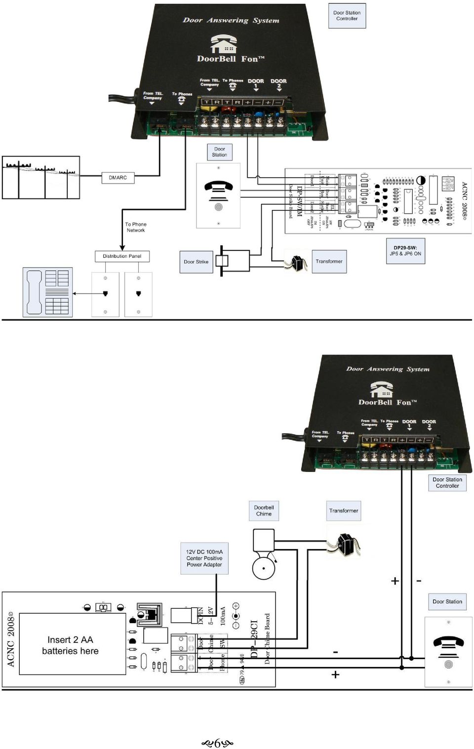
6 6
7 OPERATING INSTRUCTIONS and Q & A Please read over the following Q & A section to help you with the normal operations of this product. How do I answer my door or gate? Simply pick up your telephone. You will automatically be connected with the Door Station. The controller will determine which Door Station is calling if there are more than one. What if I pick-up the phone after it stopped ringing? The DoorBell Fon will ring your telephone within a series of 3 distinctive rings. If it is not picked up after the last series of rings you will have approximately 25 seconds to pick up the phone and press the flash key (hook switch if no flash key is present) to connect to the Door Station. What if I m on the phone when someone comes to my door? The DoorBell Fon has built-in call waiting. If you are on the telephone and someone pushes the button on the Door Station, you will hear its signal on your telephone. Simply press the flash or hook switch on your receiver and you will be talking to the door. When you are finished talking to the Door Station, just press the flash button, or hook switch on your receiver and you will be connected back to the call that was on hold. Will the DoorBell Fon affect my answering machine? The DoorBell Fon will not affect the normal operations of your answering machine. If you wish for your answering machine to answer your door, simply set the answering machine to 2 rings. If not set the answering machine to over 3 rings. How will I know if it is an outside line or a door when my telephone rings? The DoorBell Fon generates its own ring pattern for both Door 1 and Door 2 positions. You can distinguish the difference in rings by the duration of the rings. A normal ring pattern is 1 second on and 2 seconds off. Door 1 has a pattern of 1 second on and 1 second off. Door 2 has a pattern of 1 second on, ½ second off, 1 second on and 1 second off. The volume is too low or high on the Brass or Aluminum Door Stations! How can I adjust the level? There is a potentiometer on one side of the pc-board of the Door Station. Turn it clockwise slightly to adjust the volume level to your preferred settings. Generally, factory setting will already be at maximum volume. If the volume is low, please refer to the troubleshooting section. 7
 to connect to the")
8 Can the DoorBell Fon open my door for me? Yes, the DP29-SW/IM add-on controller will allow you to open any electric door or gate by pressing the (*) button on your phone keypad. How many phones can I connect to the DoorBell Fon? There is no specific number of phones. The number is based on the Ringer Equivalency Number (REN) of all the devices connected to your telephone line. The maximum operating ranges for the DoorBell Fon is 4.6 to 5.0. You can calculate the total number by looking at the labeling on the bottom of all your telephones, caller ID units and answering machines. Please note that older, hardwired phones usually have an actual REN greater than the printed value as the REN value rises over time. This number is a FCC Certification approving a telephone terminal product for direct sale to the end user. The REN number consists of a letter and a number. Total all of the numbers on all telephones, caller ID units and answering machines. If this number is exceeded, you may have to purchase a 'Ring Booster'. What if I hear a dial-tone in the background when I answer the Door Station? The installation is wrong! The DoorBell Fon's Controller should be the first in series before all other phones in your home. TROUBLE SHOOTING When I press the Door Station button, the phone will ring; however, I cannot talk on the phone. If this is a new installation, check to see if the LED light becomes brighter when the Door Station button is pushed. If it does not, check the (+) and (-) connections on the DoorBell Fon Main Controller (black box). This device is polarity sensitive, so make sure the (+) and (-) connections are not reversed. If this is an old installation that use to work, the Door Station might have a faulty microphone or speaker. Contact ACNC Customer Service for replacement parts. I can communicate with the Door Station, but I cannot get a dial-tone when I pick up the handset of the telephone. Unplug the power of the controller. If there is still no dial-tone, check the fuses inside the controller. Replace if necessary. F1 is a 0.5A/250V electrical fuse and F2 is a 0.25A/250V phone fuse. 0.5A/250V may be used for F2 as well. While unplugging the DoorBell Fon controller listen for a dial tone. While powering up the controller again, pick up the phone handset. If you get the Door Station instead of the dial-tone, then your phone set is a non-standard phone set. Non- 8

9 standard phone sets will send an incorrect signal to the DoorBell Fon controller. You must replace the phone set to get dial-tone. My Caller ID will not work with the DoorBell Fon. The Caller ID will not display anything when a Door Station rings your phones. Normal phone calls should still function normally. The problem might be caused by the total REN (Ring Equivalency Number) of all your telephone devices (answering machine, caller ID, phone sets.) The total REN should be under 4.6. If the total is over 4.6, you will need a Ring Booster. If the REN is less than 4.6, replace the F2 phone fuse in the DoorBell Fon Main Controller with a 2AG 0.25A or 0.5A fast blow fuse. When the DoorBell Fon is pressed, there is static on the line. Unplug the controller. Turn the plug 180 degrees and plug it back in after 10 seconds. If you have DSL, the data and phone signal must be split before entering the Main Controller. The phone signal will go the Main Controller and the data signal will bypass the Main Controller and go to the internet modem. If you have an alarm system, it needs to be installed in series before the Main Controller on the phone line. If none of these steps work or do not apply, please contact ACNC Customer Support. My phone will not ring. Switch the Tip (T) and the Ring (R) at the To Phones terminal on the DP28-C. Some phones are polarity sensitive. Pick up the telephone handset and press the flash key or hook switch to attempt communication with the Door Station. If there is communication, then your total REN is most likely over 4.6 and a ring booster is needed. If you are not able to communicate with the Door Station, please go to the DoorBell Fon Main Controller and quickly short the 2 screws connected to the Door Station with a jumper wire or paper clip. If the phones ring, please check the connection between the Door Station and Main Controller. At the Main Controller, disconnect wires coming from terminals labeled To Phones. Check all the phones in the house for dial tone. If there is dial tone present on any of the phones, please double check all telephone wiring to make sure dial passes through only the Main Controller before reaching the phones. Connect a single basic, corded analog phone set directly to the Main Controller. Press the Door Station button to ring the phone. If the phone does not ring, short the Door Station screw terminal at the Controller. If the phone rings, please double check all wire connections. If none if these steps you work, the Main Controller might be faulty. My Door Station makes a funny noise, almost like a motorboat. This is most likely normal, if it is not a high pitch squealing motorboat sound. 9

10 My Door Station makes a squealing noise or gets a lot of feedback. If the Door Station faceplate is metal, please make sure the plastic film cover has been removed. Locate the R11 potentiometer on the Door Station circuit board. Turn the screw counter-clockwise until squealing or feedback disappears. Place foam or insulation inside the Door Station mounting box. If the Door Station is the DP28-NIT or DP28-NWT model, please make sure the Door Station is not installed by the corner of a wall. Contact ACNC Customer Service if these steps do not solve your problem. I am having volume problems with my Door Station. If the Door Station faceplate is metal, locate the R11 potentiometer on the Door Station circuit board. Turn the screw counter-clockwise to lower the volume and clockwise to raise it. Temporarily install the Door Station directly at the Main Controller. If the volume is normal, please check the wires. Do not double up on wires for each lead. People inside cannot hear the people outside and/or people outside cannot hear the people inside The Door Station microphone, speaker, or circuit board might be faulty. Please contact ACNC Customer Support about replacements. When I answer an incoming call, I get the Door Station instead of the incoming call. Reverse the tip and ring wires (usually green and red) in the telephone wall outlet. If the problem persists, the phone set is likely a non-standard phone set. Please replace the phone set or contact ACNC Customer Service for a special replacement chip. All of my phones ring except my answering machine or cordless phone. Check to make sure that section of the house is properly connected to the DoorBell Fon Main Controller at the distribution panel. Reverse the tip and ring wires (usually green and red) of that telephone s wall outlet. The LED on the Door Station is always brightly lit. If the phones are not constantly ringing, the Main Controller or Door Station or both might need to be replaced. THE LED on the Door Station does not light up. Check the Door Station (+) and (-) connections. The LED will not light if the polarity is incorrect Check the F1 fuse inside the Main Controller. Replace if necessary. Contact ACNC Customer Service if these steps do not resolve the issue. 10

11 I am using the Telephone Keypad Relay Trigger/Door Strike Controller. When I press the (*) key, my electric/magnetic lock will not open. Please verify that the DIP switch is programmed to the desired key. The (*) key code is (up, down, up, up). If using a magnetic lock, please change JP4 from Normally Open (NO) to Normally Closed (NC). If using a standard corded phone, please hold the (*) key to extend the signal. If using a cordless phone, please press the (*) at least 3 times quickly. My phone rings back after I release my electric lock/gate and hang up the phone. Please allow at least 1 second after activating the electric lock/gate and before hanging up the phone to allow the signal to finish. When I am on the phone and someone presses the Door Station, my phone call is cut off instead of receiving the call-waiting tone. Test with a basic, corded analog phone set (not the phone where calls are being cut off) hooked up directly to the Main Controller in the phone jack labeled To Phones. If the phone call is not interrupted when the Door Station is pressed, then the other phone is a non-standard phone. If the problem persists with different phone sets, please contact ACNC Customer Service. The phone keeps ringing but no one is pushing the Door Station button. If a regular doorbell is being used instead of a Door Station, please remove any lights inside the doorbell. If any add-on components (DP29-SW/IM or DP29-CI) are being used, remove them one by one and see if the phones continue ringing. if the phones stop ringing, the last component removed is most likely defective. Disconnect all wires from Door 1 and Door 2 screw terminals. If ringing persists, either the Main Controller is defective or brown outs are occurring at the location. Replace Door Stations if the ringing stops. After installing a new chip, the phone line never gets released. Please reseat the new chip and make sure there are no bent pins. A regular doorbell switch is being used instead of a Door Station, but it does not work properly. A 330 ohm resistor must be placed in series with the doorbell button. The DoorBell FOn system needs to be hooked up to a PBX system. Please use a vacant FXO port instead of FXS. The FXO port is also known as the CO port or trunk line. 11

12 If there is no telephone company line connected tot eh Main Controller, please use a N8NC chip inside the Main Controller. Contact your DoorBell Fon dealer or ACNC Customer Support to order one. What are the expected terminal voltages on the Main Controller? How can I make my Door Chime ring when someone pushes the Door Station button? You can use the DP29-CI Inbound Relay Trigger to activate your Door Chime. This will make your phones ring as well as your Door Chime and can only be used with 1 Door Station per system. If I am using the DP29-CI to activate my Door Chime, how dod I keep my phones from ringing? Simply bend out pins 10 and 11 on the removable chip inside the DP28-C DoorBell Fon Main Controller. This will remove the phone rings as well as call-waiting while only the Door Chime rings. 12

13 RETURN for REPAIR PROCEDURE In order to make this procedure as easy as possible and to validate your two-year warranty, it is important to fill-out and mail your units Warranty Registration Card to ACNC as soon as possible. We highly recommend doing so after the installation of your new unit. Step 1 IMPORTANT: Please call ACNC Customer Service and describe the problem. Tell the Service Representative if your unit is covered under warranty. Our Representative will issue you a Return Merchandise Authorization (RMA) Number. However, if your unit is not registered, but covered under warranty, you will need to provide proof of the Date-of-Purchase. If your proof of purchase is not available, or your unit is not covered under warranty, you will incur set repair fees. Our Customer Service Representative will provide you with this information. Step 2 When sending the unit, please pack the unit in its original carton. If that is not available a sturdy corrugated cardboard box using NON-STATIC material is necessary. IMPORTANT: Please DO NOT USE highly static prone material such as plastic wrap, Styrofoam based packing materials (i.e. Peanuts, popcorn, or beads); this material may cause further damage to the unit(s) in transit. Please do not include, the User Guide and the original documentation. Step 3 Include the following information with your unit: Your Name Your Address Your Telephone Number (day or evening) Return Merchandise Authorization Number (RMA) Description of the problem Repair Fee* (if any) Step 4 Ship unit(s) prepaid via UPS or U.S. Postal Service. We recommend that the unit(s) be insured when shipped. ACNC WILL NOT accept C.O.D. Packages. *NOTE: ACNC will assess a charge if the previous items are not included in the shipment. Mail Package to: ACNC/Doorbell Fon Attn: Warranty/Repair Dept RMA# (include on mailing label) 1989 University Ln., Unit H Lisle, IL U.S.A. After repair or replacement, products will be shipped by ACNC at no cost to our customer(s) to any destination in the U.S.A, or its territories. Selection of carrier and method of shipment will be chosen by ACNC. If you desire another form of shipping, or 13

14 are located outside the Continental U.S. and its territories, you must pay for the cost of shipment plus any other incidental costs incurred. FOR TECHNICAL SUPPORT Telephone: Home Page:

15 WARRANTY ACNC warrants to the original purchaser that each of its hardware products and all components thereof will be free from defects in material and/or workmanship for one year from the date of purchase. Any warranty hereunder is extended only to the original purchaser and is not transferable. If product is REGISTERED, this warranty covers all labor and materials for a period of two years from original purchase date. In the event of a malfunction or other indication of failure, attributed to faulty workmanship and/or materials, ACNC will, at it's option, repair or replace the defective products or components to whatever extent it shall deem necessary to restore the product or component to proper operating condition, provided the product holds a valid warranty registration. This warranty excludes damage from power surges by Natural Causes (i.e. Lightning strikes) or improper installation. Damaged units will not be covered under this warranty and is the sole responsibility of the customer. ACNC holds the right to replace the defective product with a new or remanufactured functionally equivalent product of equal value. This warranty is in lieu of all other express warranties which now or hereafter might otherwise arise with the respect to this product. ANY AND ALL IMPLIED WARRANTIES OF MERCHANTABILITY AND FITNESS FOR PARTICULAR USE SHALL HAVE NO GREATER DURATION THAN THE PERIOD FOR THE EXPRESS WRITTEN WARRANTY APPLICABLE OF SUCH PERIOD. Some states do not allow limitations on how long an implied warranty lasts, so this limitation may not apply to you. No action shall be brought for breach of any implied or express written warranty. The customer shall be solely responsible for the failure of any ACNC product or component thereof; resulting from accident, abuse, or misapplications of the product, and ACNC assumes no liability as a consequence of such events under the terms of this warranty. Incidental and consequential damages caused by malfunction, defect, or otherwise, and with respect to breach of any express or implied warranty, are not the responsibility of ACNC, and to the extent permitted by law, are hereby excluded both for property and to the extent not conscionable for personal injury damage. (Some states do not allow the exclusion of limitation of incidental or consequential damages so that the above limitations or exclusion may not apply to you.) This warranty gives you the specific legal rights and you may also have other rights that vary from state to state. Some of the provisions of this warranty may not be appropriate to the law of your jurisdiction. 15

ITC-BTTN Cellular Bluetooth Gateway. Owner s Manual 1
 ITC-BTTN Cellular Bluetooth Gateway Owner s Manual 1 2 Table of Contents Introduction...3 Package Contents...3 XLink Connections Diagram...4 Setup...5 Pairing your Bluetooth Cell Phone to the XLink...6
ADA COMPLIANT BOX STYLE TELEPHONE INSTALLATION, PROGRAMMING AND OPERATING INSTRUCTIONS FOR MODEL PBX
 ADA COMPLIANT BOX STYLE TELEPHONE INSTALLATION, PROGRAMMING AND OPERATING INSTRUCTIONS FOR MODEL PBX INSTALLATION INSTRUCTIONS Step 1. Determine the position for the Hands-free phone in the elevator phone
ReadyNet Easy Jack 2 Voice/Data and Data Only Owner s Manual PX-211d and PX-211v
 ReadyNet Easy Jack 2 Voice/Data and Data Only Owner s Manual PX-211d and PX-211v Phonex Broadband Corporation dba ReadyNet 6952 High Tech Drive Midvale, Utah 84047 801.566.0100 Phone 801.566.0880 Fax www.readynetsolutions.com
Enterphone Solo. User/Installation Manual Part No. 421-2001
 Enterphone Solo User/Installation Manual Viscount Communication and Control Systems Inc. 4585 Tillicum Street, Burnaby, B.C., Canada V5J 5K9 Phone: (604) 327-9446 Toll Free: 1-800-476-3774 Fax: (604) 327-3859
Caller-ID on your TV!
 TM Caller-ID on your TV! User s Manual and Installation Guide Copyright 1998 NetMedia Inc., All rights reserved. Rev. 061898 Thank you for your purchase of Caller-TV! You are now ready to enjoy the convenience
Automatic Phone-Out Home Monitoring Systems
 Automatic Phone-Out Home Monitoring Systems Power Outage and Freeze Alarm Model Number: THP202 Power Outage, Freeze and Flood Alarm Product Description Model Number: THP201 These monitoring systems are
USER INSTRUCTIONS DESCRIPTION:
 ISA Information Security Associates, LLC. Information Security Associates, LLC TD 2 TapZap TM TELEPHONE SECURITY DEVICE OPERATOR S MANUAL Rev: January 8, 2008 ENTIRE CONTENTS COPYRIGHT 2007 INFORMATION
Owner s Instruction Manual. 2500/2554 Telephones Message Waiting
 Owner s Instruction Manual 2500/2554 Telephones Message Waiting THANK YOU FOR PURCHASING THIS TELEPHONE We want you to know all about your new telephone, how to install it, the features it provides, and
User Guide VERIZON WIRELESS HOME PHONE CONNECT
 User Guide VERIZON WIRELESS HOME PHONE CONNECT label Welcome to Verizon Wireless Thank you for choosing Verizon Wireless Home Phone Connect. You re now connected to America s most reliable wireless network.
Dock-N-Talk U S E R S G U I D E. Forming a New World of Communication. SM
 Dock-N-Talk U S E R S G U I D E Forming a New World of Communication. SM 2 UNIVERSAL DOCKING STATION USER S GUIDE INTRODUCTION...3 INSTALLATION...5 Line Pair Switch... 6 Extension Telephone Sets... 7 Warning:
Wireless Phone Jack System
 926 Manual V2.0(1J9643) 6/10/99 1:39 PM Page 1 RC926 Wireless Phone Jack System (Digital Satellite System # D916) The Wireless Phone Jack System works with most telephone line devices, such as: Answering
466-1936 Rev E October 2004 ZZZ*(6HFXULW\FRP. Part No: 60-883-95R. CareGard. User Guide
 ) *(6HFXULW\ 466-1936 Rev E October 2004 ZZZ*(6HFXULW\FRP Part No: 60-883-95R CareGard User Guide FCC Notices FCC Part 15 Information to the User Changes or modifications not expressly approved by GE Security
Basic Alarm BD-5000. A. What You Will Need: 1. One 9-volt alkaline or lithium battery (not included). 2. Phillips screwdriver (not included) 2
. 2. Phillips screwdriver (not included) 2") Basic Alarm BD-5000 1 Model BD-5000 Thank you for purchasing the Basic Alarm BD-5000. If you should ever have any questions or concerns about this product, feel free to contact us. Our phone number, web
Basic Alarm BD-5000 1 Model BD-5000 Thank you for purchasing the Basic Alarm BD-5000. If you should ever have any questions or concerns about this product, feel free to contact us. Our phone number, web
PagePac PAGEPAL V-5335700
 PagePac Issue 3 by PAGEPAL V-5335700 INTRODUCTION The PagePal unit interfaces most telephone systems (PBX, KTS, Centrex) to virtually any public address audio system. In addition, PagePal furnishes inputs
Wireless Home Security System Product Manual (Model #80355)
") Wireless Home Security System Product Manual (Model #80355) Installation Instructions During set-up, if no key is pressed for 15 seconds it will come out of the setup mode and you will have to start over.
Wireless Home Security System Product Manual (Model #80355) Installation Instructions During set-up, if no key is pressed for 15 seconds it will come out of the setup mode and you will have to start over.
Touch Tone Controller. Model TR16A. Owner s Manual
 Touch Tone Controller Model TR16A Owner s Manual CONTENTS IMPORTANT NOTICE Features... 2 Introduction... 2 Important Notice...3 How it Works... 4 Installation... 4 Operation a... 5 From the Touch Tone
Welcome. Digital Phone. Digital Phone. Digital Phone
 Welcome to Welcome to Wi-Power Service Thank you for choosing Wi-Power Internet and Services! This booklet includes important information to better acquaint yourself with Wi- Power Service. Features: Wi-Power
AT&T. PARTNER Plus Door Phone. Installation and Operation Manual
 AT&T PARTNER Plus Door Phone Installation and Operation Manual Copyright 1990 AT&T All Rights Reserved Printed in U.S.A. CIC# 999-500-317 OII722050-051 Issue 1 October 1990 PARTNER Plus Door Phone is a
Technical Manual. For use with Caller ID signaling types: Belcore 202, British Telecom, & ETSI
 Technical Manual For use with Caller ID signaling types: Belcore 202, British Telecom, & ETSI Caller ID.com WHOZZ CALLING? POS 2 Caller ID Monitoring Unit Technical Manual For use with Caller ID signaling
Technical Guide for Installation and Maintenance
 EV4500 ET4300 810-ECA 800-EFM Technical Guide for Installation and Maintenance Please read before using telephone. Getting Started Technical Guide for Installation and Maintenance What is the Epic System?
Indoor/Outdoor Color Camera with Built-in 2.4 GHz Wireless Transmitter, plus X10 controlled power supply, and Video Receiver.
 Indoor/Outdoor Color Camera with Built-in 2.4 GHz Wireless Transmitter, plus X10 controlled power supply, and Video Receiver. OWNER'S MANUAL VR36A XC18A XM13A MODEL VK69A (INCLUDES XC18A CAMERA, XM13A
OM2260VW2 USER MANUAL VERIZON WIRELESS HOME PHONE CONNECT
 OM2260VW2 USER MANUAL VERIZON WIRELESS HOME PHONE CONNECT Welcome to Verizon Wireless Thank you for choosing Verizon Wireless Home Phone Connect. You re now connected to the power of America s most reliable
Conference Phone UserÕs Manual. Part No. 54-2070-01R1 Printed in Korea. 2002 Bogen Communications, Inc.
 Part No. 54-2070-01R1 Printed in Korea. 2002 Bogen Communications, Inc. UserÕs Manual Notice Every effort was made to ensure that the information in this guide was complete and accurate at the time of
Model SRMD Setra Remote Monitoring Display
 Model SRMD Setra Remote Monitoring Display 1.0 GENERAL INFORMATION Thank you for purchasing the Setra Remote Monitoring Display (SRMD). The SRMD is a digital panel meter with a bright 1 LED display for
AS-801 Promotion-On- Hold Segregator. Version 2.10
 AS-801 Promotion-On- Hold Segregator Version 2.10 Table of Content TABLE OF CONTENT...2 INTRODUCTION...3 KEY SYSTEM REQUIREMENTS...3 COVER ALL LINES!...3 MULTI-UNIT INSTALLATIONS... 3 LOSS OF AUTO DISCONNECT...3
Customer Service: 1-800-288-6794 (for U.S. and Canada) Customer Service E-mail: ccitech@commandcom.net
 Customer Service E-mail: ccitech@commandcom.net") Customer Service: 1-800-288-6794 (for U.S. and Canada) Customer Service E-mail: ccitech@commandcom.net 3 Before you begin This guide is designed to introduce you to the various installation and operational
Customer Service: 1-800-288-6794 (for U.S. and Canada) Customer Service E-mail: ccitech@commandcom.net 3 Before you begin This guide is designed to introduce you to the various installation and operational
TAC2C & TAC2D TAC1 RETROFIT KIT FOR CROWN JEWEL & DOORKING 1812 SYSTEMS
 The Chamberlain Group 845 Larch Ave. Elmhurst, IL 60126-1196 www.liftmaster.com TAC2C & TAC2D TAC1 RETROFIT KIT FOR CROWN JEWEL & DOORKING 1812 SYSTEMS 1 2 3 4 5 6 7 8 9 * 0 # 1 2 3 4 5 6 7 8 9 * 0 # Programming
The following is a set of definitions used in FAQs for the Partner product line:
 Frequently Asked Questions Office Switching Systems Partner/Partner II/Partner Plus The following is a set of definitions used in FAQs for the Partner product line: PR1 = Partner Release 1 PR2,3,4 = Partner
Customer Service: 1-800-288-6794 (for U.S. and Canada) Customer Service E-mail: ccitech@commandcom.net
 Customer Service E-mail: ccitech@commandcom.net") Customer Service: 1-800-288-6794 (for U.S. and Canada) Customer Service E-mail: ccitech@commandcom.net 3 Before you begin This guide is designed to introduce you to the various installation and operational
Customer Service: 1-800-288-6794 (for U.S. and Canada) Customer Service E-mail: ccitech@commandcom.net 3 Before you begin This guide is designed to introduce you to the various installation and operational
1. Installation Requirements
 1. Installation Requirements 1.1. Package Contents Analog Telephone Adapter (CRA-210) Standard Telephone Cable (RJ11) Ethernet Cable (RJ45) Power Adapter 1.2. You will also need the following: 1.2.1. A
FUTURE CALL PICTURE CARE PHONE MODEL: FC-1007 USER MANUAL
 FUTURE CALL PICTURE CARE PHONE MODEL: FC-1007 USER MANUAL Please follow instructions for repairing if any otherwise do not alter or repair any parts of device except specified. IMPORTANT SAFETY INSTRUCTIONS
DWIatt2 USER'S GUIDE
 DWIatt2 USER'S GUIDE Copyright 1998 by KONEXX, Unlimited Systems Corporation, Inc. San Diego, CA. The KONEXX DWIatt2 (Digital Wall Interface) easily connects to your Lucent Definity, or ProLogix Solutions
User guide Conference phone Konftel 100
 User guide Conference phone Konftel 100 I Español I Français Conference phones for every situation This package includes the following items: 1 pc User Guide 1 pc Conference Phone 1 pc Power supply 1 pc
Getting Started...2 Landline vs. Non-landline... 2 Provisioning (Landline version only)... 2
... 2") User Guide table of contents iii Getting Started...2 Landline vs. Non-landline... 2 Provisioning (Landline version only)... 2 Basic Calling...4 Verify ooma Service is Working... 4 Placing Calls... 4 Answering
User Guide table of contents iii Getting Started...2 Landline vs. Non-landline... 2 Provisioning (Landline version only)... 2 Basic Calling...4 Verify ooma Service is Working... 4 Placing Calls... 4 Answering
Personal Assistance System Owner's Guide
 Owner's Guide PSC07 READ THIS FIRST This equipment generates and uses radio frequency energy, and if not installed and used properly, that is, in strict accordance with the manufacturers instructions,
Universal Host. Desktop Digital Hybrid. User Guide. JK Audio
 Universal Host Desktop Digital Hybrid User Guide JK Audio Introduction Universal Host will allow you to send and receive audio through your multi-line PBX, ISDN, VoIP or analog telephone. While this may
PC Tab Security System INSTRUCTION MANUAL
 PC Tab Security System INSTRUCTION MANUAL This manual is intended as a Quick Start manual covering the basic functions that have been enabled on the alarm panel. The alarm panel is capable of extensive
Wireless Phone Jack System
 43-160.fm Page 1 Thursday, August 12, 1999 2:25 PM Cat. No. 43-160 OWNER S MANUAL Please read before using this equipment. Wireless Phone Jack System 43-160.fm Page 2 Thursday, August 12, 1999 2:25 PM
11/16/92 AT&T. AT&T Door Phone Controller. Installation and Operation Manual
 11/16/92 AT&T AT&T Door Phone Controller Installation and Operation Manual 1992, AT&T All Rights Reserved Printed in U.S.A. CIC# 999-500-315 0II722050-055 Issue 3, November 1992 NOTICE Every effort was
How To Use An Ooma System Without A Landline Phone Without A Backup Plan
 User Guide i table of contents iii Getting Started...2 Using the ooma System with a Landline... 2 Landline Provisioning... 2 Basic Calling...4 Verify ooma Service is Working... 4 Placing Calls... 4 Answering
Digital Phone Installation & User Guide
 Digital Phone Installation & User Guide Telephone #1 Voicemail PIN Telephone #2 Voicemail PIN skybeam high speed internet digital phone We would like you to verify that the 911 address we have for you
VOIP Business Phone User Guide
 VOIP Business Phone User Guide Model 25630/25600 MGCP Please read this manual before operating the product for the first time. Interference Information This device complies with Part 15 of the FCC Rules.
OWNER S INSTRUCTION MANUAL
 OWNER S INSTRUCTION MANUAL 2-LINE PHONE 9225 MODEL IR-9225 THANK YOU FOR PURCHASING THE 2-LINE PHONE 9225 We want you to know all about your new Telephone,how to install it, the features it provides, and
CABLE MODEM QUICK START
 CABLE MODEM QUICK START This Quick Start describes how to connect your Zoom cable modem to a cable modem service. This lets your cable modem provide Internet access to a computer or other device connected
innkeeper PBX Desktop Digital Hybrid User Guide JK Audio
 innkeeper PBX Desktop Digital Hybrid User Guide JK Audio Introduction Innkeeper PBX will allow you to send and receive audio through your multi-line PBX, ISDN or analog telephone. While this may seem like
innkeeper PBX Desktop Digital Hybrid User Guide JK Audio Warranty
 Warranty Innkeeper PBX is covered by a 2-year warranty to be free from defective workmanship and materials. In the event that the innkeeper PBX needs repair, you must call us to get an authorization, and
PagePac Door Phone Controller V-5324001 Installation and Operation Manual
 PagePac by ISSUE 1 PagePac Door Phone Controller V-5324001 Installation and Operation Manual 947177 Contents 1 Introduction 1-1 Using This Manual 1-2 The PagePac Door Phone Controller 1-3 Features 1-3
Advantium 2 Plus Alarm
 ADI 9510-B Advantium 2 Plus Alarm INSTALLATION AND OPERATING INSTRUCTIONS Carefully Read These Instructions Before Operating Carefully Read These Controls Corporation of America 1501 Harpers Road Virginia
PBXport. Rackmount PBX Digital Hybrid. User Guide. JK Audio
 PBXport Rackmount PBX Digital Hybrid User Guide JK Audio Introduction PBXport will allow you to send and receive audio through your multiline PBX, ISDN or analog telephone. While this may seem like a simple
Product Manual. Precision Inbound Call Routing Fast Outbound Line Hunting Streamlined Telecommunications
 MJNOVIS Expanding Communications Product Manual Precision Inbound Call Routing Fast Outbound Line Hunting Streamlined Telecommunications 1 LINE 2 3 4 1 2 3 4 5 6 7 8 9 10 11 12 LINE 2 LINE 3 LINE 4 MULTI-LINK
2-Line CapTel User Guide
 2-Line CapTel User Guide This information is provided as a supplement for CapTel users who wish to use 2-line capabilities. For more complete information about using your CapTel, please refer to the CapTel
Industrial Ringdown/Autodialer Telephone SCR Series
 Industrial Communications Worldwide Industrial Ringdown/Autodialer Telephone Installation & Operation SCR 11 SCR 41 P005603 Rev. A 060612 5/28/2007 3:58 PM 7552-10th Street N.E. Calgary, Alberta, Canada
DPH-50U VoIP USB Phone Adapter Quick User Guide
 DPH-50U VoIP USB Phone Adapter Quick User Guide Version 1.0 TABLE OF CONTENTS 1. INTRODUCTION...3 2. PACKAGE CONTENTS...4 3. REQUIREMENTS...5 4. DPH-50U INSTALLATION...6 5. ENABLING DPH-50U...16 6. DPH-50U
24.2L M.A.N. V12 Engine Module
 24.2L M.A.N. V12 Engine Module MANV1224 INSTALLATION INSTRUCTIONS For 24.2L M.A.N. V12 Engines V12 M.A.N. Engine Instructions Module ECM s (male and female, connect to the same ECM) ECM s (male and female,
Time Warner Cable Home Phone. Easy Connect Guide. Better conversations begin with better Home Phone.
 Time Warner Cable Home Phone Easy Connect Guide Better conversations begin with better Home Phone. Enjoy unlimited calling and unlimited control. You re about to experience total freedom and connect with
Features Phone Access... 1. Features Web Access... 3. emta Quick Reference Guide...14. Troubleshooting...15. Quick Reference Guide...
 Phone TABLE OF CONTENTS Features Phone Access... 1 Features Web Access... 3 emta Quick Reference Guide...14 Troubleshooting...15 Quick Reference Guide...16 Features Phone Access Caller ID Feature that
Hardware Overview. Ooma Linx devices These are installed around the office and are used to connect phones and other devices to your Ooma Office system
 Quick Start Guide Introduction Installation Overview Setting up the Ooma Office system in your business is easy. You should have your first extensions up and running in about 20 minutes. Ooma Office blends
Add Door Phones to Your Phone System
 Universal Door Phone System Material Code/Comcode # 408466563 (controller) and # 408466548 (speaker) PEC # 5324-001 Add Door Phones to Your Phone System The Door Entry Controller system dramatically expands
IMPORTANT NOTICE CONCERNING EMERGENCY 911 SERVICES
 IMPORTANT NOTICE CONCERNING EMERGENCY 911 SERVICES Your service provider, not the manufacturer of the equipment, is responsible for the provision of phone services through this equipment. Any services
PS 155 WIRELESS INTERCOM USER MANUAL
 PS 155 INTERFACE TO SIMPLEX WIRELESS INTERCOM USER MANUAL Issue 2011 ASL Intercom BV DESIGNED AND MANUFACTURED BY: ASL INTERCOM BV ZONNEBAAN 42 3542 EG UTRECHT THE NETHERLANDS PHONE: +31 (0)30 2411901
IMPORTANT NOTICE CONCERNING EMERGENCY 911 SERVICES
 IMPORTANT NOTICE CONCERNING EMERGENCY 911 SERVICES Your service provider, not the manufacturer of the equipment, is responsible for the provision of phone services through this equipment. Any services
Medical Alarm Unit. Instruction Manual. TEST Your Medical Button Weekly. Traditional Installation USING BASIC LANDLINE
 Medical Alarm Unit Instruction Manual Power Light Normally STEADY GREEN Blinks SLOWLY when back-up battery is charging Blinks QUICKLY if AC is absent (Console is on battery power) TEST Your Medical Button
RC930 Manual 6/10/99 1:23 PM Page 1. Wireless Modem Jack
 RC930 Manual 6/10/99 1:23 PM Page 1 Wireless Modem Jack Table of Contents Safety Precautions...1 Important Notes...4 Getting Started...5 System Installation...5 Connecting to Computer...6 Trouble Shooting...7
TECHNICAL. Smart Touch Tone Dialer with Redialing. K-1900-30 Touch Tone Dialer with Redialing
 TECHNICAL Practice TELECOM SOLUTIS F THE 21ST CENTURY K-1900-30 Touch Tone Dialer with Redialing February 22, 2010 Smart Touch Tone Dialer with Redialing The K-1900-30 is an automatic dialer that dials
CS55H HOME EDITION... WIRELESS HEADSET SYSTEM
 CS55_HO_606.qxd /6/06 : PM Page ii WARRANTY Limited Warranty This warranty covers defects in materials and workmanship of products manufactured, sold or certified by Plantronics which were purchased and
5006 Centrex AuxBox. Call Recording for Meridian Digital Centrex Telephones. Hardware & Installation Guide
 Call Recording for Meridian Digital Centrex Telephones Hardware & Installation Guide Algo Communication Products Ltd. Customer Support and Sales Tel: 1.877.884.2546 Fax: 604.437.5726 Email: sales@algosolutions.com
INSTALLATION INSTRUCTIONS
 INSTALLATION INSTRUCTIONS DPC100 Doorbell / Paging Controller DESCRIPTION The DPC100 is a Doorbell / Paging Controller that can be combined with a MRC88CTL to provide whole-house paging and doorbell capability.
Four-Line Intercom Speakerphone 944
 1 USER S MANUAL Part 2 Four-Line Intercom Speakerphone 944 Please also read Part 1 Important Product Information AT&T and the globe symbol are registered trademarks of AT&T Corp. licensed to Advanced American
Powerware Relay-Serial Card User s Guide
 Powerware Relay-Serial Card User s Guide Special Symbols The following are examples of symbols used on the UPS and accessories to alert you to important information: This symbol indicates that you should
TCB-2 Auto Answer Coupler Product Manual
 TCB-2 Auto Answer Coupler Product Manual About Comrex Comrex has been building reliable, high quality broadcast equipment since 1961. Our products are used daily in every part of the world by networks,
Installation and Operating Manual
 Installation and Operating Manual XL-660 Digital Access Control Station Your Partner in Access Control summitaccesscontrol.com Contents Two-Year Limited Warranty 3 PARTS CHECKLIST 4 INTRODUCTION 5 INSTALLATION
Installation & Operation Manual for EC-8 Phone Line Consolidator
 Installation & Operation Manual for EC-8 Phone Line Consolidator For Use With Talk-A-Phone Hands-Free Emergency Phones Section Page Getting Started 2 Hardware Installation 3 Software Programming 5 Operation
LINE POWERED ADA TELEPHONE USER S MANUAL Use With Part Numbers 11-580, 11-581, 11-582, 11-583, 11-585,11-586 and 11-589
 LINE POWERED ADA TELEPHONE USER S MANUAL Use With Part Numbers 11-580, 11-581, 11-582, 11-583, 11-585,11-586 and 11-589 6200 Brent Drive, Toledo, Ohio 43611 Phone: 800-837-1066 Fax: 419-729-5764 Email:
Vista. Vista 150 User Guide
 Vista Vista 150 User Guide TABLE of CONTENTS Call Waiting Display 1 Installing your Vista telephone 2 Checking your telephone 2 Key reference 3 Personalizing your telephone 3 Options 4 Visual Call Waiting
Take-2 by Nel-Tech Labs, Inc. Installation & User Manual
 Take-2 by Nel-Tech Labs, Inc. Installation & User Manual Index: Introduction... 3 Take-2 Layout Summary... Installation... 4 5-6 Warranty & FCC... 7 Introduction: The Take-2 is a state-of-the-art message-on-hold
B100. single-line business telephone
 users guide B100 single-line business telephone B100 TELEPHONE DIAGRAM TABLE OF CONTENTS 1) FEATURES......2 1.1 FLASH 1.2 LAST NUMBER REDIAL 1.3 MUTE 1.4 HANDSET VOLUME CONTROL 1.5 DATA PORT 1.6 HEARING
OnQ 2x10 KSU/PBX Telephone System P/N 364565-01. User s Guide P/N 1307724 Rev. A
 OnQ 2x10 KSU/PBX Telephone System P/N 364565-01 User s Guide P/N 1307724 Rev. A For information regarding any of the products discussed in this user s guide, contact your local OnQ product installer or
AT&T MERLIN COMMUNICATIONS SYSTEM ADMINISTRATION MANUAL: MODELS 206 AND 410 WITH FEATURE PACKAGE 1
 AT&T MERLIN COMMUNICATIONS SYSTEM ADMINISTRATION MANUAL: MODELS 206 AND 410 WITH FEATURE PACKAGE 1 Table of Contents Page How to Use This Manual The MERLIN Voice Terminal Setting the Control Unit Model
VK-250 WARRANTY REGISTRATION FORM
 VK-250 WARRANTY REGISTRATION FORM Unit Serial Number: Customer Name: Address: Date of Purchase: Purchased From: Dealer Name: Address: IMPORTANT NOTE: In order to receive the full five year product warranty,
USER MANUAL WARNING! CONTENTS MODEL 1 SPECIFICATIONS READ ALL INSTRUCTIONS BEFORE PROCEEDING. Non-Programmable Single Stage Heat/Cool Thermostat
 Builder MODEL 1010 Series Non-Programmable Single Stage Heat/Cool Thermostat USER MANUAL Compatible with low voltage single stage gas, oil or electric heating or cooling systems, including single stage
Life Is Calling. Meet Your New CaptionCall Phone. Spoken Words into Captions. Free Service Means No Cost to You. 2 CaptionCall
 setup guide Life Is Calling Meet Your New CaptionCall Phone We d like to introduce you to CaptionCall. Your new CaptionCall phone looks and works pretty much like an ordinary telephone, but with one big
V-2901 UNIVERSAL DOOR ANSWERING SYSTEM
 VSP-V-2901 Issue 6 V-2901 UNIVERSAL DOOR ANSWERING SYSTEM INTRODUCTI The V-2901 is a Universal Door Answering System for use with any single line telephone, electronic or 1A2 key system, or PABX. These
Big Button Plus 20200
 Big Button Plus 20200 Congratulations on your selection of the Big Button Plus 20200 from Northwestern Bell Phones. This quality telephone, like all Genuine BELL products, has been designed to give you
innkeeper PBX Desktop Digital Hybrid User Guide JK Audio Warranty
 Warranty Innkeeper PBX is covered by a 2-year warranty to be free from defective workmanship and materials. In the event that the innkeeper PBX needs repair, you must call us to get an authorization, and
Alarm Clock USER GUIDE
 Alarm Clock USER GUIDE Jazwares, Inc. 2012 CONTENTS Please read the instructions along with the Alarm Clock carefully before you use it, so that you can operate it conveniently. WELCOME & Warnings Page
CHAPTER 1. GETTING STARTED... 1
 REV. 01-2014 TABLE OF CONTENTS LIMITATION OF LIABILITY CHAPTER 1. GETTING STARTED... 1 1.1 Introduction... 1 1.2 System Descriptions... 1 1.3 System Applications... 1 1.4 System Specifications... 1 1.5
Provide Door Entry and Keyless Entry for up to 250 Apartments or Offices
 Designed, Manufactured and Supported in the USA VIKING PRODUCT MANUAL COMMUNICATION & SECURITY SOLUTIONS K-900-3 Door Entry Dialer August 20, 205 Provide Door Entry and Keyless Entry for up to 250 Apartments
AP IR Remote Control Installation & Operation Manual
 AP IR Remote Control Installation & Operation Manual ClearOne Communications, Inc. ~ 1825 Research Way, Salt Lake City, UT 84119 ~ tel 1-800-945-7730 ~ fax 1-800-933-5107 ii Table of Contents 1 Table of
GSM Door Phone System
 GSM Door Phone System System Installation, Setting and Operation Manual User Manual (263-S V1) Please read this user manual completely before operating this system and keep it in a safe place for future
Security Auto Dialer. Owner s Manual. Please read before using this equipment.
 Security Auto Dialer Owner s Manual Please read before using this equipment. ˆ Contents Features... 2 FCC Statement... 3 Lightning... 3 A Quick Look at Your Auto Dialer... 4 Installation... 5 Selecting
Personal USB VoIP Gateway User s Guide
 Personal USB VoIP Gateway User s Guide Contents Contents... 2 Welcome... 3 Package Contents...4 Requirements... 5 USB Gateway Installation... 6 Enabling USB GATEWAY... 18 USB GATEWAY States... 20 USB Gateway
Innkeeper PBX. Desktop Digital Hybrid. User Guide. JK Audio
 Innkeeper PBX Desktop Digital Hybrid User Guide JK Audio Introduction Innkeeper PBX will allow you to send and receive audio through your multi-line PBX, ISDN or analog telephone. While this may seem like
Unattended Answering Device Instruction Manual
 Model 3137B Unattended Answering Device Instruction Manual Monroe Electronics 100 Housel Ave Lyndonville NY 14098 800-821-6001 585-765-2254 fax: 585-765-9330 monroe-electronics.com Printed in USA Copyright
6002TA Analog Port Terminal Adapter User Manual
 6002TA Analog Port Terminal Adapter User Manual Contents Introduction... 1 Operation... 3 Placing a Call... 3 Answering a Call... 3 Switching a Call Between the POTS Port and Speakerphone or Handset...
OPERATING INSTRUCTIONS
 Gemini Speakerphone OPERATING INSTRUCTIONS This Interquartz telephone has been manufactured to very high standards and is very easy to use. Please read this manual carefully to find out how to use the
CATCH EVERY WORD. CapTel 800i. Installation Guide 305-017301 6/11
 CapTel 800i CATCH EVERY WORD Installation Guide 305-017301 6/11 About Your New CapTel 800i from Access Comm Your new CapTel 800i is like any other telephone in many ways: it connects to a telephone line,
PRODUCT WARRANTY. Page 20
 PRODUCT WARRANTY Manufactured equipment is warranted to be free from defects in material and workmanship for a period of twelve (12) months from date of manufacture as indicated by the date stamp and/or
UNIVERSAL LUMBAR INSTALLATION INSTRUCTIONS
 UNIVERSAL LUMBAR INSTALLATION INSTRUCTIONS CONTENTS Parts List... 2 Parts Diagram... 2 Helpful Hints... 3 Installation... 4 Operation and Troubleshooting Guide... 6 Warranty Information... 8 Form #3132,
BroadBand PowerShield. User Manual
 BroadBand PowerShield User Manual 990-0375G 12/2006 Chapter 1 General Information The PowerShield provides a power source for broadband telephony and other DC applications. Safety This Safety Guide contains