How To Use A Tracc Crash Cushion
|
|
|
- Alexia Cooper
- 3 years ago
- Views:
Transcription

1 TRACC Family Product Description Assembly Manual Part No B Revised January 2007

2 TRinity Attenuating Crash Cushion TRACC-Family System Manual Model - TRACC FasTRACC WideTRACC ShorTRACC A Family of NCHRP Report 350 Crash Cushions Trinity Highway Products, LLC Stemmons Freeway Dallas, Texas U.S. Calls: (800) International Calls: (214) Fax (214) TRACC.info@trin.net Internet: 1/10/2007

3 Table of Contents Customer Service 3 Corporate Contacts 3 Regional Telephone Contacts 3 TRACC Family Design Information 4 General Information 4 Product Overview 4 Maintenance Overview 4 Crash Performance 5 Repair Options 5 Configuration Options 6 Location Requirements 8 Unidirectional Application 8 Bidirectional Application 9 Approach Zone and Clear Zone 9 Downstream Zone 9 Installation Options 10 Foundations 10 Backup Support and Transition Options 11 Nose Delineation Options 11 TRACC Family Installation Guidelines 12 Drawings and Bills of Material 12 Recommended Tools and Equipment 12 Safety Instructions 13 Installation of System 14 Lifting the System 14 Anchoring the System 15 Attaching Backups and Transitions 16 TRACC Family Repair after Impact 17 Repair Options 17 Types of Damage 17 Field Repair 18 Removal / Replacement of System 19 Repair at Maintenance Facility 19 Appendix 20 2

4 CUSTOMER SERVICE Trinity Highway Products is committed to the highest level of customer service. Comments regarding the quality and workmanship of our products, their installation procedures, supporting documentation, and roadside performance are welcome. Our goal is to enhance highway safety through continuous improvement and innovation. More information can be obtained in the following ways: Corporate Contacts: Telephone: (U.S. Calls) (International Calls) Fax: Internet: Regional Telephone Contacts: Centerville, Utah Dallas, Texas East Hartford, Connecticut Elizabethtown, Kentucky Girard, Ohio Orangeburg, South Carolina
 214-589-8140 (International Calls) Fax: 214-589-8423 E-mail: Internet: TRACC.service@trin.")
5 Product Overview TRACC FAMILY DESIGN INFORMATION General Information The TRACC (Trinity Attenuating Crash Cushion) family of products from Trinity Highway Products includes TRACC, a narrow Test Level 3 cushion; SHORTRACC, a narrow Test Level 2 cushion; FASTRACC, a narrow Test Level 3 cushion with additional capacity for head-on impacts up to 70 mph; and WideTRACC, a wide Test Level 3 cushion for any large gore area. TRACC crash cushions are fully redirective, non-gating, bidirectional, energy absorbing crash cushions designed to protect motorists from impacting the end of concrete barriers and bridge parapet rail, bridge piers and other hazards in both permanent and temporary work zone locations. All TRACC family products are accepted by the U.S. Federal Highway Administration for use on the National Highway System regardless of design or posted speed. WIDETRACC is an innovative system that allows the designer to tailor the cushion to the specific location. One or both sides of the system can be flared to practically any width using standard, repeating components. The flexibility of the system to flare down its left side, its right side, or both sides means that the unit can be oriented parallel with mainline roads while flaring to additional width along exit ramps or other similar roadway features. No matter what the situation, a member of the TRACC Family of Crash Cushion products is available to meet the requirements in the most convenient, user-friendly and economical way. Maintenance Overview The entire TRACC family of products is designed to be a very low maintenance roadside safety feature. Except for repairs due to impact, there is virtually no maintenance required for the system. It is recommended that an annual drive-by inspection be performed to ensure that no minor impacts went undetected and that debris has not accumulated around the system. 4

6 Crash Performance All TRACC products meet National Cooperative Highway Research Program (NCHRP) Report 350 requirements at Test Level 2 or Test Level 3. The systems will redirect vehicles that impact along their sides at angles up to 20 with the axis of the system. They will also stop vehicles that impact the ends of the systems at angles up to 15. Testing was performed at speeds up to 100 km/hr (62.1 mph) making the TRACC Family of Crash Cushions an appropriate choice for ALL design speeds or posted speed limits on the National Highway System. If additional protection is desired beyond the mandated Test Level 3, the FASTRACC system is available in narrow and flared (wide) configurations and has been tested end-on at speeds up to 70 mph (113 km/hr.) For locations with design-speeds at or below 45 mph (72 km/hr), the ShorTRACC can provide full NCHRP Report 350 Test Level 2 protection. A copy of NCHRP Report 350 can be obtained at the following address: Transportation Research Board National Research Council 2101 Constitution Avenue, N.W. Washington, D.C (202) Repair Options TRACC systems are designed for field repair or rapid replacement of the entire unit. Please see the TRACC Family Repair After Impact section of this manual for more information. 5
 configurations and has been tested end-on at speeds up to 70 mph")
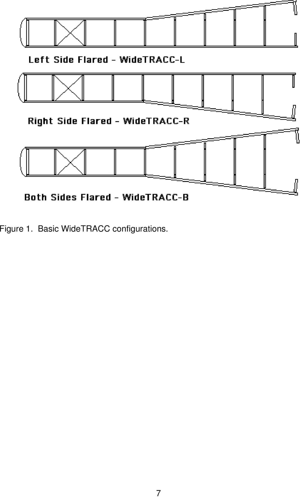
7 Configuration Options The TRACC Family of NCHRP Report 350 qualified crash cushions are available in several configurations as shown in Table 1. Test Level Width Length TRACC 3 24, ShorTRACC 2 24, FasTRACC 3+ * 24, WideTRACC L 3, ** 21 ** WideTRACC R 3, ** 21 ** WideTRACC B 3, 3+ * 58 ** 21 *** Table 1 * - Test Level 3+ refers to the fact that some units have been tested or are accepted for test conditions that exceed normal Test Level 3. Additional testing included a 2000 kg vehicle impacting at zero degrees at 70 MPH. ** - The width of the WideTRACC-L and R can be increased by adding approved wing extensions on one side. The extensions will add 28 inches of length and 3-7/16 inches of width for each section. *** - The width of the WideTRACC-B can be increased by adding approved wing extensions on both sides. The extensions will add 28 inches of length and 6-7/8 inches of width for each section WideTRACC offers designers options in protecting wide barriers and gores. The WideTRACC can be flared down its left side only, its right side only, or both sides simultaneously. Figure 1 shows the basic options available. The extension attached to the rear of the WideTRACC consists of a pair of guardrail panels continuing the height and flare angle of the WideTRACC side panels. The panels are supported by specially designed braced, base-plated posts. The lower panel is further supported by a channel that is installed between the post and the guardrail. 6

8 Figure 1. Basic WideTRACC configurations. 7
9 Unidirectional Application Location Requirements Installation of a TRACC System and its transitions depends on the traffic pattern and the backup structure at the particular location. Unidirectional traffic (one side or both) requires no transition. See Figures 2 and 3. The backup frame can be attached to any solid structure including a square cast-in-place concrete pillar, a vertical concrete wall, or the end of a New Jersey style barrier. The backup frame provides a hole pattern that may require adaptation to the backup structure. Trinity Highway Products can provide an adaptor to allow direct attachment of the backup frame to a variety of concrete barrier profiles. Call Technical Service at with questions regarding this and other types of installation. Figure 2. Unidirectional Traffic Flow - One Side - Requires No Transition. Figure 3. Unidirectional Traffic Flow - Both Sides - Requires No Transition. 8

10 Bidirectional Application For bidirectional installations that face oncoming traffic or reverse direction traffic (see figure 4), the appropriate transition(s) should be installed on the reverse traffic side of the backup structure. Figure 4. Bidirectional Traffic Flow - Requires Transition on One Side. Approach Zone and Clear Zone The TRACC System should not be placed directly behind a raised curb. The approach area in front of the system should slope at a different rate no greater than 10:1 in the direction of traffic flow. The cross slope should differ by no more than 12:1. The clear zone behind the TRACC should be consistent with the area behind the downstream Length-of-Need of the barrier. The entire length of the TRACC can be used in Length-of-Need calculations as it is fully redirecting. Downstream Zone The TRACC should be installed so that a 60 clear space will exist on both sides of the backup structure for the side panels to retract during an end-on impact (see figure 5). Figure 5. Clear Space for Panel Retraction 9

11 Installation Options Foundations During an impact, the stopping force provided by a TRACC System is NOT transferred to the backup structure beyond the cushion. All the stopping loads pass to the foundation BELOW the system through the anchor bolts that attach the system to the foundation. TRACC Systems can be anchored to combinations of asphalt, concrete, and compacted subbase as shown in Table 2 below. 6 Reinforced Concrete 8 Unreinforced Concrete 3 Minimum Asphalt over 3 Minimum Concrete 6 Asphalt over 6 Compact Subbase 8 Minimum Asphalt Table 2. Foundation Options TRACC Foundation Drawings SS1010 SS1011 SS1013 TRACC TL-3 Crash Cushion Attenuating Terminal 22 Concrete Foundation Plan FasTRACC TL-3 Crash Cushion Attenuating Terminal 26 8 Concrete Foundation Plan ShorTRACC TL-2 Crash Cushion Attenuating Terminal 14 Concrete Foundation Plan 10

12 Backup Support and Transition Options The TRACC with its sliding side panels can be attached or transitioned to any backup structure capable of supporting the last frame. If the system has been extended to greater widths as described previously for the WideTRACC, the flared guardrail panels used to create the extra width can be attached to any downstream barrier or structure just as a standard guardrail would be attached. The following drawings are located in the Appendix of this manual. They provide the necessary detail for attachment and transition to their subject structures. SS453, TRACC Transition to W-Beam Median Barrier Soil Post Option SS454, TRACC Transition to Thrie Beam Median Barrier Soil Post Option SS455, TRACC Transition to W-beam Median Barrier Plan, Elevation & Sections SS456, TRACC Transition to Vertical Wall SS461, TRACC Transition to Concrete Safety Shape Barrier Plan, Elevation & Sections SS462, TRACC Transition to Concrete Barrier Single Slope Plan, Elevation & Sections SS463, TRACC Transition to Thrie Beam Median Barrier Plan, Elevation & Sections SS464, TRACC Transition to Thrie Beam Median Barrier All Wood Post SS497, WideTRACC - Optional Wing Extensions Nose Delineation Options The TRACC is intended for use on either shoulder or in the median in both unidirectional and bidirectional traffic situations. To provide the greatest level of safety, the delineation of the plastic nose section can be customized for any particular location. Four pieces of reflective tape are provided with the TRACC and can be used to delineate left shoulder, right shoulder, and gore applications. All four identical pieces of reflective tape can be used to create the three designs as shown below. The plastic nose should be attached to the front of the TRACC system using the side panel attachment hardware already located on the system. Gore Area Right Shoulder Left Shoulder Figure 6. Nose Delineation Options. Note: Consult local transportation authorities for delineation requirements. 11

13 TRACC FAMILY INSTALLATION GUIDELINES Drawings and Bills of Material Drawings and bills of material for the most popular TRACC System options are shown in the Appendix to this manual. If parts are missing from a TRACC System shipment or if you have questions regarding installation options, please contact Trinity Highway Products Technical Service at Recommended Tools and Equipment 1. Forklift or Crane (4000 pound capacity) 2. Lifting Slings or Chains 3. Air hammer/drill 35/50# and appropriate power source 4. Rock drill bit 11/16 x 16 with 30 extender 5. Socket and Ratchet Set or Flat Wrenches - 3/8 to 1-1/4 6. Traffic control equipment 7. Gloves, safety goggles, and back protection for lifting 8. Dispensing Gun and Mixing Tubes for Hilti HY-150 Adhesive 12

14 Safety Instructions Always use appropriate safety precautions when operating power equipment, mixing chemicals, and moving heavy equipment. Gloves, safety goggles and back protection should be used. Safety measures incorporating appropriate traffic control devices should also be used to protect personnel while at the installation site. Trinity Highway Products offers an economical and effective truck mounted attenuator, the MPS-350, for the protection of workers in work zones. For more information on the MPS-350 call , or visit the Trinity Highway Products website at 13

15 Installation of System To facilitate accurate communication regarding the parts of the TRACC and WideTRACC, Figure 7 shows the two systems with side panels removed and major parts labeled. Figure 7. Major Components of the TRACC and WideTRACC. (The side panels have been removed from the outside of the systems for clarity.) Lifting the System TRACC Systems can be lifted as complete units by threading lifting chains or slings directly through the tops of the frames. Someone should maintain control of the system by guiding the end as it is lifted and moved. Care should be taken to ensure that the system can be handled safely prior to moving. 14
 Lifting the System TRACC Systems can be lifted as complete units by threading lifting chains or slings directly through the tops of the frames.")
16 Anchoring the System TRACC Systems can be installed on combinations of asphalt and concrete. Table 3 shows the types of foundations that can be used and the anchoring studs that are required. In general, concrete installation can be performed using 7-1/8 inch anchor studs while asphalt installation requires 18-inch anchor studs. Holes should be drilled 1.5 inches less than the overall length of the anchor stud to ensure proper embedment. TRACC Systems can be placed directly onto the foundation as a complete unit. The system should be aligned within 1 of the downstream barrier according to the approach and downstream zone requirements set forth in the section entitled, Location Requirements. Holes for the anchor studs can be drilled into the foundation using the system as a template. Because of the open design of all the TRACC systems including the WideTRACC, it is not necessary to disassemble any portion of the system in order to drill the anchoring holes. Note that the flared portion of the WideTRACC requires additional outboard anchors that have been shipped loose and must also be anchored to the foundation. Special attention should be paid to drawing SS496, WideTRACC Double Flare - Plan Elevations and Sections, for the location of those outboard anchors. After the holes are drilled, the adhesive system can be dispensed into the hole and then the anchor stud should be suspended by its nut and washer through the crosstie. Figure 8 shows how the anchor stud should pass through the crosstie suspended by its nut and washer. The stud should hang in the uncured adhesive with no threads showing above the nut. Final tightening of the anchor nuts should be done after the adhesive has set. (See adhesive manufacturer s instructions for set times under various environmental conditions.) Table 3. Anchor Stud Selection Table Foundation Anchor Stud Size 6 Reinforced Concrete 5/8 d x 7 1/8 long 8 Unreinforced Concrete 5/8 d x 7 1/8 long 3 Minimum Asphalt over 3 Min. Concrete 5/8 d x 18 long 6 Asphalt over 6 Compact Subbase 5/8 d x 18 long 8 Minimum Asphalt 5/8 d x 18 long NOTE: If asphalt is located over a minimum of 6-inches of concrete, the 18-inch anchor studs can be cut off to a total length equal to the asphalt thickness plus 7.5 inches. 15

17 Figure 8. Suspending the Anchor Studs in the Uncured Adhesive. Attaching Backups and Transitions The last support frame on a TRACC System must be attached to something in order to support the side panels and any required transition panels. While no direct stopping forces are transmitted into the backup support structure, its presence is important for possible redirecting impacts. Drawings in the Appendix show the TRACC systems attached to and shielding a variety of downstream barriers and structures. For more information about specific installation options not shown in the Appendix drawings, contact Technical Service at NOTE: The width of the WideTRACC can be adjusted through the addition of wing extension sections as shown in drawing SS497, WideTRACC Double Flare Wing Extension Structures, located in the Appendix. 16

18 TRACC FAMILY REPAIR AFTER IMPACT Repair Options TRACC systems are designed for field repair or rapid replacement of the entire unit. The energy absorbing portions of the base assembly of the TRACC system can be replaced in stages depending on the extent of the impact. Because TRACC systems are delivered fully assembled, it is extremely practical to replace the entire damaged system on the roadside and then perform the necessary repairs safely and accurately in the maintenance shop away from traffic dangers. Many of a TRACC system s components remain undamaged after most impacts making refurbishment simple and economical. NOTE: TRACC PRODUCTS ARE NOT DISPOSABLE. COMPLETE REPLACEMENT ON THE ROADSIDE AFTER AN IMPACT IS A CONVENIENT - BUT NOT REQUIRED - WAY TO PROTECT WORKERS BY LIMITING EXPOSURE TO TRAFFIC. UP TO 98% OF A TRACC SYSTEM IS REUSABLE AFTER DESIGN IMPACTS REGARDLESS OF WHETHER THE REPAIR IS PERFORMED IN THE FIELD OR IN THE SAFETY OF THE MAINTENANCE YARD. Types of Damage TRACC Systems are designed to withstand end-on impacts and redirecting side impacts. Side impacts, depending on the severity, may only cause cosmetic damage to the system. Any system that has been impacted along its side should 17

19 be examined to make sure that the damage is only cosmetic and that any damage that might hinder subsequent function of the system is repaired. During some severe high-speed redirecting impacts with heavy vehicles, a TRACC System may become permanently twisted. If the deformation of the base causes a portion of one side of the system to be raised more than one and one half inches when compared to the other side of the system, then the damaged portion of the base assembly should be replaced. Field Repair The 2005 TRACC Family of Crash Cushions is specifically designed for rapid field repair. Removal and replacement of the system remains a valid option for those who prefer to work on the system away from the roadside. NOTE: Minor impacts that stroke the system less than 53 inches will require pulling the sled out to its original position and checking the system for damage. If there is no damage then the system is ready for service. If damaged components are found, they should be replaced. TRACC Systems can be repaired in the field by replacing the parts that have been damaged. The first step for repair will be to disconnect the sled and its attached side panels from the remainder of the system and pull them back to their original upstream location. To facilitate this it may be necessary to release the shredder plates from the sled and to partially remove the straps that brace the lower part of the sled. Don t forget to replace the shredder plates and reattach the straps once the sled is relocated to its original position. The energy absorbing rip plates attached to the top of the base assembly can be replaced in stages. The rip plates are held in place with doubler plates. Each doubler plate is secured with three (3) bolts. The doubler bolts are accessed directly from above the base assembly. Special care should be taken to ensure that new rip plates are installed in the proper location on the base assembly. Please refer to the applicable assembly drawing in the appendix for details about rip plate location and attachment. The side panels and frames can now be redistributed along the length of the system. It may be necessary to loosen some of the panel attachment hardware in order to facilitate respacing. The reassembled sled and its side panels can be attached to the remainder of the system and all the hardware tightened to complete the repair job. Several innovative features have been incorporated into the 2005 TRACC system to make this process simple. 18

20 In the case of redirecting impacts along the side of the system, it may be necessary to replace only side panels and other upper structural pieces so long as the base assembly under the system is not damaged. Removal / Replacement of System The TRACC can be removed from its foundation by releasing the anchor nuts that hold the crossties down. Flat wrenches may be required to access the anchor studs under the displaced frames and sled. Once released, the system can be lifted as a unit and transported back to a maintenance facility for repair. A new or reconditioned TRACC can be positioned on the existing anchor studs and firmly attached using the appropriate nuts and washers. In some impacts, a small number of anchor studs may become bent or fractured. In these cases it will be necessary to remove the old anchor, drill out the adhesive in the old hole, and replace the removed anchor with a new anchor and adhesive. Repair at Maintenance Facility In general, the procedure for repairing a TRACC at a Maintenance Facility will be the same as a field repair. Should you encounter technical difficulties, help is available by calling Trinity Highway Products Technical Service at The first step for repair will be to disconnect the sled and its attached side panels from the remainder of the system and pull them back to their original upstream location. To facilitate this it may be necessary to release the shredder plates from the sled and to partially remove the straps that brace the lower part of the sled. Don t forget to replace the shredder plates and reattach the straps once the sled is relocated to its original upstream position. The energy absorbing rip plates attached to the top of the base assembly can be replaced in stages. The rip plates are held in place with doubler plates. Each doubler plate is secured with three (3) bolts. The doubler plate bolts are accessed directly from above the base assembly. Special care should be taken to ensure that new rip plates are installed in the proper location on the base assembly. Please refer to the applicable assembly drawing in the appendix for details about rip plate location and attachment. The side panels and frames can now be redistributed along the length of the system. It may be necessary to loosen some of the panel attachment hardware in order to facilitate respacing. The reassembled sled can be reattached to the side panels and all the hardware tightened to complete the repair job. 19

21 APPENDIX SS453 SS454 SS455 SS456 SS461 SS462 SS463 SS464 SS497 SS1000 SS1001 SS1002 SS1003 SS1004 SS1005 SS1006 SS1007 SS1008 SS1009 SS1010 SS1013 SS1018 SS1019 TRACC Transition to W-Beam Median Barrier Soil Post Option TRACC Transition to Thrie Beam Median Barrier Soil Post Option TRACC Transition to W-beam Median Barrier Plan, Elevation & Sections TRACC Transition to Vertical Wall TRACC Transition to Concrete Safety Shape Barrier Plan, Elevation & Sections TRACC Transition to Concrete Barrier Single Slope Plan, Elevation & Sections TRACC Transition to Thrie Beam Median Barrier Plan, Elevation & Sections TRACC Transition to Thrie Beam Median Barrier All Wood Post WideTRACC - Optional Wing Extensions Crash Cushion Attenuating Terminal - Plan, Elevations, and Sections, Assembled Unit, Base, and Rip Plate Schematic Crash Cushion Attenuating Terminal Assembled Base Unit Crash Cushion Attenuating Terminal - Plan, Elevations, and Sections, Shop Assembly Details, Pages 1, 2 Crash Cushion Attenuating Terminal - Plan, Elevations, and Sections, Unidirectional, Direct Attachment ShorTRACC Crash Cushion Attenuating Terminal Assembled Base Unit ShorTRACC Crash Cushion Attenuating Terminal Shop Assembly Details, Pages 1, 2 ShorTRACC Crash Cushion Attenuating Terminal Plan, Elevation, and Sections, Unidirectional, Direct Attachment FasTRACC Crash Cushion Attenuating Terminal Assembled Base Unit FasTRACC Crash Cushion Attenuating Terminal Plan Elevation, and Section, Shop Assembly Details, Pages 1, 2 FasTRACC Crash Cushion Attenuating Terminal Plan, Elevation, and Sections, Unidirectional, Direct Attachment TRACC Crash Cushion Attenuating Terminal, 22 Concrete Foundation Plan TRACC Crash Cushion Attenuating Terminal, 15 Concrete Foundation Plan 58 WideTRACC Double Flare Crash Cushion Attenuating Terminal Plan, Elevation, and Sections Shop Assembly Details, Pages 1, 2, 3 58 WideTRACC Double Flare Crash Cushion Attenuating Terminal Plan, Elevation, and Sections Unidirectional, Direct Attachment 20
22
23
24
25
26
27
28
29
30
31
32
33
34
35
36
37
38
39
40
41
42
43
44
45
46
47
48
49
50 2525 Stemmons Freeway Dallas, Texas (USA only) (Outside USA)
HEART Product Description Assembly Manual
 HEART Product Description Assembly Manual Part No. 620293B Revised February 25, 2009 2525 2525 Stemmons Stemmons Freeway Freeway Dallas, Dallas, Texas Texas 75207 75207 IMPORTANT: These These instructions
X-Tension TM Guardrail End Terminal
 Installation and Maintenance Manual X-Tension TM Guardrail End Terminal Step by Step Instructions for the Tangent, Flared and Median Applications Barrier Systems Sales and Service 3333 Vaca Valley Pkwy,
SKT-SP Tangent Terminal
 Assembly Instructions for SKT-SP Tangent Terminal & FLEAT-SP Flared Terminal SP Standard Post System Guardrail Terminals ROAD SYSTEMS, INC. P. O. Box 2163 Big Spring, Texas 79721 Phone: (432) 263-2435
62 nd Annual Missouri Traffic and Safety Conference. M.A.S.H.: The New Safety Hardware Crash Testing Criteria
 62 nd Annual Missouri Traffic and Safety Conference M.A.S.H.: The New Safety Hardware Crash Testing Criteria Richard Albin Federal Highway Administration Resource Center Safety and Design Team May, 2011
INSTALLATION MANUAL UNIVERSAL TAU-II. NCHRP 350 TL-3 Redirective, Non-Gating, Crash Cushion
 INSTALLATION MANUAL UNIVERSAL TAU-II NCHRP 350 TL-3 Redirective, Non-Gating, Crash Cushion INTRODUCTION STANDARD LIMITED WARRANTY Lindsay Transportation Solutions, Inc. LTS ( formerly Barrier Systems )
ENERGY ABSORPTION SYSTEMS
 SRT-350 8 POST Guardrail End Treatment Assembly Manual Part No. 620296B Revised June 24, 2008 ENERGY ABSORPTION SYSTEMS SRT-350 8 POST System Guardrail End Treatment Installation, Maintenance, and Repair
REACT 350 II. Product Description Assembly Manual
 REACT 350 II Product Description Assembly Manual Part No. 618083B Revision A July 2013 REACT 350 II Product Description Assembly Manual 2525 Stemmons Freeway Dallas, Texas 75207 Important: These instructions
INFORMATION HANDOUT MATERIALS INFORMATION FOR CONTRACT NO: 05-0L7014 PROJECT ID: 0500020286 ALTERNATIVE CRASH CUSHION SYSTEM
 INFORMATION HANDOUT FOR CONTRACT NO: 05-0L7014 PROJECT ID: 0500020286 MATERIALS INFORMATION ALTERNATIVE CRASH CUSHION SYSTEM LOCATION 22 CROSS SECTIONS ROUTE: 05-SCr-17-6.0/12.6 ADDED PER ADDENDUM No.
Session 3: Guardrail Design and Sitespecific. Considerations
 FHWA Roadway Departure Technology Transfer Roadside Safety Systems Installer Training : Guardrail Design and Sitespecific Installation Considerations 3-1 Course Topics Session 2 Testing Requirements and
Table of Contents (Continued) 13-5.01 Warrants... 13-5(1) 13-5.02 Median Barrier Types... 13-5(1)
 13-5.01 Warrants... 13-5(1) 13-5.02 Median Barrier Types... 13-5(1)") December 2003 ROADSIDE SAFETY 13(i) Chapter Thirteen ROADSIDE SAFETY Table of Contents Section Page 13-1.0 DEFINITIONS... 13-1(1) 13-2.0 CLEAR ZONES... 13-2(1) 13-2.01 Background... 13-2(1) 13-2.02 Application...
December 2003 ROADSIDE SAFETY 13(i) Chapter Thirteen ROADSIDE SAFETY Table of Contents Section Page 13-1.0 DEFINITIONS... 13-1(1) 13-2.0 CLEAR ZONES... 13-2(1) 13-2.01 Background... 13-2(1) 13-2.02 Application...
HIGHWAY PRODUCTS. Revised January 2008 BUILDING TOMORROW S HIGHWAY SAFETY SOLUTIONS TODAY
 TRINITY HIGHWAY PRODUCTS Revised January 008 BUILDING TOMORROW S HIGHWAY SAFETY SOLUTIONS TODAY TABLE OF CONTENTS Crash Cushions 0 Posts Guardrail INNOVATION As an industry leader in the guardrail and
16 April 2012 1032011-F 1994-2002 Dodge Adjustable Track bar with Relocation Bracket 1
 16 April 2012 1032011-F 1994-2002 Dodge Adjustable Track bar with Relocation Bracket 1 BD Adjustable Track Bar w/bracket Dodge 2500-3500 4WD Models 1994-2002 Dodge 1500 4WD Model 1994-2001 P/N# 1032011-F
CHAPTER 14: GUARDRAIL and BARRIERS
 CHAPTER 14: GUARDRAIL and BARRIERS If you have any questions regarding guardrail, end treatments and/or pay items included in your plan, please contact the Project Design Services Unit or the Design Standards
Superseded. The average time for a normal repair after a crash is approximately 1.5 to 2 hours for a 3- person crew.
 To: Subject: Purpose: All HQ Directors: Operations, Planning and Major Projects All Regional Directors All Regional Managers, Engineering All Regional Traffic Engineers All District Managers Transportation
MGB Chrome Bumper Conversion
 MGB Chrome Bumper Conversion Installation Instructions For 1974 1/2-1980 MGB This kit requires cutting, welding, and painting. Professional installation recommended. Note: Every MGB body is slightly different
Owner s Manual Gantry Cranes
 Owner s Manual Gantry Cranes Fixed Height Gantry Crane MODEL NUMBER: SERIAL NUMBER: CAPACITY IN TONS: Telescoping Gantry Crane Bushman AvonTec 262-790-4200, 800338-7810, Fax 262-790-4200 www.bushmanavontec.com
Safe & Sound Bridge Terminology
 Safe & Sound Bridge Terminology Abutment A retaining wall supporting the ends of a bridge, and, in general, retaining or supporting the approach embankment. Approach The part of the bridge that carries
11 Guardrail. W-Beam Guardrail Pre-Installation Inspection During Installation Basis for Use. Modified Guardrail. End Treatments and Transitions
 11 Guardrail W-Beam Guardrail Pre-Installation Inspection During Installation Basis for Use Modified Guardrail End Treatments and Transitions Footings and Anchors Impact Attenuators Measurement and Payment
TITAN Fuel Tanks. INSTALLATION INSTRUCTIONS G e n e r a t i o n V
 TITAN pt. no.: 02 0000 0143 Important: Please read these instructions carefully and completely before starting the installation. TITAN Fuel Tanks INSTALLATION INSTRUCTIONS G e n e r a t i o n V Extended
STEADYfast Stabilizer Installation Notes Fifth Wheel and Travel Trailers 11/23/13
 STEADYfast Stabilizer Installation Notes Fifth Wheel and Travel Trailers 11/23/13 (See Supplemental Instructions for trailers with heavy duty round footplates and/or Power Leveling Systems) PHONE SUPPORT
Important: Please read these instructions carefully and completely before starting the installation. TITAN Fuel Tanks
 TITAN pt. no.: 03 0000 0120 Important: Please read these instructions carefully and completely before starting the installation. TITAN Fuel Tanks INSTALLATION INSTRUCTIONS G e n e r a t i o n V Extended
8' W x 8' H or 10' H Peak Style Shelter Assembly Instructions
 ' W x ' H or ' H Peak Style Shelter Assembly Instructions Description ' x ' x ' Peak Style Shelter - Gray ' x ' x ' Peak Style Shelter - Gray Recommended Tools Please read instructions COMPLETELY before
EMPLOYEE FALL PROTECTION
 EMPLOYEE FALL PROTECTION You can fall from any height and be seriously injured or killed. In the construction industry, as well as any other industry, when falls from heights happen, they are usually very
GEK-90214B. GE Lift Truck. User s Guide 144D2933G1 144D2912G1 144D2911G5
 g GEK-90214B GE Lift Truck User s Guide 144D2933G1 144D2912G1 144D2911G5 GE LIFT TRUCK EACH USER HAS THE RESPONSIBILITY TO INSTRUCT ALL PERSONNEL ASSOCIATED WITH THIS EQUIPMENT ON ALL SAFETY PRECAUTIONS
VI. VEHICLE IMPACT WITH CURB-AND-GUARDRAIL SYSTEMS. high-speed roadways, they are often required because of restricted right-of-way, drainage
 VI. VEHICLE IMPACT WITH CURB-AND-GUARDRAIL SYSTEMS 6.1 Introduction It is often necessary to use a curb at a particular location that also warrants a traffic barrier. Inadequate design of these curb-and-barrier
Elo Touch Solutions Wall-mounting Kit for the 5501L IDS Touchmonitors
 Installation Manual Elo Touch Solutions Wall-mounting Kit for the 5501L IDS Touchmonitors SW602206 Rev B Table of Contents Chapter 1: Safety Warning... 3 Chapter 2: Kit Contents... 4 Included in Kit...
Capital Costs for Roadside/Median Barrier Systems
 Capital Costs for Roadside/Median Barrier Systems The following basic costs for different roadside barrier systems were developed for use with Alberta Infrastructure and Transportation s new Roadside Design
WILDING WALLBEDS BUNK BED INSTALLATION INSTRUCTIONS
 WILDING WALLBEDS BUNK BED INSTALLATION INSTRUCTIONS Instruction Booklet 18 WARNING! ALL MURPHY/WALLBED SYSTEMS CONTAIN POWERFUL LIFTING COMPONENTS. FAILURE TO USE AND FOLLOW THESE INSTRUCTIONS DURING THE
Report on. Wind Resistance of Signs supported by. Glass Fiber Reinforced Concrete (GFRC) Pillars
 Pillars") Report on Wind Resistance of Signs supported by Glass Fiber Reinforced Concrete (GFRC) Pillars Prepared for US Sign and Fabrication Corporation January, 2006 SUMMARY This study found the attachment of
Report on Wind Resistance of Signs supported by Glass Fiber Reinforced Concrete (GFRC) Pillars Prepared for US Sign and Fabrication Corporation January, 2006 SUMMARY This study found the attachment of
INSTRUCTIONS: LocknCharge Laptop Carts
 INSTRUCTIONS: LocknCharge Laptop Carts www.lockncharge.com Extra Tools required: Hammer, Philips head screwdriver, medium adjustable spanner. (Allen key supplied) (Panel colours for illustration purposes
Structural Holding System
 Structural Holding System Users Manual November 2013 by Vehicle Service Group. All rights reserved. CO8812.1 502071 Rev. - 11/21/2013 CHIEF'S LIMITED ONE-YEAR WARRANTY & LIABILITY Chief Automotive Technologies
http://waterheatertimer.org/troubleshoot-rheem-tankless-water-heater.html
 http://waterheatertimer.org/troubleshoot-rheem-tankless-water-heater.html TECHNICAL SERVICE DEPARTMENT Removal, Cleaning, & Reinstallation of the Burner Assembly For models 74 & GT199 Required tools -
SLACK PERFORMANCE KARTS
 SLACK PERFORMANCE KARTS SET UP GUIDE Thank you for purchasing a 2013 Slack Axiom Chassis. Performance Mfg. strives to provide you with the very best chassis and components on the market today. Your satisfaction
Assembly Instructions for the InteliTrack 3000 Rail Tracking System
 Assembly Instructions for the InteliTrack 3000 Rail Tracking System InteliTrack is a trademark of Sedona Solar Technology. Sedona Solar Technology 16 April 2013 1 1. Before you begin WARNING Safety equipment
LG G5 Chassis Brace Gen 5 Camaro THE MOST POWERFUL HEADERS ON THE PLANET Brought to you by LG Motorsports 972-429-1963
 LG G5 Chassis Brace Gen 5 Camaro THE MOST POWERFUL HEADERS ON THE PLANET Brought to you by LG Motorsports 972-429-1963 Thank you for purchasing LG Motorsports products for your Gen 5 Camaro. Parts Inventory:
Chapter 10 - Scaffolding Systems
 Chapter 10 - Scaffolding Systems Contents Chapter 10 - Scaffolding Systems... 10-1 Check and Oil the Pump Jacks... 10-4 Set Pump Jack Brackets... Error! Bookmark not defined. Set Pump Jack Poles... 10-5
RZ Guardrail System Installation Manual
 TM RZ Guardrail System Installation Manual RZ Guardrail System Compliance is based on OSHA standards: (Standards - 29 CFR) 1910.23 (e) and (Standards - 29 CFR) 1926.502 (b) Failure to read, understand
TracRac G2. Overhead Rack Installation Instructions. TracRac Inc. 994 Jefferson St. FallRiver MA 02721 www.tracrac.com 800-501-1587 IN-42000_B
 IN-42000_B TracRac G2 Overhead Rack Installation Instructions TracRac Inc. 994 Jefferson St. FallRiver MA 02721 www.tracrac.com 800-501-1587 Thank you for your purchase of a TracRac G2 Sliding Cargo Manaagement
FRONT BUMPER INSTALLATION INSTRUCTIONS 2007-2011 DODGE / MERCEDES SPRINTER
 Aluminess Products Inc 9402 Wheatlands Ct. #A Santee, CA 92071 619-449-9930 FRONT BUMPER INSTALLATION INSTRUCTIONS 2007-2011 DODGE / MERCEDES SPRINTER Please read before beginning Stainless steel hardware
INSTRUCTIONS THOROUGHLY BEFORE BEGINNING***************
 Bill of Materials: RAC0012 Green Wing Aerodynamic Skirt Kit Item Part Number Description Quantity 1 RMC0218 Gen 2 Trailer Skirt Roadside 1 2 RMC0219 Gen 2 Trailer Skirt Curbside 1 3 RMC0041 Trailer Skirt
New method, replacement of window and window lift, front door
 SERVICE INFORMATION Number: 831-1646 Year: 1996 Month: Market: FEBRUARI ALL New method, replacement of window and window lift, front door Cars concerned All Saab 900 M94- Background A new method of removing
Heavy Glass Frameless Shower Door With Return Panel
 202 Anderson Ave., elvue, KS 66407 Phone: 800-669-9867 Fax: 800-393-6699 www.onyxcollection.com Heavy Glass Frameless Shower Door With Return Panel Full Showers with Return ench Seat with Return FRLSDRPL-0116
Installation Manual. SKU# 21000 series (Base Rails) SKU# 22000 series (Overhead Racks)
 SKU# 22000 series (Overhead Racks)") Installation Manual SKU# 21000 series (Base Rails) SKU# 22000 series (Overhead Racks) Welcome to the world of TracRac! We re delighted that you have chosen TracRac, the ultimate sliding truck rack system.
Installation Manual SKU# 21000 series (Base Rails) SKU# 22000 series (Overhead Racks) Welcome to the world of TracRac! We re delighted that you have chosen TracRac, the ultimate sliding truck rack system.
INSTALLATION INSTRUCTIONS. 6111 Air Spring Kit 2011+ Ford F250/F-350 Single Wheel 2WD 2011+ Ford F350 Dually 2WD IMPORTANT NOTES
 INSTALLATION INSTRUCTIONS 6111 Air Spring Kit 2011+ Ford F250/F-350 Single Wheel 2WD 2011+ Ford F350 Dually 2WD Thank you for purchasing a quality Hellwig Product. PLEASE READ THIS INSTRUCTION SHEET COMPLETELY
GUARDRAIL INNOVATION FLOWS FROM HERE
 INNOVATION FLOWS FROM HERE ENSURING SAFETY ON CANADIAN HIGHWAYS The economics, versatility, and performance of Guardrail surpass all other roadside barrier systems. Guardrail provides highly-visible protection
Mark Cramer Inspection Services, Inc.
 Mark Cramer Inspection Services, Inc. 492 Twentieth Avenue, Indian Rocks Beach, FL 34635-2970 (727) 595-4211 Fax (727) 596-7583 Certified Member #12085 American Society of Home Inspectors Construction
Guidelines for Earthquake Bracing of Residential Water Heaters
 Guidelines for Earthquake Bracing of Residential Water Heaters Department of General Services Division of the State Architect 1102 Q Street, Suite 5100 Sacramento, CA 95814 Phone: (916) 324-7099 Fax: (916)
WARNING! DO NOT ATTEMPT TO INSTALL THIS KIT IN A POWERED CONVEYOR.
 Model: Document Number: 64058111 Kit Number: 64058112 Revision: 02 Description: Release Date: 04/08 Introduction This kit allows a PS90 scale to be integrated into a standard gravity conveyor. The kit
TONNEAU INSTALLATION GUIDE
 TONNEAU INSTALLATION GUIDE Warranty, Care & Maintenance Model 4056 Toyota Tacoma Double Cab 5' Short Bed 2005-Current (With Multi-Track System) EASY AS 1-2-3! NORMAL INSTALLATION TIME 30 MINUTES For Warranty
TABLE OF CONTENTS. I. TROUBLESHOOTING... 2 - Section 1.01: Common Problems/Solutions... 2
 BAL Accu-Slide System I. Table of Contents TABLE OF CONTENTS I. TROUBLESHOOTING... 2 - Section 1.01: Common Problems/Solutions... 2 II. GETTING STARTED... 5 - Section 2.01: Tools You Will Need... 5 - Section
42U/45U 28" Wide Rack Installation & Service Guide
 42U/45U 28" Wide Rack Installation & Service Guide 96-00171-005 Rev B Important Information Information in this document is subject to change without notice and does not represent a commitment on the part
Materials. Estimating Steel. Players. Materials. Shop Drawings. Detailing Process. Standard shapes. Fabricated members, Built-up sections
 Materials Standard shapes W sections, C channels, Structural T, Angles, Pipes, Tubes, Rods and Plates Fabricated members, Built-up sections Adding plates to beam flanges, Stiffeners to beam webs Built
BUILDINGA 1/10 SCALE FLATBED TRAILER
 VOLUME 1, ISSUE 1 BUILDINGA 1/10 SCALE FLATBED TRAILER BUILT, DESIGNED & WRITTEN BY NATHAN MYERS MATERIALS: FEATURES: While the design was kept simple to allow anyone to be able to build their own trailer,
2.9 WINDOW & DOOR BUCKS
 2.9 WINDOW & DOOR BUCKS Bucks provide attachment surfaces for windows and doors while holding back concrete from these openings during concrete placement. Mark the center and edges of openings as you place
1958-64 WINDOW CHANNEL, WEATHERSTRIP & WHISKER STRIP REPLACEMENT FOR 2-DOOR SEDANS
 By Denny Williams Photos by Denny Williams 1958-64 WINDOW CHANNEL, WEATHERSTRIP & WHISKER STRIP REPLACEMENT FOR 2-DOOR SEDANS Denny Williams - Technical Writer Denny is first and foremost a dyed-in-thewool
DIVISION: 04 00 00 MASONRY SECTION: 04 05 19.16 MASONRY ANCHORS REPORT HOLDER: HILTI, INC. 7250 DALLAS PARKWAY, SUITE 1000 PLANO, TEXAS 75024
 0 ICC-ES Report ICC-ES (800) 423-6587 (562) 699-0543 www.icc-es.org 000 Most Widely Accepted and Trusted ESR-3342 Reissued 08/2015 This report is subject to renewal 08/2017. DIVISION: 04 00 00 MASONRY
Policy on Water Heater Installations Policy No. UPC 510-1-94 Effective: September 1, 1995 Revised: February 10, 1996
 CITY OF SAN JOSE BUILDING DIVISION POLICY Policy on Water Heater Installations Policy No. UPC 510-1-94 Effective: September 1, 1995 Revised: February 10, 1996 All new and replacement water heaters installed
The Drink-Aide The NEW look of independence
 The Drink-Aide The NEW look of independence Introducing Drink-Aide What is Drink-Aide? The Drink-Aide is a water bottle that attaches easily to a wheelchair for use by persons with little or no upper
2100 AD 015 0009 Mirror Elevator Ball Nut Replacement Procedure
 2100 AD 015 0009 Mirror Elevator Ball Nut Replacement Procedure Derek Guenther 1/28/2015 Rev. Purpose The purpose of this document is to describe the procedure necessary to replace one of the ball nuts
Walking and Working Surface Checklist:
 Walking and Working Surfaces Purpose: This information is presented to improve the level of safety in our operations, and to inform you that we will comply with the OSHA Standard 29 CFR 1910.23. Responsibility:
MODEL# SLA001-3 "SLIDE & LOCK" A-FRAME POOL LADDER
 MODEL# SLA001-3 "SLIDE & LOCK" A-FRAME POOL LADDER IMPORTANT INSTRUCTIONS: : Read all instructions carefully & completely to become familiar with parts, assembly, safety and proper use of this product.
Best/Flex Gravity Expandable Conveyor Operation, Maintenance and Parts Manual
 Best/Flex Gravity Expandable Conveyor Operation, Maintenance and Parts Manual B/F200 & B/F300 SERIES LongReach Telescopic Conveyors Pty Ltd 6 Capelli Road Wingfield SA 5013 Tel: +61 (8) 8349 4777 Fax:
HIGH TENSION CABLE BARRIER
 Special Provision September 11, 2006 SECTION 02845 S HIGH TENSION CABLE BARRIER PART 1 GENERAL 1.1 SECTION INCLUDES A. Cable barrier materials and installation procedures. 1.2 RELATED SECTIONS A. Section
BUILD A TABLETOP LOOM
 BUILD A TABLETOP LOOM From 1" x 2" stock (actual 3/4" x 1"1/2) cut: 4 pieces 15" long 4 pieces 5"1/2 long Use the above to make 2 frames for the front and back of the loom. From 1" x 4" stock (actual 3/4"
Installation Instructions GOOSENECK MOUNTING KIT Chevrolet/GMC 1500/2500/3500 All except 4-door Crew-Cab
 GOOSENECK MOUNTING KIT Equipment Required: Fastener Kit: F Wrenches: 3/4, 7/8, 15/16 Drill Bits: 1/4 Other Tools: Drill WARNING: Under no circumstances do we recommend exceeding the towing vehicle manufacturers
Guidelines for Earthquake Bracing Residential Water Heaters
 Guidelines for Earthquake Bracing Residential Water Heaters Department of General Services Division of the State Architect In accordance with the Health and Safety Code Section 19215, the Division of the
Set-Up Instructions. (Liner-Based System) UL LISTED. Important Read set-up instructions before assembly. Report any shortages within 72 hours
 UL LISTED. Important Read set-up instructions before assembly. Report any shortages within 72 hours") INDUSTRIAL POWER Set-Up Instructions (Liner-Based System) UL LISTED Important Read set-up instructions before assembly. Report any shortages within 72 hours Specializing in Environmental and Fire-Life
INDUSTRIAL POWER Set-Up Instructions (Liner-Based System) UL LISTED Important Read set-up instructions before assembly. Report any shortages within 72 hours Specializing in Environmental and Fire-Life
Features. Armco Guardrail. Type D1 reflector. Type V reflector. Guardrail on posts
 Armco Guardrail Features Armco Guardrail has gained international acceptance because it: Marks the limit of safe travel and warns of danger Reduces centreline crowding by increasing driver confidence Restrains
STANDARD OPEN PATIO COVER
 STANDARD OPEN PATIO COVER BUILDING & SAFETY DIVISION 201 E. LA HABRA BLVD. LA HABRA, CA 90631 62-90-9710 Call Before You Dig 1-800-227-2600 PLEASE NOTE: This information Bulletin is made available to assist
Executive Summary. In December of 2001, the Region of Durham retained Synectics Transportation Consultants Inc. (Synectics) to prepare a report to:
 to prepare a report to:") Guide Rail, End Treatment and Energy Attenuator Selection Guidelines Page 1 Executive Summary About one-third of all fatal crashes in North America each year involve a single vehicle. For crashes in rural
Guide Rail, End Treatment and Energy Attenuator Selection Guidelines Page 1 Executive Summary About one-third of all fatal crashes in North America each year involve a single vehicle. For crashes in rural
C O N V E Y O R C O M P O N E N T S C H A I N S B E L T S B E A R I N G S
 C O N V E Y O R C O M P O N E N T S C H A I N S B E L T S B E A R I N G S January 2009 Issue 6 Valu Guide Brackets The Ultimate in Adjustability and Cost Savings Valu Guide brackets are part of a family
6 RETROFITTING POST & PIER HOUSES
 Retrofitting Post & Pier Houses 71 6 RETROFITTING POST & PIER HOUSES by James E. Russell, P.E. 72 Retrofitting Post & Pier Houses Retrofitting Post & Pier Houses 73 RETROFITTING POST AND PIER HOUSES This
Elevating Your House. Introduction CHAPTER 5
 CHAPTER 5 Elevating Your House Introduction One of the most common retrofitting methods is elevating a house to a required or desired Flood Protection Elevation (FPE). When a house is properly elevated,
PATHWAY Classic Series with Handrails Portable Wheelchair Ramp INSTRUCTIONS FOR USE 6428 REV A 05-21-09
 PATHWAY Classic Series with Handrails Portable Wheelchair Ramp INSTRUCTIONS FOR USE. INSTRUCTIONS 1) FOR EZ-ACCESS PATHWAY RAMP WITH HANDRAILS 850 pound weight capacity. Available in 4, 6, 8 & 10 lengths.
Training Zone: Instruction Manual
 Training Zone: Instruction Manual More questions? Our Customer Service team is available to answer your questions Monday - Friday from 9:00 M to 5:00 PM PT. E-mail customerservice@trxtraining.com Call
POLE MOUNT SYSTEM EX-3 INSTALLATION
 May 2014 POLE MOUNT SYSTEM EX-3 INSTALLATION The Pole Mount System EX-3 is an easy to install and flexible system designed to allow ONE SYSTEMS loudspeaker systems to be mounted to pole structures. The
Protecting Your Home From Hurricane Wind Damage
 T H E W I N D Protecting Your Home From Hurricane Wind Damage During a hurricane, homes may be damaged or destroyed by high winds and high waves. Debris can break windows and doors, allowing high winds
Express5800/120Ed. Rack Mount Kit Installation Procedures PN: 455-01607-001
 Express5800/120Ed Rack Mount Kit Installation Procedures PN: 455-01607-001 Proprietary Notice and Liability Disclaimer The information disclosed in this document, including all designs and related materials,
Chapter 3 Pre-Installation, Foundations and Piers
 Chapter 3 Pre-Installation, Foundations and Piers 3-1 Pre-Installation Establishes the minimum requirements for the siting, design, materials, access, and installation of manufactured dwellings, accessory
AMF112 Instruction Manual
 AMF112 Instruction Manual Scan here to view product demo and install videos or visit san.us/103 Milestone AV Technologies 6436 City West Parkway Eden Prairie, MN 55344 USA Customer Service Americas: 800-359-5520
ATS Overhead Table Shelf System INSTRUCTION MANUAL
 ATS Overhead Table Shelf System INSTRUCTION MANUAL ATS Overhead Table Shelf System Instruction Manual Warranty Newport Corporation warrants this product to be free of defects in material and workmanship
In-Ground Basketball System Owners Manual
 In-Ground Basketball System Owners Manual Customer Service Center N53 W4700 South Corporate Circle Sussex, WI 53089 U.S.A. Write Model Number From Box Here: WARNING! 3 Capable Adults REQUIRED TOOLS AND
M113 VEHICLE FAMILY RUBBER TRACK INSTALLATION INSTRUCTIONS SOUCY TRACK SYSTEM 04-M113-1ENS (SPLIT IDLER) Litho d in Canada 1 04-M113-1ENS
 Litho d in Canada 1 04-M113-1ENS") M113 VEHICLE FAMILY RUBBER TRACK INSTALLATION INSTRUCTIONS (SPLIT IDLER) 1 # TABLE OF CONTENTS List of parts and tools................................................3 Installation of complete kit...................................................5
M113 VEHICLE FAMILY RUBBER TRACK INSTALLATION INSTRUCTIONS (SPLIT IDLER) 1 # TABLE OF CONTENTS List of parts and tools................................................3 Installation of complete kit...................................................5
Ceiling Mounted Folding Attic Ladders Installation Instructions
 Ceiling Mounted Folding Attic Ladders Installation Instructions WARNING Before you start installing your new Louisville Ceiling Mounted Folding Attic Ladder, you must read and understand the following:
INSTALLATION AND OPERATING INSTRUCTIONS For Model GL1 Gate Locks
 Securitron Magnalock Corp. www.securitron.com ASSA ABLOY, the global leader Tel 800.624.5625 techsupport@securitron.com in door opening solutions INSTALLATION AND OPERATING INSTRUCTIONS For Model GL1 Gate
Seismic Installation for Attic Storage System
 Your Performance Partner Seismic Installation for Storage System CONTENTS SSafety Precautions................................. 2 Required Tools..................................... 2 Parts and Fastener
I BEAM TRACK INSTALLATION
 PDQ 0/700 FESTOON SYSTEM INSTALLATION AND MAINTENANCE INSTRUCTIONS INTRODUCTION The PDQ Festoon System was designed to run on one of three sizes of I-beams: S x., S8 x 8. and S x.. System trolleys must
BMP-7. A sediment filter or an excavated impounding area around a storm drain drop inlet or curb inlet.
 BMP-7 BMP: STORM DRAIN INLET PROTECTION Definition A sediment filter or an excavated impounding area around a storm drain drop inlet or curb inlet. To prevent sediment from entering storm drainage systems
Installation. Smart-UPS VT and MGE Galaxy 3500. Maintenance Bypass Panel with Power Distribution (wall-mount) 10-30 kva 208 V
 10-30 kva 208 V") Installation Smart-UPS VT and MGE Galaxy 3500 Maintenance Bypass Panel with Power Distribution (wall-mount) 10-30 kva 208 V Contents Safety... 1 SAVE THESE INSTRUCTIONS...............................
Installation Smart-UPS VT and MGE Galaxy 3500 Maintenance Bypass Panel with Power Distribution (wall-mount) 10-30 kva 208 V Contents Safety... 1 SAVE THESE INSTRUCTIONS...............................
POLE MOUNT SYSTEM-3 INSTALLATION
 1 May 2014 POLE MOUNT SYSTEM-3 INSTALLATION The Pole Mount System-3 is an easy to install and flexible system designed to allow ONE SYSTEMS loudspeaker products to be mounted to pole structures. The only
INSTALLATION INSTRUCTIONS MULTI-MOUNT KIT Part Number: 75330 Application: Warn HP PowerPlant P/N 71800
 INSTALLATION INSTRUCTIONS MULTI-MOUNT KIT Part Number: 75330 Application: Warn HP PowerPlant P/N 71800 Your safety, and the safety of others, is very important. To help you make informed decisions about
Summary of ET Plus Guardrail End Treatment Inspections
 Summary of ET Plus Guardrail End Treatment Inspections 12/16/2015 Maine Department of Transportation Prepared by Brian Burne, Atlee Mousseau, Clark Sulloway, Doug Gayne, Ulrich Amoussou Guenou & Dale Peabody
Pole Lathe and Shave Horse Design
 Pole Lathe and Shave Horse Design These pictures and accompanying words are Copyright Michael Hughes February 2002. They are not to be re-produced, in part or whole, without permission from the author.
WHI 90-Minute Rated Veneered Door Frame Installation Instructions
 No. 940-03-10 INSTALLATION INSTRUCTIONS 90 MINUTE RATED VENEERED DOOR FRAME DOOR REQUIREMENTS: Consult the door manufacturer to make sure that the doors are qualified for the hardware to be installed,
Roll-Up Door Maintenance Guide
 R Roll-Up Door Maintenance Guide Cable Replacement on Two Spring Type Balancer Page 1 Panel Replacement - Removable Roller Cover Type Bottom Panel Page 1 Panel Replacement - Removable Roller Cover Type
Navico-Northstar 2kW JRC Radar Package, Scanner Cable Removal and Replacement
 Navico-Northstar 2kW JRC Radar Package, Scanner Cable Removal and Replacement This work instruction describes the methods and means for which to remove and reinstall optional scanner cable configurations
Washington State Cable Median Barrier In-Service Study
 Washington State Cable Median Barrier In-Service Study Doug McClanahan Washington State Department of Transportation PO Box 47329 Olympia Washington 98504-7329 Tel: (360) 705-7264 Fax: (360) 705-7330 mcclando@wsdot.wa.gov
DETACHABLE WINDSHIELD AND DOCKING HARDWARE KIT
 -J00 REV. 00-- DETACHABLE WINDSHIELD AND DOCKING HARDWARE KIT GENERAL Kit Number -A, 0-, -, 0-, -, - 0, -0 Models These kits fit and later FXST, FXSTB, FXSTC, and and later FXDWG Harley-Davidson model
Fall Protection System: A system put in place to protect workers from falling. (i.e. installation of guardrails, fall arrest, fall restraint, etc.
 SWP (6) FALL PROTECTION PROGRAM The following information on Fall Protection has been based around the BC OHS Regulations, standards, policies and guidelines. Prior to starting work outside of BC, the
Sliding Barn Door Hardware Installation Instructions BALDUR and ODEN
 Sliding Barn Door Hardware Installation Instructions BALDUR and ODEN Installation Instructions Structural Information For standard systems and most custom single door opening systems. General Overview