DS2149DK/DS21349DK T1/J1 Line Interface Unit Design Kit
|
|
|
- Luke Flynn
- 10 years ago
- Views:
Transcription
1 GENERAL DESCRIPTION The DS2149DK/DS21349DK is a fully integrated design kit for the DS2149 and the DS21349 T1/J1 line interface units (LIUs). It contains the necessary circuitry to evaluate the device in all operation modes, including running the device in hardware and software mode. DESIGN KIT CONTENTS DS2149DK/DS21349DK Board DS Pin PLCC DS Pin PLCC DS2149DK/DS21349DK T1/J1 Line Interface Unit Design Kit FEATURES PLCC 28-Pin Socket for Multiple Part Evaluation Bantam and RJ48 Connectors, Transformers, and Termination Passives for LIU Two Separate and Controllable Transmit Paths for TTIP and TRING for Evaluating Multiple Transformers Equipment-Side Connector for External Data Source/Sink or External Remote Loopback On-Board T1 Crystal Oscillator On-Board 8051 Microprocessor for Software Mode Access Connector Accesses to CS, SCLK, SDI, and SDO for Firmware Development Controllable 5V and 3.3V for VCC and IO Pins to Support the DS2149 and DS21349 LIUs ORDERING INFORMATION PART DS2149DK/ DS21349DK DESCRIPTION T1/J1 Line Interface Unit Design Kit 1 of 14 REV:

2 DS2149DK/DS21349DK T1/J1 Line Interface Unit Design Kit COMPONENT LIST DESIGNATION QTY DESCRIPTION SUPPLIER PART C F capacitor (SMT80123) Digi-Key C3, C6, C9, C12, C15 C17, C F capacitors (SMT80123) Digi-Key C4, C7, C10, C F capacitors (SMT80123) Digi-Key C5, C8, C11, C22, C F capacitors (SMT80123) Digi-Key C13, C F capacitors (SMT127240) Digi-Key C18, C pF capacitors (SMT80123) Digi-Key DS1 DS3, DS5 4 Red LED Digi-Key LN1251C DS mil SO, DS87C520-ECL Dallas Semiconductor DS87C520-ECL J1 1 Connector, RJ48, 8-pin Digi-Key J2, J3 2 Bantam connectors Digi-Key RTT34B02 J4 J11 8 COTO9802 Coto Technology COTO9802 J mil, 16-pin vertical connector Digi-Key JP1 1 Pushbutton switch Digi-Key EVQPAE04M JP2 JP mil SIP jumper 2 position Digi-Key JP7 JP mil SIP jumper 3 position Digi-Key PWR_CONNBAN2 1 Banana connector, 2-pin, red Mouser Electronics PWR_CONNBAN1 1 Banana connector, 2-pin, black Mouser Electronics R1 R3, R12, R resistors (SMT80123) Digi-Key R4, R resistors (SMT80123) Digi-Key R6, R7, R10, R resistors (SMT80123) Digi-Key R8, R resistors (SMT80123) Digi-Key R13, R15, R k resistors SMT80123) Digi-Key R17 R resistors (SMT80123) Digi-Key RN1, RN2 2 1k 10-pin resistor network Digi-Key S1 1 9-pin DB9P connector Digi-Key SW position switch Digi-Key SW2 1 6-pin DPDT switch Digi-Key SSA22 T1 1 1:3 T1 transformer Pulse Engineering PE T2 1 1:2 T1 transformer Pulse Engineering PE T3 1 1:1 T1 transformer Pulse Engineering PE U1 1 PLCCSMT28T0T socket Pioneer Electronics PLCCSMT28T0T U2, U5, U mil SO, 74HC04, hex inverter Digi-Key TC74HC04AFN U3, U4, U mil SO, 74HC03, open collector NAND gate Digi-Key SN74LS38D U8 1 Darlington array Texas Instruments ULQ2003ADR U mil SO, DS232AR Dallas Semiconductor DS232AR U V regulator Maxim MAX8887EZK33 X1 1 EC1-S M XTAL low pro Digi-Key EC1-S M Y MHz crystal oscillator Digi-Key NTH039A of 14

3 BOARD FLOORPLAN DS2149DK/DS21349DK T1/J1 Line Interface Unit Design Kit Figure 1 shows the board layout for the DS2149DK. The DS2149 PLCC socket is in the center of the board. The line-side bantam connectors for the Tx and Rx differential pairs and transformers are at the bottom of the board, while the system connector and configuration jumpers are at the top. The LEDs for INT, INLOOP, and RCL/QPD are in the center of the board, right above the DS2149 socket. The power-supply connectors and power indicator LED are in the upper left corner of the board, while the DB9 serial connector is the upper left. A T1 oscillator sits to the left of the DS2149 socket below a switch for changing the voltage to the DS2149 socket from 5V to 3.3V. Please refer to the general locations on the board when this document references specific items on the DS2149DK. Figure 1. Board Floorplan POWER JACKS GND VDD PWR LED SYSTEM CONNECTOR LEDs NLOOP RCL INT SERIAL PORT Dallas Semiconductor DS2149DK/ DS21349DK OSCILLATOR T1 DS2149 CONFIGURATION JUMPERS TRANSFORMERS Tx Tx Rx LINE CONNECTORS CONFIGURATION SWITCHES Tx Rx 3 of 14

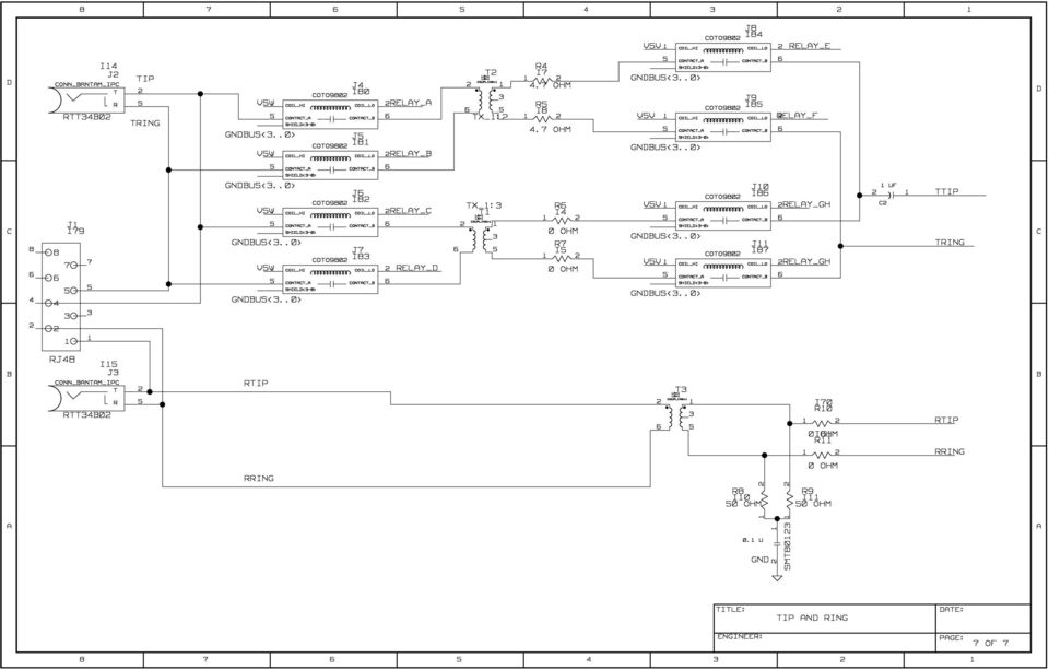
4 LINE-SIDE CONNECTIONS DS2149DK/DS21349DK T1/J1 Line Interface Unit Design Kit The DS2149DK/DS21349DK implements the Tx and Rx line interface networks recommended in the DS2149 and DS21349 data sheets and as shown in Figure 2. To connect the DS2149DK/DS21349DK to T1 or J1 test equipment, connect the equipment to the RJ48 connector or to the two bantam connectors, J2 and J3. Please notice the relays disconnecting TTIP and TRING on T1 and T2. These relays disconnect the series resistors R4 and R5, which is recommended for some long-haul configurations. Pin 16 on the system connector serves as the control line for the relays. When pin 16 is high, T2 is enabled with TTIP and TRING. When it is held low, T1 is enabled with TTIP and TRING. Figure 2. Line-Side Circuitry J2 TRANSMIT T1 C2 1 F TTIP TRING T2 R4 4.7 (1%) Dallas Semiconductor DS2149/DS21349 J3 RECEIVE T3 R5 4.7 (1%) R9 50 (1%) RTIP RRING R8 50 (1%) 4 of 14

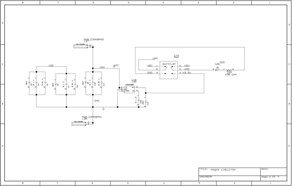
5 SYSTEM CONNECTOR DS2149DK/DS21349DK T1/J1 Line Interface Unit Design Kit A 16-pin system connector at the top of the board gives access to the following signals: RPOS, TPOS, RNEG, TNEG, RCLK_CON, TCLK, MCLK, VDD, GND, CS, SCLK, SDI, and RELAY_CONTROL. By using jumpers to connect TCLK to RCLK_CON, TPOS to RPOS, and TNEG to RNEG, the system connector can also be used to implement an external remote loopback. Additionally, the system connector can read and write to the device without going through the on-board microcontroller. With this feature, you can quickly use this design kit as a working prototype and begin writing firmware for your system. Figure 3 shows a representation of the system connector. Figure 3. System Connector RPOS TPOS RNEG TNEG RCLK TCLK MCLK VDD CS SCLK SDI SDO GND GND GND RELAY_CONTROL POWER-SUPPLY CONNECTORS Connect a 5.0V power supply across the red (VDD) and black (GND) banana jacks. The red PWR LED indicates power is applied to the board. Select the appropriate voltage that needs to be applied to VDD from the power switch below the PWR LED, depending if you are using a DS2149 (5V) or DS21349 (3.3V). MICROCONTROLER AND SERIAL CONNECTOR The DS2149DK/DS21349DK contains an on-board 8051 microcontroller with factory-installed firmware loaded into the microcontroller s EPROM. This firmware translates memory access requests from the RS-232 serial port into register access to the DS2149 or DS21349 in software mode. DemoView, a software application created by Dallas Semiconductor, allows easy read-write access for this device. INSTALLING AND RUNNING THE SOFTWARE DemoView is a general-purpose program that supports several Dallas Semiconductor design kits. To install the DemoView software, run SETUP.EXE from the DemoView.ZIP file. (Download DemoView.ZIP from our website, After installation, run the DEMOVIEW.EXE program with the DS2149DK/DS21349DK board powered up and connected to the PC. In the opening screen, click the REGVIEW button. Select the correct serial port in the Port Selection dialog box, then click OK. To configure DEMOVIEW to support the DS2149DK/DS21349DK, open the File pulldown menu and select Definition File. In the Choose Definition File dialog box, select DS2149DK.DEF and click Open. After selecting the definition file, the main part of the REGVIEW window displays the DS2149 s memory map. To select a register, click on it in the register map. When a register is selected, the full name of the register and its bit map are displayed at the bottom of the REGVIEW window. Bits that are logic 0 are displayed in white, while bits that are logic 1 are displayed in green. The DemoView software supports the following actions: Toggle a bit. Select the register in the register map and then click the bit in the bit map. Write a register. Select the register, click the Write button, and enter the value to be written. Write all registers. Click the Write All button and enter the value to be written. Read a register. Select the register in the register map and click the Read button. Read all registers. Click the Read All button. 5 of 14

6 BASIC CONFIGURATION DS2149DK/DS21349DK T1/J1 Line Interface Unit Design Kit The following example configurations provide a quick start to using the DS2149DK/DS21349DK, although there are many ways they can be configured. To set up other configurations, refer to the DS2149/DS21349 data sheets in addition to this data sheet. T1 Hardware Mode External Remote Loopback 1) On the system connector, jumper TPOS to RPOS, TNEG to RNEG, RCLK_CON to TCLK, and RELAY_CONTROL to GND. 2) JP8, jumper RCLK to CON. 3) Remove JP5, TCLK_EN. 4) Jumper JP6 MCLK_EN. 5) JP9, JASEL, jumper to GND. 6) JP7, TAIS, jumper to GND. 7) JP10, MODE0, jumper to GND. 8) Jumper JP3, MODE1_EN. 9) Jumper JP4, RLS_EN. 10) Jumper JP2, LLB_EN. 11) On SW1, switch MODE1 to MODE1_LO. 12) On SW1, switch L0 to L0_HI. 13) On SW1, switch L1 to L1_HI. 14) On SW1, switch L2 to L2_LO. 15) On SW1, switch L3 to L3_LO. 16) On SW1, switch RLB to RLB_LO. 17) On SW1, switch LLB to LLB_LO. 18) Place appropriate device in socket. 19) Select the power 5V or 3V depending on which device you use. 20) Connect J2 and J3 to test equipment Device should be in external remote loopback. T1 Software Mode External Remote Loopback 1) On the system connector, jumper TPOS to RPOS, TNEG to RNEG, RCLK_CON to TCLK, and RELAY_CONTROL to GND. 2) JP8, jumper RCLK to CON. 3) Remove JP5, TCLK_EN. 4) Jumper JP6 MCLK_EN. 5) JP9, JASEL, jumper to GND. 6) JP7, TAIS, jumper to GND. 7) JP10, MODE0, jumper to GND. 8) Jumper JP3, MODE1_EN. 9) Jumper JP4, RLS_EN. 10) Jumper JP2, LLB_EN. 11) On SW1, switch MODE1 to MODE1_HI. 12) Place appropriate device in socket. 13) Select the power 5V or 3V depending on which device you use. 14) Connect J2 and J3 to test equipment. 15) Load the DemoView software. 16) Select RegView. 17) Load the DS2149.DEF file. 18) Write CR1 to 0x03. 19) Write CR2 to 0x00. 20) Write CR3 to 0x00. 21) Write CR4 to 0x00. Device should be in external remote loopback. 6 of 14
 Jumper JP6 MCLK_EN. 5) JP9, JASEL, jumper to GND. 6) JP7, TAIS, jumper to GND. 7) JP10, MODE0, jumper to GND. 8) Jumper JP3, MODE1_EN. 9) Jumper JP4, RLS_EN. 10) Jumper JP2, LLB_EN.")
7 DS2149DK/DS21349DK T1/J1 Line Interface Unit Design Kit DS2149/DS21349 INFORMATION For more information about the DS2149 and DS21349, please consult the DS2149 and DS21349 data sheets available on our website, TECHNICAL SUPPORT For technical support, please your questions to SCHEMATICS The DS2149DK/DS21349DK schematics are featured in the following 14 pages. 7 of 14

8

9

10

11
12

13

14
15 Mouser Electronics Authorized Distributor Click to View Pricing, Inventory, Delivery & Lifecycle Information: Maxim Integrated: DS21349DK DS2149DK

DS26303 OCTAL 3.3V T1/E1/J1 SHORT HAUL LIU PRODUCT BRIEF
 DS26303 OCTAL 3.3V T1/E1/J1 SHORT HAUL LIU PRODUCT BRIEF www.maxim-ic.com FEATURES Eight complete E1, T1, or J1 short haul LIUs Independent E1 or T1 or J1 selections for each of the LIU s in non-hardware
DS2186. Transmit Line Interface FEATURES PIN ASSIGNMENT
 DS2186 Transmit Line Interface FEATURES Line interface for T1 (1.544 MHz) and CEPT (2.048 MHz) primary rate networks PIN ASSIGNMENT TAIS 1 20 LCLK On chip transmit LBO (line build out) and line drivers
Fiber Optic Monitor and Control Evaluation Kit
 Rev 0; 05/04 Fiber Optic Monitor and Control Evaluation Kit General Description The fiber optic monitor and control evaluation kit (EV kit) provides a hardware and software interface for evaluating the
DS21348/DS21Q348 3.3V E1/T1/J1 Line Interface
 3.3V E1/T1/J1 Line Interface www.maxim-ic.com FEATURES Complete E1, T1, or J1 Line Interface Unit (LIU) Supports Both Long-Haul And Short-Haul Trunks Internal Software-Selectable Receive-Side Termination
Octal T1/E1/J1 Line Interface Unit
 Octal T/E/J Line Interface Unit CS6884 Features Industrystandard Footprint Octal E/T/J Shorthaul Line Interface Unit Low Power No external component changes for 00 Ω/20 Ω/75 Ω operation. Pulse shapes can
T1/E1 Universal Line Interface
 Features T1/E1 Universal Line Interface l Provides T1 and E1, Long Haul and Short Haul Line Interface l Provides a QRSS Test Signal and Error Detector l Impedance Matching Line Driver Using a Single Transformer
Bluetooth HC-06 with serial port module Easy guide
 1 Bluetooth HC-06 with serial port module Easy guide This manual consists of 3 parts: PART 1. Overview of Bluetooth HC-06 module with serial port. PART 2. Installing Bluetooth HC-06 module with Bolt 18F2550
T1/E1 Line Interface
 Provides Analog Transmission Line Interface for T1 and E1 Applications Dropin Replacement for CS61574 with the Following Enhancements: Lower Power Consumption Transmitter ShortCircuit Current Limiting
M68EVB908QL4 Development Board for Motorola MC68HC908QL4
 M68EVB908QL4 Development Board for Motorola MC68HC908QL4! Axiom Manufacturing 2813 Industrial Lane Garland, TX 75041 Email: [email protected] Web: http://www.axman.com! CONTENTS CAUTIONARY NOTES...3 TERMINOLOGY...3
DS2438EVKIT+ Smart Battery Monitor Evaluation Kit
 19-4829; Rev 1; 8/09 www.maxim-ic.com DS2438EVKIT+ Smart Battery Monitor Evaluation Kit FEATURES Demonstrates the Capabilities of the DS2438 Smart Battery Monitor, Including: Temperature Measurement Voltage
GPS/GLONASS SiRFstarV Evaluation Kit EVA5100-A
 GPS/GLONASS SiRFstarV Evaluation Kit EVA5100-A A Description of the Evaluation Board for Maestro s GPS/GLONASS Receiver Module A5100-A User s Manual Version 0.1 Revision History Rev. Date Description 0.1
MFRD52x. Mifare Contactless Smart Card Reader Reference Design. Document information
 Rev. 2.1 17. April 2007 Preliminary Data Sheet Document information Info Keywords Content MFRC522, MFRC523, MFRC52x, MFRD522, MFRD523, Mifare Contactless Smart Card Reader Reference Design, Mifare Reader
EVAL-UFDC-1/UFDC-1M-16
 Evaluation Board for Universal Frequency-to- Digital Converters UFDC-1 and UFDC-1M-16 EVAL-UFDC-1/UFDC-1M-16 FEATURES Full-Featured Evaluation Board for the Universal Frequency-to-Digital Converters UFDC-1
PolyBot Board. User's Guide V1.11 9/20/08
 PolyBot Board User's Guide V1.11 9/20/08 PolyBot Board v1.1 16 pin LCD connector 4-pin SPI port (can be used as digital I/O) 10 Analog inputs +5V GND GND JP_PWR 3-pin logic power jumper (short top 2 pins
FlexPoint T1/E1 Copper to Fiber Line Driver
 BLACK BOX NETWORK SERVICES MT660A-MM MT661A-SM MT660A-MM-E MT661A-SM-E FlexPoint T1/E1 Copper to Fiber Line Driver CUSTOMER Order toll-free in the U.S.: Call 877-877-BBOX SUPPORT (outside U.S. call 724-746-5500)
PCAN-MicroMod Evaluation Test and Development Environment for the PCAN-MicroMod. User Manual. Document version 2.0.1 (2013-08-06)
") PCAN-MicroMod Evaluation Test and Development Environment for the PCAN-MicroMod User Manual Document version.0. (0-0-0) Products taken into account Product Name Part number Model PCAN-MicroMod Evaluation
PCAN-MicroMod Evaluation Test and Development Environment for the PCAN-MicroMod User Manual Document version.0. (0-0-0) Products taken into account Product Name Part number Model PCAN-MicroMod Evaluation
EasyPIC4 User s Manual
 SOFTWARE AND HARDWARE SOLUTIONS FOR THE EMBEDDED WORLD MikroElektronika - Books - Compilers User s Manual PIC MICROCHIP DEVELOPMENT BOARD 3in1 mikro IN-CIRCUIT DEBUGGER USB 2.0 IN-CIRCUIT PROGRAMMER With
Real Time Clock USB Evaluation Board V3.0
 Real Time Clock USB Evaluation Board V.0 Application Note February 9, 008 RTC EVB Intersil RTC Devices Supported Introduction This evaluation board provides a platform for testing Intersil Real Time Clock
AN-812 APPLICATION NOTE
 AN- APPLICATION NOTE One Technology Way P.O. Box 90 Norwood, MA 00-90, U.S.A. Tel: 7.9.700 Fax: 7.. www.analog.com Microcontroller-Based Serial Port Interface (SPI ) Boot Circuit by Alfredo Barriga INTRODUCTION
Quick Start Guide. MRB-KW01 Development Platform Radio Utility Application Demo MODULAR REFERENCE BOARD
 Quick Start Guide MRB-KW01 Development Platform Radio Utility Application Demo MODULAR REFERENCE BOARD Quick Start Guide Get to Know the MRB-KW01x Module UART Selector ANT 1 RFIO (TX/RX) USB 2.0 Serial
RC2200DK Demonstration Kit User Manual
 Demonstration Kit User Manual Table of contents TABLE OF CONTENTS... 1 QUICK INTRODUCTION... 2 INTRODUCTION... 3 DEMONSTRATION BOARD... 4 POWER SUPPLY SECTION... 5 RS-232 INTERFACE... 6 CONNECTORS... 7
Thermostat Application Module Kit
 Thermostat Application Module Kit PUG0040-00 Product User Guide Kit Contents Overview Thermostat Application Module CD-ROM: Software Examples and Documentation The Thermostat Application Module provides
Programming the On-Chip Flash on a phycore-xc161 phycore-xc167
 Application Note Programming the On-Chip Flash on a phycore-xc161 phycore-xc167 Application Note Edition July 2003 LAN-020e_1 Application Note Preface...1 1 Installing Infineon MemTool...2 2 Preparing
ET-BASE AVR ATmega64/128
 ET-BASE AVR ATmega64/128 ET-BASE AVR ATmega64/128 which is a Board Microcontroller AVR family from ATMEL uses MCU No.ATmega64 and ATmega128 64PIN. Board ET-BASE AVR ATmega64/128 uses MCU s resources on
TURBO PROGRAMMER USB, MMC, SIM DEVELOPMENT KIT
 TURBO PROGRAMMER USB, MMC, SIM DEVELOPMENT KIT HARDWARE GUIDE This document is part of Turbo Programmer documentation. For Developer Documentation, Applications and Examples, see http:/// PRELIMINARY (C)
PCAN-MicroMod Universal I/O Module with CAN Interface. User Manual. Document version 2.1.0 (2014-01-16)
") PCAN-MicroMod Universal I/O Module with CAN Interface User Manual Document version 2.1.0 (2014-01-16) Products taken into account Product Name Part number Model PCAN-MicroMod IPEH-002080 with firmware
PCAN-MicroMod Universal I/O Module with CAN Interface User Manual Document version 2.1.0 (2014-01-16) Products taken into account Product Name Part number Model PCAN-MicroMod IPEH-002080 with firmware
STK500... User Guide
 STK500... User Guide Table of Contents Section 1 Introduction... 1-1 1.1 Starter Kit Features...1-1 1.2 Device Support...1-2 Section 2 Getting Started... 2-1 2.1 Unpacking the System...2-1 2.2 System
How To Use An Ams 5812 Pressure Sensor With A Usb Starter Kit
 User Guide USB Starter Kit AMS 5812 Phone:+49 (0)6131/91 0730-0 Fax: +49 (0)6131/91 073-30 Internet: E Mail: [email protected] Analog Microelectronics GmbH An der Fahrt 13, D 55124 Mainz May 2012 - Rev.
CAN bus board. www.matrixmultimedia.com EB018
 CAN bus board www.matrixmultimedia.com EB018 Contents About this document 3 Board layout 3 General information 4 Circuit description 5 Protective cover 6 Circuit diagram 7 2 Copyright About this document
LED board datasheet EB004-00-2
 LED board datasheet EB004-00-2 Contents 1 About this document... 2 2 General information... 3 3 Board layout... 4 4 Testing this product... 5 5 Circuit description... 6 Appendix 1 Circuit Diagram Copyright
Develop a Dallas 1-Wire Master Using the Z8F1680 Series of MCUs
 Develop a Dallas 1-Wire Master Using the Z8F1680 Series of MCUs AN033101-0412 Abstract This describes how to interface the Dallas 1-Wire bus with Zilog s Z8F1680 Series of MCUs as master devices. The Z8F0880,
User manual Compact Web PLC WP240 series IEC-line
 User manual Compact Web PLC WP240 series IEC-line update: 09-01-2014 IEC-line by OVERDIGIT overdigit.com 1. General description The WP240 device is a PLC, programmable in IEC61131-3 language using CoDeSys
Lab Experiment 1: The LPC 2148 Education Board
 Lab Experiment 1: The LPC 2148 Education Board 1 Introduction The aim of this course ECE 425L is to help you understand and utilize the functionalities of ARM7TDMI LPC2148 microcontroller. To do that,
XPort Universal Demo Board User Guide
 XPort Universal Demo Board User Guide Part Number 900-563 Revision A September 2009 Copyright and Trademark Contacts 2009 Lantronix. All rights reserved. No part of the contents of this book may be transmitted
Quick Start Guide. TWR-MECH Mechatronics Board TOWER SYSTEM
 TWR-MECH Mechatronics Board TOWER SYSTEM Get to Know the Tower Mechatronics Board Primary Connector / Switch MCF52259 Connectors for Up to Eight Servos SW4 (Reset) USB OTG 5V Supply Touch Panel Socket
USB to RS-422/485 Serial Adapter
 USB to RS-422/485 Serial Adapter User Manual Ver. 2.00 All brand names and trademarks are properties of their respective owners. Contents: Chapter 1: Introduction... 3 1.1 Product Introduction... 3 1.2
Switch board datasheet EB007-00-1
 Switch board datasheet EB007-00-1 Contents 1. About this document... 2 2. General information... 3 3. Board layout... 4 4. Testing this product... 5 5. Circuit description... 6 Appendix 1 Circuit diagram
PICNet 1. PICNet 1 PIC18 Network & SD/MMC Development Board. Features. Applications. Description
 Features PICNet 1 PIC18 Network & SD/MMC Development Board IC Sockets for 28 or 40-pin Microchip PIC18F Microcontrollers IC Socket for 8-pin serial EEPROM Multiple MCU Oscillator sources Full 10BaseT IEEE
Introducing AVR Dragon
 Introducing AVR Dragon ' Front Side Back Side With the AVR Dragon, Atmel has set a new standard for low cost development tools. AVR Dragon supports all programming modes for the Atmel AVR device family.
Software User Guide UG-461
 Software User Guide UG-461 One Technology Way P.O. Box 9106 Norwood, MA 02062-9106, U.S.A. Tel: 781.329.4700 Fax: 781.461.3113 www.analog.com ezlinx icoupler Isolated Interface Development Environment
FLYPORT Wi-Fi 802.11G
 FLYPORT Wi-Fi 802.11G System on module 802.11g WIFI - Infrastructure mode - softap mode - Ad hoc mode Microchip PIC 24F 16 bit processor Microchip MRF24WG0MA/MB - Native WiFi 802.11g transceiver - PCB
+Denotes lead-free and RoHS-compliant. C5 C10, C17, C18
 19-0623; Rev 1; 3/08 Maxim MINIQUSB User Guide General Description The Maxim command module (MINIQUSB) receives commands from a PC through the USB to create an SPI or SMBus /I 2 C-compatible interface.
CP2110-EK CP2110 EVALUATION KIT USER S GUIDE. 1. Kit Contents. 2. Relevant Documentation. 3. Software Setup
 CP2110 EVALUATION KIT USER S GUIDE 1. Kit Contents The CP2110 Evaluation Kit contains the following items: CP2110 Evaluation Board RS232 Serial Cable USB Cable DVD Quick Start Guide 2. Relevant Documentation
WIZ-Embedded WebServer User s Manual (Ver. 1.0)
") [텍스트 입력] WIZ-Embedded WebServer User s Manual (Ver. 1.0) 2007 WIZnet Inc. All Rights Reserved. For more information, visit our website at www.wiznet.co.kr Document History Information Revision Data Description
[텍스트 입력] WIZ-Embedded WebServer User s Manual (Ver. 1.0) 2007 WIZnet Inc. All Rights Reserved. For more information, visit our website at www.wiznet.co.kr Document History Information Revision Data Description
Bidirectional wireless communication using EmbedRF
 Bidirectional wireless communication using EmbedRF 1. Tools you will need for this application note... 2 2. Introduction... 3 3. Connect EmbedRF Board to USB Interface Board... 3 4. Install and Run EmbedRF
This application note is written for a reader that is familiar with Ethernet hardware design.
 AN18.6 SMSC Ethernet Physical Layer Layout Guidelines 1 Introduction 1.1 Audience 1.2 Overview SMSC Ethernet products are highly-integrated devices designed for 10 or 100 Mbps Ethernet systems. They are
ic-mq EVAL MQ1D EVALUATION BOARD DESCRIPTION
 Rev A3, Page 1/7 ORDERING INFORMATION Type Order Designation Description and Options Evaluation Board ic-mq EVAL MQ1D ic-mq Evaluation Board ready to operate, accessible through GUI via PC adapter Software
MAX6683 Evaluation System/Evaluation Kit
 19-2343; Rev 1; 3/07 MAX6683 Evaluation System/Evaluation Kit General Description The MAX6683 evaluation system (EV system) consists of a MAX6683 evaluation kit (EV kit) and a companion Maxim CMODUSB board.
BE635 User Manual. Rev. V1.0. 2013-2014 Bolymin, Inc. All Rights Reserved.
 BE635 User Manual Rev. V1.0 2013-2014 Bolymin, Inc. All Rights Reserved. Copyright Copyright 2013-2014 BOLYMIN, INC. All rights reserved. No part of the materials may be reproduced, copied or translated
DKWF121 WF121-A 802.11 B/G/N MODULE EVALUATION BOARD
 DKWF121 WF121-A 802.11 B/G/N MODULE EVALUATION BOARD PRELIMINARY DATA SHEET Wednesday, 16 May 2012 Version 0.5 Copyright 2000-2012 Bluegiga Technologies All rights reserved. Bluegiga Technologies assumes
In-System Programmer USER MANUAL RN-ISP-UM RN-WIFLYCR-UM-.01. www.rovingnetworks.com 1
 RN-WIFLYCR-UM-.01 RN-ISP-UM In-System Programmer 2012 Roving Networks. All rights reserved. Version 1.1 1/19/2012 USER MANUAL www.rovingnetworks.com 1 OVERVIEW You use Roving Networks In-System-Programmer
DS2155 T1/E1/J1 Single-Chip Transceiver
 www.maxim-ic.com ERRATA SHEET DS2155 T1/E1/J1 Single-Chip Transceiver REVISION A3 ERRATA The errata listed below describe situations where DS2155 revision A3 components perform differently than expected
EVAL-AD5390/91/92EB. Evaluation Board for 8-/16-Channel, 12-/14-Bit, Serial Input, Voltage-Output DACs
 Evaluation Board for 8-/16-Channel, 12-/14-Bit, Serial Input, Voltage-Output DACs EVAL-AD5390/91/92EB FEATURES Full-featured evaluation board On-board reference On-board ADC for MON_OUT voltage readback
Knowledge Base Article. Integrating ISONAS Access Control System with TagMaster LR-series RFID Readers
 Knowledge Base Article Integrating ISONAS Access Control System with TagMaster LR-series RFID Readers Copyright 2009-2012, ISONAS Security Systems All rights reserved Table of Contents 1: INTRODUCTION...
Application Note. Line Card Redundancy Design With the XRT83SL38 T1/E1 SH/LH LIU ICs
 Application Note Design With the XRT83SL38 T1/E1 SH/LH LIU ICs Revision 1.3 1 REDUNDANCY APPLICATIONS INTRODUCTION Telecommunication system design requires signal integrity and reliability. When a T1/E1
Lab 1: Introduction to Xilinx ISE Tutorial
 Lab 1: Introduction to Xilinx ISE Tutorial This tutorial will introduce the reader to the Xilinx ISE software. Stepby-step instructions will be given to guide the reader through generating a project, creating
SUDT AccessPort TM Advanced Terminal / Monitor / Debugger Version 1.37 User Manual
 SUDT AccessPort TM Advanced Terminal / Monitor / Debugger Version 1.37 User Manual Version 1.0 - January 20, 2015 CHANGE HISTORY Version Date Description of Changes 1.0 January 20, 2015 Initial Publication
PLL Frequency Synthesizer Evaluation Kit. PE3293-EK User s Manual
 PLL Frequency Synthesizer Evaluation Kit PE3293-EK User s Manual 6175 NANCY RIDGE DRIVE, SAN DIEGO, CA 92121 (858) 455-0660, FAX (858) 455-0770 http://www.peregrine-semi.com 1 Table of Contents FCC Labeling
Quick Start Guide for High Voltage Solar Inverter DC-AC Board EVM. Version 1.3
 Quick Start Guide for High Voltage Solar Inverter DC-AC Board EVM Version 1.3 Introduction This document talks about the quick start principles for the high voltage solar inverter DC-AC board. From this
GSM Interfacing Board
 Campus Component Pvt. Ltd. DISCLAIMER Information furnished is believed to be accurate and reliable at the time of publication. However, Campus Component Pvt. Ltd. assumes no responsibility arising from
T3 Mux M13 Multiplexer
 T3 Mux M13 Multiplexer User Manual [Type the abstract of the document here. The abstract is typically a short summary of the contents of the document. Type the abstract of the document here. The abstract
DS12885, DS12885Q, DS12885T. Real Time Clock FEATURES PIN ASSIGNMENT
 DS12885, DS12885Q, DS12885T Real Time Clock FEATURES Drop in replacement for IBM AT computer clock/calendar Pin configuration closely matches MC146818B and DS1285 Counts seconds, minutes, hours, days,
Part Number Description Packages available
 Features 3 digital I/O Serial Data output Connects directly to RF Modules Easy Enc / Dec Pairing Function Minimal External Components Required Performs all encoding/decoding of data for Reliable Operation.
POCKET SCOPE 2. The idea 2. Design criteria 3
 POCKET SCOPE 2 The idea 2 Design criteria 3 Microcontroller requirements 3 The microcontroller must have speed. 3 The microcontroller must have RAM. 3 The microcontroller must have secure Flash. 3 The
MAX17061A Evaluation Kit/Evaluation System
 19-4654; Rev 0; 5/09 MAX17061A Evaluation Kit/Evaluation System General Description The MAX17061A evaluation system (EV system) consists of the MAX17061A evaluation kit (EV kit) and the Maxim CMAXQUSB+
QUICK START GUIDE FOR DEMONSTRATION CIRCUIT 956 24-BIT DIFFERENTIAL ADC WITH I2C LTC2485 DESCRIPTION
 LTC2485 DESCRIPTION Demonstration circuit 956 features the LTC2485, a 24-Bit high performance Σ analog-to-digital converter (ADC). The LTC2485 features 2ppm linearity, 0.5µV offset, and 600nV RMS noise.
MAX5417L Evaluation Kit/Evaluation System
 19-3733; Rev 0; 6/05 MAX5417L Evaluation Kit/Evaluation System General Description The MAX5417L evaluation system (EV system) consists of a MAX5417L evaluation kit (EV kit) and a companion command module
EvB 5.1 v5 User s Guide
 EvB 5.1 v5 User s Guide Page 1 Contents Introduction... 4 The EvB 5.1 v5 kit... 5 Power supply...6 Programmer s connector...7 USB Port... 8 RS485 Port...9 LED's...10 Pushbuttons... 11 Potentiometers and
Wireless Security Camera
 Wireless Security Camera Technical Manual 12/14/2001 Table of Contents Page 1.Overview 3 2. Camera Side 4 1.Camera 5 2. Motion Sensor 5 3. PIC 5 4. Transmitter 5 5. Power 6 3. Computer Side 7 1.Receiver
CB-OLP425 DEVELOPMENT KIT GETTING STARTED
 CB-OLP425 DEVELOPMENT KIT GETTING STARTED Document Revision Document number: 9142285 Release: Jan 29, 2014 09:42 Document version: 12 Copyright 2014 u-blox AG. The contents of this document can be changed
DS1821 Programmable Digital Thermostat and Thermometer
 ma www.maxim-ic.com FEATURES Requires no external components Unique 1-Wire interface requires only one port pin for communication Operates over a -55 C to +125 C (67 F to +257 F) temperature range Functions
Web Site: www.parallax.com Forums: forums.parallax.com Sales: [email protected] Technical: [email protected]
 Web Site: www.parallax.com Forums: forums.parallax.com Sales: [email protected] Technical: [email protected] Office: (916) 624-8333 Fax: (916) 624-8003 Sales: (888) 512-1024 Tech Support: (888) 997-8267
MN1010 Evaluation Kit v3 User Guide
 1 Evaluation Kit Introduction The MN1010 Evaluation Kit is designed to allow the user to quickly evaluate the Micro Modular Technologies MN1010 GPS receiver module. This kit can be used in either a laboratory
USB - FPGA MODULE (PRELIMINARY)
") DLP-HS-FPGA LEAD-FREE USB - FPGA MODULE (PRELIMINARY) APPLICATIONS: - Rapid Prototyping - Educational Tool - Industrial / Process Control - Data Acquisition / Processing - Embedded Processor FEATURES:
DLP-HS-FPGA LEAD-FREE USB - FPGA MODULE (PRELIMINARY) APPLICATIONS: - Rapid Prototyping - Educational Tool - Industrial / Process Control - Data Acquisition / Processing - Embedded Processor FEATURES:
+Denotes lead-free and RoHS-compliant.
 19-4040; Rev 0; 2/08 MAX7474 Evaluation Kit General Description The MAX7474 evaluation kit (EV kit) is a fully assembled and tested printed-circuit board (PCB) that configures the MAX7474 IC for automatically
RN-131-PICTAIL & RN-171-PICTAIL Evaluation Boards
 RN-131-PICTAIL & RN-171-PICTAIL Evaluation Boards 2012 Roving Networks. All rights reserved. Version 1.0 9/7/2012 USER MANUAL OVERVIEW The RN-131 and RN-171 WiFly radio modules are complete, standalone
PM1122 INT DIGITAL INTERFACE REMOTE
 PM1122 INT DIGITAL INTERFACE REMOTE PM1122 INT front panel description: 1. Clear wireless remotes knob: push this button for more than 2 seconds to clear the list of all assigned wireless remote settings
L16. Quectel GNSS Engine. EVB User Guide L16_EVB_UGD_V1.0
 L16 GNSS Engine EVB User Guide L16_EVB_UGD_V1.0 Document Title L16 EVB User Guide Version 1.0 Date 2012-07-18 Status Document Control ID Released L16_EVB_UGD_V1.0 General Notes offers this information
RN-WIFLY-EVAL-UM. WiFly Evaluation Kit. 2012 Roving Networks. All rights reserved. RN-WIFLY-EVAL-UM Version 1.32r 10/9/2012 USER MANUAL
 WiFly Evaluation Kit 2012 Roving Networks. All rights reserved. Version 1.32r 10/9/2012 USER MANUAL OVERVIEW This document describes the hardware and software setup for Roving Networks evaluation kits,
XBee USB Adapter Board (#32400)
") Web Site: www.parallax.com Forums: forums.parallax.com Sales: [email protected] Technical: [email protected] Office: (916) 624-8333 Fax: (916) 624-8003 Sales: (888) 512-1024 Tech Support: (888) 997-8267
Web Site: www.parallax.com Forums: forums.parallax.com Sales: [email protected] Technical: [email protected] Office: (916) 624-8333 Fax: (916) 624-8003 Sales: (888) 512-1024 Tech Support: (888) 997-8267
UM1724 User manual. STM32 Nucleo boards. Introduction
 User manual STM32 Nucleo boards Introduction The STM32 Nucleo board (NUCLEO-F030R8, NUCLEO-F072RB, NUCLEO-F103RB, NUCLEO-F302R8, NUCLEO-F334R8, NUCLEO-F401RE, NUCLEO-F411RE, NUCLEO- L053R8, NUCLEO-L152RE)
RN-XV-RD2 Evaluation Board
 RN-XV-RD2 Evaluation Board 2012 Roving Networks. All rights reserved. -1.01Version 1.0 9/28/2012 USER MANUAL OVERVIEW This document describes the hardware and software setup for Roving Networks RN-XV-RD2
HC(S)08-System for Development and Training
08-System for Development and Training") SYSTECH J.Schnyder GmbH Schliefweg 30 CH-4106 Therwil Telefon 091 827 15 87 www.systech.ch HC(S)08-System for Development and Training Overview V 0.3 (Draft English) Contents Components... 3 Hardware...
SYSTECH J.Schnyder GmbH Schliefweg 30 CH-4106 Therwil Telefon 091 827 15 87 www.systech.ch HC(S)08-System for Development and Training Overview V 0.3 (Draft English) Contents Components... 3 Hardware...
High-Bandwidth, T1/E1, SPST Analog Switches
 19-3951; Rev 2; 1/7 High-Bandwidth,, SPST Analog Switches General Description The high-bandwidth, low-on-resistance, quad-spst analog switches are designed to serve as integrated protection switches for
CHAPTER 11: Flip Flops
 CHAPTER 11: Flip Flops In this chapter, you will be building the part of the circuit that controls the command sequencing. The required circuit must operate the counter and the memory chip. When the teach
F2400 FOM II Series Fiber Optic Modem Technical Manual
 F2400 FOM II Series Fiber Optic Modem Technical Manual T1 Revision B Copyright April 2003 VERSITRON, Inc. 83 Albe Drive / Suite C Newark, DE 19702 www.versitron.com A030430283T PROPRIETARY DATA All data
Programming and Using the Courier V.Everything Modem for Remote Operation of DDF6000
 Programming and Using the Courier V.Everything Modem for Remote Operation of DDF6000 1.0 Introduction A Technical Application Note from Doppler System July 5, 1999 Version 3.x of the DDF6000, running version
isppac-powr1220at8 I 2 C Hardware Verification Utility User s Guide
 November 2005 Introduction Application Note AN6067 The isppac -POWR1220AT8 device from Lattice is a full-featured second-generation Power Manager chip. As part of its feature set, this device supports
RS-232 Baud Rate Converter CE Model 232BRC Documentation Number 232BRC-3903 (pn5104-r003)
") S-232 Baud ate Converter CE Model 232BC Documentation Number 232BC-3903 (pn5104-r003) International Headquarters B&B Electronics Mfg. Co. Inc. 707 Dayton oad -- P.O. Box 1040 -- Ottawa, IL 61350 USA Phone
S-232 Baud ate Converter CE Model 232BC Documentation Number 232BC-3903 (pn5104-r003) International Headquarters B&B Electronics Mfg. Co. Inc. 707 Dayton oad -- P.O. Box 1040 -- Ottawa, IL 61350 USA Phone
USB / Data-Acquisition Module NOW LEAD-FREE
 USB / Data-Acquisition Module NOW LEAD-FREE DLP-TEMP-G Features: Digital I/Os, Analog Inputs (0- Volts) or any combination USB. and.0 Compatible Interface th Generation Silicon from FTDI Supports Up To
DSO138 oscilloscope program upgrade method
 DSO138 oscilloscope program upgrade method Applicable models: 13801K, 13802K Program upgrade Principle The DSO138 is a SCM STM32F103C8 internal oscilloscope that is preinstalled with a flash bootloader,
Z8 Encore! XP F082A Series Development Kit
 ZF0A00KITG Z Encore! XP F0A Series Development Kit UM00-009 Copyright 009 by Zilog, Inc. All rights reserved. www.zilog.com Z Encore! XP F0A Series Development Kit ii Revision History Each instance in
Ruby SuperSystem Bulletin Hardware & Software Support Services. Bulletin
 Ruby SuperSystem Bulletin Hardware & Software Support Services Bulletin NO: 08.00 Subject: Products: Publication Date: Author: Wayne Board All Wayne Ruby SuperSystem Installations Utilizing DCPT s January
SINGLE CHANNEL T1/E1/J1 LONG HAUL/ SHORT HAUL LINE INTERFACE UNIT
 SINGLE CHANNEL T1/E1/J1 LONG HAUL/ SHORT HAUL LINE INTERFACE UNIT IDT82V2081 FEATURES: Single channel T1/E1/J1 long haul/short haul line interfaces Supports HPS (Hitless Protection Switching) for 1+1 protection
xpico Wi-Fi Embedded Device Server Evaluation Kit Quick Start Guide
 xpico Wi-Fi Embedded Device Server Evaluation Kit Quick Start Guide Part Number 900-685 Revision A June 2013 Copyright and Trademark Contacts 2013 Lantronix, Inc.. All rights reserved. No part of the contents
Microcontroller Based Low Cost Portable PC Mouse and Keyboard Tester
 Leonardo Journal of Sciences ISSN 1583-0233 Issue 20, January-June 2012 p. 31-36 Microcontroller Based Low Cost Portable PC Mouse and Keyboard Tester Ganesh Sunil NHIVEKAR *, and Ravidra Ramchandra MUDHOLKAR
AND8336. Design Examples of On Board Dual Supply Voltage Logic Translators. Prepared by: Jim Lepkowski ON Semiconductor. http://onsemi.
 Design Examples of On Board Dual Supply Voltage Logic Translators Prepared by: Jim Lepkowski ON Semiconductor Introduction Logic translators can be used to connect ICs together that are located on the