Film-Tech. The information contained in this Adobe Acrobat pdf file is provided at your own risk and good judgment.
|
|
|
- Imogen Matthews
- 8 years ago
- Views:
Transcription
1 Film-Tech The information contained in this Adobe Acrobat pdf file is provided at your own risk and good judgment. These manuals are designed to facilitate the exchange of information related to cinema projection and film handling, with no warranties nor obligations from the authors, for qualified field service engineers. If you are not a qualified technician, please make no adjustments to anything you may read about in these Adobe manual downloads.

2 How Does DTS 35mm work? DTS 70mm Operation and Installation DTS-6 and DTS-6D Using DTS timecode printed on the motion picture film, the DTS-6 system (with matching movie discs loaded) reads the timecode and plays the correct sound for each frame of film projected. The projectionist inserts the movie disc(s) into the DTS-6 and threads the film though the DTS timecode reader head. Once the film is started, the DTS system checks a keyed serial number in the timecode and on the movie disc(s) to assure the correct sound is being played with the movie being shown. Films released in the DTS 35mm digital sound format also contain a traditional analog (optical) sound track that serves as a back-up sound source. How Does DTS 70mm work? The DTS 70mm digital sound format basically functions the same as the DTS 35mm, but with some important differences. Films released in the DTS 70mm format do not have the standard (analog 6-track sound) magnetic striping. The DTS timecode is written outside the sprocket holes where the 70mm track-two magnetic stripping normally resides. This allows the useable picture area to be increased to fill the space used by the inner magnetic stripes. The size of the timecode on a DTS 70mm print is huge. At 30 mils wide, it is easily visible to the naked eye. Damage by small, normal scratches does not effect the reader s ability to scan timecode. Since the magnetic striping is removed, DTS 70mm prints cannot use analog sound for backup. Instead, installing a second DTS player is recommended to ensure 100% fail-safe operation. If a malfunction occurs, the main DTS player uses its built-in default circuitry to automatically switch to the second unit. Special failsafe adapters link the two players together. For theaters already equipped with DTS 35mm system and setup for 70mm projection, the purchase of a DTS 70mm reader and bracket is required. The 70mm reader can be mounted onto the projector next to the DTS 35mm reader, or, if space is not available, an optional breakaway bracket and spacer can be used so either size reader can mount (one at a time) to the same bracket. Thumbscrews on the panels allow for easy change between DTS 35 / 70 mm readers. Parts Required Besides the cables and accessories that come with a standard 35mm DTS-6 /-6D system, the following parts are added for DTS 70mm: 70mm installation manual NOTE: There are separate manuals for the DTS-6 and the DTS-6D 70mm Timecode Reader(s) 70mm Reader Mounting Bracket, as needed for your projector 35mm/70mm Reader Spacer Plate(s), as needed for your projector 70mm offset measurement film 70mm failsafe kit For a DTS-6 (2-drives), use part number E165 For DTS-6D (3-drives), use part number E169 A second DTS player, same model as the main player 1
 to assure the correct sound is being played with the movie being shown.")
3 EDGE OF FILM TO TIME CODE CENTER-LINE (195 MILS 2) EDGE OF FILM TO INSIDE EDGE OF PERFORATION (215 MILS 2) EDGE OF FILM TO PICTURE EDGE (325 MILS 2) DTS TIME CODE WIDTH (30 MILS 5) PERFORATION WIDTH (110 MILS 0.4) 2 WIDTH OF PICTURE FRAME (2100 MILS 4) DTS 70MM TRACK SPECIFICATION Digital Theater Systems 5171 Clareton Drive Agoura Hills, CA PH: Fax: Web:
 2 WIDTH OF PICTURE FRAME (2100 MILS 4) DTS 70MM TRACK SPECIFICATION Digital Theater Systems 5171")
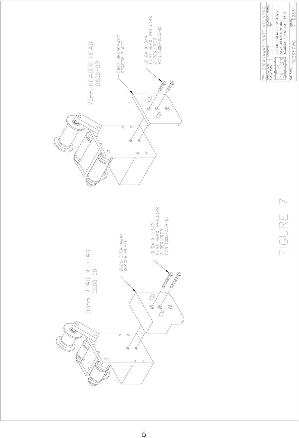
4 INSTALLATION PROCEDURE The following is a generic procedure intended to supplement the standard DTS-6/-6D Installation Manual. Timecode Reader Installation If both 35mm and 70mm readers are to be used on the same bracket, connect the proper breakaway plate to each reader as shown in Figure 7. Keep spacers attached to the readers and keep them as a set once projector alignments are made. Position the appropriate DTS mounting bracket on the same bolt pattern as the reel arm and bolt securely in place. Install the Timecode Reader onto the DTS mounting bracket and bolt into place with supplied hardware. Reinstall the reel arm on the top bolt pattern of the DTS mounting bracket. Using film, align the mounting bracket and the reel arm so that the film path through the reader and to the projector is correct. For 70mm -- 35mm reader used at the same projector - Start by mounting the 70mm reader (with its breakaway plate attached) to the bracket. Use 70mm film to align reader. Once aligned, tighten bracket screws. Loosen the thumbscrew on the breakaway plate so that the 70mm reader detaches from the bracket. - Now attach the 35mm reader (with its breakaway plate attached) to the bracket. Use 35mm film to be sure the alignment path is correct -- no corrections should be necessary. The principle is to have one alignment for both readers so that no projector adjustments are needed when the readers are exchanged. The DTS timecode reader MUST have a straight film path (no angles or twists) and at least a small amount of tension. The auxiliary flanged roller on the timecode reader head is used to avoid film walk out and helps to stabilize the film. Additional guide rollers or adding a second auxiliary roller may be installed to ensure proper film tension - most critical on platter systems. Connect the 9-pin timecode cable(s) to the DTS player(s) or failsafe board, if used. Two projector (change-over) theaters The readers must be placed at the same location on each projector. The offset value must be the same for the movie to play in sync at both projectors. 3

5 4

6 5
7 6

8 7

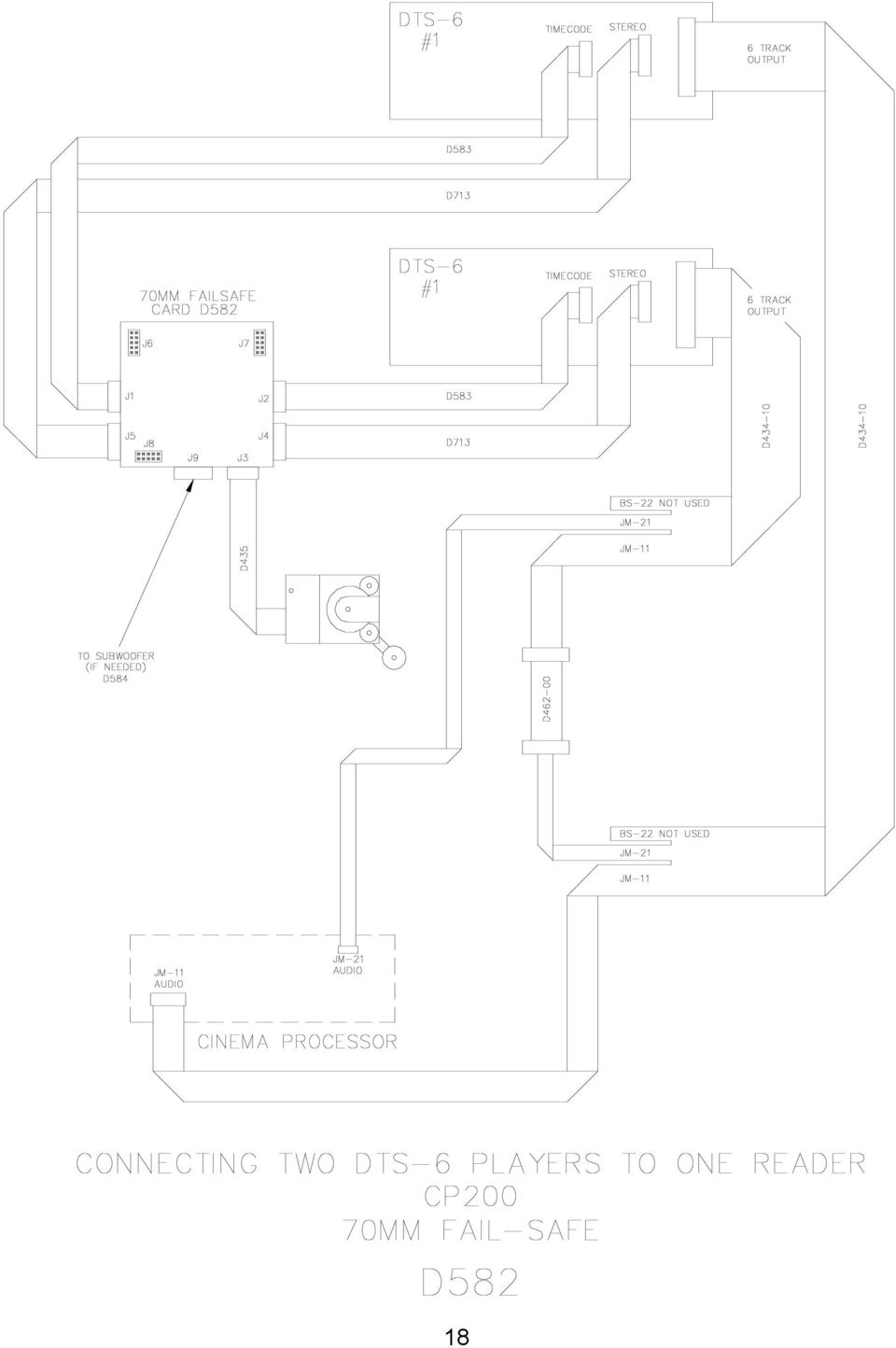
9 FAIL-SAFE INSTALLATION, DTS 70mm Requires the addition of a second DTS player. The second player must be the same model as the main player. See failsafe wiring diagrams that applies to your player. Use the failsafe board that applies to your players. Both players must be the same model. This allows a second DTS player to take over if the main DTS player fails. DTS-6 (2-drives) = DTS part number D582 DTS-6D (3-drives) = DTS part number D587 Connect all cables, including power to the players. NOTE: The DTS player is a computer based system and as such can be susceptible to power line surges. A quality surge/spike suppresser made for computers is recommended. If using one reader for two players, connect the 9-pin cables from the timecode reader to failsafe board. If using two readers and two players, connect one reader to each player, by-passing the failsafe board. Sync Adjustment For DTS 70mm A special leader of DTS 70mm film is included with each DTS 70mm reader head. This allows the offset to be measured. Offset settings for DTS 35mm will not be the same as DTS 70mm. Leave a label on player with value for each setting. Install the 70mm reader head(s). To set the sync, thread DTS 70mm offset leader through the projector and reader. Put 00 at the reader s lens. Read the number at the picture aperture and adjust the OFFSET switches (on the DTS players) for this number. If the special leader is not available, the frame-count method can be used. Thread some 70mm film through the DTS 70mm reader and the projector. Count the number of picture frames from the DTS reader lens to the projector s picture aperture. Multiply the result by 1.25 and subtract one. Set the player s TIMECODE HEAD OFFSET switches to this number. EXAMPLE: 27 frames X 1.25 = = offset. Round this number off to the next whole number. So, 33 would be your offset number. Audio Level Adjustment *** The DTS 35mm film cannot be used to set the offset *** Set master fader to 7. Use a SPL meter (set for slow & C-weighted) and the DTS DS1 Setup disc to set levels in the theater. Stand in rear third of theater and just off center. Set DTS levels for both players to L, C, R = 85dB, LS & RS = 82dB, and sub bass = 91dB. *** Both DTS Players level and OFFSET (sync) settings must match *** 8

10 FAIL-SAFE TEST Note: Analog fallback not used on DTS 70mm film. Listen Test Thread DTS 70mm encoded film through the projector and DTS reader(s). Load matching CD-ROM discs into the two DTS players: One disc (set) in the main unit and the second in the fail-safe player. Start the projector. The cinema processor should pulse to digital and both players should be playing in digital. Their SYSTEM lights should be blinking and DIGITAL lights should be on solid. Turn up the booth monitor so that the sound track is heard. While playing in DTS, eject the discs from the main player. The second (or failsafe ) player should immediately take over. No interruption in sound should be heard. Load discs back into the main player. Once the main player starts playing in digital, eject the disc from the fail-safe player. No sound interruption should be heard. Run a reel of DTS 70mm film. The green light on the reader should brighten when timecode is read. The light should be bright and steady, and not flashing. A lot of flashing indicates a problem. Go into the theater to verify quality sound and a comfortable listening level. Also, verify good lip sync. OPERATION Thread Film Through The DTS Timecode Reader Verify same size loops through the projector as done when checking the offset number. Failure to do so will result in the picture being out of sync with the digital sound track. Verify Offset If the DTS reader has been changed from 35mm to 70mm (or visa-versa), remember to change the offset setting on the DTS player. Failure to do so will result in the picture being out of sync with the digital sound track. Verify Movie Discs Verify the discs match the movie ( Jurassic Park film with Jurassic Park movie discs). If the film and discs don't match, the digital sound track will not play. If a second DTS player is used for 70mm fail-safe, load a second set of discs into this unit. These discs should match the discs in the main DTS player. Reboot players to ensure the discs are read by the players. DTS recommends the show be pre-run. Check that the timecode reader green LED is bright and steady, and the system performs properly. Check all reels for good timecode, if time permits. Occasional blink of the TIMECODE LED is normal. Maintenance The timecode reader s lens should be blown off with compressed air once a day to remove any dust build up. The CD-ROM drives may be cleaned using a CD-ROM cleaning disc available at any computer store or from DTS. 9
 player should immediately take over.")
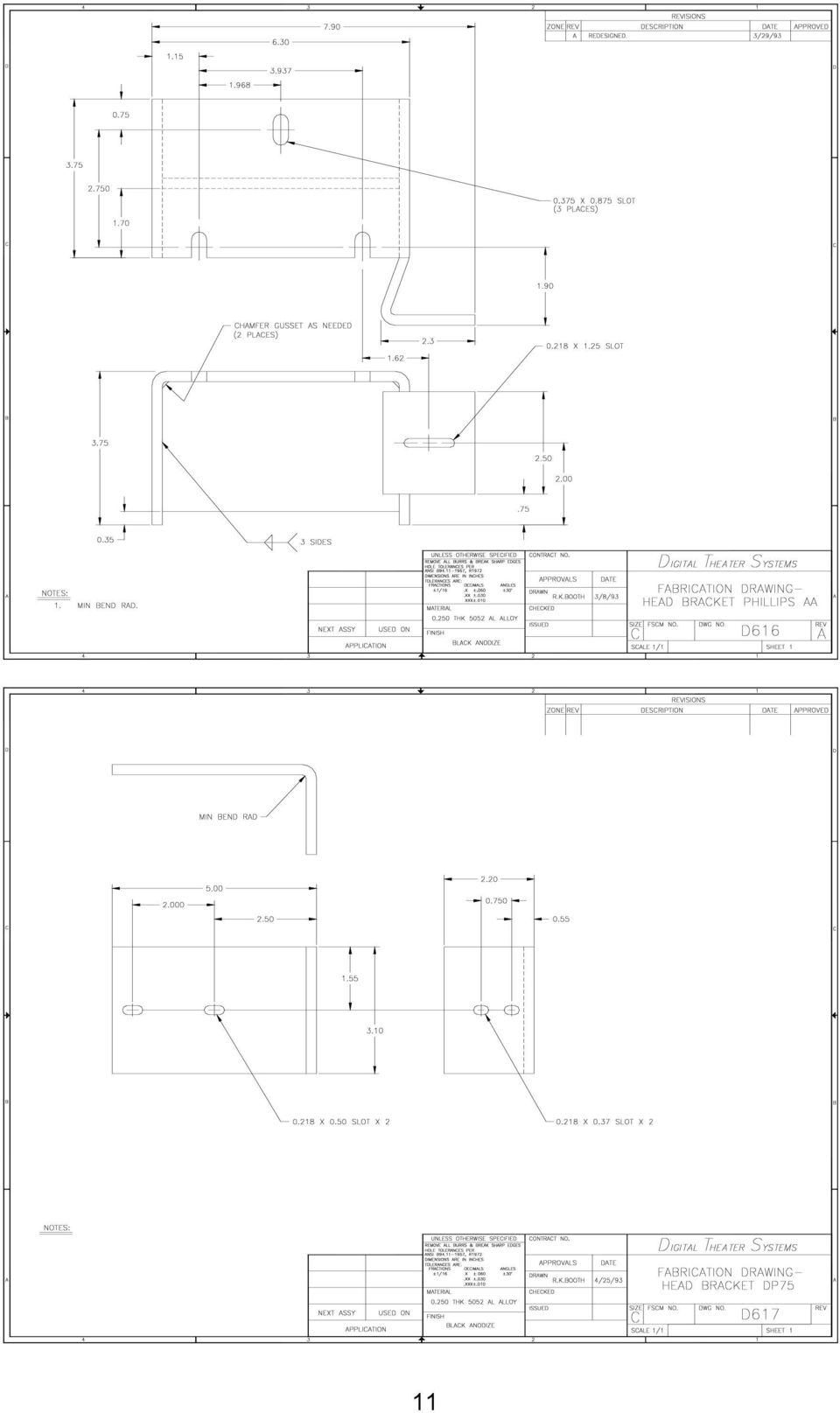
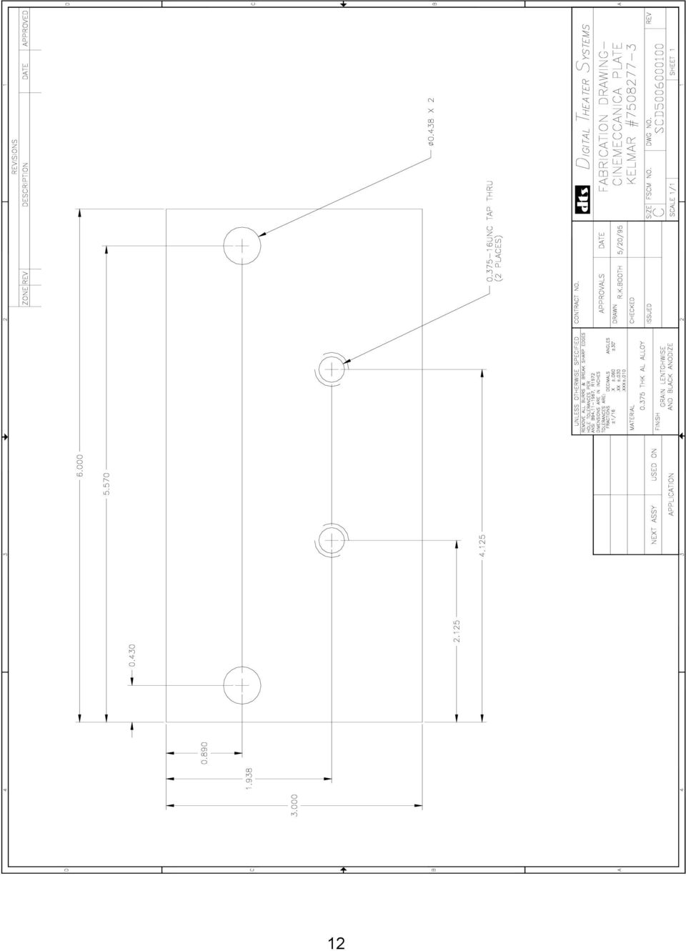
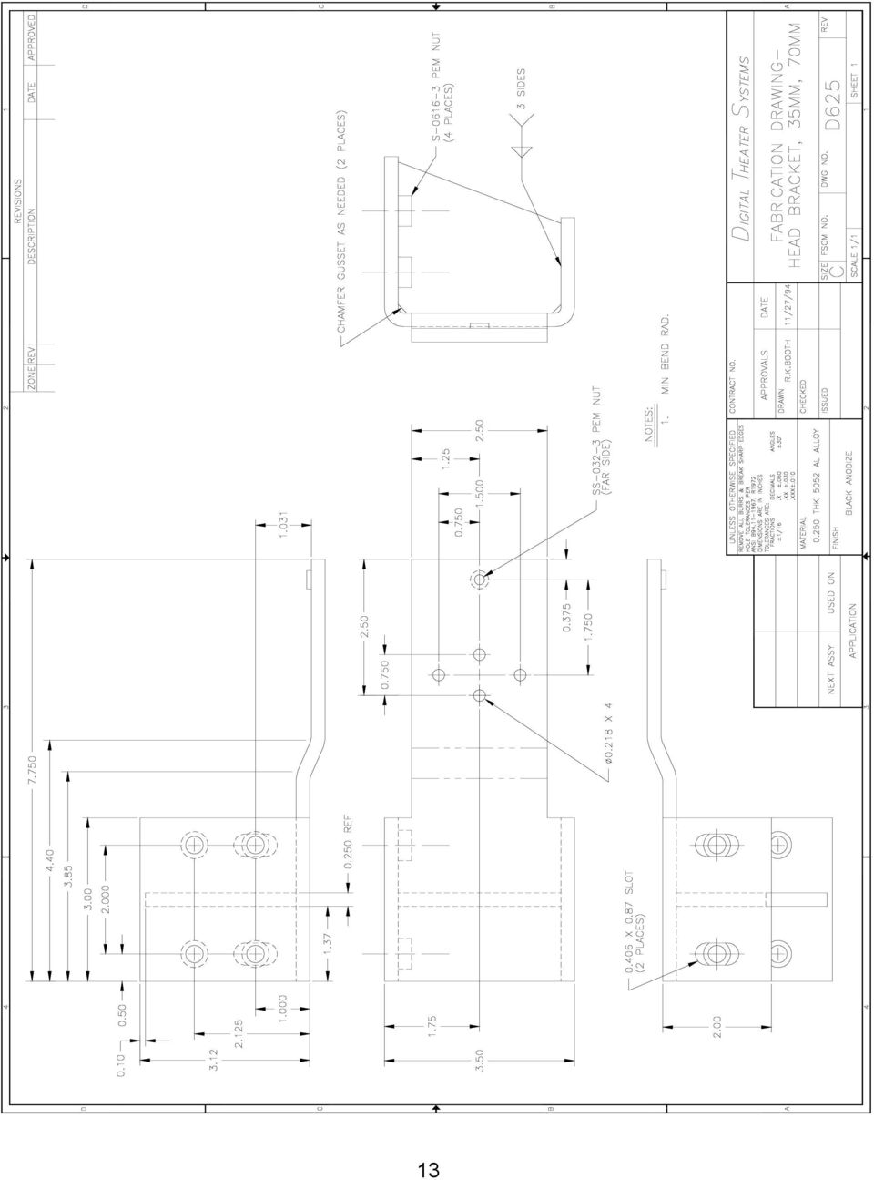
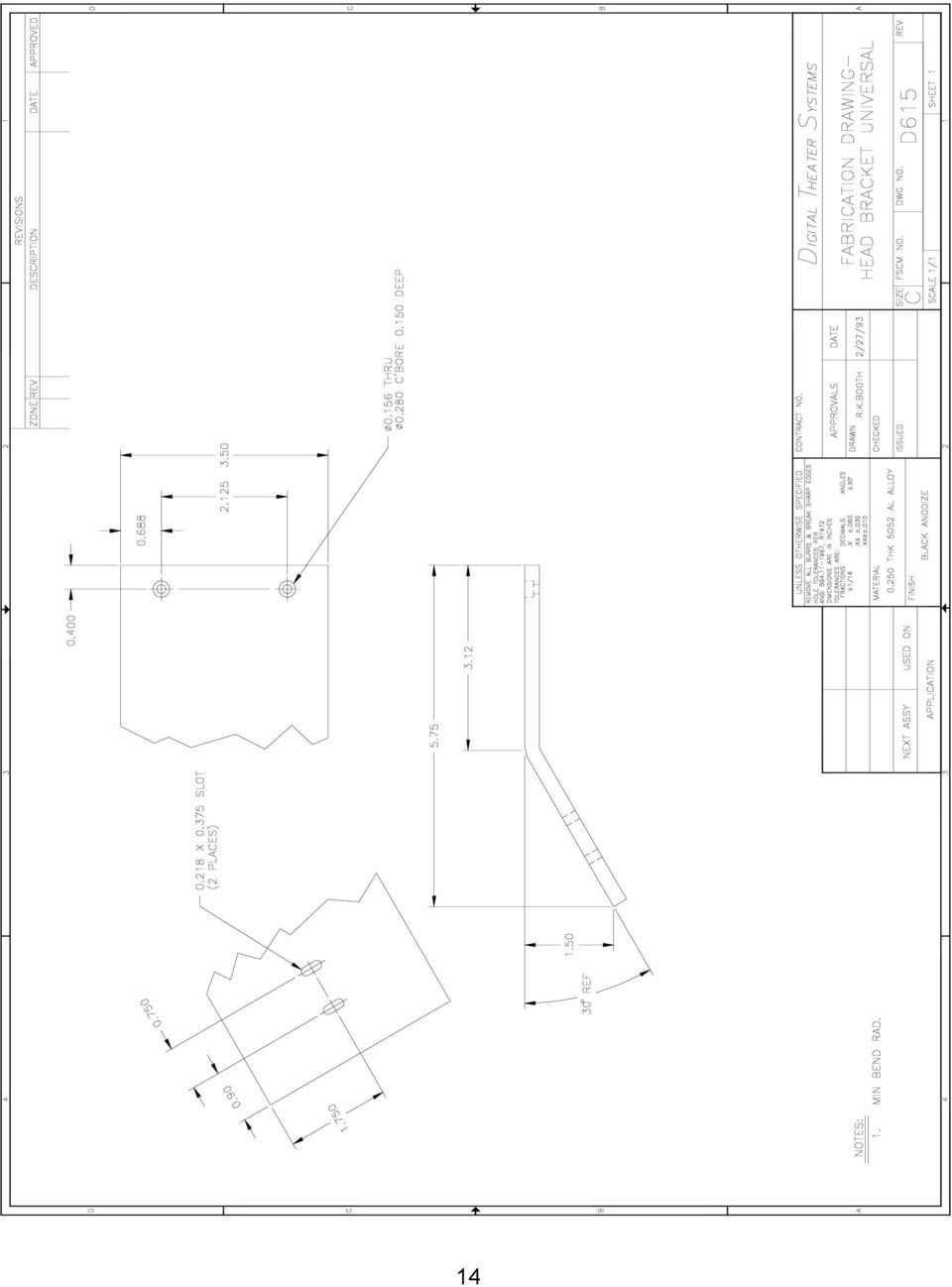
11 INSTALLATION DIAGRAMS Brackets for the DTS Timecode Reader, 70mm permanent or 35mm/70mm switchable. If switchable desired, breakaway adapters needed on brackets and readers. D625 Standard Breakaway Bracket For projectors: Century, Simplex, and Cinemeccanica with Kelmar bracket. Intended to fit between the projector and reel arm. Readers must have D626 or D627. No bracket breakaway adapter needed. Made using American standard size hole to accommodate 2 center spacing 3/8-16 tap that is utilized to mount the American made upper reel arms. Hardware included: Application QTY Description 35mm x 1/2 Phillips screws 35mm 2 3/4 x 16 x 1 hex bolt nuts 35mm / 70mm 2 3/8 lock washers 70mm 2 3/8 x 1 1/2 Phillips screws 70mm 2 3/8 flat washers 70mm 2 3/8 hex nuts Cinemeccanica Adapter Plate For Cinemeccania projectors. Used to allow the use of the D625 standard bracket. If the reel arm needs to be remounted, two plates are required. D615 - DP70 Universal Bracket Used for American projectors with a penthouse. Needs D628 adapter plate for breakaway use. Comes with tap and drill bit 8-32, and the following hardware: QTY Description x 1/2 Phillips screws 2 3/4 x 16 x 1 hex bolt nuts 2 3/8 lock washers D616 - AA2 bracket For Norelco AA projectors. Needs D628 adapter plate for breakaway use. Hardware included: QTY Description 2 #10 lock washers 3 5/16 x 18 x 5 Phillips screws 3 3/8 lock washers x 1/2 Phillips screws D617 L Bracket For Kinoton, Norelco DP75 projectors. Needs D628 adapter plate for breakaway use D628 - Breakaway Adapter Plate for Brackets Used to mount the DTS timecode reader to the side of the projector. Comes with same hardware as the D625. Adapts D617 for breakaway use. Reader must have D626 or D627. Hardware included: Qty 2, x ¾ flat head Phillips screws. D626 - Spacer (breakaway adapter) Plate for DTS 35mm Reader. Hardware included: Qty 2, x 1 ¼ flat head Phillips screws. D627 - Spacer (breakaway adapter) Plate for DTS 70mm Reader. Hardware included: Qty 2, x 5/8 flat head Phillips screws. 10

12 11
13 12
14 13
15 14
16 15

17 16

18 17

19 18
20 19

21 20
22 21
23 22
24 DTS-6 (2-drive player) Failsafe Failsafe kit E165 DTS 70mm Parts List DTS-6 70mm failsafe, upgrade kit (does not include a second player) Failsafe kit parts (these parts are in the E165 kit) D582 Interface logic board, 2/DTS-6, 70mm fail-safe (includes laminated sheet) D Interface audio cable, loop-thru D586 D582-J8 cable, failsafe automation D584 D582-J9 cable, failsafe subwoofer D583 D582-J2 & -J1 cable, failsafe timecode (2/ D582 board) D713 D582-J4 & -J5 cable, failsafe digital (2/ D582 board) DTS-6D (3-drive player) Failsafe Failsafe kit E169 DTS-6D 70mm failsafe, upgrade kit (does not include a second player) Failsafe kit parts (these parts are in the E169 kit) D587 Interface logic board, 2/DTS-6D, 70mm fail-safe (includes laminated sheet) D587-J8 & -J5 cables, failsafe audio/logic, not needed for CP200 (2/ D587 board) D D587-JM11 & -JM21 cables, failsafe audio, CP200 only (2/ D587 board) D D587-J9 cable, failsafe timecode Test Equipment and 70mm Timecode Reader Track SETUP Disc Rev. DS Empirical Test Disc, dated June 7 97 D mm Timecode Reader (auxiliary roller attached) E163 70mm auxiliary roller mm offset adjustment (sync) measurement film CD-ROM drive cleaning disc Mounting Brackets For Timecode Reader (includes hardware), permanent 35mm or 70mm D614 Standard bracket (Century, Simplex, Ballantyne) D616 Phillips AA bracket (Norelco) D617 L bracket (Kinoton, Victoria) D622 Front mount bracket (use with Dolby SR-D TM or Sony SDDS TM readers) Cinemeccanica bracket (use with D614 ) E102 70mm spacer kit (used to install a DTS 35mm reader in a 70mm space) Mounting Brackets For Timecode Reader (includes hardware), switchable 35mm / 70mm D615 Universal bracket D625 35/70mm standard bracket, use with breakaway plates D628 Adapter panel for D617 L bracket, use with breakaway plates D626 Breakaway ( spacing block ) plate for 35mm DTS reader head D627 Breakaway ( spacing block ) plate for 70mm DTS reader head
DTS-6 /-6D System Testing
 DIGITAL THEATER SYSTEMS, INC. Digital Sound For Movies DTS-6 /-6D System Testing And Troubleshooting August 1999 Digital Theater Systems, Inc. 5171 Clareton Drive DTS SA, UK Agoura Hills, CA 91301 USA
EZ-Steer Assisted Steering System
 EZ-Steer Assisted Steering System Installation Instructions Platform Kit P/N 53059-54 Case IH CVX 1135 CVX 1145 CVX 1155 CVX 1170 CVX 1190 CVX 1195 CVX 135 CVX 145 CVX 155 CVX 175 CVX 195 New Holland TVT
ECM-D70T / ECM-D70T1.5
 Elliptical Ceiling Dual Mount for 37 to 50 Flat Panels INSTALLATION INSTRUCTIONS CREATING POSITIVE CUSTOMER EXPERIENCES 9531-041-001-01 Contents ECM-D70T / ECM-D70T1.5 Installation Tools... 3 Parts List...
Small Flat Panel Lift Arm FSA-1004 and KSA-1004
 I N S T A L L A T I O N I N S T R U C T I O N S Small Flat Panel Lift Arm FSA-1004 and KSA-1004 The Lift Arm is an accessory that can be used with a broad range of Small Flat Panel Displays. The allows
LIFT-505. BMF Lift Kit. Yamaha Drive Gas or Electric. Installation Instructions
 LIFT-505 BMF Lift Kit Yamaha Drive Gas or Electric Installation Instructions Contents of LIFT-505 Yamaha Drive BMF Lift Kit: a (1 ea.) BMF A-Arm Assembly b (1 ea.) Driver Side Shock Tower c (1 ea.) Passenger
Elo Touch Solutions Wall-mounting Kit for the 5501L IDS Touchmonitors
 Installation Manual Elo Touch Solutions Wall-mounting Kit for the 5501L IDS Touchmonitors SW602206 Rev B Table of Contents Chapter 1: Safety Warning... 3 Chapter 2: Kit Contents... 4 Included in Kit...
AstroSystems Digital Setting Circles for Zhumell, GSO, Apertura and Astro-Tech
 AstroSystems Digital Setting Circles for Zhumell, GSO, Apertura and Astro-Tech Components 1 Sky Commander Digital Setting Circle Computer 2 Encoders 10,000 step 1 Sky Commander Digital Setting Circle Manual
PRS Y-axis EChain Installation
 PRS Y-axis Energy Chain Installation Page -1- PRS Y-axis EChain Installation This document shows how to install the Energy chain (Echain) on the Y-axis on ShopBot PRS and PRS BT models. Note that the dust
6 inch A-Arm Lift Kit WARNING: 16-018/16-019. installation instructions. will fit CLUB CAR DS. included:
 Revised May 205 6-08/6-09 6 inch A-Arm Lift Kit will fit CLUB CAR DS installation instructions included: Rear Lift Blocks Main Suspension Assembly Spindles A-Arms Rear Shock Mounting Plates U-Bolts WARNING:
MGB Chrome Bumper Conversion
 MGB Chrome Bumper Conversion Installation Instructions For 1974 1/2-1980 MGB This kit requires cutting, welding, and painting. Professional installation recommended. Note: Every MGB body is slightly different
Installation Instructions for FT-10 Network PowerCommand ATS Communication Module (NCM) Kits 541 0812 and 541 0868
 Kits 541 0812 and 541 0868") Instruction Sheet 10-2004 Installation Instructions for FT-10 Network PowerCommand ATS Communication Module (NCM) Kits 541 0812 and 541 0868 PowerCommand is a registered trademark of Cummins Inc. InPower
Instruction Sheet 10-2004 Installation Instructions for FT-10 Network PowerCommand ATS Communication Module (NCM) Kits 541 0812 and 541 0868 PowerCommand is a registered trademark of Cummins Inc. InPower
CINEMA SB100 powered soundbar speaker
 CINEMA SB100 powered soundbar speaker quick-start guide Thank You For Choosing This JBL Product The JBL Cinema SB100 powered soundbar speaker is a complete, integrated sound system that will dramatically
TS93 EMR T/PT/TDE. Surface applied door closer
 TS EMR T/PT/TDE Surface applied door closer Installation instructions: Pull side track mount door closer with smoke detector (EMR T) Push side track mount door closer with smoke detector (EMR PT) Double
OPL BASIC. Dosing System for Professional Laundry machines. Contents
 OPL BASIC Dosing System for Professional Laundry machines Contents 1 Getting Started. Page 2 2 Installation. Page 4 3 Set Up & Operation. Page 8 4 Maintenance & Accessories. Page 10 5 Troubleshooting Page
GAERTNER SCIENTIFIC CORPORATION 3650 Jarvis Ave. Skokie, Illinois 60076 U.S.A. tel: 1 847 673-5006 fax: 1 847 673-5009 email@gaertnerscientific.
 7109-C-244E-R1 Field Installation of HeNe Laser in B, C, and D-Type Auto Gain Ellipsometers GAERTNER SCIENTIFIC CORPORATION 3650 Jarvis Ave. Skokie, Illinois 60076 U.S.A. tel: 1 847 673-5006 fax: 1 847
PRS X-axis E-chain installation: For tools with a 12 Z-Axis
 PRS X-axis Energy Chain (Echain) Installation Page -1- PRS X-axis E-chain installation: For tools with a 12 Z-Axis This kit is compatible with PRS Shopbots that have an X-axis cutting area of 96 to 144.
CETAC Z-Drive Assembly
 CETAC Z-Drive Assembly Replacement Guide Manual Part Number 610144 Rev 1, 2012 CETAC Technologies, Printed in USA Overview This guide describes the necessary steps to replace the Z-drive assembly on your
ATS Overhead Table Shelf System INSTRUCTION MANUAL
 ATS Overhead Table Shelf System INSTRUCTION MANUAL ATS Overhead Table Shelf System Instruction Manual Warranty Newport Corporation warrants this product to be free of defects in material and workmanship
R O A D M A S T E R, I N C.
 R O A D M A S T E R, I N C. ROADMASTER, Inc. 6110 NE 127th Ave. Vancouver, WA 98682 6 13 11 MOUNTING BRACKET KIT Cable Tab 14 12 7 15 9 Cable Tab 360-896-0407 fax 360-735-9300 www.roadmasterinc.com ITEM
BUILT-IN DISHWASHER INSTALLATION INSTRUCTIONS
 BUILT-IN DISHWASHER INSTALLATION INSTRUCTIONS PLEASE READ COMPLETE INSTRUCTIONS BEFORE YOU BEGIN LEAVE INSTALLATION INSTRUCTIONS AND USER'S GUIDE WITH OWNER ALL ELECTRIC WIRING AND PLUMBING MUST BE DONE
RAIN COLLECTOR S HELF MANUAL
 RAIN COLLECTOR S HELF MANUAL The Rain Collector Shelf provides a good mounting support for your Rain Collector II. The Rain Collector Shelf is designed to be attached to Davis Sensor Mounting Arm, and
20000068 WIRELESS REMOTE ASSEMBLY, 24VDC, 1 TRANS,1 REC
 20000068 WIRELESS REMOTE ASSEMBLY, 24VDC, 1 TRANS,1 REC Fitment to MP-25 620 CR 4841, Haslet, TX 76052 Ph 817.439.1108 Fax 817.636.5675 www.machine-technologies.com Kit contents 1 Transmitter 2 button,
Pulleys and Belt. Install the Major Accessory and Pulley. Install the Motor Pulley NOTE. Align the Motor Pulley and the Tool Pulley NOTE
 Pulleys and Belt Pulley Guard - 505862 Install the Major Accessory and Pulley 1. Place the short end of the mounting base holes, and insert - but don t tighten - the setscrews. If the Major Accessory has
INSTALLATION AND OPERATING INSTRUCTIONS For Model GL1 Gate Locks
 Securitron Magnalock Corp. www.securitron.com ASSA ABLOY, the global leader Tel 800.624.5625 techsupport@securitron.com in door opening solutions INSTALLATION AND OPERATING INSTRUCTIONS For Model GL1 Gate
GEH6290. Mechanism Circuit Breaker. Handle Operating Mechanism Cat. No. Type NEMA 1, 3R, 12, 13 NEMA 4/4X Cat. No. Cat. No. Series Instruction
 GEH6290 g Cable Operator Mechanisms for E150, SE150, SF250, and SG600 Spectra RMS Circuit Breakers Type SCH1/1X, SCH2/2X Flange-Mounted Handle Assemblies, Cable Series SC3L SC10L and Type SC0M1A, SCOM1EF,
In-Ground Basketball System Owners Manual
 In-Ground Basketball System Owners Manual Customer Service Center N53 W4700 South Corporate Circle Sussex, WI 53089 U.S.A. Write Model Number From Box Here: WARNING! 3 Capable Adults REQUIRED TOOLS AND
DB 18 & DB 18E Options
 DB 8 & DB 8E Options Assembly Manual Boom Truss Element Truss 6m Passive Inventory check DB 8 & DB 8 E Boom Truss Kit 7-004-0 QTY Part # Description 6 60-0045 /6 wire clips 4 60-0048 /6 Thimble 4 60-0044
Installation Manual. SKU# 21000 series (Base Rails) SKU# 22000 series (Overhead Racks)
 SKU# 22000 series (Overhead Racks)") Installation Manual SKU# 21000 series (Base Rails) SKU# 22000 series (Overhead Racks) Welcome to the world of TracRac! We re delighted that you have chosen TracRac, the ultimate sliding truck rack system.
Installation Manual SKU# 21000 series (Base Rails) SKU# 22000 series (Overhead Racks) Welcome to the world of TracRac! We re delighted that you have chosen TracRac, the ultimate sliding truck rack system.
Original Assembly Guide
 TCT Multipurpose Single Bevel Sliding Compound Mitre Saw Original Assembly Guide Read instructions before assembling this tool. Table of Contents GB Assembly Guide Read instructions before assembling this
Rollator Cane and Brake Replacement SAFETY SUMMARY (CONTINUED)
") Rollator Cane and Replacement Assembly, Installation and Operating Instructions SAVE THESE INSTRUCTIONS NOTE: Check ALL parts for shipping damage. If shipping damage is noted, DO NOT use. Contact Carrier/Dealer
Rollator Cane and Replacement Assembly, Installation and Operating Instructions SAVE THESE INSTRUCTIONS NOTE: Check ALL parts for shipping damage. If shipping damage is noted, DO NOT use. Contact Carrier/Dealer
AM/FM ANTENNA RELOCATION KIT
 -J0 REV. 008-09-0 AM/FM ANTENNA RELOCATION KIT GENERAL Kit Number 766-09 Models This kit is used to relocate a fender-mounted AM/FM antenna to a Detachable Tour-Pak on specific model motorcycles. For model
4 in 1 Strength Station
 Revision 0 September 2010 4 in 1 Strength Station Owner s Manual Record Serial Number Here Platinum by Tunturi www.tunturi.com Date www.tunturi.com of Purchase 4 in 1 Strength Station Owner s Manual Instructions
Replacing a Vantage Vue Transmitter
 Replacing a Vantage Vue Transmitter Included in this replacement transmitter kit: SIM transmitter Cable tray Instructions Tools Required Phillips head screwdriver Small pliers To replace the transmitter
2008 ACCORD - Front Knuckle/Hub/Wheel Bearing Replacement (page 18-13)
") 2008 ACCORD - Front Knuckle/Hub/Wheel Bearing Replacement (page 18-13) Exploded View Special Tools Required Ball joint remover, 28 mm 07MAC-SL0A202 Hub dis/assembly tool 07GAF-SD40100 Bearing driver attachment,
2008 ACCORD - Front Knuckle/Hub/Wheel Bearing Replacement (page 18-13) Exploded View Special Tools Required Ball joint remover, 28 mm 07MAC-SL0A202 Hub dis/assembly tool 07GAF-SD40100 Bearing driver attachment,
SLACK PERFORMANCE KARTS
 SLACK PERFORMANCE KARTS SET UP GUIDE Thank you for purchasing a 2013 Slack Axiom Chassis. Performance Mfg. strives to provide you with the very best chassis and components on the market today. Your satisfaction
SERVICE MANUAL. Corpus 3G. Seat system for electric wheelchair
 SERVICE MANUAL US Corpus 3G Seat system for electric wheelchair How to contact Permobil Head Office of the Permobil group Produced and published by Permobil AB, Sweden Version 4, 2014-07 Item No.: 205260-US-0
Wiper Motor Marinco 2.5. Installation Instructions
 Wiper Motor Marinco 2.5 Installation Instructions Wiper Motor Marinco-2.5 The Marinco 2.5 Wiper Motor Offers the Following Features: Fully sealed base and housing which allows installation in outdoor wet
HP UPS R1500 Generation 3
 HP UPS R1500 Generation 3 Installation Instructions Part Number 650952-001 NOTE: The rating label on the device provides the class (A or B) of the equipment. Class B devices have a Federal Communications
SECURITY SYSTEM SMART SIREN KIT
 -J00876 REV. 009-0-09 SECURITY SYSTEM SMART SIREN KIT GENERAL Kit Number 688-0 Models For model fitment information, see the P&A Retail Catalog or the Parts and Accessories section of www.harley-davidson.com
EZ-Steer Assisted Steering System Installation Instructions Platform Kit P/N 53059-21
 EZ-Steer Assisted Steering System Installation Instructions Platform Kit P/N 53059-21 Case IH MXU 100 Pro MXU 110 Pro MXU 115 Pro MXU 125 Pro MXU 135 Pro MXU 100 X Line MXU 110 X Line MXU 115 X Line MXU
Micro Cart User's Guide
 Micro Cart User's Guide To take full advantage of the ergonomic features of your new Sun Mountain Micro Cart, please read the following information. SUN MOUNTAIN 1 Your Micro Cart has several innovative
ReachFree ID Installation Instructions For Portal TI, Sentinel and C-Start. Unitec www.startwithunitec.com
 ReachFree ID Installation Instructions For Portal TI, Sentinel and C-Start Unitec www.startwithunitec.com Proprietary Information and Materials of Unitec, Inc. Such proprietary information and materials
BBWX1 Satellite Weather Receiver. Installation and Maintenance Guide
 BBWX1 Satellite Weather Receiver Installation and Maintenance Guide Rev FUSA 15JUL2007 Table of Contents Safety Precautions 3 Disclaimer. 3 Contents of Package. 4 Tools Required..4 Installation General
Installation instruction do88 Intercooler for Volvo S40 / V50 / C30
 Installation instruction do88 Intercooler for Volvo S40 / V50 / C30 This instruction shows how to replace the OEM intercooler with our performance intercooler. 2. 3. 1. 4. 5. Part number: ICM-170 6. At
Depending on which elastic support you have you can secure the V2 power unit to the following seat bracket tubes: EXTERNAL DIAMETER 27.
 ASSEMBLY 1 - EPS V2 POWER UNIT (SOLUTION 5) 1.1 - POSITIONING INSIDE THE SEAT TUBE WITH ELASTIC SUPPORT IN THE SEAT BRACKET TUBE Depending on which elastic support you have you can secure the V2 power
KEYLESS ENTRY UPGRADE SECURITY SYSTEM for 2004 TOYOTA HIGHLANDER
 KEYLESS ENTRY UPGRADE SECURITY SYSTEM for 2004 TOYOTA HIGHLANDER DEALER SERVICE AND INSTALLATION MANUAL KIT NO. 00016-30915 Contents PARTS LIST... 2 PARTS ILLUSTRATIONS... 2 VEHICLE PREPARATION... 3 INSTALLING
Part Name/Description Part Number Quantity. Power Cable 4000950-5 1
 Note: Indented items indicate parts included in an assembly listed above Part Name/Description Part Number Quantity Power Cable 4000950-5 1 Raven Harness Adapter Kit 4100525 1 Installation Instructions
FTC 2015-2016 DIY Mountain Build Guide
 FTC 2015-2016 DIY Mountain Build Guide Assembly Instructions Check out the DIY2015-2016 Prints and BoM for individual part details. Release 1.0 9/10/15 Page 1 This guide and Bill of Materials are for constructing
MUSTANG II IFS COMPLETE PARTS PACKAGE
 MUSTANG II IFS COMPLETE PARTS PACKAGE Your Southern Rods & Parts Mustang II IFS Parts Package contains the following items: 1 pr) Upper Control Arms (2023) 1) Upper Arm Bolt Kit (MP-001-A) 1 pr) Lower
TECHNICAL INFORMATION
 TECHNICAL INFORMATION Models No. 2012NB Description 304mm (12") Automatic Thickness Planer CONCEPTION AND MAIN APPLICATIONS * Compact and light weight (27 Kg./59 lbs) automatic thickness planer for easier
SB-C-CTS/10TW3 SKU# 94552 2008 & Up Cadillac CTS/CTS-V
 INSTALLATION GUIDE for the SB-C-CTS/10TW3 SKU# 94552 2008 & Up Cadillac CTS/CTS-V If you choose to perform the installation yourself, it is absolutely vital that the Stealthbox be properly mounted to the
2M IR Mini Dome Quick Installation Guide
 2M IR Mini Dome 2M IR Mini Dome Quick Installation Guide Please follow the installation steps below to set up 2M IR Mini Dome IP Camera. Check the package contents against the list below. See P.1 Physical
Master Code 2. Troubleshooting: Installation 7. Troubleshooting: Door Jamming and Door Handing 8. Troubleshooting: Keypad 12
 Programming and Troubleshooting Guide 1 2 3 4 5 6 Master Code 2 Troubleshooting: Installation 7 Troubleshooting: Door Jamming and Door Handing 8 Troubleshooting: Keypad 12 Troubleshooting: Battery 13 Battery
2003/2004/2005 TOYOTA COROLLA
 2003/2004/2005 TOYOTA COROLLA KEYLESS ENTRY UPGRADE SECURITY SYSTEM INSTALLATION INSTRUCTIONS KIT NO. 00016-30120 SPECIAL NOTE: Installation Sequences After TMS and Safety mandated preparatory steps have
TABLE OF CONTENTS. I. TROUBLESHOOTING... 2 - Section 1.01: Common Problems/Solutions... 2
 BAL Accu-Slide System I. Table of Contents TABLE OF CONTENTS I. TROUBLESHOOTING... 2 - Section 1.01: Common Problems/Solutions... 2 II. GETTING STARTED... 5 - Section 2.01: Tools You Will Need... 5 - Section
SECTION G2: CABLE PROCESSOR MODULE MAINTENANCE
 SECTION G2: CABLE PROCESSOR MODULE MAINTENANCE Cable Processor Module overview WARNING! When tipping the Cable Processor Module back, (after removing the toggle arm pin), use extreme caution not to drop
AM/FM ANTENNA KIT (TOUR-PAK MOUNT)
") -J077 REV. 008-0-0 AM/FM ANTENNA KIT (TOUR-PAK MOUNT) GENERAL Kit Number 7-98A Models For model fitment information, see the P&A Retail Catalog or the Parts and Accessories section of www.harley-davidson.com
-J077 REV. 008-0-0 AM/FM ANTENNA KIT (TOUR-PAK MOUNT) GENERAL Kit Number 7-98A Models For model fitment information, see the P&A Retail Catalog or the Parts and Accessories section of www.harley-davidson.com
EXPLORE 4-Leg Teaming Table with Screen Share Assembly Instructions
 EXPLORE 4-Leg Teaming Table with Screen Share Monitor Display Requirements: your flat panel display must confirm to the following requirements. y With the stand removed, the monitor must not exceed 40
Oceanscience Cable Chimp II Cableway ROV System User Guide and Warranty
 Oceanscience Cable Chimp II Cableway ROV System User Guide and Warranty Page 1 Table of Contents Introduction Page 3 Overview Page 3 Setup and Operation Page 5 Remote Control Page 6 Power Management Page
DIY Y6. Build Manual V.A 2014
 DIY Y6 Build Manual V.A 2014 1 Contents Thanks for purchasing a DIY Y6! These instructions will show you how to assemble a Y6 using the Pixhawk autopilot system and ArduCopter/APM:Copter firmware. If you
Go-kart for little race-drivers
 Go-kart for little race-drivers Drill and drive. Go-kart What it lacks in speed, it more than makes up for in fun: the go-kart will excite little race-drivers. 1 Introduction It s only a go-kart, but it
Char-Lynn Hydraulic Motor. Repair Information. 10 000 Series. October, 1997
 Char-Lynn Hydraulic Motor October, 1997 Repair Information Geroler Motor Two Speed 001 27 Retainer inside bore of valve plate bearingless motors only 4 15 16 3 6 35 Parts Drawing 25 2 2 1 19 17 36 40 47
Installation Instructions HighRock 4x4 TM
 Installation Instructions HighRock 4x4 TM Slider Step Vehicle Application: Jeep YJ and TJ Wrangler 1986 2006 Part Number: 49312 www.bestop.com - We re here to help! Visit our web site and click on Ask
INSTALLATION INSTRUCTIONS
 Turbo Tube Slide INSTALLATION INSTRUCTIONS C A U T I O N Do not climb on the outside of the slide This slide is designed for home use only, not for Public Playgrounds PlayCore, Inc. 2004 Copyrighted Material.
DirectCommand Installation DirectCommand 3-Channel Spreader Kit
 Note: Indented items indicate parts included in an assembly listed above Part Name/Description Part Number With Switch Box Quantity With Remote Switch Display Cable Kit 4100814 1 1 Power Control Relay
Senses SV series industrial monitor user manual
 Industrial Monitors Senses SV series Senses SV19 / SV17 User manual (Issue A) Part No: 85090084 Page 1 of 25 Copyright Copyright 2008 Amplicon Liveline Ltd. All rights reserved. This publication, including
Tools Required: Sawzall, hack saw, or small body saw, drill, ¼ drill bit, ¾ hole saw, tape measure, silicone or epoxy, & 7/16 socket.
 When installing a one-piece window kit, it is best to do it as early as possible in the restoration process. This will allow for minimal repairs if need be. Kit Contents: Glass - 2 pcs Felt channels 2
Installation Guide. Wyse D Class 4-GB RAM Upgrade Option Kit. Products: D90D7, D90DW. Issue: 121312 PN: 883884-35L Rev. A
 Installation Guide Wyse D Class 4-GB RAM Upgrade Option Kit Products: D90D7, D90DW Issue: 121312 PN: 883884-35L Rev. A Copyright Notices 2012, Wyse Technology Inc. All rights reserved. This manual and
Rebuild Instructions for 70001 and 70010 Transmission
 Rebuild Instructions for 70001 and 70010 Transmission Brinn, Incorporated 1615 Tech Drive Bay City, MI 48706 Telephone 989.686.8920 Fax 989.686.6520 www.brinninc.com Notice Read all instructions before
Competition 4 & 6 suspension Lift Toyota Landcruiser & nissan patrol
 Competition 4 & 6 suspension Lift Toyota Landcruiser & nissan patrol Competition suspension Product Guidelines Guidelines for sale and recommendation of 4 (100mm) and 6 (150mm) Lifts for Toyota Landcruiser
INSTALLATION INSTRUCTIONS MULTI-MOUNT KIT Part Number: 75330 Application: Warn HP PowerPlant P/N 71800
 INSTALLATION INSTRUCTIONS MULTI-MOUNT KIT Part Number: 75330 Application: Warn HP PowerPlant P/N 71800 Your safety, and the safety of others, is very important. To help you make informed decisions about
R O A D M A S T E R, I N C.
 R O A D M A S T E R, I N C. 6 28 1 2 "ā 1 2 " 4 8 ITEM QTY NAME PART # 1...4...1/2 x 1 1/4 BOLTS... 350094-00 2...4...1/2 LOCK WASHER... 350309-00 3...4...1/2 HEX NUT... 350258-00 4...2...SPACER PLATE...
1500 Follow Spot Yoke
 = 1500 Follow Spot Yoke Rev 1.1 2004 City Theatrical, Inc. Getting Started with the City Theatrical Follow Spot Yoke Congratulations on the purchase of your City Theatrical Follow Spot Yoke. The City Theatrical
PRODUCT: WASHER / WASHER-DRYER COMBO MODEL: AW 120 / AW 122 / AW 125 AWD 120 / AWD 121 / AWD 129
 PRODUCT: WASHER / WASHER-DRYER COMBO MODEL: The information included in this Splendide Repair Manual may change without notice. Please see our web site www.splendide.com/service/docs.html for updates,
Front brakes (FN- 3), servicing
, servicing") j a t Front brakes (FN- 3), servicing 46-1 Front brakes, servicing Note: Install complete repair kit. After replacing brake pads and before moving vehicle, depress brake pedal several times firmly to properly
j a t Front brakes (FN- 3), servicing 46-1 Front brakes, servicing Note: Install complete repair kit. After replacing brake pads and before moving vehicle, depress brake pedal several times firmly to properly
i ChatterBox! Motorcycle Security
 i Before you Start the Installation * Please read this manual to become familiar with the requirements necessary to complete the installation. * Use a high quality multi-meter to test all wires before
Back-Up Camera Installation Guide
 Hz Hz In This Guide: Back-up camera installation requires connecting power wiring to the existing reverse lighting circuit and adding a chassis ground, as well as routing a video signal cable to the front
R O A D M A S T E R, I N C.
 R O A D M A S T E R, I N C. MOUNTING BRACKET KIT 14 8 7 4 13 5 6 ITEM QTY NAME MATERIAL 1...6...1/2" x 2 1/2" BOLT... 350099-00 2...2...1/2" x 1 1/2" BOLT... 350095-00 3...8...1/2" LOCK WASHER... 350309-00
Table of Contents WARNING SYMBOLS AND DEFINITIONS
 Table of Contents SAFETY INSTALLATION OPERATION MAINTENANCE Safety... 2 Specifications... 4 Installation... 5 Operation... 8 WARNING SYMBOLS AND DEFINITIONS Maintenance... 9 Parts List and Assembly Diagram...
Installation instructions, accessories - Handsfree for cellular phone, system B, entry level
 XC90 Section Group Weight(Kg/Pounds) Year Month 3 39 0.5/1.1 2006 07 XC90 2003, XC90 2004 IMG-249663 Page 1 of 18 Required tools A0000162 A0000163 IMG-239664 M0000232 IMG-253123 IMG-252223 Page 2 of 18
JANUS INTERNATIONAL CORPORATION INSTALLATION INSTRUCTIONS Pantheon Mini Operator
 JANUS INTERNATIONAL CORPORATION INSTALLATION INSTRUCTIONS Pantheon Mini Operator The Janus Pantheon mini operator does not typically require the provision of any additional site requirements other than
 UFO 1 FOLDER INDEX A2 FOLDING MACHINE TYPE 10060 LIST NO DESCRIPTION PAGE 10101M Main Assembly - Mechanical 2 10201M Main Roller Assembly 4 16101M Upper & Lower Perforator Shaft Assembly 6 12701M Primary
Wireless Home Security Alarm System AM 500
 Wireless Home Security Alarm System AM 500 12 MONTH GUARANTEE Installation & Operating Instructions INTRODUCTION The AM500 is a simple self-contained alarm system. It protects the home by sounding a siren
R O A D M A S T E R, I N C.
 R O A D M A S T E R, I N C. 11 10 20 12 4 18 19 1 2 13 16 ITEM QTY NAME MATERIAL 1...2... 1/2" x 3 1/2" BOLT... 350103-00 2...2... 1/2" x 2" BOLT... 350097-00 3...6... 1/2" x 1 1/2" BOLT... 350095-00 4...2...
Front Panel Board Cable Replacement Instructions
 apple Mac Pro Front Panel Board Cable Replacement Instructions First Steps 1 Shut down computer. Note: Follow these instructions carefully. Failure to do so could damage your equipment and void its warranty.
POWER LOCK KIT GENERAL INSTALLATION -J04427 REV. 2007-12-04. Kit Number. Models. Additional Parts Required. Kit Contents
 -J0 REV. 00--0 POWER LOCK KIT GENERAL Kit Number -0, 0-0 Models For model fitment information, please see the P&A Retail Catalog or the Parts and Accessories section of www.harleydavidson.com (English
R O A D M A S T E R, I N C.
 R O A D M A S T E R, I N C. ROADMASTER, Inc. 6110 NE 127th Ave. Vancouver, WA 98682 16 6 18 Cable Tab 13 15 8 10 2 Cable Tab 1 11 9 17 14 360-896-0407 fax 360-735-9300 www.roadmasterinc.com ITEM QTY NAME
Processor Cage Fans, Front and Rear Replacement Instructions
 apple Mac Pro Processor Cage Fans, Front and Rear Replacement Instructions First Steps 1 Shut down computer. Note: Follow these instructions carefully. Failure to do so could damage your equipment and
User manual DinaSys DTC/DTS and DTC/DTZ
 PiCommIT has developed the DinaSys DTC/DTS and DinaSys DTC/DTZ turntable controller for the Fleischmann / Marklin Turntables in scale H0, H0m, TT, N and Z. One of the most important starting point was
Mounting Tripod Kit Installation Manual
 Mounting Tripod Kit Installation Manual For use with Davis s wireless and cabled Vantage Pro2 weather stations, the Mounting Tripod simplifies installation. The tripod supports the Integrated Sensor Suite
DCF Optimized Rack System
 Integrated Cabinet Solutions For Business-Critical Continuity DCF Optimized Rack System User Manual IMPORTANT SAFETY GUIDELINES SAVE THESE INSTRUCTIONS This manual contains important instructions that
R O A D M A S T E R, I N C.
 R O A D M A S T E R, I N C. 11 4 9 28 1 2 "ā 1 2 " 10 7 13 Special tools needed: plastic pop rivet gun ITEM QTY NAME PART # 1...4... 1/2 x 1 1/4 BOLT... 350094-00 2...8... 1/2 LOCK WASHER... 350309-00
Power Cube Open Source Ecology Page 1. Power Cube. Version 4
 Power Cube Open Source Ecology Page 1 Power Cube Version 4 Power Cube Open Source Ecology Page 2 Contents Table of Contents Power Cube... 1 Contents...2 Introduction... 3 Bill Of Materials...4 Discrete
EZ-Steer Assisted Steering System
 EZ-Steer Assisted Steering System Installation Instructions Platform Kit P/N 53059-21 Case IH Puma 165 Puma 180 Puma 195 Puma 210 New Holland T7030 T7040 T7050 T7060 Revision A June 2007 Part Number 53345-21-EU2
QUICK START GUIDE. Thank you for purchasing the ButtKicker Kit. This guide will help you quickly set up your new ButtKicker Kit Contents: BK-Kit-4
 BK-Kit-4 QUICK START GUIDE Thank you for purchasing the ButtKicker Kit. This guide will help you quickly set up your new ButtKicker Kit Contents: ButtKicker Advance Remote Control Chair/Couch Mounting
DIY QUAD. Build Manual V.A 2014
 DIY QUAD Build Manual V.A 2014 1 Contents Thanks for purchasing a DIY Quad! These instructions will show you how to assemble a Quad using the Pixhawk autopilot system and ArduCopter/APM:Copter firmware.
KINO-TORSION(M) USER MANUAL
 USER MANUAL") KINO-TORSION(M) USER MANUAL CONTENTS Welcome... Page 1 Inside the Box... Page 2 Attachment of Lens to Kino-Torsion(M) Mechanism.... Page 3 Electrical Connections... Page 4 Attachment of Kino-Torsion(M)
KINO-TORSION(M) USER MANUAL CONTENTS Welcome... Page 1 Inside the Box... Page 2 Attachment of Lens to Kino-Torsion(M) Mechanism.... Page 3 Electrical Connections... Page 4 Attachment of Kino-Torsion(M)
INSTALLATION INSTRUCTIONS
 INSTALLATION INSTRUCTIONS Application Outboards Faria 5 Gauge Set* Publication No. Description Part Number Honda Code PII53606A White faced, flat lens 06300-ZW5-010ZB 6315410 Issue Date Black faced, flat
Models HD920EV HD930EV LW5000EV WD962KEV WD962KPEV WD962MLEV 349544
 .. Belt Drive Battery Backup Garage Door Opener Models HD920EV HD930EV LW5000EV WD962KEV WD962KPEV WD962MLEV 349544 FOR RESIDENTIAL USE ONLY Please read this manual and the enclosed safety materials carefully!
1. Lay out 2 pieces of 7/8" tubing and mark for bending as shown. Remember that the bend is in the shaded area as shown below in Figure 1.
 MINI BIKE PLANS Page 1 INTRODUCTION Before starting to build your Mini-Bike, be sure that you have all the parts shown on the material list. You will note that tubing has been used in the construction.