SWIMMING POOL HEAT PUMP UNITS. Installation & Instruction Manual DURA - series
|
|
|
- Claribel Caren Underwood
- 8 years ago
- Views:
Transcription
1 SWIMMING POOL HEAT PUMP UNITS Installation & Instruction Manual DURA - series Rev

2 Contents SWIMMING POOL HEAT PUMP UNITS... 1! Contents... 2! 1. Preface... 3! 2. Specifications... 4! 2.1 Technical data sheet... 4! 2.2 Dimensions... 5! 3. Installation and connection... 7! 3.1 Remarks... 7! 3.2 Location of the heat pump... 7! 3.3 Distance from the pool... 8! 3.4 Installation of the check-valve... 8! 3.5 Typical setup... 9! 3.6 Adjusting the by-pass... 9! 4. Use and operation... 12! 4.1 Features of the LED control panel... 12! 4.2 Setting the parameters... 13! 4.3 Checking the status... 14! 4.4 Setting the CLOCK... 15! 4.5 Use of timers... 15! 5. Protection systems... 16! 5.1 Flow switch... 16! 5.2 Refrigerant gas high and low pressure protection... 16! 5.3 Overheating protection on the compressor... 16! 5.4 Automatic defrost control... 16! 5.5 Temperature difference between inflowing and outflowing water... 16! 5.6 Low temperature cut-out... 16! 5.7 Anti-frost protection during winter... 17! 6. Directions... 18! 6.1 Swimming pool water chemistry... 18! 6.2 Heat pump winterizing... 18! 6.3 Restarting the pump after winter... 18! 6.4 Check-up... 19! 7. Maintenance and inspection... 20! 7.1 Maintenance... 20! 7.2 Troubleshooting guide... 20! 7.3 Overview of possible error codes displayed on the screen... 23! 7.4 Check list for installation... 24! 8. Detailed specifications... 25! 8.1 Electrical diagrams... 25! 8.2 Refrigeration diagram... 28! 9. Warranty... 29! 9.1 Warranty... 29! 2

3 1. Preface In order to provide our customers with quality, reliability and versatility, this product has been made according to strict production standards. This manual includes all necessary information about installation, start-up, winterizing and maintenance. Please read this manual carefully before opening or servicing the unit. The unit must be installed by qualified personnel. The following conditions apply for the warranty to be valid: The heat pump can only be installed and serviced by a qualified installer. Operation and maintenance must be carried out according to the recommendations featured in this instruction manual. Use genuine standard spare parts only. Make sure the heat pump is always transported or installed in the correct upright position. In case the heat pump is manipulated in any other position, severe damage can occur. Failure to comply with these recommendations will invalidate the warranty. The company will not be held responsible for damage or injury caused by improper installation or incorrect or unnecessary maintenance. The Swimming Pool Heat Pump Unit heats the swimming pool water and keeps the temperature constant. Our DURA heat pumps have the following characteristics: 1. Durability The heat pump is equipped with a PVC & Titanium heat exchanger, which can withstand prolonged exposure to swimming pool water. 2. Easy installation Before leaving our factory, all our heat pumps are thoroughly tested and made ready-to-use. Only water and power need to be connected during installation. 3. Silent operation An extremely efficient rotary/scroll compressor and a low-noise 2-speed fan guarantee silent operation of our heat pumps. 4. Advanced controlling By means of the electronic control panel, all parameters can be set and the status of all measured variables can be displayed. Remote controlling can also be achieved. 3

4 2. Specifications 2.1 Technical data sheet Unit Model DURA-7 DURA-10 DURA-13 DURA-18 DURA-22 DURA-22T DURA-26T kw 6,5 9, Heating A25/W25 BTU/h kw ,8 16,5 20,7 20,7 24,2 Heating A15/W25 BTU/h Power input kw 1,1 1,5 2,2 3 3,8 3,8 4,6 Max power input kw 1,4 2,1 3 3,6 4,5 4,5 5,2 COP A25/W25 C.O.P. 5,9 6,3 6,3 6,3 5,8 5,8 5,7 Maximum volume (1) m Running current A 4,8 6,7 10,4 13,4 16,5 6,7 8,1 Max running current A 6,4 9,2 14,2 18,7 21 9,7 11,8 Power supply V/Ph/Hz /1/ /1/ /1/ /1/ /1/50 400/3/50 400/3/50 Compressor quantity Compressor type rotary rotary rotary scroll scroll scroll scroll Refrigerant R410A R410A R410A R410A R410A R410A R410A Refrigerant quantity Kg 0,8 0,9 1,3 1,8 2,3 2,3 3,2 Pressure gauge Yes Yes Yes Yes Yes Yes Yes Fan quantity Fan power input W Fan speed RPM 850/ / / / / / /730 Air volume m3/h 2100/ / / / / / /4300 Fan direction horizontal horizontal horizontal horizontal vertical vertical vertical Noise db (A) Water connection mm Nominal water flow m3/h Max water pressure drop kpa Net dimensions (L/B/H) mm 746/290/ /372/ /372/ /470/ /762/ /762/ /762/980 Shipping dimensions (L/B/H) mm 850/310/ /415/ /415/ /480/ /820/ /820/ /820/1050 Net / shipping weight kg 35/43 49/61 55/67 117/ / / /130 Measuring conditions: Outdoor air temp: 25 C, Inflowing water temp: 25 C, rel. humidity: 65% (1) : Maximum volume for an entirely insulated pool, with cover, free from wind and exposed to the sun. 4

5 2.2 Dimensions DURA-7 DURA-10/-13 5

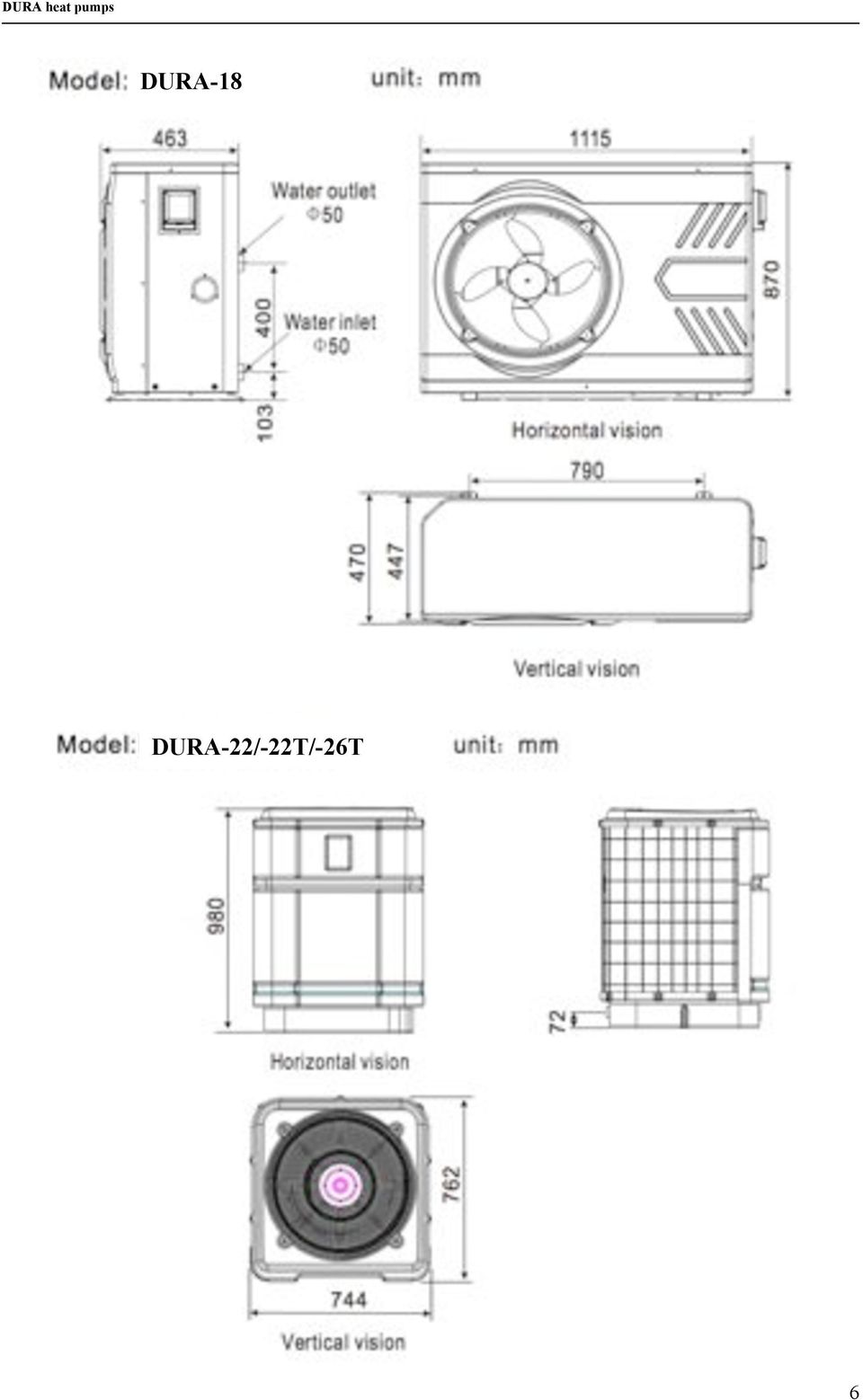
6 DURA-18 DURA-22/-22T/-26T 6
7 3. Installation and connection 3.1 Remarks The factory only provides the heat pump unit; the other parts, including a contingent by-pass, are to be provided by the user or the installer. Attention: Please take the following steps when installing the heat pump: 1. Each addition of chemicals has to be performed through the conduits located AFTER the heat pump. 2. Install a by-pass 3. Always place the heat pump on a solid base and use the supplied silent blocks in order to avoid vibrations and noise. 4. Always keep the heat pump in upright position. If the unit has been tilted, you should wait for at least 24 hours before turning it on. 3.2 Location of the heat pump The unit will perform well on any location provided three factors are present: 1. Fresh air - 2. Electricity - 3. Pool filter piping The unit may be installed virtually anywhere outdoors providing minimum distance requirements are met with respect to other objects (see diagram below). For indoor pools please consult your installer. If the unit is placed in a windy area, no problems occur with e.g. the pilot light, as opposed to what is often the case with gas heaters. ATTENTION: Do not place the unit in an enclosed area with a limited air volume where the unit's discharged air will be re-circulated or near shrubs that could block the air inlet. These locations deny the unit a continuous fresh air supply, which reduces its efficiency and may prevent adequate heat yield. See diagram below for minimum required distances. 7

8 3.3 Distance from the pool Normally, the pool heat pump is installed within a 7.5 meter radius of the pool. The greater the distance from the pool, the greater the heat loss from the piping. Since the piping is buried for the most part, heat loss is minimal for distances of up to 30 meters (15 meters to and from the pump = 30 meters total), unless the soil is wet or the water level is high. Heat loss per 30 meters could roughly be estimated at 0.6 kw-hour (2000 BTU) for every 5 C temperature difference between the pool water and the soil surrounding the pipe, which translates to an operation time increase of 3 to 5 %. 3.4 Installation of the check-valve Attention When using automatic chlorine and ph dosage systems, it is of uttermost importance to protect the heat pump from high concentrations of these chemicals that could corrode the heat exchanger. Therefore, such systems should add the chemicals in the conduits located DOWNSTREAM of the heat pump and it is recommended to install a check-valve in order to prevent backflow when there is no water circulation. Damage to the heat pump caused by disregarding any of these recommendations will invalidate the warranty. 8
 for every 5 C temperature difference between the pool water and the soil surrounding the pipe, which translates to an operation time increase of 3")
9 3.5 Typical setup Note This setup is just an example 3.6 Adjusting the by-pass To!Pool BY#$#PASS Valve!1 Valve!3 Valve!2 From!Pool The heat pump reaches maximum efficiency when temperature difference between IN and OUT is about 1 2 degrees Celsius (see parameters A and B, par 4.3). The temperature difference is influenced by the flow of water through the heat pump. The flow can be adjusted with By-pass valve 1. The flow increases when valve 1 is shut more and vice versa. out Heat!pump in Operating pressure of the refrigerant can be monitored on the pressure gauge of the heat pump. The pressure is infuenced by water- and ambient temperature and is automatically controlled by the heat pump. Note The absence of a by-pass or performing an inadequate by-pass adjustment may cause the heat pump to function less well or may even damage it, which will invalidate the warranty. 9

10 3.7 Electrical hook-up Important - Although the heat pump is electrically isolated from the rest of the unit, this only prevents the passage of electricity to or from the pool water. Grounding the unit is still required to protect yourself from short circuits inside the unit. Make for adequate ground connection. Check if the electrical mains voltage corresponds with the operating voltage of the heat pump prior to hooking up the unit. It is recommended to use a separate fuse (slow type D-curve) as well as adequate wiring (see table below). Connect the electrical wires with the terminal block labelled TO POWER SUPPLY. Next to this connection, there is a second terminal block labelled TO PUMP, to which the filter pump (max. 5A/240V) or an electrical relay for a filtration pump can be connected. This connection makes it possible to control filter pump operation with the heat pump. See further; paragraph 4.2 (parameter 9) for the different possibilities. TO PUMP connection Remark For 3 phase motors (like a compressor), switching 2 phases may cause an inversion in the rotational direction, which could damage the unit. Therefore, a protection device has been built in, which will interrupt the circuit if the connection has not been performed correctly. If, right after electrical connection has been made, the display of the pump does not illuminate, and the pump doesn t start, 2 phase wires have to be switched. Model Voltage (volt) Fuse (A) Nominal current (A) Cable diameter (mm 2 ) (for a max. length of 15 meters) DURA ,8 2 x 2,5 + 2,5 DURA ,7 2* DURA ,4 2*2, DURA ,4 2* DURA ,5 2 x DURA-22T 3 x ,7 4 x 2,5 + 2,5 DURA-26T 3 x ,1 4 x 2,5 + 2,5 10
 as well as adequate wiring (see table below). Connect the electrical wires with the terminal block labelled TO POWER SUPPLY.")
11 3.8 First time start-up Note - In order for the unit to heat the pool (or spa), the filter pump must be running so that the water can circulate through the heat pump. Without this circulation, the heat pump will not start. When all connections have been made and checked, you should follow these steps: 1. Turn on the filter pump. Check for leaks and verify flow to and from the pool. 2. Turn on the electrical power supply to the unit, then press the ON/OFF key on the electronic control panel. The unit should start when the time delay period has lapsed (see further). 3. When the unit has been running for a couple of minutes, check if the air leaving the unit is cooler. 4. Check the performance of the flow switch as follows: with the unit running, turn the filter pump off. The unit should also switch off automatically. If not, the flow switch must be readjusted. (see further under 6.2). 5. Allow the unit and filter pump to run 24 hours a day until the desired pool water temperature is reached. When the set temperature is reached, the unit switches itself off. The unit will now automatically restart (as long as your filter pump is running) when the temperature of the pool water experiences a drop of more than 1 C below the set temperature. Depending on the starting temperature of the pool water and the air temperature, it can take several days for the water to reach the desired temperature. Covering the pool can drastically reduce this period. Water flow switch the unit is equipped with a flow switch that is switched on when enough water is flowing in the unit and that is switched off when the water flow becomes too low (e.g. when the filter pump is switched off). Time delay the unit is equipped with a built-in 3-minute start delay included to protect the compressor and electrical contacts. After this time delay, the unit will automatically be restarted. Even a brief interruption of the power supply will activate the start delay and prevent the unit from starting immediately. Additional interruptions of the power supply during the delay period will have no effect on the 3-minute countdown. 3.9 Condensation When the swimming pool water is being heated by the heat pump, the incoming air is cooled down quite a bit, which can cause condensation on the fins of the evaporator. Condensed volumes can attain several litres per hour under high atmospheric humidity. Sometimes, this is wrongfully interpreted as a water leak. 11
. 3. When the unit has been running for a couple of minutes, check if the air leaving the unit is cooler. 4.")
12 4. Use and operation 4.1 Features of the LED control panel LED screen Press or to modify settings Press MODE to set the operating mode On/Off Access to parameters Set start time Set stop time Press CLOCK to set the time With the On/Off key, the heat pump is turned on or turned off (stand-by status). If the LED next to this key lights up, the heat pump is turned ON. Setting the desired temperature of the swimming pool water is achieved with the arrow keys, regardless if the heat pump is turned ON or OFF. You simply press the arrow keys to set the desired temperature directly. When the unit is turned ON and is running, the temperature of the swimming pool water can be read off the LED screen. When the unit is turned ON and the desired temperature is reached, OFF appears on the LED screen. When the unit is turned OFF, OFF is always displayed on the LED screen; the heat pump goes on monitoring all parameters of the system and all protection systems remain active. The heat pump is thus in STAND-BY mode. We will continue using this expression if we wish to indicate that the heat pump is turned OFF. 12

13 4.2 Setting the parameters Parameters can always be checked by pressing the service key, regardless if the pump is turned ON or is in STAND-BY mode. Only in STAND-BY mode can the parameters be modified. This is an overview of the different parameters and their standard values. The first number on the LED screen stands for the number of the parameter and the second one for its value. Parameter Description Standard 0 Desired temperature in cooling mode (8 28 C) 20 C 1 Desired temperature in heating mode (7 40 C) 27 C 2 Operation time of the compressor before defrosting mode starts (30 90 minutes) 45 min 3 Temperature of evaporator at which defrosting starts (-30 0 C) -7 C 4 Temperature of evaporator at which defrosting stops (2 30 C) 13 C 5 Maximum duration of defrosting procedure (0 12 min) 8 min 6 Mode of electronic expansion valve (0=manual/1=automatic) 1 7 Memory function for automatic start-up (0 for no and 1 for yes ) 1 8 Operating mode (see table below) 2 9 Filter pump control (see table below) 0 10 Fan mode (see below) 1 11 Fan control type (0 for triac control and 1 for voltage control) 1 12 Lowest FAN control 50% 13 Highest FAN control 100% 14 Superheat value 3 15 Expansion valve position at rest 35 Parameters 2 up to and including 5 are the settings for the automatic defrosting mode. They have been set from the factory for optimal operation and very rarely need to be adjusted by a specialized technician, that is, only if conditions demand it. Parameter 7 indicates if the heat pump should or shouldn t start automatically after an interruption of the power supply. Parameter 8 is for adjusting the possible operating modes of the heat pump. Value for parameter 8 Possible modes Can be selected with Mode key 2 Heating only Yes Parameter 9 is for determining how the filter pump should be controlled. If you want to have it controlled by the heat pump, you have to connect the electrical wires of this pump, through a separate relay, to the terminal block labelled TO PUMP that is located next to the one labelled TO POWER SUPPLY. Value for parameter 9 Control 0 The filter pump runs all the time 1 The filter pump runs as long as the compressor is turned ON 2 Intermittent operation: runs for 3 minutes every 30 minutes when compressor has stopped 13
 20 C 1 Desired temperature in heating mode (7 40 C) 27 C 2 Operation time of the compressor before defrosting mode starts")
14 Parameter 10 to 13 set the desired operation mode for the fan speed. On HP series heat pumps, only 1 fan mode is available. For proper operation of the heat pump, the values of these parameters must ALWAYS remain on factory setting. Parameters are modified as follows: Set the heat pump in its STAND-BY mode. Press the service key to access the parameter menu. The parameter number and its value will blink simultaneously. Press the arrow key or to select the desired parameter. Then press MODE and simultaneously. Now, only the value of the parameter will be blinking. Then select the desired setting with the arrow key or. Stop for 5 seconds or press the service key to save the new setting. The LED screen will again display OFF. Only parameters 0 and 1 (depending on the selected mode) are set directly with or 4.3 Checking the status Further down in the parameter menu, after numbers from 0 to 11, you encounter parameters A to E. These cannot be modified. They indicate the values the unit is currently measuring for these parameters. Parameter Measured value A Temperature of in flowing water (-9 99 C) B Temperature of out flowing water (-9 99 C) C Temperature of evaporator (-9 99 C) D Temperature of refrigerant at compressor inlet (-9 99 C) E Ambient temperature (-9 99 C) F Position of expansion valve (0 50 ; N*10) 14

15 4.4 Setting the CLOCK Start setting the clock by pressing the CLOCK key. The LED screen will display the time and the hours will start to blink. Press or to set the desired hour. Press CLOCK again. Now, the minutes start blinking. Press or again to set the minutes. Press CLOCK again to save the settings. While setting the clock, the TIMER ON and TIMER OFF keys are inactive. 4.5 Use of timers Timers allow you to set a time window in which the heat pump will be active. If you want the heat pump to work only during the day, you can for instance set the TIMER ON key to 08:00 and the TIMER OFF key to 20:00. Setting the time can only be achieved when the pump is turned ON. When it is in STAND-BY mode, timers are automatically deactivated Setting TIMER ON The TIMER ON key activates the time at which the heat pump is automatically turned on. Start setup by pressing the TIMER ON key. This displays the previously set time on the LED screen and makes it blink. Press TIMER ON again. Now, only the hours start blinking. Press or to set the desired hour. Press TIMER ON again. Now, the minutes start blinking. Press or again to set the minutes. Press TIMER ON again to save the setting and to activate start time. Deactivation of TIMER ON when the heat pump is turned ON is achieved as follows: Press TIMER ON. The set time appears and starts blinking. Now, press CLOCK to deactivate the timer Setting TIMER OFF The TIMER OFF key activates the time at which the heat pump will automatically stop. Start setup by pressing the TIMER OFF key. This displays the previously set time on the LED screen and makes it blink. Press TIMER OFF again. Now, only the hours start blinking. Press or to set the desired hour. Press TIMER OFF again. Now, the minutes start blinking. Press or again to set the minutes. Press TIMER OFF again to save the setting and to activate stop time. Deactivation of TIMER OFF when the heat pump is turned ON is achieved as follows: Press TIMER OFF. The set time appears and starts blinking. Now, press CLOCK to deactivate the timer. 15

16 5. Protection systems DURA heat pumps are equipped with the following standard protection systems: 5.1 Flow switch Thanks to this flow switch, the heat pump will not work when the filter pump is not working (and the water is not circulating). This system prevents the heat pump from heating only the water present in the heat pump itself. The protection also stops the heat pump if water circulation is cut off or stopped. 5.2 Refrigerant gas high and low pressure protection The high pressure protection makes sure the heat pump is not damaged in case of over-pressurisation of the gas. The low pressure protection emits a signal when refrigerant is escaping from the conduits and the unit cannot be kept running. 5.3 Overheating protection on the compressor This protection protects the compressor from overheating. 5.4 Automatic defrost control When the air is very humid and cold, ice can form on the evaporator. In that event, a thin layer of ice appears that will grow increasingly bigger as long as the heat pump is running. When the temperature of the evaporator has become too low, automatic defrost control will be activated, which will reverse the heat pump cycle so that hot refrigerant gas is sent through the evaporator during a brief period of time to defrost it. 5.5 Temperature difference between inflowing and outflowing water During normal operation of the heat pump, the temperature difference between inflowing and outflowing water will approximate 1 to 2 C. In the event that the pressure switch does not work and that the water stops circulating, the temperature probe monitoring the outflowing water will always detect a rise in temperature. As soon as the temperature difference between inflowing and outflowing water exceeds 13 C, the heat pump will be automatically turned off. 5.6 Low temperature cut-out If, during cooling, the temperature of the outflowing water reaches 5 C or drops below this temperature, the heat pump will turn itself off until the water temperature reaches or exceeds 7 C again. 16

17 5.7 Anti-frost protection during winter This protection can only be activated if the heat pump is in STAND-BY mode First anti-frost protection If the filter pump is controlled by the heat pump (regardless of the value for parameter 9) and when the water temperature lies between 2 and 4 C and the air temperature is lower than 0 C, the filter pump will be automatically turned on to prevent the water from freezing in the piping. This protection is deactivated when the temperature rises again Second anti-frost protection If the water temperature drops even more, that is, below 2 C (during long frost periods), the heat pump will also start running to heat the water until its temperature approximates 3 C. When this temperature is reached, the heat pump will stop, but anti-frost protection will remain active until conditions change. 17
, the heat pump will also start running to heat the water until its temperature")
18 6. Directions 6.1 Swimming pool water chemistry Special attention should be paid to the chemical balance of the pool water. The pool water values should always stay within the following limits: Min. Max. ph Free chlorine (mg/l) TAC (mg/l) Salt (g/l) 8 Important: failure to comply with these limits will invalidate the warranty. Note: exceeding one or several limits can damage the heat pump beyond repair. Always install water treatment equipment past the heat pump s water outlet, especially if the chemicals are automatically added to the water. A check-valve should also be installed between the outlet of the heat pump and this equipment in order to prevent products from flowing back into the heat pump if the filter pump stops. 6.2 Heat pump winterizing Important: failure to take the necessary precautions for winterizing can damage the heat pump, which will invalidate the warranty. The heat pump, filter pump, filter and conduits must be protected in areas where the temperature can drop below the freezing point. Evacuate all water from the heat pump as follows: 1. interrupt the electrical power supply to the heat pump 2. close the water supply to the heat pump: completely close valves 2 and 3 of the by-pass 3. disconnect the water inlet and outlet coupler fittings of the heat pump and let the water drain out of the unit 4. loosely reattach water inlet and outlet coupler fittings to the heat pump in order to prevent dirt from getting into the conduits. Note: these precautions should not be taken if you choose to use the built-in anti-frost protection. 6.3 Restarting the pump after winter If you purged your heat pump for winterizing, you should undertake the following steps to restart it in spring: 1. check first if there is no dirt in the conduits and if there are no structural problems 2. check if the water inlet and outlet coupler fittings are adequately fastened to the heat pump 3. start the filter pump to start the water flow to the heat pump. Set the by-pass again. 4. reconnect the electrical power supply to the heat pump and turn it ON. 18

19 6.4 Check-up DURA heat pumps have been developed and built to last, that is, if they have been installed correctly and can run under normal conditions. Regular check-ups are important if you want your heat pump to function safely and efficiently for years on end. The following directions can help you achieve optimal results: 1. make for easy access to the service panel 2. keep the area surrounding the heat pump free of contingent organic waste 3. prune the vegetation near the heat pump so that there is enough free space around the pump 4. remove contingent water sprinklers from the vicinity of the heat pump. They can damage the heat pump. 5. prevent rain from directly running off a roof onto the heat pump. Install proper drainage. 6. do not use the heat pump if it has been flooded. Immediately contact a qualified technician to inspect the heat pump and repair it if should prove necessary. Condensation can occur when the heat pump is running. This condensation can flow away through an opening in the base pan of the unit. The amount of condensation water will increase when atmospheric humidity is high. Remove any dirt that could possibly hamper the evacuation of condensation. 10 to 20 litres of condensation water can be produced while the unit is running. If more condensation is produced, stop the heat pump and wait for one hour before checking for leaks in the conduits. NOTE: A quick way to verify that the water running through the condensation drain is indeed condensation, is to shut off the unit and keep the pool pump running. If the water stops running out of the condensation drain, it is condensation. AN EVEN QUICKER WAY is to TEST THE DRAIN WATER FOR CHLORINE. If no chlorine is detected, the drain water is a result of condensation. Also take care to leave air inlet and exhaust passages free. Prevent exhaust air from immediately re-entering the unit through the inlet. 19

20 7. Maintenance and inspection 7.1 Maintenance Check the water inlet and drainage often. The water and air inflow into the system should be sufficient so that its performance and reliability does not get compromised. You should clean the pool filter regularly to avoid damage to the unit caused by clogging of the filter. The area around the unit should be spacious and well ventilated. Clean the sides of the heat pump regularly to maintain good heat exchange and to save energy. Check if all processes in the unit are operational and pay special attention to the operation pressure of the refrigerant system. Check the power supply and cable connections regularly. Should the unit begin to function abnormally or should you notice a smell from an electrical component, arrange for timely repair or replacement. Winterizing : make sure to purge all the water from the heat pump and other systems in order to prevent frost damage. You should also purge the water if the unit will not work for an extended period of time. You should check all parts of the unit thoroughly and completely fill the system with water before turning it on again afterwards. 7.2 Troubleshooting guide Improper installation may result in an electrical discharge that could lead to death of or serious injury to pool users, installers or others due to electrical shock and may also cause damage to property. DO NOT attempt to modify the internal configuration of the heat pump. 1. Keep your hands and hair clear of the fan blades to avoid injury. 2. If you are not familiar with your pool filtering system and heat pump: a. Do not attempt to adjust or service without consulting your dealer or your professional pool or air conditioning contractor. b. Read the entire installation and user manual before attempting to use, service or adjust the unit. c. Start the heat pump at least 24 hours after its installation in order to prevent damage to the compressor. Nota: Switch off the power prior to maintenance or repairs. Important remark: if a malfunction cannot be resolved immediately, your installer can contact our customer service. To be able to help you, we will need the serial number of your heat pump. In order to analyse the problem itself, we will need to know the message (error code) that is displayed on the LED screen, as well as the values for the settings (parameters 0 to 15) and for the status of the heat pump (parameters A to F) just before the failure or, if this is impossible, just after it. Please keep this information at hand when calling our customer service. This information is also indispensable if you need to return a heat pump. Returning the unit should occur according to our RMA procedure guidelines. 20

21 On the following pages, you will find an overview of the different types of failure problems that can occur, along with directions to solve them. Problem: the heat pump doesn t work Observation: the screen does not light up and the fan/compressor doesn t make a sound Possible cause Solution No electrical power supply Check power supply (wiring, fuses,...) Problem: the heat pump doesn t work Observation: the screen displays OFF and the LED next to is not lit Possible cause The pump is in stand-by mode Turn on the pump Solution Problem: the heat pump doesn t work Observation: the screen displays OFF and the LED next to is lit Possible cause Solution 1. The set temperature has been reached 1. No action required; all is well 2. The heat pump isn t functioning yet 2. Wait until the start time delay period has lapsed (3 minutes) Problem: the heat pump works but doesn t heat Observation: the compressor is running but the fan isn t and the HEATING/DEFROST LED is blinking Possible cause Solution The defrosting cycle is running No action required; all is well Problem: the heat pump works normally but there is no or insufficient heating Observation: the screen displays the temperature but no error codes Possible cause Solution 1. Insufficient capacity of the heat pump in proportion to the size of the swimming pool Install a larger sized model or an extra heat pump. Cover the pool to limit heat loss 2. The compressor works but the fan doesn t Check the electrical wiring of the fan. Replace the condenser or the fan motor if necessary. 3. The fan works but the compressor doesn t Check the electrical wiring of the compressor. Replace the condenser or the compressor if necessary. 4. The heat pump has not been placed on an optimal location Make for sufficient air circulation (see manual for details) 5. Faulty temperature setting Set the correct temperature 6. By-pass not adjusted Have the by-pass readjusted by the installer 7. Massive ice formation on the evaporator Have the settings for automatic defrost control checked by the installer 8. Not enough refrigerant Have the heat pump checked by a refrigeration technician Problem: the heat pump works normally but the water is cooling down instead of heating up Observation: the screen displays the temperature but no error codes Possible cause Solution The wrong mode has been selected Verify the parameters, select the correct mode The controller is out of order Check the voltage in the electrical wiring to the 4-way valve. If no electric potential is measured, replace the controller The 4-way valve is out of order Check the voltage in the electrical wiring to the 4-way valve. If electric potential is measured, replace the coil. If the problem persists, have the heat pump checked by a refrigeration technician 21
22 Problem: the heat pump works but stops after a short while Observation: the screen displays OFF Possible cause Solution Wrong setting of parameters Check the settings of the parameters and modify if necessary Problem: the heat pump doesn t stop Observation: the screen displays the temperature but no error codes Possible cause Solution Wrong setting of parameters Check the set parameters and adjust them if necessary (settings just above the capacity of the heat pump) Pressure switch out of order Check operation of the pressure switch by turning off the filter pump and restarting it. If the heat pump doesn t react to this, the pressure switch must be adjusted or replaced. Electrical failure Contact your installer Problem: water leak Observation: there s an amount of water under the heat pump Possible cause Solution Condensation due to atmospheric humidity No action required Water leak Try to localize the leak and check for the presence of chlorine in the water. If that is the case, the heat pump must be temporarily replaced during repair. Problem: abnormal amount of ice formed on the evaporator Observation: the evaporator is for the most part covered in ice Possible cause Solution Insufficient air inflow Check the location of the heat pump and remove any dirt that could be present on the evaporator High water temperature If the pool water is already quite hot (warmer than 29 C), the probability of ice formation increases. Lowering the set temperature is a possible option. Incorrect setting of automatic defrost control Check the settings of the defrosting function together with your installer The 4-way valve is out of order Check the voltage in the electrical wiring to the 4- way valve. If electric potential is measured, replace the coil. If the problem persists, have the heat pump checked by a refrigeration technician. Not enough refrigerant Have the heat pump checked by a refrigeration technician. 22
23 7.3 Overview of possible error codes displayed on the screen Go back to chapter 5 Protection systems for more detailed information. The heat pump screen displays one of the following codes: Display Problem Cause Solution PP1 WATER IN sensor out of Sensor open or short-circuited Check or replace the sensor order PP2 WATER OUT sensor out of Sensor open or short-circuited Check or replace the sensor order PP3 PIPE sensor out of order Sensor open or short-circuited Check or replace the sensor PP4 SUCTION sensor out of Sensor open or short-circuited Check or replace the sensor order PP5 AIR sensor out of order Sensor open or short-circuited Check or replace the sensor PP6 Temperature difference Insufficient water flow Check the water flow between WATER IN and WATER OUT is too large Pressure switch out of order Replace the pressure switch PP7 Water temperature too low Insufficient water flow Check the water flow during cool-down Sensor WATER OUT Check or replace the sensor displays an incorrect message PP7 First anti-frost protection active Low temperatures for water No action required and air PP7 Second anti-frost protection Low temperatures for water No action required active and air HP High pressure protection Insufficient water flow Check the water flow Pressure switch out of order Replace the pressure switch Too much refrigerant gas present Have the heat pump checked by a refrigeration technician LP Low pressure protection Not enough refrigerant gas Have the heat pump checked by a refrigeration technician Leak in the cooling conduits Have the heat pump checked by a refrigeration technician FLO Insufficient water flow Insufficient water flow Check the water flow Pressure switch out of order Replace the pressure switch EE5 The temperature difference Insufficient water flow Check the water flow between WATER IN and WATER OUT has been too Pressure switch out of order Replace the pressure switch large 3 times in a row EE8 Communication failure No communication between the digital display and the system controller Check the connection between the screen and the controller. Replace screen and/or controller. 23
24 7.4 Check list for installation ATTENTION / OPGELET / ATTENTION / ACHTUNG 1. Free area / vrije ruimte / espace libre / freier platz 2. Install a by-pass / installeer een by-pass / installez un by-pass / installieren sie eine Überbrückung BYPASS Valve!1 Valve!3 Valve!2 out in Heat pump 3. Electrical connection / elektrische aansluiting / raccordement électrique / elektrischer Anschluss DURA V 10A 2*2,5 + 2,5mm 2 DURA V 16A 2*2,5 + 2,5 mm 2 DURA V 20A 2*2,5 + 2,5 mm 2 DURA V 25A 2*4 + 4 mm 2 DURA V 32A 2*4 + 4 mm 2 DURA-22T 3x 400V 20A 4*2,5 + 2,5 mm 2 DURA-26T 3x 400V 20A 4*2,5 + 2,5 mm 2 Read the installation manual for more detailed instructions Lees aandachtig de instructies in de installatiehandleiding Lisez les instructions dans le manuel d installation Lesen sie die Anweisungen im Installation Handbuch 24
25 8. Detailed specifications 8.1 Electrical diagrams DURA-7 DURA-10 25
26 DURA-13 DURA-18 26
27 DURA-22 DURA-22/26T 27
28 8.2 Refrigeration diagram 28
29 9. Warranty 9.1 Warranty Thank you for purchasing our heat pump. LIMITED WARRANTY We warrant all parts to be free from manufacturing defects in materials and workmanship for a period of two years from the date of retail purchase. This warranty is limited to the first retail purchaser, is not transferable, and does not apply to products that have been moved from their original installation sites. The liability of the Manufacturer shall not exceed the repair or replacement of defective parts and does not include any costs for labour to remove and reinstall the defective part, transportation to or from the factory, and any other materials required to make the repair. This warranty does not cover failures or malfunctions resulting from the following: 1. Failure to properly install, operate or maintain the product in accordance with our published Installation & Instruction Manual provided with the product. 2. The workmanship of any installer of the product. 3. Not maintaining a proper chemical balance in your pool [ph level between 7,0 and 7,8. Total Alkalinity (TA) between 80 to 150 ppm. Free Chlorine between 0,5 1,2mg/l. Total Dissolved Solids (TDS) less than 1200 ppm. Salt maximum 8g/l] 4. Abuse, alteration, accident, fire, flood, lightning, rodents, insects, negligence or acts of Gods. 5. Scaling, freezing or other conditions causing inadequate water circulation. 6. Operating the product at water flow rates outside the published minimum and maximum specifications. 7. Use of non-factory authorized parts or accessories in conjunction with the product. 8. Chemical contamination of combustion air or improper use of sanitizing chemicals, such as introducing sanitizing chemicals upstream of the heater and cleaner hose or through the skimmer. 9. Overheating, incorrect wire runs, improper electrical supply, collateral damage caused by failure of O-rings, DE grids or cartridge elements, or damage caused by running the pump with insufficient quantities of water. LIMITATION OF LIABILITY This is the only warranty given by Manufacturer. No one is authorized to make any other warranties on our behalf. THIS WARRANTY IS IN LIEU OF ALL OTHER WARRANTIES, EXPRESSED OR IMPLIED, INCLUDING BUT NOT LIMITED TO ANY IMPLIED WARRANTY OF FITNESS FOR A PARTICULAR PURPOSE AND MERCHANTABILITY. WE EXPRESSLY DISCLAIM AND EXCLUDE ANY LIABILITY FOR CONSEQUENTIAL, INCIDENTAL, INDIRECT OR PUNITIVE DAMAGES FOR BREACH OF ANY EXPRESSED OR IMPLIED WARRANTY. This warranty gives you specific legal rights, which may vary, by country. WARRANTY CLAIMS For prompt warranty consideration, contact your dealer and provide the following information: proof of purchase, model number, serial number and date of installation. The installer will contact the factory for instructions regarding the claim and to determine the location of the nearest service center. All returned parts must have a Return Material Authorization number to be evaluated under the terms of this warranty. 29
SWIMMING POOL HEAT PUMP UNITS. Installation & Instruction Manual DURATECH - series
 SWIMMING POOL HEAT PUMP UNITS Installation & Instruction Manual DURATECH - series Rev. 2.00 18.11.2009 Contents SWIMMING POOL HEAT PUMP UNITS 1 Contents 2 1. Preface 3 2. Specifications 4 2.1 Technical
HEAT PUMP FOR SWIMMING POOL Installation and Instruction Manual
 HEAT PUMP FOR SWIMMING POOL Installation and Instruction Manual Revision 1.0 12.11.2013 Table of contents Table of contents... 2 1. Preface... 3 2. Specifications... 4 2.1 Performance data... 4 3. Installation
SWIMMING POOL HEAT PUMP (THP 55, THP 100, THP 120, THP 170) INSTALLATION AND USER GUIDE
 INSTALLATION AND USER GUIDE") SWIMMING POOL HEAT PUMP (THP 55, THP 100, THP 120, THP 170) INSTALLATION AND USER GUIDE i Read the instructions Contents I. Package content... 3 II. Performance and properties... 3 III. System design...
SWIMMING POOL HEAT PUMP (THP 55, THP 100, THP 120, THP 170) INSTALLATION AND USER GUIDE i Read the instructions Contents I. Package content... 3 II. Performance and properties... 3 III. System design...
SWIMMING POOL HEAT PUMP Owners Manual
 SWIMMING POOL HEAT PUMP Owners Manual This manual refers to the 17.0kw and 21.0kw models only. The heat pump unit is sold with a 1 year warranty. In addition there is a 2 year parts warranty on the compressor
SWIMMING POOL HEAT PUMP
 SWIMMING POOL HEAT PUMP Installation & User Manual Model HP40B HP50B HP65B Hayward Pool Products Canada, Inc. T: 1-888-238-7665 www.haywardpool.ca CONTENT I. Application 4 II. Features 4 III. Technical
OWNER S Manual PRINTED IN CANADA 10/2009
 OWNER S Manual PRINTED IN CANADA 10/2009 Table of contents Introduction 2 General Safety Instructions 4 Installation Instructions Location 6 Water piping 7 Electrical 7 Bonding 8 Bonding and plumbing
543-0032-00, 943-0032-00. User s Manual
 543-0032-00, 943-0032-00 User s Manual 1 Comfort Alert Diagnostics Faster Service And Improved Accuracy The Comfort Alert diagnostics module is a breakthrough innovation for troubleshooting heat pump and
GLACIER POOL COOLERS, LLC OPERATOR INSTRUCTIONS, INSTALLATION AND SERVICE MANUAL
 GLACIER POOL COOLERS, LLC OPERATOR INSTRUCTIONS, INSTALLATION AND SERVICE MANUAL ALL MODELS GPC 23 THROUGH GPC 280 SERIES PATENT NO: US 7,624,589 B1 GPC 23-280 SERIES MADE IN THE USA GLACIER POOL COOLERS,
Heat Pump Water Heater IOM Manual
 Heat Pump Water Heater IOM Manual Installation Operation & Maintenance This manual is intended as an aid to qualified service personnel for proper installation, operation and maintenance of the heat pump
Heat Pump. Quick Start Guide Models: 035, 055, 075, 090, 115, 110, 120, 121, 135, 155, 156, & 175
 Heat Pump Quick Start Guide Models: 035, 055, 075, 090, 115, 110, 120, 121, 135, 155, 156, & 175 For product manuals and further installation / operation procedures visit www.aquacal.com Important Read
NewAir AC-10100E / AC-10100H Portable Air Conditioner Owner s Manual PLEASE READ AND SAVE THESE INSTRUCTIONS
 NewAir AC-10100E / AC-10100H Portable Air Conditioner Owner s Manual PLEASE READ AND SAVE THESE INSTRUCTIONS ELECTRICAL SAFETY This appliance is for indoor use only. Always turn off the unit and unplug
Air Conditioner Water Heater - A Product of HotSpot Energy LLC
 Air Conditioner Water Heater - A Product of HotSpot Energy LLC PLEASE READ THIS BEFORE YOU INSTALL THE UNIT 1. This air conditioner must be installed and/or repaired by a qualified technician. If you perform
Dealer Sales & Service Guide
 Analog Models w/thermostat or Timerstat Heat Siphon Not Starting 1 BREAKER TRIPPED - Check Breaker Box for correct size breaker Breakers: EX; Domestic model 2.25hp (20amp) 3.25hp (40amp) 5hp (50amp) check
Ceiling Mount Air Handler Manual
 www.surna.com 303.993.5271 Ceiling Mount Air Handler Manual Models: CMAH12, CMAH18, CMAH24, CMAH30, CMAH36, CMAH48, CMAH60 Revised: September 2014 Table of Contents Warranty Information 4 Limited Warranty
DUCT TYPE AIR CONDITIONER
 OPERATING MANUAL OPERATING MANUAL BEDIENUNGSANLEITUNG MODE D EMPLOI MANUAL DE FUNCIONAMIENTO MANUALE DI ISTRUZIONI ΕΓΧΕΙΡΙ ΙΟ ΛΕΙΤΟΥΡΓΙΑΣ MANUAL DE INSTRUÇÕES AIR CONDITIONER DUCT TYPE English Deutsch
SSNICLRG SSNICSM PLNICLRG PLNICSM
 H0284400A Installation Data Installation Manual Jandy Housing for Wet Niche Fixtures For Gunite Pool and Spa Installations - Plastic Model Nos. PLNICLRG and PLNICSM and Stainless Steel Model Nos. SSNICLRG
PANASONIC TROUBLE SHOOTING GUIDE
 A General Guide To Room Style Products Pipework Pipe sizes and lengths should be as the relevant Technical Guide Both lines should be insulated No line accessories or oil traps should be fitted In cooling
USER S MANUAL HSC-24A
 AIRREX AIR CONDITIONER USER S MANUAL HSC-24A Thank you for purchasing an AIRREX AIR CONDITIONER. BEFORE operation please read this user s manual carefully. Keep this manual readily available. It is ESSENTIAL
HEAT PUMP FREQUENTLY ASKED QUESTIONS HEAT PUMP OUTDOOR UNIT ICED-UP DURING COLD WEATHER:
 HEAT PUMP FREQUENTLY ASKED QUESTIONS HEAT PUMP OUTDOOR UNIT ICED-UP DURING COLD WEATHER: It is normal for a heat pump to have a build up of white frost on the outside coil during cold damp weather. The
SERVICE MANUAL. Room Air Conditioner Multi Split Wall-Mounted Type Indoor. FSAI-Pro-91AE2 FSAI-Pro-121AE2 FSAIF-Pro-181AE2
 SERVICE MANUAL Room Air Conditioner Multi Split Wall-Mounted Type Indoor FSAI-Pro-91AE2 FSAI-Pro-121AE2 FSAIF-Pro-181AE2 NOTE: Before servicing the unit, please read this at first. Always contact with
DERON Air/Water Swimming pool Heat Pump. CY/DY series for Heating/Cooling. Description
 Description Compact air/water heat pump for outside installation. With suction gas cooled rotary compressor. With extensive aluminium/cu lamellar tube evaporator and PVC Titanium condenser. Axial fan Refrigerant
NewAir AC-10000E, AC-10000H Portable Air Conditioner Owner s Manual PLEASE READ AND SAVE THESE INSTRUCTIONS
 NewAir AC-10000E, AC-10000H Portable Air Conditioner Owner s Manual PLEASE READ AND SAVE THESE INSTRUCTIONS BEFORE USE GENERAL SAFETY INSTRUCTIONS: ALWAYS OPERATE THE UNIT IN AN UPRIGHT POSITION AND PLACE
Miami Heat Pump HP Series Installation Guide
 CAUTION- THIS UNIT IS FOR INDOOR USE ONLY!! WARNING BEFORE ANY INSTALLATION OR MAINTANCE IS STARTED PLEASE READ COMPLETE INSTLLATION GUIDE. INSTALLATION START-UP AND SERVICE INSTRUCTION- The HP Water Source
POOL SUNSHINE IONIZER MODELS SPD, SPD2 AND SPS INSTALLATION INSTRUCTIONS
 Sunshine Pool Products, LLC Manufacturer of Quality Pool & Spa Products 902 W 2010 S, Syracuse, Utah 84075 USA Voice: 801-825-4523 Website: www.sunshinepool.com Email: info@sunshinepool.com POOL SUNSHINE
Home Owners Guide HR SERIES HEAT RECOVERY VENTILATOR (HRV) Models HR100V, HR160H & HR220H RESIDENTIAL USE ONLY HR160H & HR220H
 Models HR100V, HR160H & HR220H RESIDENTIAL USE ONLY HR160H & HR220H") HR SERIES HEAT RECOVERY VENTILATOR (HRV) Home Owners Guide Models HR100V, HR160H & HR220H RESIDENTIAL USE ONLY HR100V HR160H & HR220H READ AND SAVE THIS GUIDE PP0924 09/2013 ABOUT S&P S&P is the world's
HR SERIES HEAT RECOVERY VENTILATOR (HRV) Home Owners Guide Models HR100V, HR160H & HR220H RESIDENTIAL USE ONLY HR100V HR160H & HR220H READ AND SAVE THIS GUIDE PP0924 09/2013 ABOUT S&P S&P is the world's
OPTIONAL SLENDER REMOTE CONTROL
 DAIKIN ROOM AIR CONDITIONER Operation Manual OPTIONAL SLENDER REMOTE CONTROL BRC944A2B READ BEFORE OPERATION Safety Precautions...2 Names of Functions of Parts...4 Preparation before Operation...5 OPERATION
CARING FOR YOUR WATER HEATER
 http://waterheatertimer.org/troubleshoot-rheem-tankless-water-heater.html Water Heater Inspections CARING FOR YOUR WATER HEATER Venting System (Direct Vent Only) The venting system should be inspected
USER S MANUAL FH052EAV1 FH070EAV1. System Air Conditioner (Cooling and Heating) ENGLISH ESPAÑOL FRANÇAIS ITALIANO PORTUGUÊS DEUTSCH E HNIKA
 ENGLISH ESPAÑOL FRANÇAIS ITALIANO PORTUGUÊS DEUTSCH E HNIKA") USER S MANUAL FH052EAV1 FH070EAV1 E HNIKA PORTUGUÊS ENGLISH ESPAÑOL ITALIANO DEUTSCH FRANÇAIS System Air Conditioner (Cooling and Heating) E S F I P D G DB98-29263A(1) Safety Precautions Register your
USER S MANUAL FH052EAV1 FH070EAV1 E HNIKA PORTUGUÊS ENGLISH ESPAÑOL ITALIANO DEUTSCH FRANÇAIS System Air Conditioner (Cooling and Heating) E S F I P D G DB98-29263A(1) Safety Precautions Register your
Heat Pump Installation, Maintenance and Service Manual
 Heat Pump Installation, Maintenance and Service Manual This booklet is to be carefully read and instructions followed for efficient and trouble free operation of the Accent Swimming Pool Heat Pump 21 Atkinson
Portable Air Conditioner
 Portable Air Conditioner Owner's Manual Model:3 in 1 12,000 Btu/h Series 3 Please read this owner s manual carefully before operation and retain it for future reference. CONTENTS 1. SUMMARY...1 2. PORTABLE
Indoor coil is too warm in cooling mode or too cold in heating mode. Reversing valve or coil thermistor is faulty
 Codes Room Air Conditioner range: Indoor unit alarm s If timer lamp flashes for 1 second on, 1 second off, this indicates pre heating on the coil during heating mode and is not an error. If timer lamp
Portable Air Conditioner. OWNER S MANUAL Read these instructions before use. Model: MF08CESWW. Voltage rating: 115V~60Hz Power rating : 800W
 MODE ALARM Portable Air Conditioner OWNER S MANUAL Read these instructions before use 8 Model: MF08CESWW Voltage rating: 115V~60Hz Power rating : 800W Customer Support : 1-800-474-2147 For product inquiries
Max primary circuit temperature 90ºC Max primary circuit temp. 90ºC Max secondary circuit temperature 45ºC Max secondary circuit temp.
 EGLISH 1 Product description exchanger equipped with an electronic control unit and circulation pump for the primary circuit. All Aqua-Mex variants can be ordered with an interior coil of either titanium
SERIES 12-600 VOLT ELECTRIC INSTANTANEOUS WATER HEATER FOR EMERGENCY SAFTEY EQUIPMENT INSTALLATION AND OWNERS MANUAL REQUIRED MANTENANCE
 Eemax Inc., 353 Christian Street, Oxford, CT 06478 1 E ema X SERIES 12-600 VOLT ELECTRIC INSTANTANEOUS WATER HEATER FOR EMERGENCY SAFTEY EQUIPMENT INSTALLATION AND OWNERS MANUAL REQUIRED MANTENANCE WARNING
Operating Instructions Split System Air Conditioner
 Operating Instructions Split System Air Conditioner Model No. Indoor Unit Type Indoor Unit Type Nominal Capacity 26 36 F2 Low Silhouette Ducted S-26PF2U6 S-36PF2U6 Connectable outdoor unit lineup This
Please read this owner s Manual carefully before operating the unit. - Cooling - Heating - Dehumidifying - Fan
 Please read this owner s Manual carefully before operating the unit. - Cooling - Heating - Dehumidifying - Fan TABLE OF CONTENTS INTRODUCTION 2 IMPORTANT SAFEGUARDS...2 PACKAGE CONTAINS..2 NAMES OF PARTS.3
Portable Air Conditioner. OWNER S MANUAL Read these instructions before use. Model: MM14CHCSCS
 Portable Air Conditioner OWNER S MANUAL Read these instructions before use Model: MM14CHCSCS Voltage rating: 120V~60Hz Power rating : 1400W(Cooling) Power rating : 1350W(Heating) Customer Support : 1-800-474-21477
Meaco 30L and Meaco 40L dehumidifier instruction manual
 Meaco 30L and Meaco 40L dehumidifier instruction manual Please read this instruction manual before using the dehumidifier and keep safe for future reference SAFETY INSTRUCTIONS PLEASE READ ALL INSTRUCTIONS
INSTALLER S & OWNER S MANUAL
 INSTALLER S & OWNER S MANUAL HVAC INSTALLER: PLEASE LEAVE MANUAL FOR HOMEOWNER DEH 3000 DEH 3000 Part No. 4028539 Dehumidifier & Ventilation System Controller P.O. Box 8680 Madison, WI 53708 TOLL-FREE
Portable Air Conditioner. OWNER S MANUAL Read these instructions before use. Model: MM14CCS. Voltage rating: 115V~60Hz Power rating : 1400W
 Portable Air Conditioner OWNER S MANUAL Read these instructions before use Model: MM14CCS Customer Support : 1-800-474-2147 Voltage rating: 115V~60Hz Power rating : 1400W For product inquiries or support
SERVICE INSTRUCTION R410A. WALL MOUNTEDtype INVERTER SPLIT TYPE ROOM AIR CONDITIONER. Models Indoor unit Outdoor unit
 SERVICE INSTRUCTION SPLIT TYPE ROOM AIR CONDITIONER WALL MOUNTEDtype INVERTER Models Indoor unit Outdoor unit ASYG07LECA ASYG09LECA ASYG12LECA ASYG14LECA AOYG07LEC AOYG09LEC AOYG12LEC AOYG14LEC R410A CONTENTS
Failure code manual. content
 Failure code manual content 一 wall split AC series 2 二 floor standing AC series. 4 三 portable AC series.. 5 四 dehumidifer 6 五 DC inverter single split series...7 六 DC inverter multi-split series 10 1 一
Portable Air Conditioner. OWNER S MANUAL Read these instructions before use. Model: MN12CES / MN10CESWW
 Portable Air Conditioner OWNER S MANUAL Read these instructions before use 8 Model: MN12CES / MN10CESWW Voltage rating: 120V~60Hz Power rating : 1100W (MN12CES) Power rating : 900W (MN10CESWW) Customer
ROOFTOP - HEAT PUMP UNIT. This document applies when installing into an air handler or as part of an air handling system.
 ROOFTOP - HEAT PUMP UNIT Technical data Applies to Model YNRA R410A This document applies when installing into an air handler or as part of an air handling system. CONTENTS 1. General description... 2
Operating Instructions Air Conditioner
 P07-T10130 Operating Instructions Air Conditioner Indoor Unit CS-F24DD1E5 CS-F28DD1E5 CS-F34DD1E5 CS-F43DD1E5 CS-F50DD1E5 Outdoor Unit Inverter Model (HBE5 Series) CU-YL24HBE5 CU-YL28HBE5 CU-YL34HBE5 CU-YL43HBE5
Owner s Manual RBC-AMS41E. Remote controller with weekly timer. Owner s Manual
 Owner s Manual Remote controller with weekly timer RBC-AMS41E Owner s Manual Remote controller Mode d emploi Télécommande Bedienungsanleitung Fernbedienung Manuale di istruzioni Telecomando Manual del
14. Troubleshooting Guide
 14. Guide 14.1 Refrigeration Cycle System In order to diagnose malfunctions, ensure the air conditioner is free from electrical problems before inspecting the refrigeration cycle. Such problems include
User s Guide. Oreck Air Purifier with HEPA Filtration. Important! Read this manual carefully, and keep for future reference.
 User s Guide Oreck Air Purifier with HEPA Filtration Important! Read this manual carefully, and keep for future reference. Enjoy Congratulations on your purchase of the Oreck Air Purifier with HEPA Filtration.
WMSLW / WMBLWH Series Hydronic Upflow/Horizontal Left or Right, Heating and Cooling Air Handler
 WMSLW / WMBLWH Series Hydronic Upflow/Horizontal Left or Right, Heating and Cooling Air Handler Installation Operation Maintenance The WMSLW/WMBLW series is designed for installation in a closet, utility
Table V. Troubleshooting Checklist for Refrigeration Systems. Air or non-condensable gas in system. Inlet water warm.
 Table V Troubleshooting Checklist for Refrigeration Systems TROUBLE POSSIBLE CAUSE CORRECTIVE MEASURE High condensing pressure. Low condensing pressure. Air or non-condensable gas in system. Inlet water
Overheating limit control
 Pahlén electric heater Maxi Heat with digital control is a compact and effective heater for swimming pools. It consists of a glassfibre reinforced polypropylene tank containing resistance-type heating
SECTION 15750 PACKAGED ROOFTOP AIR CONDITIONING UNITS
 SECTION 15750 PART 1 - GENERAL 1.01 DESCRIPTION A. Section includes requirements for roof mounted, self-contained units, with electric cooling, and electric or reverse refrigeration cycle (heat pump) heating
LOBOY 16 AIR CONDITIONERS
 INSTRUCTION MANUAL FOR: LOBOY 16 AIR CONDITIONERS McLean Midwest Corp. dba: McLean Cooling Technology 11611 Business Park Blvd. N Champlin, MN 55316 Tel: 763-323-8200 Fax: 763-576-3200 www.mcleancoolingtech.com
HP switch LP switch Discharge thermo Comp. Surface thermo
 1 Specifications Zubadan Model Name PUHZ-SHW80VHA PUHZ-SHW11VHA PUHZ-SHW11YHA Power supply (phase, cycle, voltage) 1φ, V, Hz 1φ, V, Hz 3φ, 0V, Hz Max. current A 9.5 35.0 13.0 Breaker size A 3 16 Outer
Service manual. Website: www.andico.com.au CAUTION - BEFORE SERVICING THE UNIT, READ THE SAFETY - PRECAUTIONS IN THIS MANUAL.
 Website: www.andico.com.au Service manual CAUTION - BEFORE SERVICING THE UNIT, READ THE SAFETY - PRECAUTIONS IN THIS MANUAL. - ONLY FOR AUTHORISED SERVICE PERSONNEL. MODELS: MPK1-09CR-QB8 MPK1-12ER-QB6
MP-4000 Alarm List (Software version 2.4.3 or later)
") Service Bulletin SUBJECT: MP4000 Alarm s BULLETIN: C 100 DATE: June 19, 2013 ALARM LIST Where it is possible the alarm number is kept the same as for MP-3000. MP-3000 holds alarm number from 0 to 127.
Service Bulletin SUBJECT: MP4000 Alarm s BULLETIN: C 100 DATE: June 19, 2013 ALARM LIST Where it is possible the alarm number is kept the same as for MP-3000. MP-3000 holds alarm number from 0 to 127.
TECHNICAL DATA & SERVICE MANUAL SPLIT SYSTEM AIR CONDITIONER INDOOR UNIT: AW52AL AW64AL AW52AL 387030095 AW64AL 0.8180.463.0 07/05
 TECHNICAL DATA & SERVICE MANUAL INDOOR UNIT: AW52AL AW64AL SPLIT SYSTEM AIR CONDITIONER Model No. Product Code No. AW52AL 387030095 AW64AL 387030096 0.8180.463.0 07/05 IMPORTANT! Please read before installation
Installation Manual DIAPHRAGM WELL TANK
 Installation Manual DIAPHRAGM WELL TANK IN-LINE SERIES: 2-5 & 7 GALLON VERTICAL SERIES: 14-20-25-32-36-52-65-86-96-119 GALLON HORIZONTAL SERIES: 7-14 & 20 GALLON NO LEAD NO LEAD: The weighted average of
york air-conditioning products Residential & VRF News 2015
 york air-conditioning products Residential & VRF News 2015 york air-conditioning products Catalogue Content Split Systems Pag. High wall High Efficiency Inverter YWHJZH 09 to 24 K 6 High wall Inverter
SERVICE INSTRUCTION R410A. WALL MOUNTEDtype SPLIT TYPE ROOM AIR CONDITIONER INVERTER. Models Indoor unit Outdoor unit AOU 9RLFW AOU12RLFW AOU15RLS
 SERVICE INSTRUCTION SPLIT TYPE ROOM AIR CONDITIONER WALL MOUNTEDtype INVERTER Models Indoor unit Outdoor unit ASU 9RLF ASURLF ASU5RLS AOU 9RLFW AOURLFW AOU5RLS R40A CONTENTS. DESCRIPTION OF EACH CONTROL
ACW200C / ACW200CH. Innovative AutoDrain Technology. Owner s Manual Portable Air Conditioner with Heat
 Owner s Manual Portable Air Conditioner with Heat ACW200C / ACW200CH It is important that you read these instructions before using your new purchase and we strongly recommend that you keep them in a safe
Refrigerant Charging Unit ICOGD. 020AH1000 Operating Manual. FR.8.2.4-09 İ-COLD 12.03.2014 Rev. 00
 E Refrigerant Charging Unit ICOGD 020AH1000 Operating Manual FR.8.2.4-09 İ-COLD 12.03.2014 Rev. 00 Contents Technical Specifications... 20 Safety... 21 A/C System... 22 Components... 23 Control Panel...
USER S MANUAL. Duct Type Series. Free Joint Multi Air Conditioner (Cooling and Heating) FUEA Series E S F I P D G DB98-29565A(1) ENGLISH ESPAÑOL
 FUEA Series E S F I P D G DB98-29565A(1) ENGLISH ESPAÑOL") USER S MANUAL Duct Type Series MH MH FEEA Series FUEA Series ENGLISH ESPAÑOL PORTUGUÊS E HNIKA DEUTSCH ITALIANO FRANÇAIS Free Joint Multi Air Conditioner (Cooling and Heating) E S F I P D G DB98-29565A(1)
USER S MANUAL Duct Type Series MH MH FEEA Series FUEA Series ENGLISH ESPAÑOL PORTUGUÊS E HNIKA DEUTSCH ITALIANO FRANÇAIS Free Joint Multi Air Conditioner (Cooling and Heating) E S F I P D G DB98-29565A(1)
INNOVATIVE SOLUTION OF DOMESTIC HEATING SPLIT TYPE SPLIT DHW INTEGRATED TYPE MONOBLOC TYPE
 INNOVATIVE SOLUTION OF DOMESTIC HEATING SPLIT TYPE SPLIT DHW INTEGRATED TYPE MONOBLOC TYPE Fujitsu General realizes considerable energy saving operations by the Heat pump heating system using the ambient
Split Type Room Air Conditioner. KSWM units
 OWNER S MANUAL Split Type Room Air Conditioner KSWM units Please read the operating instructions and safety precautions carefully and thoroughly before installing and operating your room air conditioner.
Hot Water. Heat pump water heaters. Residential and Commercial R410a
 Hot Water Heat pump water heaters Residential and Commercial R410a Heat pump technology Heat Pump Water Heating is a new idea using existing technology and is viewed as the latest generation of water heating
AIR CONDITIONER Duct Type OPERATING MANUAL
 AIR CONDITIONER Duct Type OPERATING MANUAL KEEP THIS MANUAL FOR FUTURE REFERENCE P/N9374379460 CONTENTS SAFETY PRECAUTIONS... 1 FEATURES AND FUNCTIONS... 3 NAME OF PARTS... 4 PREPARATORY OPERATION... 5
G & F Manufacturing Swimming Pool Heat Pump
 G & F Manufacturing Swimming Pool Heat Pump Owner s Installation & Operations Manual 5005001B Version 2.02 TABLE OF CONTENTS Page 2 Introduction 3 Installation 5 Location 5 Wind Tie Down 5 Water Plumbing
Indirect-Fired Storage Water Heater Models WH-30 through WH-80 INSTALLATION AND OPERATING INSTRUCTIONS
 Indirect-Fired Storage Water Heater Models WH-30 through WH-80 INSTALLATION AND OPERATING INSTRUCTIONS Contents Page Ratings and Specifications..................... 2 Installation Requirements......................
Name of Equipment Silver King Model SKMCD1P/C1. This equipment chapter is to be inserted in the appropriate section of the Equipment Manual.
 Name of Equipment Silver King Model SKMCD1P/C1 This equipment chapter is to be inserted in the appropriate section of the Equipment Manual. Manufactured exclusively for McDonald s By Silver King Refrigeration,
Water Priming Mode Purge air from plumbing system. How do I solve ER-3 WATER PRIME: TIPS ON FILLING SPA IMPORTANT NOTE WARNING
 Water Priming Mode Purge air from plumbing system TIPS ON FILLING SPA Before filling remove spa skirt and be sure that all valves in the plumbing system are fully open to maximise the amount of air that
Oil and Coolant Circulating Heating System. Model - OCSM
 Oil and Coolant Circulating Heating System Model - OCSM Installation & Operation Manual 216280-000 REV 2 Identifying Your System The HOTSTART heating system is designed to heat fluids for use in marine
SMM. Installation Operation Maintenance
 SMM Configuration SMM Module for Scroll Units, H Generation Installation Operation Maintenance 1 0 L80 IM 022 GB SMM Configuration SMM Module for Scroll Units, H generation Foreword These installation,
SECTION 23 81 03 - PACKAGED ROOFTOP AIR CONDITIONING UNITS NON-CUSTOM
 SECTION 23 81 03 - PACKAGED ROOFTOP AIR CONDITIONING UNITS NON-CUSTOM PART 1 - GENERAL 1.1 SUMMARY A. Section Includes: 1. Packaged rooftop air conditioning unit (5 tons and smaller). 2. Roof curb. 1.2
AIR-CONDITIONER SPLIT TYPE
 FILE NO. A08-016 SERVICE MANUAL AIR-CONDITIONER SPLIT TYPE RAS-M10PKVP-E, RAS-M13PKVP-E, RAS-M16PKVP-E, RAS-M18PKVP-E / RAS-M10PKVP-ND, RAS-M13PKVP-ND, RAS-M16PKVP-ND, RAS-M18PKVP-ND / RAS-3M26GAV-E1,
INSTANT HOT WATER RECIRCULATING SYSTEM
 INSTANT HOT WATER RECIRCULATING SYSTEM INSTALLATION AND OPERATING INSTRUCTIONS Save manual for future reference MODEL 500800 Warning Please read carefully before proceeding with installation. Your failure
EXTENDED 10 YEAR LIMITED LIFETIME WARRANTY LIMITED LIFETIME WARRANTY
 EXTENDED 10 YEAR LIMITED LIFETIME WARRANTY Spectrum Manufacturing warrants that the heat pumps and air handling equipment (if purchased with a Water to Water System) manufactured by Spectrum Manufacturing
PORTABLE AIR CONDITIONER
 PORTABLE AIR CONDITIONER MAC 7500 Owner s Manual Air Conditioner Dehumidifier Oscillating Fan Please read this owner s manual carefully before operating the unit. POWERED BY 66126113.p65 17 INTRODUCTION
AGS. Owner's Manual. Xantrex Automatic Generator Start Control System
 AGS Owner's Manual Xantrex Automatic Generator Start Control System TABLE OF CONTENTS INTRODUCTION...3 Main Features...3 Safety Summary...3 THINGS YOU SHOULD KNOW...4 THEORY OF OPERATION...5 System...5
LS1024B / LS2024B/ LS3024B. Solar Charge Controller USER MANUAL
 EPSOLAR LS1024B / LS2024B/ LS3024B Solar Charge Controller USER MANUAL Thank you very much for selecting our product! This manual offers important information and suggestions with respect to installation,
Condensing unit type EPSILON-ECHOS LE Technical information manual
 Condensing unit type EPSILON-ECHOS LE Technical information manual 2 > EPSILON ECHOS Water chiller > EPSILON ECHOS /HP Reversible heat pump > EPSILON ECHOS /ST Water chiller with storage tank and pumps
Transport Air Conditioning TRANSPORT AIR CONDITIONING OPERATOR S MANUAL. for SPLIT SYSTEM. Bus Air Conditioning Units.
 R Transport Air Conditioning TRANSPORT AIR CONDITIONING OPERATOR S MANUAL for SPLIT SYSTEM Bus Air Conditioning Units T--326 Rev -- OPERATOR S MANUAL BUS AIR CONDITIONING UNITS GEN IV & GEN V CONTENTS
ITC-BTTN Cellular Bluetooth Gateway. Owner s Manual 1
 ITC-BTTN Cellular Bluetooth Gateway Owner s Manual 1 2 Table of Contents Introduction...3 Package Contents...3 XLink Connections Diagram...4 Setup...5 Pairing your Bluetooth Cell Phone to the XLink...6
Heat Pumps for Swimming Pools
 Page 1 of 5 Heat Pumps for Swimming Pools This factsheet provides members with invaluable information about heat pumps and their use for heating swimming pool water. There is a consumer factsheet already
CONTENTS 1. IMPORTANT NOTICE 2 2. TECHNICAL SPECIFICATION 3 3. OPERATION DETAILS 4 4. ELECTRICAL SCHEMATIC DIAGRAM 13 5. EXPLOSION VIEW 16 6
 TCL WALL MOUNTED SPLIT-TYPE AIR CONDITIONERS SERVICE MANUAL No.TE080528 Models KFTHP-12 KFTHP-18 KFTHP-24 CONTENTS 1. IMPORTANT NOTICE 2 2. TECHNICAL SPECIFICATION 3 3. OPERATION DETAILS 4 4. ELECTRICAL
Why is my air conditioner dripping on my customers?
 De-Mystifying HVAC Why is my air conditioner dripping on my customers? By Ron Prager One of the most frequent emergency service requests is a call for an air conditioner leaking water into the store. These
HEAT SIPHON ANSWERBOOK
 ERROR CODES -Displayed on Player Board There are three different types of error codes displayed by the Digital Player Controller" 1 WARNING CODE - The Warning Code is displayed for the duration the error
ECOCIAT. Domestic hot water heat recovery unit
 Heat recovery unit Domestic hot water High energy efficiency with R410A Compact and quiet Scroll compressors Brazed-plate heat exchangers Heating Heat recovery ENVIRONMENTALLY HFC R410A PROTECTION DE FRIENDLY
Astral Pool Heat Pump
 Astral Pool Heat Pump INSTALLATION AND OPERATING INSTRUCTIONS OUTDOOR INSTALLATION ONLY AstralPool Australia Pty. Limited. A.B.N. 97 007 284 504 Melbourne: Ph: (03) 8796 8600 Fax: (03) 8796 8670 Sydney:
Table Z. Troubleshooting Chart for Air Conditioners. Cause
 Troubleshooting Chart for Air Conditioners Type of Unit Complaint Cause With open-type compressor Electric motor will not start Power failure Check circuit for power source Compressor stuck Locate cause
Model 800 Residential Steam Humidifier Owner s Manual. Includes Safety & Operating Instructions and Warranty Information
 Steam Humidifier Model 800 Residential Steam Humidifier Owner s Manual Includes Safety & Operating Instructions and Warranty Information READ AND SAVE THESE INSTRUCTIONS TABLE OF CONTENTS Safety Cautions...
HEATING OF DOMESTIC OUTDOOR SWIMMING POOLS
 HEATING OF DOMESTIC OUTDOOR SWIMMING POOLS INTRODUCTION 1. There are no general EU regulations and standards for outdoor swimming pool heating. Local regulations in the member countries are covering most
Single Zone LCD Thermostat Operating Instructions
 Fan Cool Furnace *Heat Pump or Heat Strip On/Off F Single Zone LCD Thermostat Operating Instructions MODEL 3313192.XXX Cool/Furnace 3313193.XXX Cool/Furnace/Heat Pump 3313194.XXX Cool/Furnace/Heat Strip
Aerona Air Source Heat Pumps
 ADDENDUM to INSTALLATION INSTRUCTIONS for Aerona Air Source Heat Pumps DOC.87-05/05 Rev.04 March 2013 ATTENTION INSTALLERS - UPDATED INFORMATION! Your Grant Aerona Air Source Heat Pump has a number of
TABLE 1: Wiring Terminals. Connect to... 1C 1H 2C 2H 1H1C 2H1C 2H2C 3H2C
 Installation TURN OFF POWER TO THE SYSTEM AT THE MAIN POWER PANEL TO AVOID ELECTRICAL SHOCK. Installation should be carried out by an electrician or a qualified technician. 1.1 Find a Location for the
FT-100 Fire Training Fog Machine User Manual English
 FT-100 Fire Training Fog Machine User Manual English 2015 Antari Lighting and Effects Ltd. User Manual - English Safety Information Please read the following safety information carefully before operating
Mold Alert... Operation Manual P0270
 Mold Alert... Operation Manual P0270 introduction Congratulations on your purchase of the P0270 Mold Alert! Mold is as old as the Earth and it s everywhere. Under the right set of conditions, it can actually
REMOTE CONTROL MANUAL
 REMOTE CONTROL MANUAL ENGLISH CONTENT PRECAUTIONS...1-2 USING THE REMOTE CONTROL UNIT...3 OPERATION...4-9 Thank you for purchasing our Room Air Conditioner. Before using your air-conditioner, please read
Service & Parts Manual
 Service & Parts Manual Portable Air Conditioner Models P09B and P2B ( Serial Number Beginning with an "A") Models P09B-A and P2B-A Portable Air conditioner-200 Svc Parts (4-200) Service Points and Flow
R22. K Control. Indoor Unit. Nomenclature. Compatibility PL H 3 G K H B. Unit style Heat Pump Horse Power
 R22. K Control. Indoor Unit. Nomenclature. PL H 3 G K H B Compatibility Unit style Heat Pump Horse Power Control Boost Heaters R22. K Control. Outdoor Unit. Nomenclature. PU H 3 Y K A Compatibility Outdoor