Universal Telephone Interface UTI1 Model
|
|
|
- Leo Bell
- 8 years ago
- Views:
Transcription
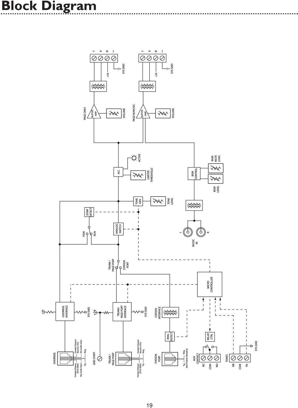
1 Universal Telephone Interface UTI1 Model Addendum to the Installation and Use Manual The following corrections to the UTI1 manual, part number A, are highlighted in bold and underlined. Trunk Disconnect (page 7) The trunk disconnect feature is disabled by default and can be enabled. (Refer to System Programming.) Override Input (page 10) Maximum contact closure resistance is 1000 ohms. Open collector type outputs for controlling a page may also be used. The Override feature includes a quad beep pre-announce tone that can be enabled or disabled. (The default is enabled.) NOTE: SYS GND has been added to the line drawing on page 10 next to Dry Audio Input. Override Tone (page 13) This tone is produced when override is activated. It produces a quad beep pre-announce tone that can be enabled or disabled. (The default is enabled). See System Programming to disable the tone. Feature Codes & Defaults Feature Feature Code Data Default Override Tone Disable Enable Trunk Disconnect Disable Enable Block Diagram NOTE: SYS GND has been added to the block diagram next to Dry Audio Input Bogen Communications, Inc. All rights reserved. Specifications subject to change without notice A Spring Street, Ramsey, NJ 07446, U.S.A. Tel , Fax: ,

2 Universal Telephone Interface UTI1 Model Installation and Use Manual 2004 Bogen Communications, Inc. All rights reserved. Specifications subject to change without notice A 0406

3 2004 Bogen Communications, Inc. All Rights Reserved. Printed in Taiwan. Notice Every effort was made to ensure that the information in this manual was complete and accurate at the time of printing. However, information is subject to change. FCC Statement (Part 15) - Radio Frequency Interference The Universal Telephone Interface (UTI1) generates and uses radio frequency energy and if not installed and used in strict accordance with the manufacturer's instructions, may cause interference to radio and television reception. Testing is being conducted for compliance with the limits for a Class B device in accordance with the specifications in Part 15 of the FCC Rules and Canadian D.O.C. regulations. This testing is designed to provide reasonable protection against such interference. However, there is no guarantee that interference will not occur in a particular installation. If this equipment does cause interference to radio or television reception, which can be determined by turning the UTI1 unit off and on, the user is encouraged to try to correct the interference by one or more of the following measures: - Reorient the radio or TV receiving antenna. - Relocate the UTI1 unit with respect to the radio or TV receiver or vice versa. - Plug the UTI1 unit into a different outlet so that it and the radio or TV receiver are on different branch circuits. If necessary, the user should consult the dealer or an experienced radio/television technician for additional suggestions.the user may find the following booklet, "How To Identify and Resolve Radio-TV Interference Problems," helpful. This booklet was prepared by the Federal Communications Commission (FCC) and is available from the U.S. Government Printing Office,Washington, DC Stock order No Federal Communications Commission (FCC) Statement (Part 68) This equipment is component registered with the Federal Communications Commission (FCC) in accordance with Part 68 of its rules. In compliance with the rules, be advised of the following: Registered equipment may not be used with Coin Telephone Lines. Equipment may be used with Party Lines in areas where state tariffs permit such connections and when equipment is adaptable for such service. This equipment is registered as follows: Registration Number - CD2PA14BUT11 Ringer Equivalence - 1.4B If trouble is experienced, the equipment should be disconnected from the interface to determine if this equipment, or the telephone line, is the trouble source. If the equipment is determined to be malfunctioning, it should not be reconnected until repairs are effected. Repairs to this equipment, other than routine repairs, can be made only by the manufacturer or its authorized agents. If the equipment causes harm to the telephone network, the local telephone company may temporarily discontinue your service and, if possible, notify you in advance. If advance notice is not practical, you will be notified as soon as possible.you will be given the opportunity to correct the problem and informed of your right to file a complaint with the FCC. The local telephone company may make changes in its facilities, operations, or procedures that could affect the proper functioning of your equipment. If they do, you will be given adequate notice in writing to allow you an opportunity to maintain uninterrupted telephone service. Important Safety Information Always follow these basic safety precautions when installing and using the system: 1. Read and understand all instructions. 2. Follow all warnings and instructions marked on the product. 3. DO NOT block or cover the ventilation slots and openings. They prevent the product from overheating. DO NOT place the product in a separate enclosure or cabinet, unless proper ventilation is provided. 4. Never spill liquid on the product or drop objects into the ventilation slots and openings. Doing so may result in serious damage to the components. 5. Repair or service must be performed by a factory authorized repair facility. 6. The product is provided with a UL-CSA approved, 3-wire ground type plug. This is a safety feature. DO NOT defeat the safety purpose of the grounding type plug. DO NOT staple or otherwise attach the AC power supply cord to building surfaces. 7. DO NOT use the product near water or in a wet or damp place (such as a wet basement). 8. DO NOT use extension cords. The product must be installed within 6 feet of a grounded outlet receptacle. 9. DO NOT install telephone wiring during a lightning storm. 10.DO NOT install telephone jacks in a wet location unless the jack is specifically designed for wet locations. 11. Never touch uninsulated wires or terminals, unless the line has been disconnected at the paging or controller interface. 12. Use caution when installing or modifying paging or control lines.

4 Contents UTI1 Feature Callouts...4 Introduction...5 Voice Channel...5 Background Music...5 Signaling Tones...5 Other Features...5 Package Contents...5 Installation...6 Wall Mounting...6 Telephone Interface Wiring Connections & Setup Telephone System Connections...7 Trunk Disconnect...7 PBX Loop Start Trunk Port...7 PBX Ground Start Trunk Port...8 PBX Page Port Contact...8 PBX Page Port VOX...9 PBX Analog Station Port...9 Override Input...10 Other Connections...11 Night Ringer...11 Tone Trigger...11 Paging Output Connections...11 Background Music Input...11 Aux Contacts...11 Controls...12 Paging Level...12 Music Level...12 Music Mute Level...12 Tone Level...12 Limiter Threshold...12 Tones...13 Pre-Announce/Confirmation Tone...13 Tone Trigger...13 Override Tone...13 Setup Tone...13 Reference...13 How to Page...13 Priority Levels...13 System Programming Default Timer...14 VOX Timer...14 DTMF Block...14 Setup Tone...14 Reset Default Values...14 AUX Relay Contact...15 Feature Codes and Defaults...17 Specifications...18 Block Diagram...19 Limited Warranty

5 UTI1 Feature Callouts 1. Power Indicator - Illuminates when AC power has been applied to the unit. 2. AUX Contact Terminals - Provide connections for normally open and normally closed contact closures.the contact closure can be programmed to activate during paging, night ring, tone, override, or any combination (refer to System Programming). 3. Ground Start Terminal - Connection for PBX ground. Used only when the ground start interface is selected. 4. Tone Terminals / Tone Level Control - Terminals provide connections to night ring and tone trigger inputs.tone Level Control sets the level of all tones produced by the system. 5. Override - Secondary paging input with higher priority than TRUNK/PAGE PORT or STATION mode inputs. Connects to either loop start trunk or dry audio signal with contact closure. 6. Trunk/Page Port - Primary paging interface to telephone system when UTI1 is set to trunk or page port mode type interface. 7. Interface Type Slide Switches - Sets telephone interface type for the UTI1. 8. Station Port - Primary paging interface to telephone switch when UTI1 is set to station mode type interface. 9. Limiter Threshold / Limiter Active LED - Control and indicator for output limiter function. 10. Music Input Jacks - Stereo summing input for background music source. 11. Page & Music Terminals - Provides connections to the paging system (background music and voice paging) and the 24V DC power supply. 12. Page Only Terminals - Provides connections to the paging system (voice page only - no music) and the 24V DC power supply. 13. Program/Run Switch & LED - Used to switch unit to program mode.the LED will light when unit is in PROGRAM mode. 14. Music Level Control - Music Level sets background music level. 15. Music Mute Control - Music Mute sets music mute level during paging. 16. Page & Music Level Control - Page & Music Level controls the level of page & music output. 17. Page Only Level Control - Page Only Level controls the level of page only output. 4

6 Introduction The UTI1 Paging System is a paging and signaling system.the system provides the following features and functions: Voice Channel Single-zone paging Telephone interfaces: - loop start trunk - ground start trunk - station access (analog ring-up) - page port contact closure activation - page port voice activation Override paging (using loop start trunk or page port contact closure activation) Two audio outputs (both with level controls): - paging and background music - paging only Each output can provide audio for 150 Bogen one-way amplified speakers, also compatible with 70V amp inputs Pre-Announce/Confirmation Tone Adjustable Automatic Level Control with threshold and active indicator Background Music High impedance transformer isolated BGM input with volume control Variable music mute Signaling Tones Night Ringer (contact closure activation) Tone Trigger (tone and duration selectable, closure-activated) Other Features C-form contact set with programmable activation events Non-volatile memory for setup data (no backup battery required) Setup Tone to assist in volume setting, etc. Pluggable terminal strips Microcontroller-based operation DTMF setting of operating parameters Package Contents (1) UTI1 (1) Installation and Use Manual 5

7 Installation Wall Mounting Mounting to a plywood backboard or studs: 1. Hold the unit level against the surface to which it will be mounted. 2. Mark where the mounting screws should be positioned. 3. Set the unit aside and install the screws leaving about 1 /4" of the screws sticking out of the surface. 4. Slip the unit over the screws and tighten them snugly. 6

8 Telephone Interface Wiring Connections & Setup Telephone System Connections The UTI1 connects to virtually any telephone system: PBX station lines and CO lines, PBX loop start trunk ports, PBX ground start trunk ports, and page ports. Interface installation consists of setting the slide switches and connecting with modular (RJ11) telephone plugs. Refer to the appropriate procedure in this section to connect the UTI1 to the telephone system. Note: In all cases, make sure that power to the UTI1 is disconnected before performing the installation. Trunk Disconnect The UTI1 includes a trunk disconnect feature. The purpose of the trunk disconnect feature is to release the UTI1 from the trunk port in the event a user does not hang up the phone properly after making a page. If the UTI1 does not detect voice for the interface VOX time-out period, or if the interface default timer expires, the UTI1 will attempt to release from the trunk. When using the trunk disconnect feature with a trunk interface, the PBX must have disconnect supervision available on the trunk port connected to the UTI1. The trunk disconnect feature is enabled by default and can be disabled. (Refer to System Programming.) To set the VOX and default timers refer to System Programming. PBX Loop Start Trunk Port In this configuration, the unit supplies a 24V talk battery and loop current detection.when the unit detects a loop resistance between Tip and Ring, it activates.when the loop opens, the page ends.the unit follows the status of the trunk port. Before configuring the UTI1 for a loop start trunk port, make sure that the power is disconnected and all other connections are completed. Move the slide switches on the UTI1 to the positions shown below. Use a modular telephone cord to connect the module to the phone system. The center two conductors are Tip and Ring (24V DC) and have a specific polarity as shown in the figure to the right. If the polarity that the trunk requires is opposite, you can use a reversing modular cord to make the connection or reverse the connection through a modular block. The trunk disconnect feature is available in this mode. 7

9 PBX Ground Start Trunk Port In this configuration, the unit supplies 24V talk battery, a contact in the Tip circuit, and loop current detector in the ring line. When the ground start trunk grounds Ring, the unit responds by closing the connection to Tip, which completes the access procedure.when the loop is opened, the page ends.the unit follows the status of the trunk. Before proceeding, make sure that the power is disconnected and all other connections are completed. Move the slide switches on the UTI1 to the positions shown below. Use a modular telephone cord to connect the module to the phone system. Connect the GND STRT terminal on the module to the PBX ground. This is typically the AC ground for the PBX system. The center two conductors are Tip and Ring (24V DC) and have a specific polarity as shown. If the polarity that the trunk requires is opposite, you can use a reversing modular cord to make the connection or reverse the connection through a modular block.the trunk disconnect feature is available in this mode. IMPORTANT: When the GND STRT terminal is connected to earth ground, it is important that none of the UTI1 system ground terminals are connected to earth ground. These terminals may accidentally be connected to earth ground when external equipment, such as a CD player, tuner, announcement device, etc., is connected to the UTI1. The closure return terminals for the Trunk/Page Port jack, the contact closure (GND), the left-most Dry Audio input terminal of the Override jack, the C terminal of the Night Ring, and the Tone Trigger input are system ground.the background music input and page outputs are transformer-isolated and are unaffected by earth ground. If the UTI1 system ground is tied to earth ground, then the UTI1 talk battery voltage will be shorted to ground and the unit will not function properly. PBX Page Port Contact In this configuration, the unit responds to a contact shorting the closure source to its return. When the short is removed, the page ends.audio is provided to the system through a separate pair of dry audio input leads. Make sure that the power is disconnected and all other connections are completed before proceeding. Move the slide switches on the UTI1 to the positions shown below. Use a modular telephone cord to connect the module to the phone system. The center two conductors are used for dry audio (no DC voltage) and the connectors on either side are connected to the page port contact closure. The maximum resistance of the page port contact closure loop resistance is 1000 ohms. Open collector type outputs for controlling a page may also be used.the trunk disconnect feature is not available in this mode. 8

10 PBX Page Port VOX In this configuration, the unit activates when audio on the page input is detected. Loss of audio allows the VOX timer to expire and ends the page. Make sure that the power is disconnected and all other connections are completed before proceeding. Move the slide switches on the UTI1 to the positions shown below. Use a modular telephone cord to connect the module to the phone system. The center two conductors are used for dry audio and are not polarity sensitive. The Trunk disconnect feature is not available in this mode. PBX Analog Station Port In this configuration, the unit answers after detecting ring. As soon as it answers, the default timer and VOX timer are started.the default timer determines the maximum length of any page.the VOX timer repeatedly resets as long as audio is detected on the line. If no audio is detected within the VOX time period, then the page will end. If audio continues to be detected, then the default timer will control page length.the unit will disconnect if a loss of loop current is detected. Make sure that the power is off and all connections are completed before proceeding. Move the interface slide switch on the UTI1 to STATION. The other interface slide switch is not used and can be in any position. Use a modular telephone cord (minimum 2-conductor) to connect the UTI1 Station Port RJ11 to the phone system.the center two conductors are Tip and Ring and are not polarity sensitive (see below). Set Default and VOX timers (see System Programming).The timers can be independently inhibited. Note:The default timeout is factory set to 30 seconds, and the VOX timeout is set to 6 seconds. If both the default and VOX timers are inhibited, the only way to release the system from the station line is through the use of a Calling Party Control (CPC) pulse. 9

11 Override Input The Override is a non-programmable feature that lets the caller take priority over all paging functions and make a page to all speakers.the feature can be activated using a loop start trunk or dedicated telephone. The center two conductors interface directly to a Loop Start Trunk or a dedicated phone.when the trunk becomes active, the UTI1 goes into Override mode.a contact closure and dry audio source can also be used for the Override Input. The two conductors flanking the talk battery conductors provide a dry audio gateway into the system override. Override is activated by shorting the outermost conductors. Maximum contact closure resistance is 1000 ohms. Open collector type outputs for controlling a page may also be used. The Override feature includes a quad beep pre-announce tone that can be enabled or inhibited. (The default is inhibited.) Make sure that the power is disconnected and all other connections are completed before proceeding. Plug modular cord into OVERRIDE (RJ11) jack. 10

12 Other Connections Night Ringer The UTI1 night ringer signaling feature is designed to alert personnel to incoming calls after normal business hours.the feature is activated by a contact closure from the PBX. The night ringer normally sounds a simulated ring tone, but can be programmed to sound a chime tone. To physically connect the night ringer wiring: 1. Make sure that the power is disconnected. 2. Wire the contact closure used for night ring to the NTR (+5V) and C terminals on the UTI1. Maximum contact resistance for contact closure activation is 1000 ohms. Open collector type outputs for controlling a page may also be used. Note: The Night Ring feature has priority just above background music.there is a 5-second delay after the night ring stops before background music is restored (bridges inter-ring pause). Tone Trigger The UTI1 tone trigger input is typically used to signal shift changes using a contact closure pair from an external master clock or as a doorbell annunciator.the tone type is programmable. This is set in programming. Refer to System Programming section. To physically connect the tone trigger wiring: 1. Make sure that the power is disconnected. 2. Wire the contact closure used for tone trigger to the TN (+5V) and C terminals on the UTI1. Maximum contact resistance for contact closure activation is 1000 ohms. Open collector type outputs for controlling a page may also be used. Paging Output Connections There are two paging outputs on the UTI1. One output supplies both paging and background music, while the other supplies only paging. The paging outputs are intended to connect to amplified speakers, but are also compatible with amplifier inputs as well.the Tip (T) and Ring (R) connections are transformer-isolated audio outputs with an output impedance of 8 ohms. Connect these to the audio inputs of the amplified speakers for driving up to 150 speaker inputs. The + and - terminals provide 24V DC for powering the amplified speakers. The UTI1 can supply a total of 24V DC. Background Music Input The UTI1 system provides a high-impedance, transformer-isolated summed stereo background music input. Mono sources can be connected to either RCA. AUX Contacts The UTI1 system provides a dual form contact rated at 30V DC and 125V AC, which can be used to activate external equipment.the relay can be programmed to change state when specific events or combination of events (time tone, override, night ring, paging) occur. Refer to the System Programming section. 11

13 Controls Paging Level The UTI1 has controls for adjusting the audio level of each output independently. These serve as master level controls that allow for overall system control. Setting the initial volume to half is a good starting point. If the speakers have their own level control, then the installer will have to determine the proper setting for each speaker depending on the application. Clockwise increases level, counterclockwise decreases level. Music Level The UTI1 has a background music input level control. Once the page level has been adjusted set the music level control to the desired background music level. Clockwise increases level, counterclockwise decreases level. Music Mute Level The music mute level sets the level to which the background music is muted during paging. Once all paging levels and music levels have been set, make a page and adjust the mute level as desired. Clockwise increases mute level, counterclockwise decreases mute level. Fully clockwise fully mutes background music. Tone Level The tone level control sets the level for all tones. Clockwise increases level, counterclockwise decreases level. Limiter Threshold Because not everyone speaks at the same level, the UTI1 includes a limiter threshold control that prevents loud voices from booming out of the paging system s speakers. The limiter restricts the input signal to a preset level regardless of the input level.to set the limiter, follow the directions below. 1. Turn off the limiter by rotating the control fully clockwise. 2. Hold the telephone handset in a normal position and speak in a normal voice distinctly into the mouthpiece. Adjust the limiter control until the limiter active LED starts to come on. Volume can be adjusted without disturbing the limiter adjustment by using the Page & Music or Page Only level controls. 12

14 Tones Pre-Announce/Confirmation Tone This tone can be set to be heard at the speakers being paged or the calling telephone or both. It is either a chime or beep (default). The pre-announce/confirmation tone can also be inhibited. See System Programming to change or inhibit this tone. Tone Trigger This tone is activated when the TN and C terminals are shorted together.this tone has the second highest priority after override. Several tone options are available. 2-7 Second Tone Burst - This is a tone burst that, once a momentary closure is detected at the tone trigger input, will sound for the set duration one time.the UTI1 will not respond to the tone trigger input while the tone is in progress. If the closure is still present at the tone trigger input upon completion of the tone, then the UTI1 will not sound the tone again until the closure is removed and applied again. Tone Follow Contact -This is a tone burst that will sound continuously as long as a contact closure is present at the tone trigger input. Double Chime Tone - This is a chime tone that will sound twice when a closure is detected at the tone trigger input.the UTI1 will not respond to the tone trigger input while the tone is in progress. If the closure is still present at the tone trigger input upon completion of the tone, the UTI1 will not sound the tone again until the closure is removed and applied again. Chime Tone Follow Contact - This is a chime tone that will sound continuously as long as a contact closure is present at the tone trigger input. Slow Whoop Follow Contact - This is a slow whoop tone that will sound continuously as long as a contact closure is present at the tone trigger input. Override Tone This tone is produced when override is activated. It produces a quad beep pre-announce tone that can be enabled or inhibited. (The default is inhibited). See System Programming to enable the tone. Setup Tone This tone can be activated only when the system is in Program mode (set with Run/Program switch). It is an interrupted tone which can be used by the installer to check speaker operation, set operational level of speakers. See System Programming to enable the tone. Note: The volume level of all of the above tones are controlled by the TONE VOLUME control. All tones play at the same level. Clockwise rotation of the control increases the level. Counterclockwise rotation of the control decreases the level. Reference How To Page 1. Dial the paging access number for your telephone system. 2. Listen for the confirmation tone if enabled. 3. Make the page and hang up when finished. Priority Levels The following is a list of the priority operation of the UTI1. Highest Override Tone Trigger Voice Page Night Ring Lowest Background Music 13

15 System Programming System programming lets you set certain UTI1 options and tone features using the DTMF keys of a telephone. All programming is accomplished through the Override jack on the UTI1. To program the UTI1 system, follow these instructions: 1. Place the PROGRAM/RUN switch to the PROGRAM position.the green LED will illuminate. 2. Access the UTI1 override port (either use a single 2500-type telephone or Test Set. 3. You will hear 3 beep tones indicating access to the programming mode. 4. Dial the Feature Code and any required input data for the option you wish to program. 5. Press the [#] key to store the programming data. If you don t dial the [#], then the data is not stored.a double beep will sound to confirm the entry. Note: After you have entered a Feature Code (and any other data),you must press the [#] key to enter it into the system.if the system accepts the code (and data), you will hear a short double beep confirming that the data has been stored in the system. Continue with the next Feature Code immediately after the confirming double beep. If the information is not accepted, you will hear a busy tone.in this case, you should hang up, check the code and the data, then re-access the system and try again. 6. Once you have finished all programming, you must first hang up the programming phone and then place the Program/Run switch in the Run position.the green LED will go out. Default Timer If the UTI1 is connected to a PBX station port, or a trunk port with the trunk disconnect feature enabled, you can set the maximum page duration (default timer).the factory setting for this timer is 30 seconds.to change the time, enter the Feature Code and the new 2-digit number corresponding to the time desired. The 2-digit number represents default time in multiples of 10 seconds. (Example: 03 = 30 seconds; 12 = 120 seconds.) If you wish to inhibit the default timer, enter "00" for the time data. VOX Timer If the UTI1 is connected to a station port, page port VOX, or trunk port with the trunk disconnect feature enabled, you can set the time duration for the VOX time out.the factory setting is 6 seconds.to change the time, enter the Feature Code "51" followed by a single digit from 1 to 9, corresponding to 1 to 9 seconds.to inhibit the timer, enter the Feature Code followed by "0". DTMF Block DTMF Block can be enabled or disabled (Feature Codes 40 and 41). If enabled, DTMF Block suppresses DTMF tones issued to the UTI1 so that only a small portion of the tone will be heard over the paging system. If external DTMF controlled devices are connected to the output T/R terminals of the UTI1, the DTMF Block feature will have to be disabled in order for these devices to receive DTMF tones. In this configuration the DTMF tones will be heard over the paging system. Setup Tone The setup tone is a beeping tone available to assist in the adjustment of speaker volume and testing the system.the setup tone is only available in the programming mode.to activate the setup tone, dial "00" and leave the phone off hook.to deactivate the setup tone, hang up the phone. Reset Default Values A Feature Code is available to reset the UTI1 system to the original factory default values.wait for a confirmation tone before hanging up. Warning! Erased data cannot be recovered. 14

16 AUX Relay Contact The UTI1 allows the installer to program a number of different parameters to control the way in which the AUX relay contacts activate.the UTI1 allows programming of which input events (Override,Tone Trigger, Page, and Night Ring) it will respond to, whether it will respond to the event only (Event Driven Mode) or to a combination of the event and its place in the priority structure (Priority Driven Mode), and if the contact will respond during the event (No Delay) or after the event ends (Delay). Event Enable/Disable The UTI1 monitors for 4 types of input events: Override, Tone Trigger, Page, and Night Ring. When one of these inputs is activated, the UTI1 detects that as a particular event.through programming, the installer can decide which of these 4 events the UTI1 will allow to activate the AUX relay. Setting the event to Enable allows the AUX contact to respond to that event. For example, if the application requires that the AUX relay contacts respond only when the night ring input is active, the installer would enable the night ring event and disable all other events (override, tone trigger and page). It is possible to enable multiple events. In this case the events are OR d together. For example, if the override and tone trigger events are both enabled, the AUX contacts will activate when the override input OR the tone trigger input OR both of them become active. If all 4 events were enabled, the contacts would activate any time the UTI1 was doing anything but sitting idle (this is the factory default condition). Event Driven/Priority Driven Mode There are applications where the AUX relay contacts should activate regardless of what else may be going on in the UTI1 (Event-Driven Mode) and other times when it should activate so long as there is not another higher priority input active (Priority-Driven Mode). For example, an application requires that a strobe flash for as long as the night ring line rings.this is accomplished by selecting the Event-Driven Mode and disabling all the events except night ring. In this configuration, the AUX relay contacts will activate whenever the night ring line becomes active.this action is independent of whatever else may be going on in the UTI1.Therefore, even though a page may be occurring that suppresses the night ring audio tone, the AUX relay will still cause the strobe to flash. Likewise, there may be applications where it is desirable to have a higher priority event deactivate the AUX relay operation even though a lower priority event is still on going. For example, suppose the strobe above was specified to flash only when the night ring audio is produced. This is accomplished by selecting the Priority-Driven Mode instead of the Event-Driven Mode. In this case any other higher priority event will deactivate the AUX relay for the duration of that event. The AUX relay will become active again if the lower priority event is still active when the higher priority event finishes. Delay/No Delay It is sometimes desirable for the AUX relay to activate immediately after an event rather than during an event. By selecting the Delay programming option, the contacts activate immediately after the enabled events occur. The contacts will activate for 1 second and then deactivate. For example, a specification requires that after a tone has been produced an audio message is to be played that is triggered by a momentary contact closure.to accomplish this, the tone trigger event is enabled and the Delay option is selected. In this configuration the AUX relay contacts trigger the message playback device at the end of the tone. What about the Event- or Priority-Driven setting? Only the override input is a higher priority setting than the tone trigger and thus could interrupt the tone. Setting it to Event-Driven Mode will cause the audio message to trigger at the end of the tone duration, even if the override is suppressing the tone itself. However, setting it to Priority- Driven Mode may lead to multiple pulses being produced since the UTI1 will consider the tone trigger completed when the override suppresses it and will produce the pulse. If the tone is still in progress when the override is removed, then a second pulse will be produced at the actual end of the tone duration. 15

17 Example 1 Example 2 Example 3 Enabled/ Disabled Code Enabled/ Disabled Code Enabled/ Disabled Code Event Override Enabled 61 Tone Trigger Enabled 63 Page Disabled 64 Night Ring Disabled 66 Mode Event Enabled 71 Priority Disabled - Delay Delay Enabled 68 No Delay Disabled - Event Override Disabled 60 Tone Trigger Disabled 62 Page Disabled 64 Night Ring Enabled 67 Mode Event Enabled 71 Priority Disabled - Delay Delay Enabled - No Delay Disabled 69 Event Override Disabled 60 Tone Trigger Enabled 63 Page Disabled 64 Night Ring Disabled 66 Mode Event Enabled 71 Priority Disabled - Delay Delay Enabled 68 No Delay Disabled - Example 1: Emergency Tone/Emergency Announcement Bypass The tone trigger and override inputs are used to provide emergency tones and live emergency announcements and when this happens any local attenuators are to be bypassed to ensure that emergency announcements can be heard. The AUX relay contacts will signal the attenuators to go into the bypass mode. Program the UTI1 with the override and tone trigger events enabled and all other events disabled. In this case the UTI1 can be in Event-Driven or Priority-Driven Mode since the application only involves the two highest priority inputs. Nevertheless, set the operation for Priority-Driven with the No Delay option since the AUX relay contacts need to activate during the event. Now, when either the tone trigger OR override input becomes active, the AUX relay will signal the attenuators to bypass. During normal paging or night ring, the attenuators still control the audio level of their associated speakers. Example 2: Strobes Flash to Announce Night Ring Strobes throughout a facility are to flash whenever a night line rings to provide a visual alert of the ringing line. An audible alert is optional. Program the UTI1 with the night ring event enabled and all other events disabled. Select the Event-Driven Mode since the strobes are to flash when the night ring line is ringing independent of whatever other events are taking place with the UTI1. No Delay should be selected so that the AUX relay contacts activate during the event. The strobes will flash for as long as the night line rings. If a page, tone trigger or override page occurs during this event, the night ring tone will stop, but the strobe will continue to flash.the strobes stop only when the night line stops ringing. Example 3: Message Playback Following Tone A message is to be played immediately after a chime tone is produced. In this application the tone trigger input will be activated to cause the chime tone (one of the UTI1's selectable tones). After the tone finishes the AUX relay contacts will trigger an audio playback device with a 1-second contact closure pulse. Program the UTI1 with the tone trigger event enabled and all other events disabled. Select the Event- Driven Mode (see below about using Priority-Driven Mode in this case). Select the Delay option so that the contact will pulse immediately after the event finishes. Now, whenever the tone trigger is activated a message will play immediately after the tone stops.typically the audio gets into the paging system through the override input. Priority-Driven Mode Issues Using the Priority-Driven Mode can cause some unexpected results. When the event selected to control the AUX relay is interrupted by a higher priority event that is not enabled, the UTI1 will consider that the AUX relay event has finished even if it hasn't, and the relay will change states. If the Delay option is selected, then the UTI1 will pulse the AUX relay contacts. If the AUX relay event is still active after the high priority event is completed, the AUX relay will again activate. This operation can lead to multiple changes in the relay state (when No Delay is selected) or multiple pulsations of the AUX relay (if the Delay option is selected). Care should be taken in using the Priority- Driven Mode, especially when low priority events are enabled. 16

18 Feature Codes & Defaults Feature Feature Code Data Default Destination Pre-Announce / Confirmation Tone Tone Handset & Outputs Handset only Outputs only Inhibit Beep Chime Override Tone Disable Enable Trunk Disconnect Disable Enable Tone Trigger Slow Whoop Follow Contact Tone Follow Contact 2 Sec Burst 3 Sec Burst 4 Sec Burst 5 Sec Burst 6 Sec Burst 7 Sec Burst Double Chime Double Chime Follow Contact Night Ring Simulated Ring Chime DTMF Block Disabled Enabled Timers Default Timer VOX Timer Override Disabled Override Enabled Tone Trigger Disabled Tone Trigger Enabled Aux Relay Response Setup Tone Page Disabled Page Enabled Night Ring Disabled Night Ring Enabled Delay No Delay Priority-Driven Event-Driven Turn On Turn Off 00 Hang Up Reset Reset Default Notes to Feature Codes Note 1 - The data digits represent time in 10's of seconds, i.e. "01" = 10 seconds. Entering "00" will disable the timer. Note 2 - This single data digit indicates VOX delay time in seconds. Entering "0" will disable the timer. 17

19 Specifications Input Impedance: 600 ohms Input Level: -10 dbm nominal VOX Sensitivity: -30 dbm Music Source Input Impedance: 8 to 600 ohms Music Input Level: -10 dbm Output Impedance: 8 ohms Output Level: -10 dbm nominal Contact Closure: 30V DC 125V AC DC Output: 24V DC Voltage: 120V AC Current: 0.5A Temperature: 0 to 104º F Humidity: 0 to 85% non-precipitating Dimensions/Weight: 12 3 /16" W x 5 1 /4" H x 2 1 /2" D Weight: 5 lb. 18

20 Block Diagram 19
21 Limited Warranty The UTI1 is warranted to be free from defects in material or workmanship for two (2) years from the date of sale to the original purchaser. Any part of the product covered by this warranty that, with normal installation and use, becomes defective will be repaired or replaced by Bogen, at our option, provided the product is shipped insured and prepaid to: Bogen Factory Service Department, 50 Spring Street, Ramsey, NJ 07446, USA. The product will be returned to you freight prepaid. This warranty does not extend to any of our products that have been subjected to abuse, misuse, improper storage, neglect, accident, improper installation or have been modified or repaired or altered in any manner whatsoever, or where the serial number or date code has been removed or defaced. THE FOREGOING LIMITED WARRANTY IS BOGEN S SOLE AND EXCLUSIVE WARRANTY AND THE PURCHASER S SOLE AND EXCLUSIVE REMEDY. BOGEN MAKES NO OTHER WARRANTIES OF ANY KIND, EITHER EXPRESS OR IMPLIED, AND ALL IMPLIED WARRANTIES OF MERCHANTABILITY OR FITNESS FOR A PARTICULAR PURPOSE ARE HEREBY DISCLAIMED AND EXCLUDED TO THE MAXIMUM EXTENT ALLOWABLE BY LAW. Bogen's liability arising out of the manufacture, sale or supplying of products or their use or disposition, whether based upon warranty, contract, tort or otherwise, shall be limited to the price of the product. In no event shall Bogen be liable for special, incidental or consequential damages (including, but not limited to, loss of profits, loss of data or loss of use damages) arising out of the manufacture, sale or supplying of products, even if Bogen has been advised of the possibility of such damages or losses. Some States do not allow the exclusion or limitation of incidental or consequential damages, so the above limitation or exclusion may not apply to you. This warranty gives you specific legal rights, and you may also have other rights which vary from State to State. Products that are out of warranty will also be repaired by the Bogen Factory Service Department -- same address as above or call The parts and labor involved in these repairs are warranted for 90 days when repaired by the Bogen Factory Service Department. All shipping charges in addition to parts and labor charges will be at the owner's expense. All returns require a Return Authorization number. 50 Spring Street, Ramsey, NJ 07446, U.S.A. Tel , Fax: ,
PCM Paging Control System
 PCM Paging Control System Installation and Use Manual Issue 2, October 1999 1999 Bogen Communications, Inc. All rights reserved. 54-2011-01 9910 Model: LUPCMALL PEC Code: 5323-106 COM Code: 408186013 Select
Conference Phone UserÕs Manual. Part No. 54-2070-01R1 Printed in Korea. 2002 Bogen Communications, Inc.
 Part No. 54-2070-01R1 Printed in Korea. 2002 Bogen Communications, Inc. UserÕs Manual Notice Every effort was made to ensure that the information in this guide was complete and accurate at the time of
PagePac PAGEPAL V-5335700
 PagePac Issue 3 by PAGEPAL V-5335700 INTRODUCTION The PagePal unit interfaces most telephone systems (PBX, KTS, Centrex) to virtually any public address audio system. In addition, PagePal furnishes inputs
Universal Paging Access Module
 Universal Paging Access Module Installation and Use Manual Issue 1, October 1999 1999 Bogen Communications, Inc. All rights reserved. 54-2003-01 9910 LUUPAM: PEC Code: 5335-701 COM Code: 405891698 LUPS:
SINGLE-ZONE TELEPHONE INTERFACE
 SINGLE-ZONE TELEPHONE INTERFACE Single-Zone Universal Telephone Interface UTI1 Bogen s UTI1 is a single-zone telephone interface that is compatible with all standard analog port types. A background music
ADA COMPLIANT BOX STYLE TELEPHONE INSTALLATION, PROGRAMMING AND OPERATING INSTRUCTIONS FOR MODEL PBX
 ADA COMPLIANT BOX STYLE TELEPHONE INSTALLATION, PROGRAMMING AND OPERATING INSTRUCTIONS FOR MODEL PBX INSTALLATION INSTRUCTIONS Step 1. Determine the position for the Hands-free phone in the elevator phone
PCM2000 Configuration Guide
 2000 Configuration Guide 2012 Bogen Communications, Inc. All rights reserved. Specifications subject to change without notice. 54501901C 1209 2 Contents SECTION I APPLICATION CONFIGURATIONS...431 Configuration
DWIatt2 USER'S GUIDE
 DWIatt2 USER'S GUIDE Copyright 1998 by KONEXX, Unlimited Systems Corporation, Inc. San Diego, CA. The KONEXX DWIatt2 (Digital Wall Interface) easily connects to your Lucent Definity, or ProLogix Solutions
QUICK INSTALLATION. 8-Port Telephony Gateway. Model: SPA8000
 QUICK INSTALLATION 8-Port Telephony Gateway Model: SPA8000 Table of Contents Connect................................................. 4 Regulatory Information....................................12 WEEE
ITC-BTTN Cellular Bluetooth Gateway. Owner s Manual 1
 ITC-BTTN Cellular Bluetooth Gateway Owner s Manual 1 2 Table of Contents Introduction...3 Package Contents...3 XLink Connections Diagram...4 Setup...5 Pairing your Bluetooth Cell Phone to the XLink...6
Automatic Phone-Out Home Monitoring Systems
 Automatic Phone-Out Home Monitoring Systems Power Outage and Freeze Alarm Model Number: THP202 Power Outage, Freeze and Flood Alarm Product Description Model Number: THP201 These monitoring systems are
466-1936 Rev E October 2004 ZZZ*(6HFXULW\FRP. Part No: 60-883-95R. CareGard. User Guide
 ) *(6HFXULW\ 466-1936 Rev E October 2004 ZZZ*(6HFXULW\FRP Part No: 60-883-95R CareGard User Guide FCC Notices FCC Part 15 Information to the User Changes or modifications not expressly approved by GE Security
Caller-ID on your TV!
 TM Caller-ID on your TV! User s Manual and Installation Guide Copyright 1998 NetMedia Inc., All rights reserved. Rev. 061898 Thank you for your purchase of Caller-TV! You are now ready to enjoy the convenience
PC Tab Security System INSTRUCTION MANUAL
 PC Tab Security System INSTRUCTION MANUAL This manual is intended as a Quick Start manual covering the basic functions that have been enabled on the alarm panel. The alarm panel is capable of extensive
Owner s Instruction Manual. 2500/2554 Telephones Message Waiting
 Owner s Instruction Manual 2500/2554 Telephones Message Waiting THANK YOU FOR PURCHASING THIS TELEPHONE We want you to know all about your new telephone, how to install it, the features it provides, and
Unattended Answering Device Instruction Manual
 Model 3137B Unattended Answering Device Instruction Manual Monroe Electronics 100 Housel Ave Lyndonville NY 14098 800-821-6001 585-765-2254 fax: 585-765-9330 monroe-electronics.com Printed in USA Copyright
FUTURE CALL PICTURE CARE PHONE MODEL: FC-1007 USER MANUAL
 FUTURE CALL PICTURE CARE PHONE MODEL: FC-1007 USER MANUAL Please follow instructions for repairing if any otherwise do not alter or repair any parts of device except specified. IMPORTANT SAFETY INSTRUCTIONS
Installation & Operation Manual for EC-8 Phone Line Consolidator
 Installation & Operation Manual for EC-8 Phone Line Consolidator For Use With Talk-A-Phone Hands-Free Emergency Phones Section Page Getting Started 2 Hardware Installation 3 Software Programming 5 Operation
Security Auto Dialer. Owner s Manual. Please read before using this equipment.
 Security Auto Dialer Owner s Manual Please read before using this equipment. ˆ Contents Features... 2 FCC Statement... 3 Lightning... 3 A Quick Look at Your Auto Dialer... 4 Installation... 5 Selecting
INSTALLATION INSTRUCTIONS
 INSTALLATION INSTRUCTIONS DPC100 Doorbell / Paging Controller DESCRIPTION The DPC100 is a Doorbell / Paging Controller that can be combined with a MRC88CTL to provide whole-house paging and doorbell capability.
Weather Radio Alarm Clock
 1200093 User s Guide Weather Radio Alarm Clock Thank you for purchasing your Weather Radio Alarm Clock from RadioShack. Please read this user s guide before installing, setting up, and using your new weather
VOIP Business Phone User Guide
 VOIP Business Phone User Guide Model 25630/25600 MGCP Please read this manual before operating the product for the first time. Interference Information This device complies with Part 15 of the FCC Rules.
How To Set Up A Cell Phone With A Cellphone From A Celltower.Com
 Model 29875 Digital Answering System (with English or Spanish Voice Prompts) User s Guide 2 Equipment Approval Information Your telephone equipment is approved for connection to the Public Switched Telephone
Installation & Operation Instructions
 Tel-A-Greeter 204 Installation & Operation Instructions Please leave these instructions with the unit at all times Tel-A-Greeter 204 Rev. 04/19/2000 Table of Contents Limited Warranty and Limitation of
PagePac Door Phone Controller V-5324001 Installation and Operation Manual
 PagePac by ISSUE 1 PagePac Door Phone Controller V-5324001 Installation and Operation Manual 947177 Contents 1 Introduction 1-1 Using This Manual 1-2 The PagePac Door Phone Controller 1-3 Features 1-3
6002TA Analog Port Terminal Adapter User Manual
 6002TA Analog Port Terminal Adapter User Manual Contents Introduction... 1 Operation... 3 Placing a Call... 3 Answering a Call... 3 Switching a Call Between the POTS Port and Speakerphone or Handset...
11/16/92 AT&T. AT&T Door Phone Controller. Installation and Operation Manual
 11/16/92 AT&T AT&T Door Phone Controller Installation and Operation Manual 1992, AT&T All Rights Reserved Printed in U.S.A. CIC# 999-500-315 0II722050-055 Issue 3, November 1992 NOTICE Every effort was
ReadyNet Easy Jack 2 Voice/Data and Data Only Owner s Manual PX-211d and PX-211v
 ReadyNet Easy Jack 2 Voice/Data and Data Only Owner s Manual PX-211d and PX-211v Phonex Broadband Corporation dba ReadyNet 6952 High Tech Drive Midvale, Utah 84047 801.566.0100 Phone 801.566.0880 Fax www.readynetsolutions.com
Basic Alarm BD-5000. A. What You Will Need: 1. One 9-volt alkaline or lithium battery (not included). 2. Phillips screwdriver (not included) 2
. 2. Phillips screwdriver (not included) 2") Basic Alarm BD-5000 1 Model BD-5000 Thank you for purchasing the Basic Alarm BD-5000. If you should ever have any questions or concerns about this product, feel free to contact us. Our phone number, web
Basic Alarm BD-5000 1 Model BD-5000 Thank you for purchasing the Basic Alarm BD-5000. If you should ever have any questions or concerns about this product, feel free to contact us. Our phone number, web
Wireless Phone Jack System
 926 Manual V2.0(1J9643) 6/10/99 1:39 PM Page 1 RC926 Wireless Phone Jack System (Digital Satellite System # D916) The Wireless Phone Jack System works with most telephone line devices, such as: Answering
Business Audio System: Music & Messaging MP3 Player. by Grace Digital Audio. User Guide. Model No. GDI-USBM10
 Business Audio System: Music & Messaging MP3 Player by Grace Digital Audio User Guide Model No. GDI-USBM10 User Guide Contents Introduction 2 Safety & General Use Information 2 Features 3 Set Up & Operation
2.4 GHz Dual Handset Cordless Telephone Answering System 2255 with Caller ID/Call Waiting
 USER S MANUAL Part 2 2.4 GHz Dual Handset Cordless Telephone Answering System 2255 with Caller ID/Call Waiting Please also read Part 1 Important Product Information AT&T and the globe symbol are registered
DVSD-3000 SD Card / USB Memory Key Message On Hold System
 Return Address MACKENZIE LABORATORIES, INC. 1163 Nicole Court Glendora, CA 91740 USA DVSD-3000 SD Card / USB Memory Key Message On Hold System ------------------------------------------------------------------------------------------------------------------
Analog Door Phone Model LUADS MAT Code #408466555
 Analog Door Phone Model LUADS MAT Code #408466555 Installation and Use Manual Telephone line powered Two-way, hands-free communication Vandal-resistant brushed stainless steel faceplate with mounting gasket
Customer Service: 1-800-288-6794 (for U.S. and Canada) Customer Service E-mail: ccitech@commandcom.net
 Customer Service E-mail: ccitech@commandcom.net") Customer Service: 1-800-288-6794 (for U.S. and Canada) Customer Service E-mail: ccitech@commandcom.net 3 Before you begin This guide is designed to introduce you to the various installation and operational
Customer Service: 1-800-288-6794 (for U.S. and Canada) Customer Service E-mail: ccitech@commandcom.net 3 Before you begin This guide is designed to introduce you to the various installation and operational
Add Door Phones to Your Phone System
 Universal Door Phone System Material Code/Comcode # 408466563 (controller) and # 408466548 (speaker) PEC # 5324-001 Add Door Phones to Your Phone System The Door Entry Controller system dramatically expands
Big Button Plus 20200
 Big Button Plus 20200 Congratulations on your selection of the Big Button Plus 20200 from Northwestern Bell Phones. This quality telephone, like all Genuine BELL products, has been designed to give you
Alarm Clock USER GUIDE
 Alarm Clock USER GUIDE Jazwares, Inc. 2012 CONTENTS Please read the instructions along with the Alarm Clock carefully before you use it, so that you can operate it conveniently. WELCOME & Warnings Page
INSTRUCTION MANUAL PC5OO WITH PC5OORK KEYPAD
 INSTRUCTION MANUAL PC5OO WITH PC5OORK KEYPAD TABLE OF CONTENTS SYSTEM INFORMATION 2 INTRODUCTION 3 Test Your System Regularly...3 Important Notice...3 Glossary...3 BASIC OPERATION 4 Arming Your System...4
Four-Line Intercom Speakerphone 944
 1 USER S MANUAL Part 2 Four-Line Intercom Speakerphone 944 Please also read Part 1 Important Product Information AT&T and the globe symbol are registered trademarks of AT&T Corp. licensed to Advanced American
PagePac Plus AmpliCenter
 AT&T PagePac Plus AmpliCenter Installation and Use Contents General Information - 2 Before You Start - 3 Installation Steps - 4 Troubleshooting - 8 Controls and Indicators, Terminals and Connectors - 9
V-2901 UNIVERSAL DOOR ANSWERING SYSTEM
 VSP-V-2901 Issue 6 V-2901 UNIVERSAL DOOR ANSWERING SYSTEM INTRODUCTI The V-2901 is a Universal Door Answering System for use with any single line telephone, electronic or 1A2 key system, or PABX. These
Model 70A00-1. GSM Cellular Communications Center
 Home Automation, Inc. Model 70A00-1 GSM Cellular Communications Center Operation Manual Document Number 70I00-1 Rev A August, 2009 Contents Description... 1 Use with security systems...1 Everyday use...2
CS55H HOME EDITION... WIRELESS HEADSET SYSTEM
 CS55_HO_606.qxd /6/06 : PM Page ii WARRANTY Limited Warranty This warranty covers defects in materials and workmanship of products manufactured, sold or certified by Plantronics which were purchased and
V-9970 SINGLE ZONE ONE-WAY STATION LEVEL PAGE CONTROL
 VSP-9970 Issue 5 V-9970 SINGLE ZONE ONE-WAY STATION LEVEL PAGE CONTROL INTRODUCTION The V-9970 is a Single Zone One-way Station Level Page Control designed to provide ring trip and page access circuitry
Panasonic. Proprietary Telephone for Electronic Modular Switching System MODEL NO. KX-17030. Illustrated Model: White 1
 Panasonic Proprietary Telephone for Electronic Modular Switching System MODEL NO. KX-17030 Illustrated Model: White 1 KX-T7030 is compatible with all of the Panasonic Electronic Modular Switching Systems
B100. single-line business telephone
 users guide B100 single-line business telephone B100 TELEPHONE DIAGRAM TABLE OF CONTENTS 1) FEATURES......2 1.1 FLASH 1.2 LAST NUMBER REDIAL 1.3 MUTE 1.4 HANDSET VOLUME CONTROL 1.5 DATA PORT 1.6 HEARING
innkeeper PBX Desktop Digital Hybrid User Guide JK Audio
 innkeeper PBX Desktop Digital Hybrid User Guide JK Audio Introduction Innkeeper PBX will allow you to send and receive audio through your multi-line PBX, ISDN or analog telephone. While this may seem like
innkeeper PBX Desktop Digital Hybrid User Guide JK Audio Warranty
 Warranty Innkeeper PBX is covered by a 2-year warranty to be free from defective workmanship and materials. In the event that the innkeeper PBX needs repair, you must call us to get an authorization, and
Wireless Home Security System Product Manual (Model #80355)
") Wireless Home Security System Product Manual (Model #80355) Installation Instructions During set-up, if no key is pressed for 15 seconds it will come out of the setup mode and you will have to start over.
Wireless Home Security System Product Manual (Model #80355) Installation Instructions During set-up, if no key is pressed for 15 seconds it will come out of the setup mode and you will have to start over.
Customer Service: 1-800-288-6794 (for U.S. and Canada) Customer Service E-mail: ccitech@commandcom.net
 Customer Service E-mail: ccitech@commandcom.net") Customer Service: 1-800-288-6794 (for U.S. and Canada) Customer Service E-mail: ccitech@commandcom.net 3 Before you begin This guide is designed to introduce you to the various installation and operational
Customer Service: 1-800-288-6794 (for U.S. and Canada) Customer Service E-mail: ccitech@commandcom.net 3 Before you begin This guide is designed to introduce you to the various installation and operational
INSTRUCTION MANUAL SOFTWARE VERSION 1.0R
 INSTRUCTION MANUAL SOFTWARE VERSION 1.0R FCC COMPLIANCE STATEMENT CAUTION: Changes or modifications not expressly approved by Digital Security Controls Ltd. could void your authority to use this equipment.
Dock-N-Talk U S E R S G U I D E. Forming a New World of Communication. SM
 Dock-N-Talk U S E R S G U I D E Forming a New World of Communication. SM 2 UNIVERSAL DOCKING STATION USER S GUIDE INTRODUCTION...3 INSTALLATION...5 Line Pair Switch... 6 Extension Telephone Sets... 7 Warning:
2-9451. Four-Line Business Phone with Intercom User s Guide. We bring good things to life.
 2-9451 Four-Line Business Phone with Intercom User s Guide We bring good things to life. FCC REGISTRATION INFORMATION Your telephone equipment is registered with the Federal Communications Commission and
Product Manual. Precision Inbound Call Routing Fast Outbound Line Hunting Streamlined Telecommunications
 MJNOVIS Expanding Communications Product Manual Precision Inbound Call Routing Fast Outbound Line Hunting Streamlined Telecommunications 1 LINE 2 3 4 1 2 3 4 5 6 7 8 9 10 11 12 LINE 2 LINE 3 LINE 4 MULTI-LINK
Operating Guide Manuel de l utilisateur
 Operating Guide Manuel de l utilisateur Model RF-110 Modèle RF-110 English Thank you for purchasing this Ringmaster; please read this operating guide carefully before use and keep it for future reference.
AT&T Consumer Services AT&T VoiceMail Manager 200 User s Guide
 AT&T Consumer Services AT&T VoiceMail Manager 200 User s Guide Provided exclusively for AT&T VoiceMail TABLE OF CONTENTS PAGE # Introduction... 1 Making the Connections... 2 Initialization of Error Messages...
RC930 Manual 6/10/99 1:23 PM Page 1. Wireless Modem Jack
 RC930 Manual 6/10/99 1:23 PM Page 1 Wireless Modem Jack Table of Contents Safety Precautions...1 Important Notes...4 Getting Started...5 System Installation...5 Connecting to Computer...6 Trouble Shooting...7
CelluLine CGW-TS GSM Cellular Gateway. Installation and Programming Manual
 CelluLine CGW-TS GSM Cellular Gateway Installation and Programming Manual CelluLine CGW-TS GSM Cellular Gateway Installation and Programming Manual CGWTS-M001A Version 1, Release 1, December 2004 NOTICE
User guide Conference phone Konftel 100
 User guide Conference phone Konftel 100 I Español I Français Conference phones for every situation This package includes the following items: 1 pc User Guide 1 pc Conference Phone 1 pc Power supply 1 pc
Intelli-Time Alarm Clock model 13027
 Instruction Manual Intelli-Time Alarm Clock model 13027 CONTENTS Unpacking Instructions... 2 Package Contents... 2 Product Registration... 2 Features & Benefits... 3 Clock Setup... 4 Intelli-Time Clock...
TCB-2 Auto Answer Coupler Product Manual
 TCB-2 Auto Answer Coupler Product Manual About Comrex Comrex has been building reliable, high quality broadcast equipment since 1961. Our products are used daily in every part of the world by networks,
AS-801 Promotion-On- Hold Segregator. Version 2.10
 AS-801 Promotion-On- Hold Segregator Version 2.10 Table of Content TABLE OF CONTENT...2 INTRODUCTION...3 KEY SYSTEM REQUIREMENTS...3 COVER ALL LINES!...3 MULTI-UNIT INSTALLATIONS... 3 LOSS OF AUTO DISCONNECT...3
Call Waiting ID Telephone OWNER S MANUAL MODEL BT118 1107
 Call Waiting ID Telephone OWNER S MANUAL MODEL BT118 1107 Table of Contents SETTING UP AND INSTALLING YOUR PHONE... 1 Introduction... 1 Important Safety Instructions... 1 Parts Checklist... 2 Controls
AT&T. PARTNER Plus Door Phone. Installation and Operation Manual
 AT&T PARTNER Plus Door Phone Installation and Operation Manual Copyright 1990 AT&T All Rights Reserved Printed in U.S.A. CIC# 999-500-317 OII722050-051 Issue 1 October 1990 PARTNER Plus Door Phone is a
Touch Tone Controller. Model TR16A. Owner s Manual
 Touch Tone Controller Model TR16A Owner s Manual CONTENTS IMPORTANT NOTICE Features... 2 Introduction... 2 Important Notice...3 How it Works... 4 Installation... 4 Operation a... 5 From the Touch Tone
Wireless Phone Jack System
 43-160.fm Page 1 Thursday, August 12, 1999 2:25 PM Cat. No. 43-160 OWNER S MANUAL Please read before using this equipment. Wireless Phone Jack System 43-160.fm Page 2 Thursday, August 12, 1999 2:25 PM
Universal Host. Desktop Digital Hybrid. User Guide. JK Audio
 Universal Host Desktop Digital Hybrid User Guide JK Audio Introduction Universal Host will allow you to send and receive audio through your multi-line PBX, ISDN, VoIP or analog telephone. While this may
user s manual Battery Case model #: SPB3200 Battery Case Charger for Samsung Galaxy S 4
 user s manual model #: SPB3200 Charger for Samsung Galaxy S 4 What s Included Unpack the battery case and make sure all accessories are put aside so they will not be lost. hello. USB to Micro USB Cable
innkeeper PBX Desktop Digital Hybrid User Guide JK Audio Warranty
 Warranty Innkeeper PBX is covered by a 2-year warranty to be free from defective workmanship and materials. In the event that the innkeeper PBX needs repair, you must call us to get an authorization, and
Auto Dialer. Manual E-921APQ E-921GPQ
 Troubleshooting: Auto dialer will not arm/disarm Auto dialer will not dial out Unit doesn t respond to a call-back Difficulty in activating room monitor by telephone remote control Make sure that you have
7 High-Resolution Digital Photo Frame
 TM 16-1003 User s Guide 7 High-Resolution Digital Photo Frame One demo photo included, as illustrated Please read this user s guide before using your new photo frame. Package contents Photo Frame AC Adapter
Technical Manual. For use with Caller ID signaling types: Belcore 202, British Telecom, & ETSI
 Technical Manual For use with Caller ID signaling types: Belcore 202, British Telecom, & ETSI Caller ID.com WHOZZ CALLING? POS 2 Caller ID Monitoring Unit Technical Manual For use with Caller ID signaling
ADEMCO 4500 Thermostat
 ADEMCO 4500 Thermostat User Guide N7972V1 5/05 Rev. A TABLE OF CONTENTS About the 4500 Thermostat...1 Saving Money on Energy Bills...1 The 4500 Thermostat Provides Comfort and Convenience...1 How the 4500
INSTALLATION GUIDE. Doorbell Interface DBI-2
 INSTALLATION GUIDE Doorbell Interface DBI-2 CONGRATULATIONS! Thank you for choosing the DBI-2 Doorbell Interface from Niles. With proper installation and operation, you should enjoy years of trouble-free
B220. two-line business speakerphone
 users guide B220 two-line business speakerphone HEADSET PROGRAM REDIAL FLASH RELEASE HEADSET JACK B220 TELEPHONE DIAGRAM PRGM REDIAL FLASH RELEASE FIGURE 1 /HEADSET TABLE OF CONTENTS 1) FEATURES......2
AT&T MERLIN COMMUNICATIONS SYSTEM ADMINISTRATION MANUAL: MODELS 206 AND 410 WITH FEATURE PACKAGE 1
 AT&T MERLIN COMMUNICATIONS SYSTEM ADMINISTRATION MANUAL: MODELS 206 AND 410 WITH FEATURE PACKAGE 1 Table of Contents Page How to Use This Manual The MERLIN Voice Terminal Setting the Control Unit Model
Digital Telephone Answering Device
 43-3801.fm Page 1 Friday, April 21, 2000 9:25 AM Cat. No. 43-3801 OWNER S MANUAL Please read before using this equipment. Digital Telephone Answering Device with Day/Time Voice Stamp 43-3801.fm Page 2
AM/FM Emergency Weather Radio/Light With Hand Crank Back-Up Power
 VEC173 ONE YEAR LIMITED WARRANTY PROGRAM This limited warranty program is the only one that applies to this product, and it sets forth all the responsibilities of Vector Manufacturing, regarding this product.
USER INSTRUCTIONS DESCRIPTION:
 ISA Information Security Associates, LLC. Information Security Associates, LLC TD 2 TapZap TM TELEPHONE SECURITY DEVICE OPERATOR S MANUAL Rev: January 8, 2008 ENTIRE CONTENTS COPYRIGHT 2007 INFORMATION
INSTRUCTION MANUAL MODEL PCD-88
 INSTRUCTION MANUAL MODEL PCD-88 CLOSED CAPTION DECODER LINK ELECTRONICS, INC. 2137 Rust Avenue Cape Girardeau, Missouri 63703 Phone: 573-334-4433 Fax: 573-334-9255 e-mail: sales @ linkelectronics.com website:
VK-250 WARRANTY REGISTRATION FORM
 VK-250 WARRANTY REGISTRATION FORM Unit Serial Number: Customer Name: Address: Date of Purchase: Purchased From: Dealer Name: Address: IMPORTANT NOTE: In order to receive the full five year product warranty,
TAC2C & TAC2D TAC1 RETROFIT KIT FOR CROWN JEWEL & DOORKING 1812 SYSTEMS
 The Chamberlain Group 845 Larch Ave. Elmhurst, IL 60126-1196 www.liftmaster.com TAC2C & TAC2D TAC1 RETROFIT KIT FOR CROWN JEWEL & DOORKING 1812 SYSTEMS 1 2 3 4 5 6 7 8 9 * 0 # 1 2 3 4 5 6 7 8 9 * 0 # Programming
Personal Assistance System Owner's Guide
 Owner's Guide PSC07 READ THIS FIRST This equipment generates and uses radio frequency energy, and if not installed and used properly, that is, in strict accordance with the manufacturers instructions,
PORTABLE ALARM CLOCK. Dual Alarm. FM Radio. Wake-up Sounds. USB Phone Charger G-1CR
 G-BUZZ PORTABLE ALARM CLOCK Dual Alarm FM Radio Wake-up Sounds USB Phone Charger G-1CR Welcome Alarm clocks can be boring. Get ready to shake things up with your new G-BUZZ. Slap the snooze for more ZZZ
User Manual. On-Hold Plus 4000/4500 Digital On-Hold Audio System
 OHP 4000 Series User Manual On-Hold Plus 4000/4500 Digital On-Hold Audio System Before using this unit, please read these operating instructions carefully. Afterwards, keep them handy for future reference.
Wireless Alarm System. Alarm Siren. User s Manual. Choice ALERT. Control all Sensors & accessories from one location
 45136 Wireless Alarm System Alarm Siren User s Manual Low Batt On Armed ON/OFF LEARN Choice ALERT Control all Sensors & accessories from one location Table of Contents Important Safeguards 4 Introduction
Indoor/Outdoor Color Camera with Built-in 2.4 GHz Wireless Transmitter, plus X10 controlled power supply, and Video Receiver.
 Indoor/Outdoor Color Camera with Built-in 2.4 GHz Wireless Transmitter, plus X10 controlled power supply, and Video Receiver. OWNER'S MANUAL VR36A XC18A XM13A MODEL VK69A (INCLUDES XC18A CAMERA, XM13A
TECHNICAL. Smart Touch Tone Dialer with Redialing. K-1900-30 Touch Tone Dialer with Redialing
 TECHNICAL Practice TELECOM SOLUTIS F THE 21ST CENTURY K-1900-30 Touch Tone Dialer with Redialing February 22, 2010 Smart Touch Tone Dialer with Redialing The K-1900-30 is an automatic dialer that dials
PRODUCT WARRANTY. Page 20
 PRODUCT WARRANTY Manufactured equipment is warranted to be free from defects in material and workmanship for a period of twelve (12) months from date of manufacture as indicated by the date stamp and/or
VPP T1250 Emergency Telephones Installation & Operation Manual
 VPP T1250 Emergency Telephones Installation & Operation Manual T1250B T1250S T1250E Janus is a brand of Avire Avire Inc 415 Oser Avenue, Suite Q, Hauppauge, New York 11788 Phone: 631 864 3699 Toll Free:
USER MANUAL. Model 6103 3U ForeFront Alarm Card SALES OFFICE (301) 975-1000 TECHNICAL SUPPORT (301) 975-1007. An ISO-9001 Certified Company
 975-1000 TECHNICAL SUPPORT (301) 975-1007. An ISO-9001 Certified Company") USER MANUAL Model 6103 3U ForeFront Alarm Card An ISO-9001 Certified Company Part# 07M6103 Doc# 123011U Rev. A Revised 7/15/03 SALES OFFICE (301) 975-1000 TECHNICAL SUPPORT (301) 975-1007 CONTENTS 1.0
USER MANUAL Model 6103 3U ForeFront Alarm Card An ISO-9001 Certified Company Part# 07M6103 Doc# 123011U Rev. A Revised 7/15/03 SALES OFFICE (301) 975-1000 TECHNICAL SUPPORT (301) 975-1007 CONTENTS 1.0
4 Line Intercom Speakerphone User s Guide. Please read this manual before operating this product for the first time.
 4 Line Intercom Speakerphone User s Guide Please read this manual before operating this product for the first time. Model 25413/14 Important Information Equipment Approval Information Your telephone equipment
OWNER S INSTRUCTION MANUAL
 OWNER S INSTRUCTION MANUAL 2-LINE PHONE 9225 MODEL IR-9225 THANK YOU FOR PURCHASING THE 2-LINE PHONE 9225 We want you to know all about your new Telephone,how to install it, the features it provides, and
InTouch TM 5000. Internet Call Waiting with VoiceAnnounce. Caller ID. Users Guide
 InTouch TM 5000 Internet Call Waiting with VoiceAnnounce Users Guide Caller ID 1 2 Table of Contents If you have questions about the operation and use of your InTouch 5000, be sure to check out the troubleshooting
Installation & Operation Manual HANDS-FREE BLUETOOTH MEDIA INTEGRATION KIT. Perfect for ANDROID TM
 GET CONNECTED Installation & Operation Manual HANDS-FREE BLUETOOTH MEDIA INTEGRATION KIT TranzIt BLU HF ISFM2351 Perfect for ANDROID TM Note to Readers, The information contained within the following documentation
CS70 WARRANTY MAINTENANCE TECHNICAL SUPPORT
 WARRANTY Limited Warranty This warranty covers defects in materials and workmanship of products manufactured, sold or certified by Plantronics which were purchased and used in the United States. This warranty
K-2000-DVA See at a Glance when Lines are Multi-Input Ringing Voice. Telecommunication Peripheral Products. Technical Practice
 VIKING Telecommunication Peripheral Products K-2000-DVA See at a Glance when Lines are Multi-Input Ringing Voice or In-Use Dialer/Announcer Technical Practice The K-2000-DVA can store up to seven 16 digit
Innkeeper PBX. Desktop Digital Hybrid. User Guide. JK Audio
 Innkeeper PBX Desktop Digital Hybrid User Guide JK Audio Introduction Innkeeper PBX will allow you to send and receive audio through your multi-line PBX, ISDN or analog telephone. While this may seem like
TECHNICAL. Extend Your Phone System s Features and Forward Calls to Telecommuters. RAD-AMP Amplified Remote Access Device
 TECHNICAL Practice TELECOM SOLUTIS FOR THE 21ST CENTURY RAD-AMP Amplified Remote Access Device March 11, 2010! Extend Your Phone System s Features and Forward Calls to Telecommuters The RAD-AMP extends