v June 18, A. w.`tondreau ' 2,204,917 FILM APPARATUS Filed Feb. 12, 195e :s sheets-sheet 1 INVENTOR. ALBEN W Tampa-Au BY ATTO EY
|
|
|
- Susan Glenn
- 8 years ago
- Views:
Transcription
1 v June 18, A. w.`tondreau FILM APPARATUS Filed Feb. 12, 195e :s sheets-sheet 1 ALBEN W Tampa-Au BY INVENTOR. ATTO EY

2
3 June 18, v A. W. TONDREAU ~ FILM APPARATUS Filëq Feb. 12, ,204,9 l 7 5 sheets-sheet 3 f INVENTOR. ALaE/Pr W Town/awwi BY ATTORNEY

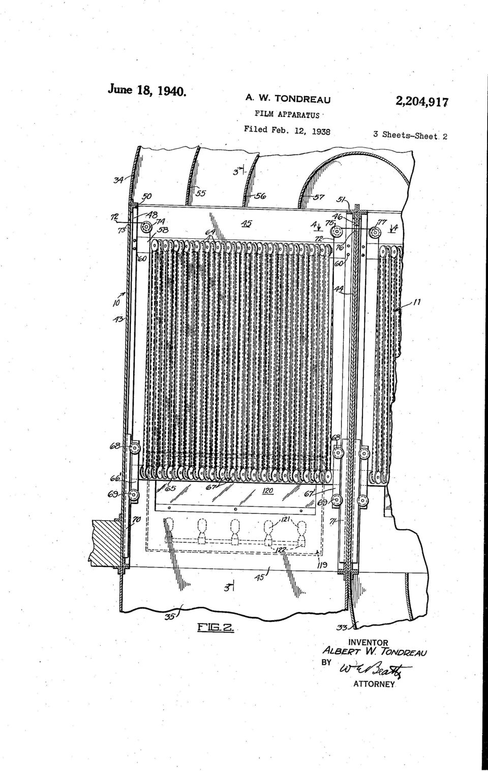
4 _ Patented June 18, 1940 UNITED; STATES PATENT OFFICE >FILM APPARATUS Albert W. Tondreau, Glendale, Calif., assignor to Warner Bros. Pictures, Inc., New York, N. Y., a corporation of Delaware 12, 193g, Serial N0. 190,237 Application February 7 Claims. This invention relates to photographic nlm treating apparatus and has particular reference to apparatus for drying a motion picture >i ilm after it passes through various nlm treating liq 5 uids. In conventional motion picture film drying ap paratus the ñlm is passed endwise through a plurality of substantially parallel elongated loops _ in one or more elongated film drying compart w ments while a current of drying air is passed through the compartments to remove the mois ture adhering to the film. In order to eiîect com pactness of the drying apparatus and to hold a maximum amount of iilm in each compartment i5 at any one time. the iilm loops are generally made comparatively long, on the order of six or seven feet in length. Also the various strands of the «parallel ñlm loops are run as close together as possible. One factor which limits the closeness 20 of the spacing as well as the length of the vari ous film loops is the flapping or swaying of the Various nlm strands dueto the action of the air current thereon, which flapping tends to cause adjacent nlm strands to engage each other and 25 therefore scratch the emulsion surfaces\thereof. Ihis is especially apparent in the early stages of drying wherein the film emusion is very sus ceptible to scratching.due to its soft and sticky nature duringthat period. It is to be noted that 30 the apparently obvious remedy of stretching or tensioning the filmias,by introducing a lhigh spreading force between the ñlm guiding means at either end of the variouslñlm loops cannot be resorted to due to the relatively low tensile strength of the film, the ease with which the sprocket perforations thereof can be enlarged or torn out completely while the ñlm is being drawn under tension by a ñlm driving sprocket, as well as due to the detrimental stretching c_ñect 40 on the ñlm while it is wet. One object of the present invention is to reduce the flapping action ofthe film strands in a plu rality of elongated film loops while being dried by a current of air. I. A further object of the invention is to improve the facilities for inspecting the îiilm while it is passing through-thedry box without interfering with the flow of air through the iilm drying com partment. A further object of the invention is to improve the nim drive, particularly for a plurality of ad jacent film compartments. A still further object of the invention is to prevent an edge cr side thrust of an elongated u film while passing over a plurality of spaced (Cl ) spool heads, and/or while passing from one com partment to another. _I he manner in which the aboveand other ob- >jects of the invention are accomplished will be readily understood on reference >to the accom- 5 panying speciñcation read in conjunction with the accompanying drawings wherein: Fig. 1 is a schematic elevational view of a film drying apparatus embodying my invention. Fig. 2 is a sectional, elevational view taken I0 longitudinally through one of the drying com partments of the apparatus. Fig. 3 is a transverse view, partly in section, of a pair of the ñlm compartments, the sectional portion thereof being along the line 3-3 of Fig. 2. l5 Fig. 4 is a sectional plan view through the iilm guiding spool and ñlm sprocket assembly for passing the film successively from one compart ment to an adjacent compartment, and is taken along the line 4-4 of Fig. 2; 20 Fig. 5 is a sectional view of the ñlm driving sprocket and its associate mechanism. and is taken along the line 5-5 of Fig. 4. Referring particularly to Fig. 1, the film dry- _ ing apparatus comprises a row of vertically ex- 2li tending juxtaposed ñlm drying compartments III, il, I2, I3, I4 and I5. These compartments are placed end to end and are supported in an open ing I6 formed in asupporting floor I1. Condi- I tioned drying air is supplied by an air condi- 30 tioning unit, generally indicated at I8, and is >passed in succession through the various com partments I0 to I5, inclusive, by a blower unit. I9. Air conditioning unit I8 may be of conven tional construction, means being associated there- with to regulate the temperature and humidity of the air passed therethrough to suit the dry _ing requirements of the various compartments. The unit I8 is supported on a lower ñoor 2 and has the inlet conduitv 22 thereof opening 40 exteriorly of the room 23 formed in part by the upper and lower floors Il and 2i and by walls 20 and 20. The outlet conduit 24 of the air conditioning unit I8 opens.upwardly into a lon gitudinally extending conduit,25.y Conduit 25, at 45 ~ one end thereof, opens into the inlet of blower unit I9 which is shown diagrammatically as comprising a centrifugal blower 26 driven by an elelxtric motor 21. The blower 26 exhausts the air drawn through the conduit 25 upwardly sq through a vertically extending rectangular duct 28 communicating with the lower opening of the drying compartment I5.. A semicircular duct 30 communicates the up per opening of the compartment l5 with the mi

5 ` upper opening of the next adjacent compartment I4 to convey the air passing upwardly through the compartment I5 successively down through the compartment I4. A lower semi-circular duct 3l similar to that of 30, extends across the lower openings of the adjacent compartments I3, and I4 to direct the air up through the compart ment I3 after passing through the compartment I4. Upper and lower ducts 32, 33 and 34 simi lar to those at 30 and 3I extend across the upper and lower openings of the compartments I 0 to I3, inclusive, to successively pass the conditioned drying air through these various compartments. The air on being passed through the compart ment I0 is exhausted through a vertically ex tending duct opening into an exhaust con duit36 communicating with the exterior of the room 23. _ The longitudinally extending conduit 25 opens at the end thereof opposite the blower unit I9 into the conduit,36 and is adapted to be closed by a swinging valve diagrammatically indicated at 38 and pivoted at 39. Valve 38 may be swung through an arc of 90. tween the surface of the spool over which it is to close the exhaust con- duit 36 and communicate the exhaust duct being threaded and the edge of the next suc with the conduit 25. A valve 40, similar to that ceeding spool supporting projection 63. of 39, is provided at the juncture of the con A lower spool head is provided, comprising a duits 24 and 25 and is pivoted at 4I to permit horizontally extending channel member 65 (Figs. the conduit 24 to be closed. Zand 3). A plurality of horizontally spaced pro By moving each of the valves 38 and 40 through jections 66 extending inwardly from the member an angle of 90"` from the position illustrated by 65 rotatably support a plurality of film spools the dotted lines in Fig. 1 so as to close the con 61. The axes of spools 61 are arranged in a com duits 36 and 24 respectively, the air forced mon horizontal plane, all being parallel with each through the various drying compartments by the other, and arranged at an angle of 45 to the blower unit I9 may be re-circulated through the length of the member 65, and at 90 to the axes closed circuit thusformed, if desired. Also, the of the upper film spools 64. The channel mem valves 38 and 40 may be adjusted in any midway ber 65 has a pair of cross heads 66 and 61 positions so as to permit bi-passing or re~circu formed at either end thereof. Grooved rollers lating of part of the conditioned air while adding thereto and exhausting therefrom measured por tions of air. Referring now to Figs. 2 and 3, the compart ment I 0 is illustrated in detail and comprises vertically extending end Walls 43 and 44, anda back wall 45. Vertically extending structural angle members as at 46, 41 and 48 formingcor ner posts are mounted in each corner of the com partment I 0 to support the-end and back Walls 43, 44 and 45, respectively. Transversely extend ing angle members 50 and 5I are provided across the upper ends of the compartment end walls 43 and 44 to form a means for lsecuring the semi circular duct 34 to the upper end of compartment 0.. It will be noted in Fig. 3 that the sides 52 and 53 of the semi-circular- duct 32 are substantially flush with the back and front walls 45 and 54, respectively, of the compartment I0, thus form ing a smooth passage at least in a transversely extending direction. Transversely extending semi-circular vanes 55, 56 and 51, concentric with the outer shell of the duct 34, lare mounted in this duct to guide a current of air in a semi circular path from the compartment II to the compartment I0 in a uniform cross sectional movement, thus preventing bouncing of the air from one wall to another as it passes from one compartment to the other. -That is, a uniform velocity is maintained throughout the entire cross~sectional area of the air current passing downwardly from the exit opening of the duct 32. Similar vanes are provided in the other semi circular ducts 30 to 33, inclusive. An upper spool head or bar in the form of a horizontally extending channel member 68 is secured between the rear anglemembers 46 and 48 by bolts 60.- The forward or inner face 56 of the channel 58 lies ñush with the rear wall 45 to form a smooth passage for the air current passing through the compartment I0. As shown in detail in Fig. 5, the ends 6 and 62 of the wall 45 adjacent the channel 58 are bent inwardly forming flanges which fit against the upper and lower legs of the channel 58 and are suitably se cured thereto. Referring now to Figs. 4 and 5 in particular, spaced projections 63_formed on the channel member 58 extend into the compartment I0. Each of the projections 63 rotatably supports a film guiding spool 64 with the axis thereof ex tending at an angle of 45 to the length of the channel member 58. The adjacent overlapping end faces of the various spools 64 are spaced apart sufficiently to allow threading of the ñlm on these various spools by sliding the film trans versely therebetween. This obviates the neces sity of passing the leading end ofl the ñlm be 68 and 69 are rotatably mounted at either end " of each of the cross heads 66 and 61, these rollers being guided vertically along respective vertical guide rails 10 and 1I suitably secured to the end walls 43 and 44, respectively, of the compart ment I0. This arrangement permits the various spools 61 carried by the channel member 65 to be reciprocated vertically permitting the length of film in the compartment to be varied as desired and to compensate for shrinkage of the film as it is dried. f It will be noted that the size and spacing of the various upper and lower film spools 64 and 61, re spectively, are such that the path of the film 12 as it passes from a lower spool 61 to an upper spool 64 (Fig. 4) is at right angles to the axis of rota tion of >both of those film spools. I he same is true of the film path between all sets of upper and lower spools. That is, the film as it passes from the center of the periphery of the take-oil side of a lower spool 61_to the center of the pe riphery of the take-on side of. the next upper spool 64 passes in a vertical direction and al~ though it twists about an angle of 90 during its. travel, the right angle relation above described results in the center of the periphery C (Fig. 4) of each upper spool 64 being directly in line with the corresponding center of the periphery of the aligned lower spool 61. Thus the ñlm as it passes in a series of sinuous loops is restrained from side thrust while passing over the various spools. Ihe above described angular arrangement of film guiding spools is disclosed and claimed in the co-pending patent application of A. W. Munson. ñled July 28, 1936, Serial No. 93,042. It will be noted on reference to Fig. 3 that a second row of ñlm compartments, generally in dicated at 18, is situated closely adjacent and

6 _ v f 1o 15 2c compartment. 75 parallel to the above described row of film com partments, and is of identical construction-but placed in a back to back relation to the row of compartments I8 to I5, inclusive. vthis second row 18 is supplied with conditioned drying air by a conduit and blower system not shown but similar to that shown in Fig. 1. However, the same air conditioning unit I8 of Fig. 1 may be employed, using a common outlet manifold (not shown) in lieu of the outlet conduit 24 to supply conditioned air to boththe conduit 25 for the row of compartments >I8 to I5, inclusive, and a similar.conduit for the row 18 from the unit I8. It will be noted in Fig. 2 that the film 12, on entering the compartment 8 from the various film treating solutions (not shown) which leave the film in4 a wet condition, passes through an opening 13 and is drawn over a film drive sprocket 14 extending into the compartment I8 and hav ing its axis at right angles to the average path of the film through the compartment. Film 12 on leaving the compartment I8 passes over a freely rotatable transfer or guide spool 15, through an opening 18 in the adjacent end walls of the compartments I8 and Il, and is thence drawn by means of a?llm transfer spool or sprocket v11 into the compartment `I I.. I he drive for the sprocket 11 as well as the support for both the sprocket 11 and spool 15 is shown in detail in Figs. 4 and 5. A horizontally extending support or bracket 88 is secured at one end thereof on top of the ~channel member 58 adjacent the right hand end of compartment I8 by volts, one of which is shown at 8l. l.he other end of the support 88 (not shown) _is sup ported on a similar channel member provided in an opposite parallel fllmcompartment. A longitudinally extending drive shaft 82, exteriorly of the compartment I8, is mounted in a ball bearing, indicated by the dotted lines 83 carried in a bearing housing 84 formed on the support 88. Shaft 82 is coupled by means of a flexible, coupling 19 to a co-extensive drive shaft 85 ro tatably mounted at the left hand end thereof in abearing 88 carried by a support 81, similar to that of 88. A similar support and bearing are provided at each end `of each of the compart ments I8 to I5, inclusive, to rotatably support coextensive shaft sections similar to those of 82 and 85, each extending the length of its respective As shown in Fig. 5 a vertically extending stub shaft 88 is rotatably mounted in a bearing 88 integrally formed in the support 81. The axis of the shaft 88 intersects the axis of shaft sec tion 85 at right angles _thereto and is rotatably connected thereto by means of a _pair of bevel gears 88 and 8 secured to the shafts 85 and 88, respectively. A bevel gear 92 securedat the upper end of stub shaft 88 meshes with a-mat ing bevel gear 83 secured at the end of a sprocket shaft 94 extending-horizontally at right angles to the shaft 88. Shaft 84 carries at theopposite end thereof the film sprocket 11 and is rotatably journalled within a bearing 95 >supported by brackets 81 from a sector shaped plate 88. Bear ing 96 extends through an enlarged aperture 25 formed in the wall 45. Plate 88 is slidable _on. the upper surface,of the support 81 andhas a depending circular bearing sleeve 88, co-axial with the shaft 88 and rotatably received within ` a socket 8 formed in the upper surface of the support 81. Av pair of elongated arcuate slots 82 and 83 are formed in the plate 88 extending concentric with the boss lun. Bolts m and unsr extend through slots 82 and 83, respectively, and are threaded in the support 81 to lock the plate 88 in different angular positions. Thus it will be seen that the position of the ñlm sprock et 11 may be vshifted about the axis of the shaft 88. This maybe done either while the appa ratus is in operation or stationary. The spool 15 for guiding the film 12 onto the sprocket 11 is supported in a manner similar to that of the sprocket 11. A bearing support mem -ber 81 extending through an enlarged aperture 26 in wall 45 is provided to rotatably support the shaft (not shown) of the spool 15. Mem ber 81 is supported through suitable brackets upon a sector plate member 88 pìvotally mount ed, in a manner similar to that shown in Fig. 5. to the support 88 for movement about an axis intersecting the axis of the shaft section 82 at right angles thereto. That is a bearing boss, indicated by the dotted lines 85, depends from 20 the plate 88 and is mounted in a corresponding socket formed in the bracket 88. Clamp screws I 8 and extending through arcuate slots H2 and H3, respectively, concentric with the bear- _ ing 85, are threaded in the support 88 to clamp 28 the plate 88 and consequently the spool 15 in different angular positions..,after the various film compartments I8, i I etc. are aligned in substantially their proper relative positions the respective clamp screws for the plates 88 and 88 are loosened to permit the spool 15 in sprocket 11 to be adjusted in proper posi tion relative to each other and to the correspond ingv lower spools from and to which the film passes before and after travelling over the spool 15 and sprocket 11. These clamp screws are then per manently locked. This provision permits an ac curate parallelalignment of the spool 15 and v sprocket 11 with each other even though the compartments I8 and II may be slightly mis aligned with each other, thus preventing a side thrust from being exerted by the film against the edge flanges of the spools and sprocket I5 and 11, respectively. As shown in Figs. 1, 3 and 4 a pair of doors II4 and I 5 cover the front of each of the film compartments I8 to I5, inc1usive._ These doors open at their adjacent ends to permit threading, inspection or repair-.of the film in the compart ments andare vertically khinged as at IIS to either end of each compartment. Windows II1 and I8 are provided in the doors I4 and H5, respectively, to permit inspection of the film trav eling through the >respective compartment. A film illuminating4 compartment generally in dicated at I 8 (Figs. 2 and 3) provided adja cent the lower end of each film compartment to illuminate the.film passing through the com partment as well as theinterior of the compart ment itself. Compartment I8 -is substantially rectangular in shape, one wall thereof being formed in part by the wall 45 of the film com- < glass win-. partment. A translucent or frosted dow pane 28 is situated adjacent the top of the compartment _I8 and forms the remainder of the wall intermediate the compartments I8 and 8. A plurality of spaced illuminating lamps 2I are mounted in sockets 22 suitably sup ported from the rear wall I 23 of the compartment I8. Lamps 2 are situated below the lower edge of the pane 28. The upper portion of wall 23 slopes inwardly at 24 toward the top there of to form a refiector to reflect the light from lamps 2 onto the surface of the ground glass pane 28 and thus uniformly illuminate the en tire area thereof. - 3 Il
 in lieu of the outlet conduit 24 to supply conditioned air to boththe conduit 25 for the row of compartments >I8 to I5, inclusive, and a")
7 f 4 When the drying apparatus is in operation an operator on viewing the film illuminated by the light from lamps IZI passing through the trans lucent pane 20, may determine whether or not the film is being thoroughly dried during its pas sage through the various compartments. If more or less drying is required the temperature or humidity of the conditioned drying air may be regulated as desired. Also, the speed of the 10 film may be varied to produce a greater or less drying effect on it for a given degree of temper ature and humidity of the drying air. The position of the window 20 of compart ment H9 substantially flush with the inner sur 15 face of the wall 45 of compartment I 0, assists in forming a smooth, unbroken air passage throughout the length of the compartment I0. A further factor in producing a smooth passage way through compartment Ill is the provision of 20 the upper spool head or bar 5B with the inner face thereof co-extensive with the inner surface of the wall 45. With this construction it will be seen that there are no large obstructions or re cesses in the compartment l0 to deiiect or ob 25 struct the passage of drying air through the compartment I0 and thus cross currents which would result in fiapping or swaying of the var ious strands of the loops of film passing through the compartment. 30 While the ñlm driving. apparatus above de 40 scribed has been illustrated in connection with the dry end of film processing, it may be used in the wet end, or in a storage elevator, or the like. I claim: 1. Film treating apparatus comprising a com partment having walls, an inspection window in one Wall of said compartment, a translucent pane in an opposite wall of said compartment, means on the exterior o? said compartment and on the side thereof adjacent said pane for illuminating said pane, means for passing a film treating fluid through said compartment, means comprising a lower spool head for passing a. film through said compartment behind said window and within the 45 illumination of said pane, and lguide rails in said compartment.for supporting said lower spool head for vertical movement across the front of said pane. 2._ Means.for driving a film through a current 50 of drying air in a drying compartment while i1 luminating the film for inspection purposes With out thereby substantially producing eddy cur rents in the drying air comprising thei combina tion of a film drying compartment having a transparent front wall and a back wall, an upper spool head flush with saidback wall, a lamp com partment having a window substantially flush with said back Wall, a lowerv spool head in front of said back wall, and means supporting said lower spool head for vertical movement across said window. 3. A film drying apparatus comprising a film compartment having walls, a spool head in said compartment, means for fixedly supporting said spool head with the side thereof facing the in terior of said compartment in the plane of the inner face of one of said walls, a plurality of film guiding spools, means extending into said compartment from said spool head for..rotatably supporting said spools, means cooperating with said spools for supporting the film in a plurality of loops, and means for passing a current of air longitudinally through said compartment. 4. A film drying compartment according to claim 3 comprising a drive shaft bearing member supported by said spool head, a drive shaft ro tatably supported by said member, a horizontal sprocket shaft rotatably supported by said mem ber, and a vertical stub shaft rotatably carried by said member, and geared to said drive shaft and said sprocket shaft A film drying compartment having wall sec tions spaced apart vertically in a plane, a hori ziontal spool head in the space between said sec tions and secured thereto and having the inner face thereof in said plane, means cooperating with said spool head for supporting the film in loops, and means whereby to direct ñlm drying fluid through said compartment. 6. Apparatus for guiding an elongated film in a predetermined path comprising upper and lower spool heads adapted to guide a film there around in a plurality of loops through said path, a transfer spool, means for rotatably supporting said transfer spool with the axis thereof in a fixed angular relation to said path, a second transfer spool, means for rotatably supporting said second transfer spool, means whereby the axes of said transfer spools may be angularly ad justed in a substantially horizontal plane relative to said path to guidesaid film without side thrust, and means for driving said second transfer spool to drive the film. l 7. Apparatus for guiding an elongated photo graphic film comprising a plurality of juxtaposed film compartments, means for guiding the film through each of said compartments, a film driv ing spool for driving the film from said film f guiding means in one compartment to said film guiding means in an adjacent compartment, means for rotatably supporting said spool, means -whereby the axis of said spool may be angularly adjusted in a horizontal plane to guide said film therebetween without side thrust, and means for driving said spool. ~, ALBERT W. TONDREAU

NOV. 21, 1967 P J, FELLNER, JR 3,353,652 FEEDING AND INDEXING DEVICE FOR PACKAGE HANDLING APPARATUS. Filed May 25, 1967 2 Sheets-Sheet 1 /, 27
 NOV. 21, 1967 P J, FELLNER, JR FEEDING AND INDEXING DEVICE FOR PACKAGE HANDLING APPARATUS Filed May 25, 1967 2 Sheets-Sheet 1..Z., 76 60 A5 27 Q2 29 /, 27 a0 /@ /5 70 74 4 /9.32 5.77% ATTO 2N EY v Nov.
I4 '2 ORLANDO J. CHIAPPE Y.
 '. ' Dec. 6, 1960 o. J. GHIAPPE 2,963,058 DIE FOR BELLOWS 0R CORRUGA'l- ING MACHINE Filed Jan. 20, 1958 5 Sheets-Sheet 1 ' INVENTOR. I4 '2 ORLANDO J. CHIAPPE Y. - ATTORNEY _ Dec. 6, 1960 o. J. CHIAPPE
H. G. SHORTT. VACUUM -AGTUATED SCREEN. MPL'IOATION FILED 13.80.19, 1907. 4 SHEETS-SHEET 1.
 No. 896,473. - PATBNTED AUG. 18,1908. ` H. G. SHORTT. VACUUM -AGTUATED SCREEN. MPL'IOATION FILED 13.80.19, 1907. 4 SHEETS-SHEET 1. No. 896,473. PATENTED AUG. 18, 1908.VA` > H. G. 'SH0RTT~ VACUUM AGTUATBD
Oct. 31, 1939. ' E_ Ross 2,177,788 FILM MARKING DEVI CE ATTORNEY
 Oct. 31, 1939. ' E_ Ross 2,177,788 FILM MARKING DEVI CE Filed Sept. 14, 1934 3 Sheets-Sheet l ATTORNEY Oct. 313, 1939, l- E, Ross 2,177,788 FILM MARKING DEVICE Filed Sept. 14, 1934 3 Sheets-Sheet 2 \\
Feb. 21, 1967. o. J. B. ORWIN ETAL 3,305,058. Filed March 2, 1965 2 Sheets-Sheet 1' OVER-LOAD CLUTCH. DAVID Tenn FORTuNé
 Feb. 21, 1967 o. J. B. ORWIN ETAL Filed March 2, 1965 2 Sheets-Sheet 1' DAVID Tenn FORTuNé ' Feb. 21, 1967 o. J. B. ORWIN ETAL. Filed March 2, 1965 2 Sheets-Sheet,2 H57. 4 IN VENT'ORS. OLAF :mw 60mm»!
.711 vem or: 3,274,449. Sept. 20, 1966. Werner Pioch. (44%! / ##1## Altorne y W. PIOCH. Filed NOV. 12, 1963. 5 Sheets-Sheet 1
 W. PIOCH ELECTRICAL APPARATUS COMPRISING PRINTED CIRCUIT BOARDS Filed NOV. 12, 1963 5 Sheets-Sheet 1.711 vem or: by (44%! / ##1## Altorne y W. PIOCH ELECTRICAL APPARATUS COMPRISING PRINTED CIRCUIT BOARDS
June 2, 1964 J. w. COLE ETAL 3,135,148
 June 2, 1964 J. w. COLE ETAL 3,135,148 METHOD OF MACHINING MATERIALS Original Filed July 30, 1956 4 Sheets-Sheet 1 June 2, 1964 J. w. COLE ETAL 3,135,148 METHOD OF MACHINING MATERIALS Original Filed July
Aug. 28, 1956. Filed July 5, 1955. J. W. VAN RIPER l 2,760,230 PLASTIC MATERIAL EXTRUSION HEAD. 2 Sheets-Sheet l
 Aug. 28, 1956 Filed July 5, 1955 J. W. VAN RIPER l 2,760,230 PLASTIC MATERIAL EXTRUSION HEAD 2 Sheets-Sheet l u Mí Aug. 28, 1956 Filed July 5, 1955 J. w. VAN RIPER PLASTIC MATERIAL EXTRUSION HEAD 2,760,230
' July 28," 1925. 1547,685 A. RHODES. EXTENSION TABLE. Filed Feb. 25, 1922 3 Sheets-Sheet 1. Hill. mmm; Anita Rhodes,
 July 28," 1925. 1547,685 A. RHODES. EXTENSION TABLE Filed Feb. 25, 1922 3 Sheets-Sheet 1 Hill mmm; 4 Anita Rhodes, July 28, 1925,. A. RHODES EXTENSION TABLE 1,547,685 Filed Feb. 25. 1922 3 Sheets-Sheet
, $55 WW 1 a 3 _g_ 3l_
 v Nov. 21, 1961 Y. c. BURNETT 3,009Q737 SEAT MOUNTED UTILITY TABLE Filed Méy 2a, 1960 / O 5 sheetisheet 1 _, dad /20?zz "Z? I IJL/BG / v40 L/ 24 I] 4//4o //2@ I 22 //Z6 W m, $55 WW 1 a 3 _g_ 3l_ 12 _/
3,2 74,344 AUTOMATIC DIALING DEVICE. Filed June 14, 1963. 5 Sheets-Sheet 1 24 \ l NVENTOR. CHARLES C. YOUNG / /////% B73744 2?
 Sept. 20, 1966 Filed June 14, 1963 c. c. YOUNG AUTOMATIC DIALING DEVICE 3,2 74,344 5 Sheets-Sheet 1 3 w. L? U; / m wk, m 5 V/Wh :: ///////,// F G 2 w 24 \ / /////% 2-4 l NVENTOR. CHARLES C. YOUNG B73744
Dec, 2, 1969 H. DLUHY 3,481,298 SECURING SYSTEM FOR DECK CONTAINER OR THE LIKE
 Dec, 2, 1969 H. DLUHY 3,481,298 Dec. 2, 1969 H. DLUHY 3,481,298 Filed June 14, 196B 3 Sheets-Sheet 2 :ml NIW) "HW im. Dec. 2, 1969 H. DLUHY 3,481,298 Filed June 14, 1968 5 Sheets-Sheet 3 A7 7 UPA/5X5 _
Umted States Patent [19] [11] Patent Number: 4,854,653 Lakso [45] Date of Patent: Aug. 8, 1989
![Umted States Patent [19] [11] Patent Number: 4,854,653 Lakso [45] Date of Patent: Aug. 8, 1989](/thumbs/27/10122812.jpg "Umted States Patent [19] [11] Patent Number: 4,854,653 Lakso [45] Date of Patent: Aug. 8, 1989") . Umted States Patent [19] [11] Patent Number: 4,854,653 Lakso [45] Date of Patent: Aug. 8, 1989 * [54] MULTIPLE INTERLOCKING SYSTEM FOR [56] References Cited FILE CABINETS, E.G. U.S. PATENT DOCUMENTS
. Umted States Patent [19] [11] Patent Number: 4,854,653 Lakso [45] Date of Patent: Aug. 8, 1989 * [54] MULTIPLE INTERLOCKING SYSTEM FOR [56] References Cited FILE CABINETS, E.G. U.S. PATENT DOCUMENTS
Nov. 20, 1951 2,575,555 P. W. L_A PLANTE PERPETUAL CALENDAR. 4 Sheets-Sheet l. Filed June 23. 1949. 3mm R WLa/Dianîe 01M
 Nov. 20, 1951 Filed June 23. 1949 P. W. L_A PLANTE PERPETUAL CALENDAR 4 Sheets-Sheet l 3mm R WLa/Dianîe 01M Nov. 20, 1951 Filed June 23. 1949 P. w. LA PLANTE PERPETUAL CALENDAR 4 Sheets-Sheet 3 32» 27
WOVEN WIRE BELTING 2,244,422. Filed Nov. 19, 1958 2 SheetsLSheat 1
 Jime 3, 1941. R. J. GUBA WOVEN WIRE BELTING 2,244,422 Filed Nov. 19, 1958 2 SheetsLSheat 1 June 3, 1941..R. J. GUBA ` 2,244,422 WOVEN WIRE BELTING Filed Nov. 19, 1938 2 Sheets-Sheet 2 @a Je 9 a5 ß m. m
US 20140196633A1 (19) United States (12) Patent Application Publication (10) Pub. N0.: US 2014/0196633 A1 Shaw (43) Pub. Date: Jul.
 United States (12) Patent Application Publication (10) Pub. N0.: US 2014/0196633 A1 Shaw (43) Pub. Date: Jul.") US 20140196633A1 (19) United States (12) Patent Application Publication (10) Pub. N0.: US 2014/0196633 A1 Shaw (43) Pub. Date: Jul. 17, 2014 (54) SECONDARY CONTAINMENT PALLET (52) US. Cl. HAVING FLEXIBLE
US 20140196633A1 (19) United States (12) Patent Application Publication (10) Pub. N0.: US 2014/0196633 A1 Shaw (43) Pub. Date: Jul. 17, 2014 (54) SECONDARY CONTAINMENT PALLET (52) US. Cl. HAVING FLEXIBLE
Ulllted States Patent [19] [11] Patent Number: 6,009,588. Rutkowski [45] Date of Patent: Jan. 4, 2000
![Ulllted States Patent [19] [11] Patent Number: 6,009,588. Rutkowski [45] Date of Patent: Jan. 4, 2000](/thumbs/30/13940583.jpg "Ulllted States Patent [19] [11] Patent Number: 6,009,588. Rutkowski [45] Date of Patent: Jan. 4, 2000") US006009588A Ulllted States Patent [19] [11] Patent Number: 6,009,588 Rutkowski [45] Date of Patent: Jan. 4, 2000 [54] DRAIN CLEANING APPARATUS 4,686,732 8/1987 Irwin..... 15/104.33 4,914,775 4/1990 Kirk..
US006009588A Ulllted States Patent [19] [11] Patent Number: 6,009,588 Rutkowski [45] Date of Patent: Jan. 4, 2000 [54] DRAIN CLEANING APPARATUS 4,686,732 8/1987 Irwin..... 15/104.33 4,914,775 4/1990 Kirk..
A Practical Guide to Free Energy Devices
 A Practical Guide to Free Energy Devices Electrolysis Patents No 14: Last updated: 28th January 2006 Author: Patrick J. Kelly Please note that this is a re-worded excerpt from this patent. If the content
ATTORNEYS. June 16, 1953 - M. _. GOODMAN A 2,642,189. Filed July 25, 1952 2 Sheets-Sheet 1. BY WHITEHEAD 8x VOGL IN V EN TOR. MERL L.
 June 16, 1953 - M. _. GOODMAN A 2,642,189 " TIMECARD RACK Filed July 25, 1952 2 Sheets-Sheet 1 IN V EN TOR. MERL L. GOODMAN BY WHITEHEAD 8x VOGL I a L. I P" ATTORNEYS June 16, 1953 Filed July 25, 1952
llllllllllllllillllllllllllllllllllllllllllllllllllllllllllllllllllllllllll
 United States Patent [191 Rennie et al. llllllllllllllillllllllllllllllllllllllllllllllllllllllllllllllllllllllllll USOO5574624A [11] Patent Number [45] Date of Patent: : 5,574,624 NOV. 12, 1996 [54] VENTILATION
TEPZZ 8 8 A_T EP 2 811 282 A1 (19) (11) EP 2 811 282 A1 (12) EUROPEAN PATENT APPLICATION. (51) Int Cl.: G01N 3/04 (2006.01) G01N 3/08 (2006.
 (11) EP 2 811 282 A1 (12) EUROPEAN PATENT APPLICATION. (51) Int Cl.: G01N 3/04 (2006.01) G01N 3/08 (2006.") (19) TEPZZ 8 8 A_T (11) EP 2 811 282 A1 (12) EUROPEAN PATENT APPLICATION (43) Date of publication:.12.14 Bulletin 14/0 (1) Int Cl.: G01N 3/04 (06.01) G01N 3/08 (06.01) (21) Application number: 14170412.2
(19) TEPZZ 8 8 A_T (11) EP 2 811 282 A1 (12) EUROPEAN PATENT APPLICATION (43) Date of publication:.12.14 Bulletin 14/0 (1) Int Cl.: G01N 3/04 (06.01) G01N 3/08 (06.01) (21) Application number: 14170412.2
-uif 3,332,730. July z5, i967. Filed Oct. 24, 1965. INVENTORâ. A70/wu@ W. /PUß//v 7750@ TOPO/r R. W. RUBIN ET AL. 2 Sheets-Sheet l STORAGE UNIT
 July z5, i967 Filed Oct. 24, 1965 R. W. RUBIN ET AL STORAGE UNIT 2 Sheets-Sheet l -uif ìlml" /4 INVENTORâ. A70/wu@ W. /PUß//v 7750@ TOPO/r A fromm/5k5 _ United States Patent O Ffice 3,332,73` Patented
2,662,310 AUTOMATICALLY REVERSIBLE CURRENT-DRIVEN CHANNEL CLEANER. Filed Jan. 4, 1951. 2 Sheets-Sheet 1. Mté/M 6M), Tpw-méeudr ' INVENTOR.
, Tpw-méeudr ' INVENTOR.") Dec- 15, 1953 0. DE VlLLOTA 2,662,310 AUTOMATICALLY REVERSIBLE CURRENT-DRIVEN CHANNEL CLEANER Filed Jan. 4, 1951 2 Sheets-Sheet 1 / BY ' INVENTOR. I Mté/M 6M), Tpw-méeudr Dec. 15, 1953 c. DE ViLLOTA 2,662,310
Dec- 15, 1953 0. DE VlLLOTA 2,662,310 AUTOMATICALLY REVERSIBLE CURRENT-DRIVEN CHANNEL CLEANER Filed Jan. 4, 1951 2 Sheets-Sheet 1 / BY ' INVENTOR. I Mté/M 6M), Tpw-méeudr Dec. 15, 1953 c. DE ViLLOTA 2,662,310
' 2,092,586 SCREW DRIVER. Filed July 24, 1936. ' 2 Sheets-Sheet 1 INVENTOR. Sl qjarz Mama/{ck 1 _ / ' ATTORNEY
 Sept. 7, 1937,, s. N'AuMovlcH SCREW DRIVER Filed July 24, 1936 ' ' 2 Sheets-Sheet 1 INVENTOR Sl qjarz Mama/{ck 1 _ / ' ATTORNEY I Patented Sept. 7, 1937 UNITED STATES SCREW DRIVER PATENT OFFICE Stojan
TABLE OF CONTENTS. I. TROUBLESHOOTING... 2 - Section 1.01: Common Problems/Solutions... 2
 BAL Accu-Slide System I. Table of Contents TABLE OF CONTENTS I. TROUBLESHOOTING... 2 - Section 1.01: Common Problems/Solutions... 2 II. GETTING STARTED... 5 - Section 2.01: Tools You Will Need... 5 - Section
1iillllllllllllllilllllllllllllllllllllllllllllllllillllllllllllllllllllill
 1iillllllllllllllilllllllllllllllllllllllllllllllllillllllllllllllllllllill USO05615608A Ulllt d States Patent [19] [11] Patent Number: 5,615,608 Shaw et a]. [45] Date of Patent: Apr. 1, 1997 [54] REINFORCED
Design and Modeling of Fluid Power Systems ME 597/ABE 591 Lecture 5
 Systems ME 597/ABE 591 Lecture 5 Dr. Monika Ivantysynova MAHA Professor Fluid Power Systems MAHA Fluid Power Research Center Purdue University Displacement Machines Study different design principles and
A Practical Guide to Free Energy Devices
 A Practical Guide to Free Energy Devices Part PatD12: Last updated: 12th February 2006 Author: Patrick J. Kelly This pre-world War I patent shows the details of a device which can produce electricity without
(12) (10) Patent N0.: US 6,634,830 B1 Marshall (45) Date of Patent: Oct. 21, 2003
 (10) Patent N0.: US 6,634,830 B1 Marshall (45) Date of Patent: Oct. 21, 2003") United States Patent US006634830B1 (12) (10) Patent N0.: US 6,634,830 B1 Marshall (45) Date of Patent: Oct. 21, 2003 (54) METHOD AND APPARATUS FOR POST- 5,511,909 A * 4/1996 Calandra, Jr. TENSIONING SEGMENTEI)
United States Patent US006634830B1 (12) (10) Patent N0.: US 6,634,830 B1 Marshall (45) Date of Patent: Oct. 21, 2003 (54) METHOD AND APPARATUS FOR POST- 5,511,909 A * 4/1996 Calandra, Jr. TENSIONING SEGMENTEI)
3,213,816. Oct. 26, 1965 42/ V//////////A 22 "71% / ' ///////1 J. SOLANKA. Filed Feb. 25, 1963 2 Sheets-Sheet 1. 34 32 2s 34 3o, 46 48 4o ATTORNEY
 Oct. 26, 1965 J. SOLANKA METHOD AND MEANS FOR SEWING AND SHANKING BUTTONS Filed Feb. 25, 1963 2 Sheets-Sheet 1 J 34 32 2s 34 3o, 46 48 4o Q? V//////////A 22 llhd. I. Val 24 28 _ 42/ "71% / ' ///////1 5o
r... MACHINE FOR SECURING LACING STUDS 0R STAPLES. N0. 466,810. Patented Jan. 12, 1892. Qpu?ial'xus T1,- 026L617 /\.> BY MWOJQ W, ATT Y.
 W 0 M 0 d m I G 0 X L E R TU _ 2 S h e e t S S h 6 MW r... MACHINE FOR SECURING LACING STUDS 0R STAPLES. N0. 466,810. Patented Jan. 12, 1892. WITNESSES ; Qém- INVENTOR'. Qpu?ial'xus T1,- 026L617 /\.> BY
United States Patent [191 Romo et al.
 United States Patent [191 Romo et al. [54] APPARATUS FOR PREVENTING NECK INJURY [76] Inventors: Leon E. Romo, Box 1 A Rt. 5, Annapolis, Md. 211; Jack T. Andrish, 120 E. 216 St., Euclid, Ohio 44123 [22]
March 2, 1971. J. A. GENTILuoMo 3,567,223 GOLF RANGE BALL HANDLING MEANS. Filed Jan. 20. 1967. 2 Sheets-Sheet 1. BY Mdm
 March 2, 1971 Filed Jan.. 1967 J. A. GENTILuoMo GOLF RANGE BALL HANDLING MEANS 2 Sheets-Sheet 1 BY Mdm l March 2,-11971 J. A. GENTlLuoMo ~ l l GOLF RANGE BALL HANDLING MEANS Filed Jan. 2o, 1967 ' 2 sheets-sheet
' Jan. 24, 1967 E. M. WOODFORD 3,300,697 HYDRAULIC STARTI-NG DEVICE FOR AN ELECTRIC MOTOR WHICH DRIVES HEAVY MACHINE ELEMENTS.
 ' Jan. 24, 1967 E. M. WOODFORD 3,300,697 HYDRAULIC STARTI-NG DEVICE FOR AN ELECTRIC MOTOR WHICH DRIVES Filed Nov; 21, 1963 3 Sheets-Sheet l vyhuii I / f: all; I Ti * ////////////. j y l l -_ \ s/e/wssr
FTC 2015-2016 DIY Mountain Build Guide
 FTC 2015-2016 DIY Mountain Build Guide Assembly Instructions Check out the DIY2015-2016 Prints and BoM for individual part details. Release 1.0 9/10/15 Page 1 This guide and Bill of Materials are for constructing
Ulllted States Patent [19] [11] Patent Number: 5,992,923. Wycech [45] Date 0f Patent: Nov. 30, 1999
![Ulllted States Patent [19] [11] Patent Number: 5,992,923. Wycech [45] Date 0f Patent: Nov. 30, 1999](/thumbs/40/20828367.jpg "Ulllted States Patent [19] [11] Patent Number: 5,992,923. Wycech [45] Date 0f Patent: Nov. 30, 1999") US005992923A Ulllted States Patent [19] [11] Patent Number: 5,992,923 Wycech [45] Date 0f Patent: Nov. 30, 1999 [54] REINFORCED BEAM ASSEMBLY 4,923,902 5/1990 Wycech. 4,978,562 12/1990 Wycech. [75] Inventor:
US005992923A Ulllted States Patent [19] [11] Patent Number: 5,992,923 Wycech [45] Date 0f Patent: Nov. 30, 1999 [54] REINFORCED BEAM ASSEMBLY 4,923,902 5/1990 Wycech. 4,978,562 12/1990 Wycech. [75] Inventor:
United States Patent [191 [11] Patent Number: 4,895,256
![United States Patent [191 [11] Patent Number: 4,895,256](/thumbs/29/13744178.jpg "United States Patent [191 [11] Patent Number: 4,895,256") I United States Patent [191 [11] Patent Number: 4,895,256 Johnston [45] Date of Patent: Jan. 23, 1990 [54] AIR CONDITIONING SUPPLY CARRIER 3,392,874 7/1968 3,627,122 12/1971 [76] Inventor: James E. Johnston,
I United States Patent [191 [11] Patent Number: 4,895,256 Johnston [45] Date of Patent: Jan. 23, 1990 [54] AIR CONDITIONING SUPPLY CARRIER 3,392,874 7/1968 3,627,122 12/1971 [76] Inventor: James E. Johnston,
GEK-90214B. GE Lift Truck. User s Guide 144D2933G1 144D2912G1 144D2911G5
 g GEK-90214B GE Lift Truck User s Guide 144D2933G1 144D2912G1 144D2911G5 GE LIFT TRUCK EACH USER HAS THE RESPONSIBILITY TO INSTRUCT ALL PERSONNEL ASSOCIATED WITH THIS EQUIPMENT ON ALL SAFETY PRECAUTIONS
?84400468r/07 [[1112. mum, Lad. llllllllllllll llllllllllllllllllllllllllllllllllllllllilllllllllllllllll. .liu mma C. United States Patent [191
 United States Patent [191 llllllllllllll llllllllllllllllllllllllllllllllllllllllilllllllllllllllll USO05606963A [11] Patent Number = 5,606,963 Wenzel et al. [45] Date of Patent: Mar. 4, 1997 [54] ATTACHIVIENT
Jet powered watercraft
 ( 11 of 11 ) United States Patent 3,948,206 Tyler April 6, 1976 Jet powered watercraft Abstract A jet powered watercraft of motorcycle-like configuration. Longitudinally aligned front and rear skis are
I BEAM TRACK INSTALLATION
 PDQ 0/700 FESTOON SYSTEM INSTALLATION AND MAINTENANCE INSTRUCTIONS INTRODUCTION The PDQ Festoon System was designed to run on one of three sizes of I-beams: S x., S8 x 8. and S x.. System trolleys must
Drive shaft, servicing
 Volkswagen Passat B6 - Drive shaft, servicing Стр. 1 из 41 40-7 Drive shaft, servicing Drive shafts, overview I - Assembly overview: Drive axle with CV joint VL100 40-7, Drive axle with CV joint VL100,
A LIGHTWEIGHT REAR BUMPER WITH CRASH WORTHY COMPARTMENT
 1 A LIGHTWEIGHT REAR BUMPER WITH CRASH WORTHY COMPARTMENT Background of the Invention Field of the Invention This invention relates to a lightweight rear bumper with crash worthy compartment, and more
(12) (10) Patent N0.: US 6,740,055 B2 Dominguez (45) Date of Patent: May 25, 2004
 (10) Patent N0.: US 6,740,055 B2 Dominguez (45) Date of Patent: May 25, 2004") United States Patent US006740055B2 (12) (10) Patent N0.: US 6,740,055 B2 Dominguez (45) Date of Patent: May 25, 2004 (54) TRAUMA CERVICAL COLLAR 5,016,623 A * 5/1991 Krahenbuhl..... 602/27 5,054,475 A
United States Patent US006740055B2 (12) (10) Patent N0.: US 6,740,055 B2 Dominguez (45) Date of Patent: May 25, 2004 (54) TRAUMA CERVICAL COLLAR 5,016,623 A * 5/1991 Krahenbuhl..... 602/27 5,054,475 A
PART 2 FORKLIFT HYDRAULIC SYSTEM
 PART 2 FORKLIFT HYDRAULIC SYSTEM Chapter 1 Description and Operation Component Locations & Circuit Layouts 1 Hydraulic Pump 11 Control Valve 14 Valve Section Oil Flows 15 Anti-Cavitation Valve 22 Velocity
Dec- 2, 1969 M. v. 8. BROWN ET AL 3,482,037
 Dec- 2, 1969 M. v. 8. BROWN ET AL 3,482,037 HOME SECURITY SYSTEM UTILIZING TELEVISION SURVEILLANCE Filed Aug. 1, 1966 3 Sheets-Sheet 1 VIDEO scaumsn / r55 / I a J Dec. 2, 1969 M. v. B. BROWI-Q ETAL '
United States Patent [19] [11] Patent Number: 5,671,124
![United States Patent [19] [11] Patent Number: 5,671,124](/thumbs/40/20728739.jpg "United States Patent [19] [11] Patent Number: 5,671,124") ' USOO5671124A United States Patent [19] [11] Patent Number: 5,671,124 H0 [45] Date of Patent: Sep. 23, 1997 [54] CIRCUIT BOARD LOCATING DEVICE 3,488,628 1/1970 Lundergan et a1...... 361/767 4,859,108
' USOO5671124A United States Patent [19] [11] Patent Number: 5,671,124 H0 [45] Date of Patent: Sep. 23, 1997 [54] CIRCUIT BOARD LOCATING DEVICE 3,488,628 1/1970 Lundergan et a1...... 361/767 4,859,108
*6/12. Nov. 24, 1953, L. L. BILLAR 2,660,621 OU/S L. BILL/4R. Filed July 14, 1950 IDENTIFICATION CODE ON SOUND RECORDS. 2 Sheets-Sheet l INVENTOR
 Nov. 24, 1953, L. L. BILLAR 2,660,621 Filed July 14, 1950 *6/12 IDENTIFICATION CODE ON SOUND RECORDS 2 Sheets-Sheet l _ '22 A 2/5 VACUUM TUBE AMP. OU/S L. BILL/4R INVENTOR Nov. 24, 1953 L. 1.. BILLAR 2,660,621
Installation Instructions For Slider Casement Air Conditioners
 Installation Instructions For Slider Casement Air Conditioners NOTE: These instructions describe installation in a typical wood framed window with a wood SLIDE-BY sash, or installation in a metal CASEMENT
978,841. 2 8KBBT8 SHEET 1. '
 W. W. BUCKTON. COMBINED ELECTRIC CONNECTION PLUG AND SOCKET AND SWITCH. APPLICATION FILED JUNE 1., 1908. Patented Dec. 20, 1910. 978,841. 2 8KBBT8 SHEET 1. W. W. BUCKTON. COMBINED ELECTRIC CONNECTION PLUG
How To Make An Air Conditioning Apparatus
 June 30, 1942. e. M. KLEUCKER v - I 39238303 AIR CONDITIONING APPARATUS Filed June 12; 1939 3 Sheets-Sheet 1 INVENTOR. GEORG M. KLEUCKER _ q June 30, 1942. G. M. KLEUCKER AIR CONDITIONING APPARATUS Filed
Rebuild Instructions for 70001 and 70010 Transmission
 Rebuild Instructions for 70001 and 70010 Transmission Brinn, Incorporated 1615 Tech Drive Bay City, MI 48706 Telephone 989.686.8920 Fax 989.686.6520 www.brinninc.com Notice Read all instructions before
1,317,044. 3% 5M .ZZOZ67'Z JAY/M75012. é] Mom/W01, '11; f B. J. SHANNON. VEHICLE FOR EMERGENCY PLUMBING OPERATIONS.
![1,317,044. 3% 5M .ZZOZ67'Z JAY/M75012. é] Mom/W01, '11; f B. J. SHANNON. VEHICLE FOR EMERGENCY PLUMBING OPERATIONS.](/thumbs/24/3735325.jpg "1,317,044. 3% 5M .ZZOZ67'Z JAY/M75012. é] Mom/W01, '11; f B. J. SHANNON. VEHICLE FOR EMERGENCY PLUMBING OPERATIONS.") 1,317,044. B. J. SHANNON. VEHICLE FOR EMERGENCY PLUMBING OPERATIONS. APPLICATION FILED APR. 14. I919. Patented Sept. 23, 1919. 2 SHEETS-SHEET 1 [19 Q) 20 '11; f é] Mom/W01,.ZZOZ67'Z JAY/M012 M 3% 5M 1,317,044.
1,317,044. B. J. SHANNON. VEHICLE FOR EMERGENCY PLUMBING OPERATIONS. APPLICATION FILED APR. 14. I919. Patented Sept. 23, 1919. 2 SHEETS-SHEET 1 [19 Q) 20 '11; f é] Mom/W01,.ZZOZ67'Z JAY/M012 M 3% 5M 1,317,044.
Problem Set 1. Ans: a = 1.74 m/s 2, t = 4.80 s
 Problem Set 1 1.1 A bicyclist starts from rest and after traveling along a straight path a distance of 20 m reaches a speed of 30 km/h. Determine her constant acceleration. How long does it take her to
Char-Lynn Hydraulic Motor. Repair Information. 10 000 Series. October, 1997
 Char-Lynn Hydraulic Motor October, 1997 Repair Information Geroler Motor Two Speed 001 27 Retainer inside bore of valve plate bearingless motors only 4 15 16 3 6 35 Parts Drawing 25 2 2 1 19 17 36 40 47
Installation Instructions
 READ BEFORE INSTALLING UNIT For Slider Casement Air Conditioners To avoid risk of personal injury, property damage, or product damage due to the weight of this device and sharp edges that may be exposed:
Operating, Installation, and Maintenance Instructions
 ELKHART BRASS MFG. CO., INC. 1302 WEST BEARDSLEY AVENUE P.O. BOX 1127 ELKHART IN 46515 (574) 295-8330 FAX (574) 293-9914 Operating, Installation, and Maintenance Instructions RAM Personal Portable Monitor
Char-Lynn Spool Valve Hydraulic Motors. Repair Information. W Series Geroler Motors
 Char-Lynn Spool Valve Hydraulic Motors Repair Information W Series Geroler Motors with Parking Brake 004 Nut Key Ring, Retaining Bearing Ring, Retaining Ring, Retaining Washer (Thick), Pressure Washer,
Lathe Milling Attachment
 Lathe Milling Attachment By L C. MASON BY CLEVERLY stacking cold-rolled flat stock together, T-slots and slide for this lathe milling attachment are made without costly machinery. In fact, only two tools,
Module 5 Couplings. Version 2 ME, IIT Kharagpur
 Module 5 Couplings Lesson 1 Introduction, types and uses Instructional Objectives At the end of this lesson, the students should have the knowledge of The function of couplings in machinery. Different
Section 5: Machine Overview
 Section 5: Machine Overview Machine Floor Plan Machine Specifications Sequence of Operation Theory of Operation Sensor Location Floor Plan 2007 Douglas Machine Inc. 5.1 Machine Floor Plan Figure 5.1: Machine
United States Patent [191 [11] Patent Number: 4,732,385
![United States Patent [191 [11] Patent Number: 4,732,385](/thumbs/30/14321926.jpg "United States Patent [191 [11] Patent Number: 4,732,385") United States Patent [191 [11] Patent Number: 4,732,385 Castellanos [45] Date of Patent: Mar. 22, 1988 [54] ROULETTE F 0R GAMI N G FOREIGN PATENT DOCUMENTS [76] Invento? Rodolfo 1,3- castf?lanos, Escalmendi,
United States Patent [191 [11] Patent Number: 4,732,385 Castellanos [45] Date of Patent: Mar. 22, 1988 [54] ROULETTE F 0R GAMI N G FOREIGN PATENT DOCUMENTS [76] Invento? Rodolfo 1,3- castf?lanos, Escalmendi,
THE TRIMLINE 10' x 20' CANOPY
 THE TRIMLINE 10' x 20' CANOPY Instructions for Assembly Please, assemble the TrimLine at home the first time, not at an event. Before beginning assembly of your TrimLine, please take time to review the
POD Visor Instructions
 POD Visor Instructions Please read fully before beginning assembly and mounting the Visor Parts List - Visor Left Part (LV), Visor Right Part (RV) Qty 2, Aluminum Crossbars Hardware - Qty 17, 1/4" X 3/4"
IIIIIIllllllllIllIlllllllllllllllllllllllllllllllllllllllllllllllllllllllll
 .' IIIIIIllllllllIllIlllllllllllllllllllllllllllllllllllllllllllllllllllllllll US005246311A United States Patent [191 [11] Patent Number: West et al. [45] Date of Patent: Sep. 21, 1993. [54] FOUNDATION
2100 AD 015 0009 Mirror Elevator Ball Nut Replacement Procedure
 2100 AD 015 0009 Mirror Elevator Ball Nut Replacement Procedure Derek Guenther 1/28/2015 Rev. Purpose The purpose of this document is to describe the procedure necessary to replace one of the ball nuts
United States Patent [19]
![United States Patent [19]](/thumbs/20/639223.jpg "United States Patent [19]") United States Patent [19] Jackson et al. 111111111111111111111111111111111111111111111111111111111111111111111111111 USOO5255452A [11] Patent Number: 5,255,452 [45] Date of Patent: Oct. 26, 1993 [54] METHOD
United States Patent [19] Jackson et al. 111111111111111111111111111111111111111111111111111111111111111111111111111 USOO5255452A [11] Patent Number: 5,255,452 [45] Date of Patent: Oct. 26, 1993 [54] METHOD
Technical Information
 Technical Information This section of the catalogue provides technical information that will help specify, install and maintain Surelock McGill devices and components. The topics are listed below: Blast
Residential Garage Door Terminology
 A Air Infiltration: The leakage or passage of air through a door system Anodize: A hard non-corrosive oxide film on the surface of aluminum Astragal: A compressible or deformable seal provided on the bottom
(72) Inventors: Juergen RIEDL, Koenigsbrunn (DE); USPC ( 267/285)
 Inventors: Juergen RIEDL, Koenigsbrunn (DE); USPC ( 267/285)") US 20130087957A1 (19) United States (12) Patent Application Publication (10) Pub. No.: US 2013/0087957 A1 RIEDL et al. (43) Pub. Date: Apr. 11, 2013 (54) DEVICE FOR DAMPING THE VIBRATIONS Publication Classi?cation
US 20130087957A1 (19) United States (12) Patent Application Publication (10) Pub. No.: US 2013/0087957 A1 RIEDL et al. (43) Pub. Date: Apr. 11, 2013 (54) DEVICE FOR DAMPING THE VIBRATIONS Publication Classi?cation
31L. (12) United States Patent Ihrke et al. (1o) Patent No.: US 9,149,933 B2 (45) Date of Patent: Oct. 6, 2015
 United States Patent Ihrke et al. (1o) Patent No.: US 9,149,933 B2 (45) Date of Patent: Oct. 6, 2015") 111111111111111111111111111111111111111111111111111111111111111111111111 (12) United States Patent Ihrke et al. (1o) Patent No.: US 9,149,933 B2 (45) Date of Patent: Oct. 6, 2015 (54) GRASP ASSIST DEVICE
111111111111111111111111111111111111111111111111111111111111111111111111 (12) United States Patent Ihrke et al. (1o) Patent No.: US 9,149,933 B2 (45) Date of Patent: Oct. 6, 2015 (54) GRASP ASSIST DEVICE
Model No: VS4815 1. SAFETY INSTRUCTIONS VS4800 2. INTRODUCTION & APPLICATIONS VS4815 3. CONTENTS. 2.1 Introduction. 2.
 Instructions for: Petrol Engine Twin Camshaft Setting / Locking Tool Kit - (incorporating Vanos Alignment) - BMW N42 & N46 Engines Model No: VS4800 Associated kit: Camshaft/Carrier Bracket Remover & Installer
Common Mechanical Engineering Terms
 Common Mechanical Engineering Terms Ball and Detent (n) A simple mechanical arrangement used to hold a moving part in a temporarily fixed position relative to another part. The ball slides within a bored
United States Patent [19] Glover
![United States Patent [19] Glover](/thumbs/29/13251170.jpg "United States Patent [19] Glover") United States Patent [19] Glover [54] WINDOW UNIT [76] Inventor: J. Raymond Glover, 1019 Ave. C, White City, Jackson County, Oreg. 97503 [21] Appl. No.: 975,097 [22] Filed: Nov. 12, 1992 [51] Int. Cl.6.....
United States Patent [19] Glover [54] WINDOW UNIT [76] Inventor: J. Raymond Glover, 1019 Ave. C, White City, Jackson County, Oreg. 97503 [21] Appl. No.: 975,097 [22] Filed: Nov. 12, 1992 [51] Int. Cl.6.....
Suspension and Steering Systems Operation. The Steering/Suspension System (Overview)
") Suspension and Steering Systems Operation Below is an overview of the suspension and steering systems The Steering/Suspension System (Overview) "Suspension," when discussing cars, refers to the use of
Suspension and Steering Systems Operation Below is an overview of the suspension and steering systems The Steering/Suspension System (Overview) "Suspension," when discussing cars, refers to the use of
OWNER S MANUAL Table Tennis Table Patent Pending
 OWNER S MANUAL Table Tennis Table Patent Pending Be sure to write your model number and serial number here for future reference. You can find these numbers printed on the bottom of the table. MODEL # T8179
STEERING SYSTEM - POWER
 STEERING SYSTEM - POWER 1990 Nissan 240SX 1990 STEERING Nissan - Power Rack & Pinion Axxess, Maxima, Pulsar NX, Sentra, Stanza, 240SX, 300ZX DESCRIPTION The power steering system consists of a rack and
Speed-Mat Rectangle Cutter
 Speed-Mat Rectangle Cutter 1 Honeycomb baseboard. 2 Left hold down. 14 3 Bottom hold down. 4 4 Left / right rule. 8 5 8 5 Left / right rule pointer. 1 6 Top / bottom rule. 7 Top / bottom rule pointer.
VS4760.V2. Instructions for: Diesel Engine Setting/Locking Tool Kit Renault dci Engines. Model No: 1. SAFETY INSTRUCTIONS
 Instructions for: Diesel Engine Setting/Locking Tool Kit Renault dci Engines Model No: VS4760.V2 Thank you for purchasing a Sealey product. Manufactured to a high standard this product will, if used according
March 16, 1926. 1,576,993 J. K. PENNINGTON. PLUMBING FITTING AND FIXTURE Filed Jan. l0l 1922
 March 16, 1926. J. K. PENNINGTON PLUMBING FITTING AND FIXTURE Filed Jan. l0l 1922 ` _ y v20 25 ly and withoutnecessitating the cutting or breaking of more or less rigid connection, or in any way dismantling
Gerlack [45] Date of Patent: Apr. 26, 1988
![Gerlack [45] Date of Patent: Apr. 26, 1988](/thumbs/27/10452530.jpg "Gerlack [45] Date of Patent: Apr. 26, 1988") United States Patent [19] [111 Patent Number: 4,740,764 Gerlack [] Date of Patent: Apr. 26, 1988 [54] PRESSURE SEALED WAVEGUIDE T0 2,527,146 10/ 1950 Mumford. COAXIAL LINE CONNECTION 3,086,181 4/ 1963
United States Patent [19] [111 Patent Number: 4,740,764 Gerlack [] Date of Patent: Apr. 26, 1988 [54] PRESSURE SEALED WAVEGUIDE T0 2,527,146 10/ 1950 Mumford. COAXIAL LINE CONNECTION 3,086,181 4/ 1963
(12) United States Patent (10) Patent No.: US 8,253,226 B2 Oguri (45) Date of Patent: Aug. 28, 2012
 United States Patent (10) Patent No.: US 8,253,226 B2 Oguri (45) Date of Patent: Aug. 28, 2012") US008253226B2 (12) United States Patent (10) Patent No.: US 8,253,226 B2 Oguri (45) Date of Patent: Aug. 28, 2012 (54) ELECTRONIC PARTS, AND METHOD FOR (56) References Cited ARRANGING SHIELDING CASE AND
US008253226B2 (12) United States Patent (10) Patent No.: US 8,253,226 B2 Oguri (45) Date of Patent: Aug. 28, 2012 (54) ELECTRONIC PARTS, AND METHOD FOR (56) References Cited ARRANGING SHIELDING CASE AND
(12) United States Patent
 United States Patent") US006582087B2 (12) United States Patent (10) Patent N0.: US 6,582,087 B2 Whitehead et al. (45) Date of Patent: Jun. 24, 2003 (54) EXTENDABLE EXTERIOR REARVIEW D285,549 S 9/1986 Haack..... D12/187 MIRROR
US006582087B2 (12) United States Patent (10) Patent N0.: US 6,582,087 B2 Whitehead et al. (45) Date of Patent: Jun. 24, 2003 (54) EXTENDABLE EXTERIOR REARVIEW D285,549 S 9/1986 Haack..... D12/187 MIRROR
Belt Tensioning Methods for Small Package Conveyors What s the best solution?
 Belt Tensioning Methods for Small Package Conveyors What s the best solution? Industrial White Paper By: Michael A. Hosch, P.E. Dorner Mfg. Corp. 975 Cottonwood Avenue Hartland, WI 53029 USA Phone: 800
Series 30000 Hose Reels
 Operating Instructions and Parts List for Series 30000 Hose Reels - MANUAL DRIVEN - - POWER DRIVEN - SAFETY PRECAUTIONS Personal injury and/or equipment damage may result if proper safety precautions are
Manual piston sampler...m 11
 SAMPLING Manual piston sampler...m 11 Screw sampler...prec 22...PREC 100 Slide sampler...pr 55 Rotative screw sampler...prv Piston sampler...p 11 Sampler on belt conveyor...pba Rotating cup sampler...pgr
Gear Trains. Introduction:
 Gear Trains Introduction: Sometimes, two or more gears are made to mesh with each other to transmit power from one shaft to another. Such a combination is called gear train or train of toothed wheels.
Linear modules Lifting units Rotary modules Grip modules Inductive proximity switches Plug connectors
 20000 Linear modules Lifting units Rotary modules Grip modules Inductive proximity switches Plug connectors 23000 22000 21000 20000 09000 08000 07000 06000 05000 04000 03000 02000 01000 823 Notes 824 Technical
WARNING! DO NOT ATTEMPT TO INSTALL THIS KIT IN A POWERED CONVEYOR.
 Model: Document Number: 64058111 Kit Number: 64058112 Revision: 02 Description: Release Date: 04/08 Introduction This kit allows a PS90 scale to be integrated into a standard gravity conveyor. The kit
Table of Contents. Overview 1. Pump Disassembly 2. Control Disassembly / Reassembly 7. Pump Reassembly 13. Adjustment Procedures DR Control 19
 Table of Contents Overview 1 Pump Disassembly 2 Control Disassembly / Reassembly 7 Pump Reassembly 13 Adjustment Procedures DR Control 19 Adjustment Procedures DRG Control 20 Adjustment Procedures DFR
INSTALLATION INSTRUCTIONS for INSIGHT FIBER OPTIC FLAME SCANNERS
 CU-101 DECEMBER 3, 2015 INSTALLATION INSTRUCTIONS for INSIGHT FIBER OPTIC FLAME SCANNERS APPLICATION The FIREYE fiber optic scanners have been designed for installation on burners where movable vanes,
PRS X-axis E-chain installation: For tools with a 12 Z-Axis
 PRS X-axis Energy Chain (Echain) Installation Page -1- PRS X-axis E-chain installation: For tools with a 12 Z-Axis This kit is compatible with PRS Shopbots that have an X-axis cutting area of 96 to 144.
United States Patent [191
 United States Patent [191 Suttles [11] 3,983,822 1451 Oct. 5, 1976 1541 SHELVING SYSTEM [76] Inventor: James Marshall Suttles, 822 Elm St., Elberton, Ga. 30637 [22] Filed: July 30, 1975 [21] Appl. No.:
CROWN ABUTMENT TOOTH (54) (75) (73) (21) (22) (30) Shogo YAMAMOTO, Shinjuku-ku. GC Corporation, ltabashi-ku (JP) Foreign Application Priority Data
 (75) (73) (21) (22) (30) Shogo YAMAMOTO, Shinjuku-ku. GC Corporation, ltabashi-ku (JP) Foreign Application Priority Data") US 20070190493A1 (19) United States (12) Patent Application Publication (10) Pub. No.: US 2007/0190493 A1 YAMAMOTO et al. (43) Pub. Date: Aug. 16, 2007 (54) (75) (73) (21) (22) (30) DENTAL PROSTHESIS,
US 20070190493A1 (19) United States (12) Patent Application Publication (10) Pub. No.: US 2007/0190493 A1 YAMAMOTO et al. (43) Pub. Date: Aug. 16, 2007 (54) (75) (73) (21) (22) (30) DENTAL PROSTHESIS,
(54) (71) (72) (21) (22) (51) (52)
 (71) (72) (21) (22) (51) (52)") US 20140173950A1 (19) United States (12) Patent Application Publication (10) Pub. No.: US 2014/0173950 A1 Neri (43) Pub. Date: Jun. 26, 2014 (54) (71) (72) (21) (22) (51) (52) MEDAL-MOUNTING ASSEMBLY Applicant:
US 20140173950A1 (19) United States (12) Patent Application Publication (10) Pub. No.: US 2014/0173950 A1 Neri (43) Pub. Date: Jun. 26, 2014 (54) (71) (72) (21) (22) (51) (52) MEDAL-MOUNTING ASSEMBLY Applicant:
Congratulations on your purchase of the Great Planes SLOT MACHINE, the first truly easy way to cut hinge slots in your model airplanes.
 INSTRUCTION MANUAL Congratulations on your purchase of the Great Planes SLOT MACHINE, the first truly easy way to cut hinge slots in your model airplanes. The Slot Machine you have purchased is equipped
CENTRIFUGAL PUMP OVERVIEW Presented by Matt Prosoli Of Pumps Plus Inc.
 CENTRIFUGAL PUMP OVERVIEW Presented by Matt Prosoli Of Pumps Plus Inc. 1 Centrifugal Pump- Definition Centrifugal Pump can be defined as a mechanical device used to transfer liquid of various types. As
1. Lay out 2 pieces of 7/8" tubing and mark for bending as shown. Remember that the bend is in the shaded area as shown below in Figure 1.
 MINI BIKE PLANS Page 1 INTRODUCTION Before starting to build your Mini-Bike, be sure that you have all the parts shown on the material list. You will note that tubing has been used in the construction.
Combination Unit 5'6" Windows a i o P t
 for Andersen 5'6" Double-Hung Venting s Windows a i o P t o rs D o Congratulations You have just purchased one of the many fine Andersen products. For ease of assembly and installation and continued enjoyment
EQUIPMENT SET UP RECURVE BOW
 EQUIPMENT SET UP RECURVE BOW Archery Australia Inc Coaching and Standards Committee Proudly Sponsored By EQUIPMENT SET UP RECURVE BOW It is important that equipment to be used must be set up correctly