IMpORTANT SAFETy INFORMATION
|
|
|
- Percival Price
- 7 years ago
- Views:
Transcription

1
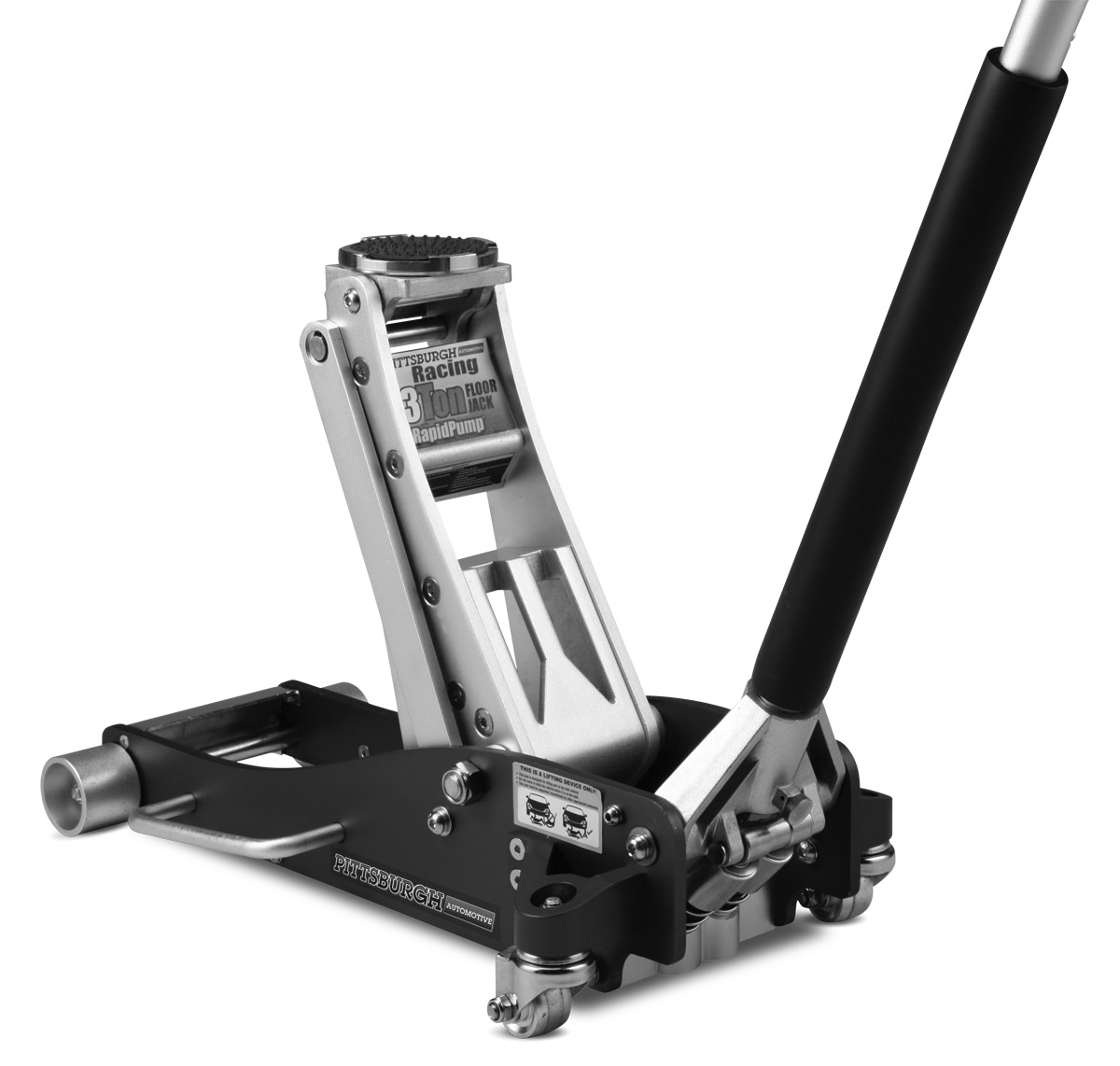
2 Table of contents Safety... Setup... 3 Operation... 4 Maintenance... 6 Parts Lists and Assembly Diagrams... 8 Warranty... SAFETy SETUp OpERATION MAINTENANcE WARNING SyMBOLS AND DEFINITIONS This is the safety alert symbol. It is used to alert you to potential personal injury hazards. Obey all safety messages that follow this symbol to avoid possible injury or death. Indicates a hazardous situation which, if not avoided, will result in death or serious injury. Indicates a hazardous situation which, if not avoided, could result in death or serious injury. Indicates a hazardous situation which, if not avoided, could result in minor or moderate injury. Addresses practices not related to personal injury. IMpORTANT SAFETy INFORMATION Floor Jack Safety Warnings. Study, understand, and follow all instructions before operating this device.. Do not exceed rated capacity. 3. Use only on hard, level surfaces. 4. Lifting device only. Immediately after lifting, support the vehicle with appropriate means. 5. Do not move or dolly the vehicle while on the jack. 6. Failure to heed these markings may result in personal injury and/or property damage. 7. Lift only areas of the vehicle as specified by the vehicle manufacturer. 8. No alterations shall be made to this product. 9. Never work on, under or around a load supported only by this device. 0. Do not adjust safety valve.. Wear ANSI-approved safety goggles and heavy-duty work gloves during use.. Keep clear of load while lifting and lowering. 3. Lower load slowly. 4. Apply parking brake and chock tires before lifting vehicle. 5. Lift vehicle only at manufacturer recommended locations. 6. Inspect before every use; do not use if s are loose or damaged. 7. Do not use for aircraft purposes. 8. The warnings, precautions, and instructions discussed in this manual cannot cover all possible conditions and situations that may occur. The operator must understand that common sense and caution are factors, which cannot be built into this product, but must be supplied by the operator. 9. The brass components of this product contain lead, a chemical known to the State of California to cause cancer, birth defects (or other reproductive harm). (California Health & Safety code 549.5, et seq.) IMpORTANT! Before first use: Check hydraulic oil level and fill to /4 below the fill port as needed as stated on page 4. Thoroughly test the Jack for proper operation. If it does not work properly, bleed air from its hydraulic system as stated on page 4. SAVE THESE INSTRUcTIONS. Page For technical questions, please call Item

3 Setup - Before Use: Read the ENTIRE IMpORTANT SAFETy y INFORMATION section at the beginning of this manual including all text under subheadings therein before set up or use of this product. SAFETy Note: For additional information regarding the s listed in the following pages, refer to Parts Lists and Assembly Diagrams on page 8. Functions Saddle Pad Saddle Handle Oil Fill Screw (Not Shown) Lifting Arm SETUp Handle Socket Carry Handle Rear Caster Safety Valve Cover Screw. Do not open or adjust. Fill Screw Screw Fill Screw 6805 / Safety Valve Cover Screw. Do not open or adjust Fill Screw Figure B: Hydraulic Unit Item For technical questions, please call Page 3 MAINTENANcE Cover Screw for Safety Valve. Do not open or adjust. OpERATION Figure A
4 Operating Instructions Read the ENTIRE IMpORTANT SAFETy INFORMATION section at the beginning of this manual including all text under subheadings therein before set up or use of this product. SAFETy SETUp OpERATION MAINTENANcE Tool Set Up Attaching the Handle caution! The Handle may contain a spring under tension. Wear ANSI-approved safety goggles before loosening or removing Handle. Remove Handle carefully.. Fasten the Upper Handle to the Lower Handle.. Loosen the Set Screw and insert the assembled Handle into the Handle Socket. Bleeding. Loosen the Fill Screw.. Turn the Handle counterclockwise to open the Release Valve. Adding Oil (Models 6805/68053). Remove Fill Screw and Screw simultaneously, see Figure B: Hydraulic Unit.. Add high grade hydraulic fluid into the Fill Screw slowly until the oil reaches the top of the oil fill hole. Adding Oil (Models 68054/6805). Remove the Fill Screw.. Add high grade hydraulic fluid into the Fill Screw slowly until the oil reaches the top of the oil fill hole. 3. Tighten the Set Screw. 3. Pump the Handle up and down quickly several times to purge air from the system. 4. Tighten the Fill Screw. Note: Do not touch the Handle when adding the hydraulic oil. 3. Replace the Fill Screw and Screw. Note: Do not touch the Handle when adding the hydraulic oil. 3. Replace the Fill Screw. Page 4 For technical questions, please call Item
5 General Operating Instructions Lifting park vehicle on a flat, level, solid, surface safely away from oncoming traffic. Turn off the vehicle s engine. place the vehicle s transmission in park (if automatic) or in its lowest gear (if manual). Set the vehicle s emergency brake. Then, chock the wheels that are not being lifted.. Turn the Handle counterclockwise to lower the Jack. Once the Jack is fully lowered, turn the Handle firmly clockwise to close it.. Carefully position the Saddle of the Jack under the vehicle manufacturer s recommended lifting point. (See vehicle manufacturer s owner s manual for location of frame lifting point.) 3. Pump the Handle until the top of the Jack s Saddle has nearly reached the vehicle lifting point. Position the Saddle directly under the vehicle s lifting point. 4. To lift the vehicle, pump the Handle of the Jack. Use smooth, full strokes. 5. Once the vehicle is raised, slide a jack stand of appropriate capacity (not included) under a proper lifting point referred to in the vehicle owner s manual. Always use two jack stands, position them at the same point on each side of the vehicle. Lowering. Carefully remove all tools, s, etc. from under the vehicle.. Position the Saddle under the lifting point. Turn the Handle firmly clockwise and raise load high enough to clear the jack stands, then carefully remove jack stands. 3. Slowly turn the Handle counterclockwise (never more than / full turn) to lower the vehicle onto the ground. WARNING! The rated capacity of jack stands is per pair, not the individual capacities combined unless specifically noted on the product by the jack stand manufacturer. Do not exceed rated jack stand capacity. Ensure that the vehicle support points are fully seated in the saddle of both jack stands. Use a matched pair of jack stands per vehicle to support one end only. Failure to do so may result in the load suddenly falling, which may cause personal injury and/or property damage. 6. Center the vehicle s lifting point(s) on the saddle of the jack stand(s). Set the jack stand(s) to the same height according to the manufacturer s instructions, making sure that they lock securely into position. 7. Slowly turn the Handle counterclockwise to lower the vehicle onto the saddle(s) of the jack stand(s). Then, turn the Handle firmly clockwise to close it. 4. Lower the Jack completely. Then, store in a safe, dry location out of reach of children. 5. To prevent accidents, turn off the tool and disconnect its power supply after use. Clean, then store the tool indoors out of children s reach. SAFETy MAINTENANcE OpERATION SETUp Item For technical questions, please call Page 5
6 Maintenance and Servicing procedures not specifically explained in this manual must be performed only by a qualified technician. SAFETy SETUp OpERATION MAINTENANcE TO prevent SERIOUS INJURy FROM TOOL FAILURE: Do not use damaged equipment. If abnormal noise or vibration occurs, have the problem corrected before further use. cleaning, Maintenance, and Lubrication. Before each use, inspect the general condition of the Jack. Check for broken, cracked, or bent s, loose or missing s, and any condition that may affect the proper operation of the product. If a problem occurs, have the problem corrected before further use. Do not use damaged equipment.. Before each use, thoroughly test the Jack for proper operation prior to its actual use. If the Jack appears not to be working properly, follow Bleeding instructions on page Change the hydraulic oil at least once every three years: A. With the Jack fully lowered, remove the Oil Filler Plug on the side of the Housing. B. Tip the Jack to allow the old hydraulic oil to drain out of the Housing completely, and dispose of the old hydraulic oil in accordance with local regulations. C. With the Jack upright, completely fill the Housing with a high quality hydraulic oil (not included) until the oil is /4 below the fill hole. D. Open the valve by turning the Handle counterclockwise and pump the Handle to bleed air from the system. E. Recheck oil level and re-fill as needed. F. Reinstall the Oil Filler Plug. 7. Wipe dry with a clean cloth. Then, store the Jack in a safe, dry location out of reach of children and other non-authorized people. Page 6 For technical questions, please call Item
7 Troubleshooting TO prevent SERIOUS INJURy : Use caution when troubleshooting a malfunctioning jack. Stay well clear of the supported load. completely resolve all problems before use. If the solutions presented in the Troubleshooting guide do not solve the problem, have a qualified technician inspect and repair the jack before use. After the jack is repaired: Test it carefully without a load by raising and lowering it fully, checking for proper operation, BEFORE RETURNING THE JAcK TO OpERATION. DO NOT USE A DAMAGED OR MALFUNcTIONING JAcK! SAFETy possible SyMpTOMS Jack will not lift at its weight capacity X Saddle lowers under load X Pump stroke feels spongy Saddle will not lift all the way Handle moves up when jack is under load Oil leaking from filler plug probable SOLUTION (Make certain that the jack is not supporting a load while attempting a solution.) Check that Release Valve is fully closed. Bleed air from the system. X X X X X X X Valves may be blocked and may not close fully. To flush the valves:. Lower the Saddle and securely close the Release Valve.. Manually lift the saddle several inches. 3. Open the release valve and force the saddle down as quickly as possible. Jack may be low on oil. Check the oil level and refill if needed. Jack may require bleeding - see instructions on page Bleeding on page 4. Unit may have too much hydraulic oil inside, check fluid level and adjust if needed. MAINTENANcE OpERATION SETUp Item For technical questions, please call Page 7
8 s Lists and Assembly Diagrams 6805 s List and Assembly Diagram SAFETy SETUp OpERATION MAINTENANcE Saddle Pad Saddle Screw 3 Saddle 4 Saddle Base 5 Shaft 6 Retaining Ring (8) 7 Front Wheel Axle 8 Side Plate 9 Bushing 0 Front Wheel Washer Nut (M) 4 3 Carrying Handle 4 Screw (M6X5) 5 Washer 6 6 Screw (M8X5) 4 7 Radius Linkage 8 Screw 9 Tie Rod Saddle Shaft Tie Block Lift Arm Side Plate 3 Bolt 4 Washer (0) 5 Washer (0) 6 Screw (M0X5) 8 7 Nut M8 8 Screw (M0X35) 6 9 Screw (M8X0) 30 Washer (8) 3 Screw (M0X0) 3 Rear Caster 33 Rear Caster Base 34 Washer (0) 35 Screw (M6X5) 36 Spring 37 Retaining Ring (9) 38 Short Linkage Hydraulic Unit 40 Handle Bumper 4 Upper Handle 4 Lower Handle 43 Set Screw 44 Retaining Ring () 45 Socket Roller 46 Socket Roller Shaft 47 Handle Socket 48 Bolt 49 Tie Rod 50 Lift Arm Shaft 5 Rubber Bumper 5 Pin (4X45) 53 Hydraulic Adaptor 54 Bolt 55 Block 56 Block Shaft Page 8 For technical questions, please call Item
9 6805 s List and Assembly Diagram Saddle Pad Saddle Screw 3 Saddle 4 Saddle Base 5 Lift Arm 6 Radius Linkage 7 Front Wheel 8 Carrying Handle 9 Side Plate 0 Rear Caster Nut (M) 4 Handle Socket 3 Set Screw 4 Upper Handle 5 Lower Handle 6 Handle Bumper 7 Tie Rod 8 Hydraulic Unit SAFETy MAINTENANcE OpERATION SETUp Item For technical questions, please call Page 9
10 68053 s List and Assembly Diagram SAFETy SETUp OpERATION MAINTENANcE Saddle Pad Saddle Screw 3 Saddle 4 Saddle Base 5 Shaft 6 Shaft 7 Retaining Ring (3) 8 Front Wheel Axle 9 Side Plate 0 Washer (M0) 8 Screw (M0X0) Carrying Handle 3 Screw (M6X0) 4 Radius Linkage 5 Front Wheel Screw (M8X6) 6 7 Lift Arm 8 Bolt 9 Washer (M8) 0 0 Washer (M8) 4 Nut (M6) Screw (M6X0) 3 Washer (M6) 4 Screw (M0X5) 6 5 Rear Caster 6 Rear Caster Base 7 Nut (M0) 8 Handle Yoke Shaft 9 Clip 30 Spring Retaining Ring (9) 3 Power Unit Adaptor 33 Hydraulic Unit 34 Pin (M4X6) 35 Yoke Roller Shaft 36 Yoke Roller 37 Retaining Ring () 38 Set Screw 39 Lower Handle 40 Upper Handle 4 Handle Bumper 4 Tie Rod 43 Gasket 44 Screw (M8X0) Page 0 For technical questions, please call Item
11 68054 s List and Assembly Diagram Screw (M0X0) 8 Washer (0) 8 3 Washer (0) 4 4 Side Plate 5 Carrying Handle 6 Front Wheel Shaft 7 Screw (M8X0) 4 8 Radius Linkage 9 Lift Arm 0 Front Wheel Retaining Ring (6) Bush 3 Shaft 4 Saddle Base Shaft 5 Saddle Base 6 Saddle Plate Saddle 8 Saddle Bolt 9 Saddle Pad 0 Washer (8) Washer (8) Screw (M8X0) 3 Nut (M6) 4 Handle Socket 5 Retaining Ring () 6 Set Screw 7 Socket Roller 8 Socket Roller Shaft 9 Nut (M) 30 Rear Caster Base 3 Rear Caster 3 Retaining Ring (9) Linkage Plate 34 Pin (4X6) 35 Hydraulic Adaptor 36 Hydraulic Unit 37 Yoke Bolt 38 Gasket 39 Tie Rod 40 Lift Arm Shaft 4 Bolt 4 Screw 43 Clip 44 Spring 45 Lower Handle 46 Upper Handle 47 Handle Bumper SAFETy MAINTENANcE OpERATION SETUp Item For technical questions, please call Page
12 Record product s Serial Number Here: Note: If product has no serial number, record month and year of purchase instead. Note: Some s are listed and shown for illustration purposes only, and are not available individually as replacement s. please READ THE FOLLOWING carefullyly THE MANUFACTURER AND/OR DISTRIBUTOR HAS PROVIDED THE PARTS LIST AND ASSEMBLY DIAGRAM IN THIS MANUAL AS A REFERENCE TOOL ONLY. NEITHER THE MANUFACTURER OR DISTRIBUTOR MAKES ANY REPRESENTATION OR WARRANTY OF ANY KIND TO THE BUYER THAT HE OR SHE IS QUALIFIED TO MAKE ANY REPAIRS TO THE PRODUCT, OR THAT HE OR SHE IS QUALIFIED TO REPLACE ANY PARTS OF THE PRODUCT. IN FACT, THE MANUFACTURER AND/OR DISTRIBUTOR EXPRESSLY STATES THAT ALL REPAIRS AND PARTS REPLACEMENTS SHOULD BE UNDERTAKEN BY CERTIFIED AND LICENSED TECHNICIANS, AND NOT BY THE BUYER. THE BUYER ASSUMES ALL RISK AND LIABILITY ARISING OUT OF HIS OR HER REPAIRS TO THE ORIGINAL PRODUCT OR REPLACEMENT PARTS THERETO, OR ARISING OUT OF HIS OR HER INSTALLATION OF REPLACEMENT PARTS THERETO. Limited 90 Day Warranty Harbor Freight Tools Co. makes every effort to assure that its products meet high quality and durability standards, and warrants to the original purchaser that this product is free from defects in materials and workmanship for the period of 90 days from the date of purchase. This warranty does not apply to damage due directly or indirectly, to misuse, abuse, negligence or accidents, repairs or alterations outside our facilities, criminal activity, improper installation, normal wear and tear, or to lack of maintenance. We shall in no event be liable for death, injuries to persons or property, or for incidental, contingent, special or consequential damages arising from the use of our product. Some states do not allow the exclusion or limitation of incidental or consequential damages, so the above limitation of exclusion may not apply to you. THIS WARRANTY IS EXPRESSLY IN LIEU OF ALL OTHER WARRANTIES, EXPRESS OR IMPLIED, INCLUDING THE WARRANTIES OF MERCHANTABILITY AND FITNESS. To take advantage of this warranty, the product or must be returned to us with transportation charges prepaid. Proof of purchase date and an explanation of the complaint must accompany the merchandise. If our inspection verifies the defect, we will either repair or replace the product at our election or we may elect to refund the purchase price if we cannot readily and quickly provide you with a replacement. We will return repaired products at our expense, but if we determine there is no defect, or that the defect resulted from causes not within the scope of our warranty, then you must bear the cost of returning the product. This warranty gives you specific legal rights and you may also have other rights which vary from state to state. 349 Mission Oaks Blvd. PO Box 6009 Camarillo, CA 930 (800)
Table of Contents WARNING SYMBOLS AND DEFINITIONS
 Table of Contents SAFETY INSTALLATION OPERATION MAINTENANCE Safety... 2 Specifications... 4 Installation... 5 Operation... 8 WARNING SYMBOLS AND DEFINITIONS Maintenance... 9 Parts List and Assembly Diagram...
Instructions and precautions. Fork Height. Visit our website at: http://www.harborfreight.com
 Pallet Jack Item 68760 / 68761 Instructions and precautions Specifications Capacity Control Lever Fork Height Fork Length Fork Width Maximum Minimum Width over Forks Steering Wheel Dia. 2-1/2 Ton (5,000
HYDRAULIC TABLE CART
 Owner s Manual & Safety Instructions Save This Manual Keep this manual for the safety warnings and precautions, assembly, operating, inspection, maintenance and cleaning procedures. Write the product s
PALLET JACK - 2.5 TON
 PALLET JACK - 2.5 TON 39939 SET UP AND OPERATING INSTRUCTIONS Visit our website at: http://www.harborfreight.com Read this material before using this product. Failure to do so can result in serious injury.
1 Ton Telescoping Gantry Crane
 1 Ton Telescoping Gantry Crane 41188 Gantry Crane Read this material before using this product. Failure to do so can result in serious injury. SAVE THIS MANUAL. When unpacking, make sure that the product
Hydraulic Punch Driver Kit
 Hydraulic Punch Driver Kit Item 96718 Instructions and precautions Visit our website at: http://www.harborfreight.com Read this material before using this product. Failure to do so can result in serious
OAK WORKBENCH WITH 2 DRAWERS
 OAK WORKBENCH WITH 2 DRAWERS Model 93991 ASSEMBLY Instructions Visit our website at: http://www.harborfreight.com Read this material before using this product. Failure to do so can result in serious injury.
Owner s Manual & Safety Instructions
 Owner s Manual & Safety Instructions Save This Manual Keep this manual for the safety warnings and precautions, assembly, operating, inspection, maintenance and cleaning procedures. Write the product s
Owner s Manual & Safety Instructions
 Owner s Manual & Safety Instructions Save This Manual Keep this manual for the safety warnings and precautions, assembly, operating, inspection, maintenance and cleaning procedures. Write the product s
Hydraulic Transmission Jacks Operating Instructions & Parts Manual
 Blackhawk Automotive is a Licensed Trade Mark Made by SFA Companies, Kansas City, MO Hydraulic Transmission Jacks Operating Instructions & Parts Manual Model BH7011 BH7210 Capacity 1/2 Ton 1 Ton SFA Companies
Digital Fingerprint safe
 Digital Fingerprint safe Model 96846 Operation Instructions Diagrams within this manual may not be drawn proportionally. Due to continuing improvements, actual product may differ slightly from the product
Strut Spring Compressor
 Strut Spring Compressor Item 43753 Read this material before using this product. Failure to do so can result in serious injury. SAVE THIS MANUAL. When unpacking, make sure that the product is intact and
Air vacuum pump with r134a & r12/22
 Air vacuum pump with r134a & r12/22 Model 96677 Set up And Operating Instructions To prevent explosion, serious injury, and death: Service of air conditioning systems must be done only by trained and experienced
Flat Bottom Long Ram Hydraulic Jack
 Flat Bottom Long Ram Hydraulic Jack 3 Ton 8 Ton 36468 36469 ASSEMBLY & OPERATING INSTRUCTIONS 349 Mission Oaks Blvd., Camarillo, CA 930 Visit our Web site at http://www.harborfreight.com TO PREVENT SERIOUS
Mini-led spotlight with magnetic base
 Mini-led spotlight with magnetic base Model 95799 Assembly And Operation Instructions Due to continuing improvements, actual product may differ slightly from the product described herein. 3491 Mission
PNEUMATIC PLANISHING HAMMER
 PNEUMATIC PLANISHING HAMMER 94847 ASSEMBLY AND OPERATING INSTRUCTIONS Due to continuing improvements, actual product may differ slightly from the product described herein. Distributed Exclusively by Harbor
8 ton air/hydraulic long ram jack
 8 ton air/hydraulic long ram jack Model 94562 Set up and Operating Instructions Visit our website at: http://www.harborfreight.com Read this material before using this product. Failure to do so can result
PAINT SPRAY GUN WASHER
 PAINT SPRAY GUN WASHER 94996 ASSEMBLY AND OPERATING INSTRUCTIONS Visit our website at: http://www.harborfreight.com Read this material before using this product. Failure to do so can result in serious
FJ2. 2 Ton Trolley Floor Jack Assembly & Operating Instructions
 FJ2 2 Ton Trolley Floor Jack Assembly & Operating Instructions READ ALL INSTRUCTIONS AND WARNINGS BEFORE USING THIS PRODUCT. This manual provides important information on proper operation & maintenance.
Owner s Manual & Safety Instructions
 Owner s Manual & Safety Instructions Save This Manual Keep this manual for the safety warnings and precautions, assembly, operating, inspection, maintenance and cleaning procedures. Write the product s
1 / 4 IN. FFL x 4 FT. 9 IN. 1 / 2 IN. ACME x 4 FT. 9 IN. Gauge Accuracy +/-2% Set includes Quick Disconnect Valves
 Specifications Blue (Low) Gauge 0-120 PSI Blue Hose 1 / 4 IN. FFL x 4 FT. 9 IN. Red (High) Gauge 0-500 PSI Red Hose 1 / 4 IN. FFL x 4 FT. 9 IN. Yellow Hose 1 / 2 IN. ACME x 4 FT. 9 IN. Gauge Accuracy +/-2%
tire inflator with pressure gauge
 tire inflator with pressure gauge Model 95583 Assembly And Operation Instructions Due to continuing improvements, actual product may differ slightly from the product described herein. 3491 Mission Oaks
Owner s Manual & Safety Instructions
 Owner s Manual & Safety Instructions Save This Manual Keep this manual for the safety warnings and precautions, assembly, operating, inspection, maintenance and cleaning procedures. Write the product s
HYDRAULIC TABLE CART 500-LB.
 HYDRAULIC TABLE CART 500-LB. OWNER S MANUAL WARNING: Read carefully and understand all MACHINE ADJUSTMENT AND OPERATION INSTRUCTIONS before operating. Failure to follow the safety rules and other basic
lamp post light Set up and Operating Instructions
 lamp post light 66240 Set up and Operating Instructions Distributed exclusively by Harbor Freight Tools. 3491 Mission Oaks Blvd., Camarillo, CA 93011 Visit our website at: http://www.harborfreight.com
PEDAL CAR - GO CART ASSEMBLY & OPERATING INSTRUCTIONS
 PEDAL CAR - GO CART 42822 ASSEMBLY & OPERATING INSTRUCTIONS 3491 Mission Oaks Blvd., Camarillo, CA 93011 Visit our Web site at: http://www.harborfreight.com Copyright 2000 by Harbor Freight Tools. All
HYDRAULIC LIFT TABLE CART 2200-LB.
 HYDRAULIC LIFT TABLE CART 2200-LB. OWNER S MANUAL WARNING: Read carefully and understand all MACHINE ADJUSTMENT AND OPERATION INSTRUCTIONS before operating. Failure to follow the safety rules and other
staple gun with 5/16 Long staples
 staple gun with 5/16 Long staples Model 95718 Assembly And Operation Instructions Due to continuing improvements, actual product may differ slightly from the product described herein. 3491 Mission Oaks
3/4 PIPE CLAMP WITH STAND
 3/4 PIPE CLAMP WITH STAND Model 94053 ASSEMBLY AND OPERATING INSTRUCTIONS (3/4 DIAMETER PIPE NOT INCLUDED.) 3491 Mission Oaks Blvd., Camarillo, CA 93011 Visit our Web site at: http://www.harborfreight.com
TURN TABLES 1.5 TON CAPACITY / 2 PC. Model 45742
 TURN TABLES 1.5 TON CAPACITY / 2 PC. Model 45742 OPERATING INFORMATION 3491 Mission Oaks Blvd., Camarillo, CA 93011 Visit our Web site at http://www.harborfreight.com Copyright 2001 by Harbor Freight Tools.
ROUTER TABLE INSERT ASSEMBLY AND OPERATING INSTRUCTIONS
 ROUTER TABLE INSERT 94331 ASSEMBLY AND OPERATING INSTRUCTIONS 3491 Mission Oaks Blvd., Camarillo, CA 93011 Visit our Web site at http://www.harborfreight.com Copyright 2006 by Harbor Freight Tools. All
Hand Held Metal Detector
 Hand Held Metal Detector Model 97245 Set up And Operating Instructions Diagrams within this manual may not be drawn proportionally. Due to continuing improvements, actual product may differ slightly from
MODEL G300 BRAKE BLEEDER
 MODEL G300 BRAKE BLEEDER Installation, Operation & Repair Parts Information Branick Industries, Inc. 4245 Main Avenue P.O. Box 1937 Fargo, North Dakota 58103 REV060616 P/N: 81-0035G 1 THIS PAGE INTENTIONALLY
Seven function digital multimeter
 Seven function digital multimeter 98025 Set up And Operating Instructions Distributed exclusively by Harbor Freight Tools. 3491 Mission Oaks Blvd., Camarillo, CA 93011 Visit our website at: http://www.harborfreight.com
TITAN 13 x 2 ½ BRAKES
 INSTALLATION INSTRUCTION AND SERVICE MANUAL Actuator/Trailer Dealer - Please provide these instructions to the consumer. Consumer - Read and follow these instructions. Keep them with the trailer for future
INSTRUCTIONS AND PARTS LIST FOR MODEL 70H & 75H HAND-OPERATED HYDRAULIC PRESS
 INSTRUCTIONS AND PARTS LIST FOR MODEL 70H & 75H HAND-OPERATED HYDRAULIC PRESS SETTING UP THE PRESS FOR OPERATION For shipping convenience, the gauge, pump handle, hoist crank, screw nose and base angles
DUST COLLECTOR 70 GALLON, 2 HP
 DUST COLLECTOR 70 GALLON, 2 HP Model 45378 ASSEMBLY AND OPERATING INSTRUCTIONS 3491 Mission Oaks Blvd., Camarillo, CA 93011 Visit our Web site at http://www.harborfreight.com Copyright 2001 by Harbor Freight
Cylinder Leak- Down Tester
 Cylinder Leak- Down Tester Item 94190 INSTRUCTIONS AND PRECAUTIONS Visit our website at: http://www.harborfreight.com When unpacking, make sure that the product is intact and undamaged. If any parts are
15GAL STEEL OIL DRAIN WITH 110V PUMP
 15GAL STEEL OIL DRAIN WITH 110V PUMP OWNER S MANUAL WARNING: Read carefully and understand all ASSEMBLY AND OPERATION INSTRUCTIONS before operating. Failure to follow the safety rules and other basic safety
Air/Hydraulic Bottle Jack
 Air/Hydraulic Bottle Jack Specifications 94487 12-Ton Air/Hydraulic Jack Weight Capacity 12 Tons (24,000 lb.) Maximum Height 20-1/8 IN. (with screw cap extended) Minimum Height 10-1/4 IN. Maximum Air Pressure
SE-100-1, SE-200-1, SE-500-1, and SE-1000-1 AIR CHAMP PRODUCTS. User Manual SE BRAKE MODELS: (i) MTY (81) 83 54 10 18 ventas@industrialmagza.
 MTY (81) 83 54 10 18 ventas@industrialmagza.") AIR CHAMP PRODUCTS User Manual SE BRAKE MODELS: SE-00-, SE-200-, SE-500-, and SE-000- (i) FORM NO. L-20084-E-040 In accordance with Nexen s established policy of constant product improvement, the specifications
AIR CHAMP PRODUCTS User Manual SE BRAKE MODELS: SE-00-, SE-200-, SE-500-, and SE-000- (i) FORM NO. L-20084-E-040 In accordance with Nexen s established policy of constant product improvement, the specifications
AIR HYDRAULIC RIVETER
 AIR HYDRAULIC RIVETER Model 93458 Set up And Operating Instructions Distributed exclusively by Harbor Freight Tools. 3491 Mission Oaks Blvd., Camarillo, CA 93011 Visit our website at: http://www.harborfreight.com
1000-LB. TRAILER JACK OWNER S MANUAL
 1000-LB. TRAILER JACK OWNER S MANUAL WARNING: Read carefully and understand all INSTRUCTIONS before operating. Failure to follow the safety rules and other basic safety precautions may result in serious
Pet hair clipper. Model 96822. Diagrams within this manual may not be drawn proportionally.
 Pet hair clipper Model 96822 Cleaning And Operation Instructions Diagrams within this manual may not be drawn proportionally. Due to continuing improvements, actual product may differ slightly from the
Table of Contents. Safety... 3 Specifications... 4 Assembly... 5. Maintenance... 29 Warranty... 32 Parts Lists... 30
 Table of Contents Safety... 3 Specifications... 4 Assembly... 5 Maintenance... 29 Warranty... 32 Parts Lists... 30 WARNING SYMBOLS AND DEFINITIONS This is the safety alert symbol. It is used to alert you
1/3 HP Submersible Sump Pump with Vertical Float Switch
 1/3 HP Submersible Sump with Vertical Float Switch Item 68476 Specifications Float Switch Operation Height 7.1 IN. ON / 2.8 IN. OFF Electrical Requirements 120V~ / 60Hz / 7.6A Power Length Maximum Capacity
Owner s Manual & Safety Instructions
 Owner s Manual & Safety Instructions Save This Manual Keep this manual for the safety warnings and precautions, assembly, operating, inspection, maintenance and cleaning procedures. Write the product s
Pallet Jack. OWNER S MANUAL Model MH1230. Important Safety Instructions Assembly Instructions Parts and Hardware Identification
 OWNER S MANUAL Model MH1230 Important Safety Instructions Assembly Instructions Parts and Hardware Identification Pallet Jack CAUTION: Read, understand and follow ALL instructions before using this product
Owner s Manual & Safety Instructions
 Owner s Manual & Safety Instructions Save This Manual Keep this manual for the safety warnings and precautions, assembly, operating, inspection, maintenance and cleaning procedures. Write the product s
1 TON FOLDING CRANE CFC1000
 1 TON FOLDING CRANE CFC1000 OPERATION &MAINTENANCE INSTRUCTIONS 0401 SPECIFICATIONS MAXIMUM SAFE WORKING LOADS (kg) 1 2 3 4 1000 750 500 250 MAXIMUM LIFT HEIGHT - 1920mm HYDRAULIC RAM OIL CAPACITY - 450CC
Visit our website at: http://www.harborfreight.com. Email our technical support at: tech@harborfreight.com
 2.5 CFM Vacuum Pump Item 98076 Danger To prevent explosion, serious injury, and death: Service of air conditioning systems must be done only by trained and experienced technician to avoid overfilling.
8-TON BOTTLE JACK OWNER S MANUAL
 8-TON BOTTLE JACK OWNER S MANUAL WARNING: Read carefully and understand all ASSEMBLY AND OPERATION INSTRUCTIONS before operating. Failure to follow the safety rules and other basic safety precautions may
Thank You For Choosing. INSTALLATION INSTRUCTIONS Portal Gear Hubs Polaris RZR 800. (installation performed on 60 Model) (Right) (Left)
 (Right) (Left)") 740B Clifty Drive Madison, Indiana 47250 812-574-7777 INSTALLATION INSTRUCTIONS Portal Gear Hubs Polaris RZR 800 A (installation performed on 60 Model) Item Description Qty A Rotor 4 B Gear Box, L 2 C
740B Clifty Drive Madison, Indiana 47250 812-574-7777 INSTALLATION INSTRUCTIONS Portal Gear Hubs Polaris RZR 800 A (installation performed on 60 Model) Item Description Qty A Rotor 4 B Gear Box, L 2 C
Owner s Manual & Safety Instructions
 Owner s Manual & Safety Instructions Save This Manual Keep this manual for the safety warnings and precautions, assembly, operating, inspection, maintenance and cleaning procedures. Write the product s
Installation manual. 1.75 front leveling kit. 2011 Dodge Durango 2011-2014 Jeep Grand Cherokee. Part # 42006. Part # 42006
 Installation manual 1.75 front leveling kit 2011 Dodge Durango 2011-2014 Jeep Grand Cherokee Part # 42006 sj02282011rev.01 Part # 42006 2011-2014 Dodge Durango 2011 Jeep Grand Cherokee 1.75 front leveling
LIFT N RACK PRO OPERATING & INSTALLATION GUIDE 5500 Lb. LIFT CAPACITY
 LIFT N RACK PRO OPERATING & INSTALLATION GUIDE 5500 Lb. LIFT CAPACITY IMPORTANT: READ THIS MANUAL BEFORE IN-STALLING, OPERATING OR MAINTAINING YOUR LIFT. Chassis Liner Company Sales Office Toll Free: 800-242-2448
Thank You For Choosing. INSTALLATION INSTRUCTIONS Portal Gear Hubs Polaris RZR XP 900 Crew. (Right) (Left)
 (Left)") 740B Clifty Drive Madison, Indiana 47250 812-574-7777 INSTALLATION INSTRUCTIONS Portal Gear Hubs Polaris RZR XP 900 Crew A Item Description Qty A Rotor 4 B Gear Box, L 2 C Gear Box, R 2 D Gasket 4 E Cap
740B Clifty Drive Madison, Indiana 47250 812-574-7777 INSTALLATION INSTRUCTIONS Portal Gear Hubs Polaris RZR XP 900 Crew A Item Description Qty A Rotor 4 B Gear Box, L 2 C Gear Box, R 2 D Gasket 4 E Cap
Service Manual Rol-Lift
 R 2000 Service Manual Rol-Lift Series: T and E Developed by Generic Parts Service This manual is intended for basic service and maintenance of the Rol-Lift pallet jack. The pallet jacks you are servicing
SAFETY & OPERATING INSTRUCTIONS
 SAFETY & OPERATING INSTRUCTIONS EDLUND TOMATO LASER, Models ETL -316, -140 & -380 READ AND UNDERSTAND THIS MANUAL AND ALL INSTRUCTIONS BEFORE OPERATING THIS SLICER. 159 Industrial Parkway, Burlington,
Diesel Engine Compression Tester
 Diesel Engine Compression Tester Item 93644 Read this material before using this product. Failure to do so can result in serious injury. SAVE THIS MANUAL. When unpacking, make sure that the product is
RZ Guardrail System Installation Manual
 TM RZ Guardrail System Installation Manual RZ Guardrail System Compliance is based on OSHA standards: (Standards - 29 CFR) 1910.23 (e) and (Standards - 29 CFR) 1926.502 (b) Failure to read, understand
MP-4V Heavy Duty Riveter / 39048
 MP-4V Heavy Duty Riveter / 39048 This newly designed heavy-duty air/hydraulic riveter is ergonomically designed with the professional in mind. The light weight 3.7 lbs. well balanced MP-4V includes a Vacuum
POWER GEAR SLIDE OUT MANUAL
 POWER GEAR SLIDE OUT MANUAL Operation Guide FLUSH FLOOR SLIDE OUT SYSTEM FOR AMERICAN COACH PRODUCTS 82 S0220 01 Rev. 1 AMERICAN COACH SLIDE OUT MANUAL FLUSH FLOOR SYSTEM TABLE OF CONTENTS SECTION PAGE
Owner s Manual Read and keep this manual. Patents World Wide
 Owner s Manual Read and keep this manual. Patents World Wide S & S Industries, Inc., Sarasota, FL, USA www.trail-gator.com Copyright 2008 All Rights Reserved The following manual is provided to assist
WARNING TO END USER, INSTALLER AND SELLER OF THIS PART!
 WARNING TO END USER, INSTALLER AND SELLER OF THIS PART! By installing this part you are accepting full responsibility and liability for proper wheel and tire fitment after installation. It is the installer
SELF-STEERING AXLE TABLE OF CONTENTS
 SELF-STEERING AXLE TABLE OF CONTENTS Section 1 - Introduction Section 2 - Pre-Installation Check List Section 3 - Ride Height Adjustments Section 4 - Suspension Mount Section 5 - Axle Mount Section 6 -
Calvert USA, Inc. Attic Stairs
 Calvert USA, Inc. Attic Stairs Instructions for installation of vertical opening access stairs Model numbers: 7035 through 7047 Calvert USA, Inc., P.O. Box 841, Solomons, MD 20688, Tel. (410) 286-1430,
GM DURAMAX LMM 09-10 Fuel Pickup Kit Installation Guide
 Pacific Performance Engineering, Inc. www.ppediesel.com GM DURAMAX LMM 09-10 Fuel Pickup Kit Installation Guide Technical Support (714) 985-4825 Rev: 3/30/11 v5 DISCLAIMER OF LIABILITY This agreement sets
MEASURING WHEEL ALIGNMENT
 MEASURING WHEEL ALIGNMENT 2003-04 WHEEL ALIGNMENT Specifications & Procedures - Hummer - H2 Steering and vibration complaints are not always the result of improper alignment. One possible cause is wheel
Electric Hoist 44006
 440 lb./ 880 lb. Electric Hoist 44006 SET UP AND OPERATING INSTRUCTIONS Distributed exclusively by Harbor Freight Tools. 3491 Mission Oaks Blvd., Camarillo, CA 93011 Visit our website at: http://www.harborfreight.com
cbperformance.com Please read this entire brochure prior to installing your CB Performance Products MAGNASPARK II distributor.
 - Easy -wire installation with no external spark box necessary, but can be used with one. - Precision CNC machining and hand assembled construction. This is a premium product. - Accurate super hot spark
Class 5 to 7 Truck and Bus Hydraulic Brake System
 Class 5 to 7 Truck and Bus Hydraulic Brake System Diagnostic Guide 1st Edition * 5+0 Important Service tes The information in this publication was current at the time of printing. The information presented
Operating Instructions Manual. Hydraulic Transmission Jack, Telescopic
 Operating Instructions Manual Hydraulic Transmission Jack, Telescopic Model Capacity 4000C 000 lb. 400C (air option) 000 lb. Model 4000C! This is the safety alert symbol. It is used to alert you to potential
Mini Pallet Jack OWNER S MANUAL
 Mini Pallet Jack OWNER S MANUAL WARNING: Read carefully and understand all ASSEMBLY AND OPERATION INSTRUCTIONS before operating. Failure to follow the safety rules and other basic safety precautions may
SHOP PRESS ASSEMBLY INSTRUCTIONS
 SHOP PRESS ASSEMBLY INSTRUCTIONS 5250-50 Ton Manual Shop Press With Winch PRESS SPECIFICATIONS Sunex Part No. A B C D E F G H I 5250 74" 35" 29.75" 13" 6.75" 1.25" Y Y Y(2) A - Total Height B - Inside
Installation Instructions and Service Manual
 Installation Instructions and Service Manual Model 85, 85-3/4 & 85E Actuator* for Trailer Brakes 8,500 lbs. Capacity for use with -5/16 Hitch Balls Drum Brake Ready - Part #4736 Disc Brake Ready - Part
Operating Instructions and Parts Manual Arbor Press ½-, 1-, 2-, 3-, 5-Ton Model No. AP0-M, AP1-M, AP2-M, AP3-M, AP5-M
 Operating Instructions and Parts Manual Arbor Press ½-, 1-, 2-, 3-, 5-Ton Model No. AP0-M, AP1-M, AP2-M, AP3-M, AP5-M WALTER MEIER (Manufacturing) Inc. 427 New Sanford Road LaVergne, Tennessee 37086 Part
CHROME FRONT BRAKE MASTER CYLINDER KIT
 -J075 REV. 009-0-0 CHROME FRONT BRAKE MASTER CYLINDER KIT GENERAL Kit Number 5-99D, 5-99D Models These Chrome Master Cylinder Kits are designed to replace the original equipment front brake master cylinder
Owner s Manual DANDY LIFT. Model # Serial # Placed in Service. Southworth Products Corp
 Owner s Manual DANDY LIFT For model numbers UDL-50, UDL-50, UDA-350W, UDA-500 & UDA-800, this manual is for Serial number L-48493 and up, and for machines manufactured in September 0 and newer. For older
2011-14 F250 6 RADIUS ARM KIT
 92154000 Thank you for choosing Rough Country for your suspension needs. 2011-14 F250 6 RADIUS ARM KIT Rough Country recommends a certified technician installs this system. In addition to these instructions,
1 HP MINI DUST COLLECTOR
 1 HP MINI DUST COLLECTOR 31810 Set up and Operating Instructions Visit our website at: http://www.harborfreight.com Read this material before using this product. Failure to do so can result in serious
Failure to comply with the following cautions and warnings could cause equipment damage and personal injury.
 1.0 IMPORTANT RECEIVING INSTRUCTIONS Visually inspect all components for shipping damage. Shipping Damage is not covered by warranty. If shipping damage is found, notify carrier at once. The carrier is
3 WATT LED SPOTLIGHT Model No. SLM - 3801
 3 WATT LED SPOTLIGHT Model No. SLM - 3801 OWNER'S MANUAL Customer Service Tel: 1-800-268-3319 Superex Canada Ltd, Toronto,M2H 3B8 Made in China Table of Contents A). Important Safety Instructions B). Charging
TRACTOR QUICK HITCH CATEGORY I
 TRACTOR QUICK HITCH CATEGORY I Assembly, Operation & Parts Manual January 2005 Form: Quickhitch.PM7 SAFETY INFORMATION To avoid accident or injury, do not allow anyone to operate this equipment without
Unit: mm(in) Item Standard value Service limit Axle shaft run out - 0.2(0.008)
 Item Standard value Service limit Axle shaft run out - 0.2(0.008)") Rear Wheel/Brake/Suspension 13. Rear Wheel/Brake/Suspension Service Information 13-1 Troubleshooting 13-2 Rear Wheel 13-3 Rear Cushion 13-4 Rear Swing Arm 13-7 Service Information General Safety If the
Rear Wheel/Brake/Suspension 13. Rear Wheel/Brake/Suspension Service Information 13-1 Troubleshooting 13-2 Rear Wheel 13-3 Rear Cushion 13-4 Rear Swing Arm 13-7 Service Information General Safety If the
10 TON HYDRAULIC PRESS
 10 TON HYDRAULIC PRESS Model Nos. CSA10F and CSA10B OPERATING & MAINTENANCE INSTRUCTIONS 0200 SPARE PARTS and SERVICING Please contact your nearest dealer, or CLARKE International, on one of the following
Multi-Pitch Pitching Machine USER MANUAL
 Multi-Pitch Pitching Machine USER MANUAL TABLE OF CONTENTS Thank you for purchasing the Cimarron Multi-Pitch Pitching Machine. The Cimarron Multi-Pitch Pitching Machine is a high performance pitching machine
Operating Instructions Parts List Manual Scissor Lift Pallet Truck
 Operating Instructions Parts List Manual Scissor Lift Pallet Truck Note: Operator MUST read and understand this operating instructions before use this Hand Scissor Lift. Thank you for using this hand scissors
Rating when used as a weight carrying hitch without spring bars:
 BOLT-TOGETHER WEIGHT DISTRIBUTING HITCH SYSTEM Rating when used as a weight distributing hitch with spring bars: Part Number 48051 4805 48053 48054 Max Tongue Weight 550 Ibs. 750 Ibs. 1000 Ibs. 1400 lbs.
SINGLE STAGE INLINE FIRE PUMP
 MODEL 383 SINGLE STAGE INLINE FIRE PUMP INSTRUCTION AND REPAIR MANUAL NOTE! To the installer: Please make sure you provide this manual to the owner of the equip ment or to the responsible party who maintains
Owner s Manual & Safety Instructions
 Owner s Manual & Safety Instructions Save This Manual Keep this manual for the safety warnings and precautions, assembly, operating, inspection, maintenance and cleaning procedures. Write the product s
SUBMERSIBLE SEWAGE PUMP 66119
 SUBMERSIBLE SEWAGE PUMP 66119 Set up and Operating Instructions Distributed exclusively by Harbor Freight Tools. 3491 Mission Oaks Blvd., Camarillo, CA 93011 Visit our website at: http://www.harborfreight.com
CONGRATULATIONS! TABLE OF CONTENTS. 1 Safety Warnings 2 About Your Wheels 3 Setting Up Your Wheels 7 Care and Cleaning 8 Warranty
 WHEEL MANUAL CONGRATULATIONS! Congratulations on your purchase of Oval Concepts Wheels. Developed to perform at a high level, it is important that you follow the operation and maintenance instructions
OWNER S MANUAL Table Tennis Table Patent Pending
 OWNER S MANUAL Table Tennis Table Patent Pending Be sure to write your model number and serial number here for future reference. You can find these numbers printed on the bottom of the table. MODEL # T8179
TJ Quick Disconnect Instructions
 1 TJ Quick Disconnect Instructions www.teraflex.com Kit #17012 Kit #17092 Kit #17010 Kit #17090 Important Notes: Prior to beginning this or any installation read these instructions to familiarize yourself
Drum Brake Owners Manual
 Drum Brake Owners Manual TIE DOWN ENGINEERING, Inc. 5901 Wheaton Drive, Atlanta, GA 30336 www.tiedown.com (404) 344-0000 Fax (404) 349-0401 2007 TIE DOWN ENGINEERING, INC. ALL RIGHTS RESERVED Instruction
Instructions. Complete RPS 2900 Pump Kit for RoadLazer RoadPak Line Striping System 3A1304A ENG. Pressure Relief Procedure.
 Instructions Complete RPS 2900 Pump Kit for RoadLazer RoadPak Line Striping System 3A1304A ENG Model 24G766 Important Safety Instructions For complete warnings and safety instructions see RoadLazer RoadPak
READ AND UNDERSTAND ALL INSTRUCTIONS AND WARNINGS PRIOR TO INSTALLATION OF SYSTEM AND OPERATION OF VEHICLE.
 491 W. Garfield Ave., Coldwater, MI 49036 Phone: 517-279-2135 Web/live chat: www.bds-suspension.com E-mail: tech-bds@sporttruckusainc.com Product: GM Leaf Spring READ AND UNDERSTAND ALL INSTRUCTIONS AND
USER MANUAL. Bottom Loading Bottled Water Dispenser SAVE THIS MANUAL FOR FUTURE USE. Model # 900172
 Model # 900172: Page 1 USER MANUAL Bottom Loading Bottled Water Dispenser Model # 900172 TO REDUCE THE RISK OF INJURY AND PROPERTY DAMAGE, USER MUST READ THIS MANUAL BEFORE ASSEMBLING, INSTALLING & OPERATING