Riprap Design for High Velocity Flows
|
|
|
- Clarissa Lester
- 7 years ago
- Views:
Transcription

1 Montana Association of Dam and Canal Systems Riprap Design for High Velocity Flows Thursday, October 7, 2010 Presented by: Douglas Chandler, PhD, PE Paul Sanford, MSCE, PE
2 Applicability Dam spillways Plunge pools/stilling basins Channelized river and stream reaches Steepened river and stream reaches Canal drops Fish blocks or fish passage channels
3 Course Outline Hydraulic Principles for Riprap Design Erosion Mechanisms & Failure Modes for Bank Riprap Erosion Mechanisms & Failure Modes for Bed Riprap Determining Appropriate Rock Size Filter Layer Concepts Specifying Riprap Gradations & Thickness Other Design Considerations Basic Specifications for Riprap Application of Different Methods Examples Questions and Answers

4
5 Hydraulic Principles for Riprap Design Design Criteria provide benchmarks by specifying quantifiable limits of performance Infrastructure Protection Channel Geometry Vertical Stability Lateral Stability
6 Hydrology Design Discharge Hydraulic Principles for Riprap Design Dams minimum 0.2% Annual Chance Flood (500-year) Highway structures 10% to 2% Annual Chance Flood typical Stream restoration 1% Annual Chance Flood typical
7 Considerations Hydraulic Principles for Riprap Design Stable Channel capable of resisting the scouring forces of flow Capacity Freeboard
8 Hydraulics (continued) Manning s n Hydraulic Principles for Riprap Design Handbook Method calibrated photographs and other subjective methods Analytical Methods physically-based hydraulic roughness equations Empirical based on observation, experience, or experiment
9 Hydraulic Principles for Riprap Design Hydraulics (continued) Tractive Force When water flows in a channel, a force is developed that acts in the direction of flow on the channel bed. This force, which is simply the pull of water on the wetted area, is known as the tractive force (Chow, 1959) T = γys = 62.4 pcf x Depth in feet x Slope of Water Surface From Chow, 1959
10
11 Erosion Mechanisms & Failure Modes for Bank Riprap Particle Erosion Translational Slide Modified Slump Slump
12 Erosion Mechanisms & Failure Modes for Bank Riprap Particle Erosion Tractive force of flowing water exceed bank material s ability to resist movement Initiated by abrasion, impingement of flowing water, eddy action, local flow acceleration, freeze/thaw action, ice, toe erosion Causes: Stone size not large enough Individual stones removed by impact or abrasion Side slope of the bank too steep
13 Erosion Mechanisms & Failure Modes for Bank Riprap Translational Slide Downslope movement of a mass of stones with fault line on a horizontal plane Initiated when channel bed scours and undermines toe of riprap blanket Causes: Bank side slopes too steep Presence of excess hydrostatic pressure Loss of foundation support at the toe of the riprap blanket caused by erosion of the lower part of the riprap blanket
14 Erosion Mechanisms & Failure Modes for Bank Riprap Modified Slump Mass movement of material along an internal slip surface within the riprap blanket Causes: Bank side slopes too steep Material critical to the support of upslope riprap is dislodged by settlement of the submerged riprap, impact, abrasion, particle erosion, or some other cause.
15 Slump Erosion Mechanisms & Failure Modes for Bank Riprap Rotational-gravitational movement of material along a surface or rupture that has a concave upward curve Cause-related to shear failure of the underlying base material that supports the riprap Causes: Non-homogeneous base material with layers of impermeable material that act as a fault line when subject to excess pore pressure Side slope too steep and gravitational forces exceed the inertia forces of the riprap and base material along a friction plane

16
17 Erosion Mechanisms & Failure Modes for Bed Riprap Grade Control Structures Bank erosion cutting around ends Bed scour Channel Bed Riprap Plucking of riprap that is too small Erosion of downstream end Slumping due to inadequate filter
18
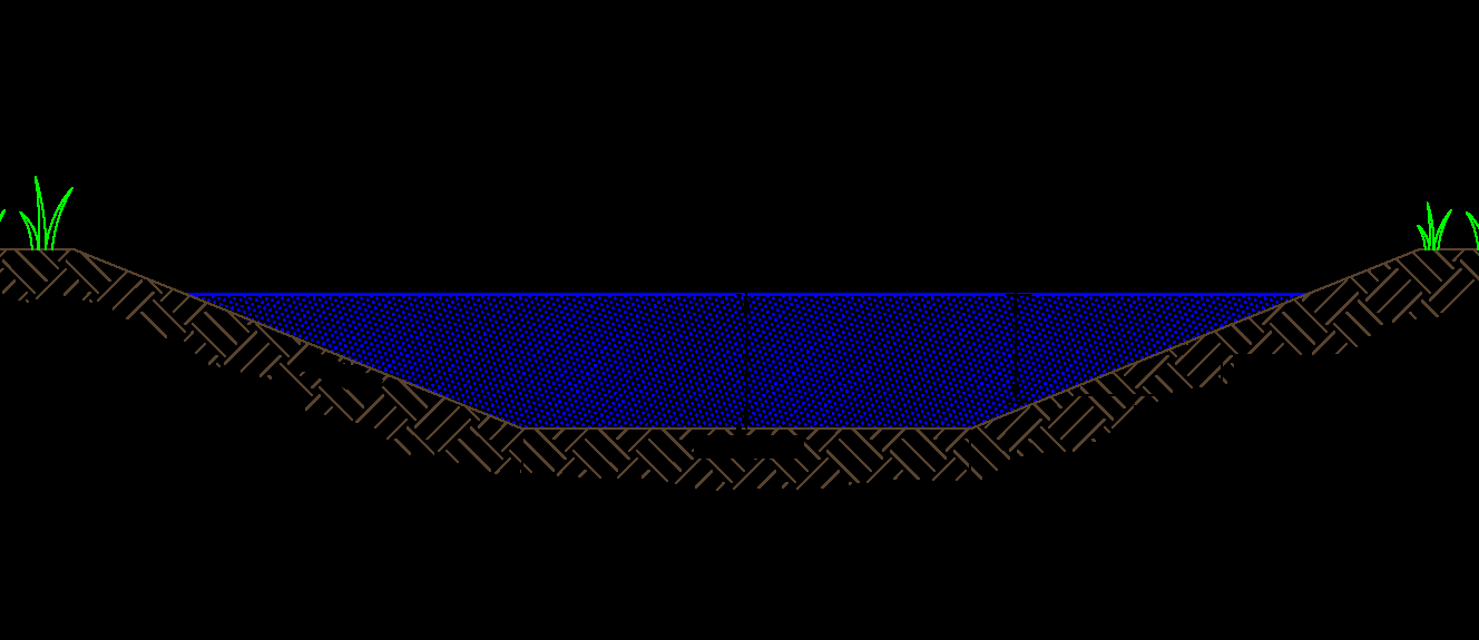
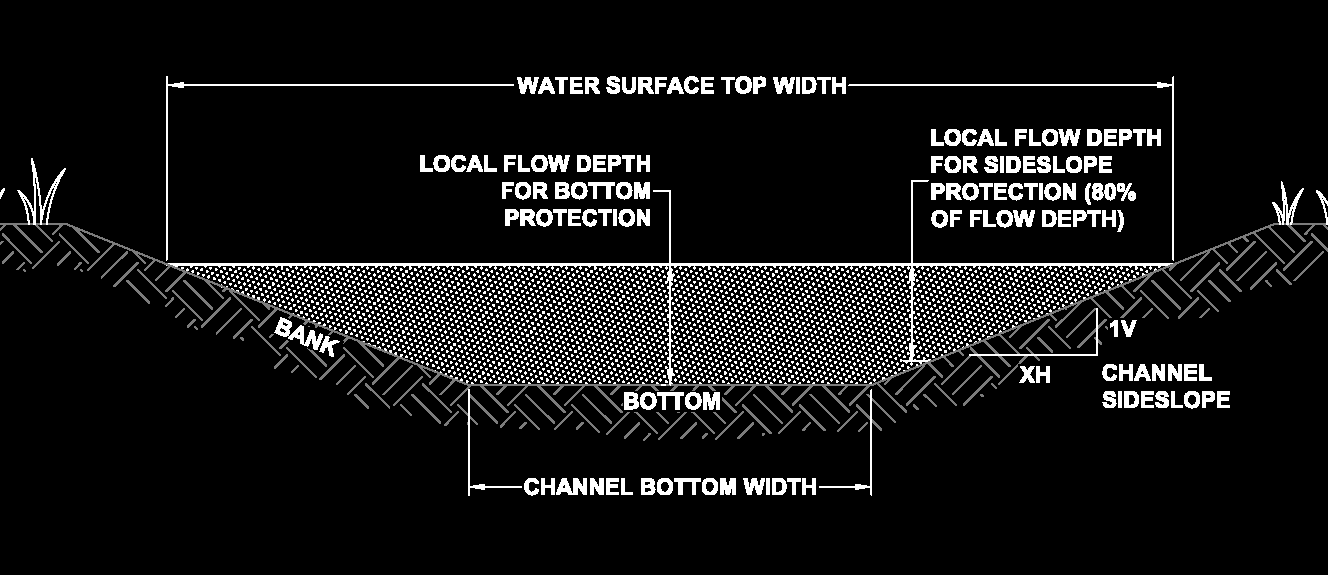
19 Determining Appropriate Rock Size Calculate Tractive Force Determine Permissible Tractive Force maximum unit tractive force that will not cause serious erosion of the material forming the channel bed on a level surface If tractive force is greater than permissible tractive force, erosion occurs use bigger rock Erosion Resistance Depends on: stone shape, size, weight, and durability; riprap gradation and layer thickness; channel alignment, crosssection, gradient, and velocity distribution (USACE, 1994)
20 Methods Determining Appropriate Rock Size Charts and Tables Programs & Spreadsheets E.g. Riprap Design System Washington Spillway Spreadsheets
21
22 Filter Layer Concepts A filter is a transitional layer of gravel, small stone, or fabric placed between the underlying soil and the structure. (HEC-11) The purpose of a filter Prevents the migration of fine soil particles through voids Distributes the weight of the armor units, causing more uniform settlement Permits relief of hydrostatic pressures within the soils For areas above water line, prevents surface water from causing erosion beneath the riprap
23 Filter Layer Concepts When should a filter be used? Whenever the riprap is placed on fine grained material subject to significant subsurface drainage Proper design is critical to bank riprap stability If filter openings are too large, excessive flow piping through the filter can cause erosion and failure of bank material below filter. If filter openings are too small, the build-up of hydrostatic pressures behind the filter can cause a slip plane to form along the filter, causing a translational slide failure
24 Gradation of filter layer Filtration Criteria Filter Layer Concepts D 15filter /D 85soil should be less than 5 to assure adequate filtration/retention Permeability Criteria D 15filter /D 15soil should be above 5 to assure adequate permeability/drainage Uniformity Criteria D 15filter /D 15soil should be less than 40 to assure adequate uniformity D 50filter /D 50soil should be less than 25 to assure adequate uniformity* *additional retention/uniformity criteria for drainage filters by USBR & COE

25 Application of Different Methods Summary of Filter Design D 15coarse /D 85fine < 5 < D 15coarse /D 15fine < 40
26 Filter Layer Concepts Other Filter Design Parameters Filters should be clean less than 5 to 10% fines Ideally, gradation curves for riprap and filters should be parallel Thickness of Filter Layer Single layer 6 to 15 inches Multiple layers 4 to 8 inches (each individual layer) Multiply by 1.5 for underwater placement Personal Opinion Rather than multiple layers to transition between coarse riprap and fine grained bank can often justify thicker layer (say 24 ) of well-graded pit run sandy gravel with cobbles some natural armoring of the outer layer occurs as fines wash away from uppermost layer under the riprap
27 Geotextile Filters Cheaper Filter Layer Concepts Acceptable for smaller riprap, especially with significant thickness of riprap layer Sometimes used as one part of a two part filter this is fairly efficient Vulnerable to tearing with large riprap don t drop rock Not uniform support for protected soil on steep slopes especially with large riprap (sometimes there is soil movement under the geotextile) Difficult to impossible to place under water, especially if in current

28
29 Specifying Riprap Gradations & Thicknesses Specifying rock weight is alternative to gradation Three-point gradations are common D 100, D 50, D 15 W 100, W 50, W 15
30 Specifying Riprap Gradations & Thicknesses

31 Specifying Riprap Gradations & Thicknesses USACE Gradations USACE Gradations shown for rock with a unit weight equal to 155 pcf Gradations shown below were developed for riprap placement in the dry, for low turbulence zones

32 Specifying Riprap Gradations & Thicknesses FHWA Gradations Assumes a specific gravity of 2.65 Based on AASHTO guidelines
33 Specifying Riprap Gradations & Thicknesses Thickness Guidelines and Constraints Normal range is 1.0 to 2.0 Thickness greater than 1.0 may allow a reduction in stone size due to increased layer thickness HEC-11 Guidance All stones should be contained reasonably well within the riprap layer thickness Should not be less than D 100 stone or less than 1.5 times D 50 stone Should not be less than 12 inches for practical placement Should increase thickness by 50% for underwater placement Should increase thickness by 6-12 inches where riprap will be subject to floating debris, ice, waves, wind, or bedforms

34
35 Other Design Considerations Material Quality Rock riprap preferred Broken concrete and other rubble must control material quality and gradation Shape neither the width or thickness of a stone should be less than 1/3 the length Consider rock density denser is better Angular rock is better than rounded Edge Treatment Toe extend below scour depth Flanks Smooth hydraulic profile at edges is important Bank Slope 2H:1V maximum
36 Placement Other Design Considerations Hand and machine placing Expensive Allows for steeper side slopes Dumping segregation and breakage can occur Longitudinal Extent Dependent on site conditions HEC-11 provides some guidance
37 Design Height Consider Other Design Considerations Wave action for impinging flow Design discharge and water level Superelevation in bends Hydraulic jumps Freeboard desired Ice Damage Crushing, impact loading, shearing forces Potentially increase stability factor if location has historic ice problems

38
39 Examples Basic Specifications for Riprap Montana Department of Transportation Standard Specifications for Road and Bridge Construction, 2006 Edition. Federal Highway Administration Hydraulic Engineering Circular No. 11 Design of Riprap Revetment, March 1989.
40 Basic Specifications for Riprap MDT Riprap Material Specifications Furnish stone that is hard, durable, and angular in shape, resistant to weathering and water action, free from overburden, spoil, shale, structural defects, and organic material. Each stone must have its greatest dimension not greater than three times its least dimension. Do not use rounded stone or boulders from a streambed source as riprap. Do not use shale or stone with shale seams.
41 Basic Specifications for Riprap HEC-11 Riprap Material Specifications Stone shall be hard, durable, angular in shape; resistant to weathering and water action; free from overburden, spoil, shale, and organic material. Neither breadth nor thickness of a stone shall be less than one-third of its length. Minimum unit weight shall be 155 lb/ft 3 LA Abrasion Test: no more than 40% loss
42
43 Application of Different Methods USACE Method For flow in manmade or natural channels having low turbulence and slopes less than 2% (spillways generally won t qualify) Bed or Bank
44 Application of Different Methods ASCE Method Uses Isbash equation with a modification to account for channel bank slope. Bed or Bank
45 Application of Different Methods USBR Method Developed for estimating riprap size downstream of a stilling basin Procedure developed using eleven prototype installations with velocity varying from 1 fps to 18 fps.
46 Application of Different Methods USGS Method Equation resulted from field data taken from WA, OR, CA, NV, and AZ. Survey related hydraulic conditions to performance of riprap protection. Surveys included 39 events of which 22 resulted in no riprap change. Of the 17 remaining events, 14 failures were caused by particle erosion.
47 Application of Different Methods Isbash Method Developed for the construction of dams by depositing rock into running water. Turbulence level (low or high) is factored into equation.
48 Application of Different Methods Cal B & SP Method CA Dept. of Transportation developed this method to protect highway embankments. Riprap embankments consist of one or more layers of rock. Accounts for different types of flow (impinging or parallel) by modifying the average channel velocity
49 Application of Different Methods HEC-11 Method Developed for use in rivers or streams with non-uniform flow conditions and discharges normally greater than 50 cfs. Bed or Bank
50 Application of Different Methods

51

52 Smith Lake Dam Examples Smith Lake Dam Located north of Whitefish Lake in Flathead County, Montana Problem Input Washington Spillway Calculations Riprap Design System
53 Examples Smith Lake Dam Problem Input Dam height = 11 feet No low-level outlet Trapezoidal principal spillway channel Length = 200 feet Design flow = 500 year = 143 cfs Crest channel slope = ft/ft bottom width = 15 ft Drop channel slope = ft/ft bottom width = 10 ft
54 Application of Different Methods
55 Examples Smith Lake Dam Smith Lake Dam (cont.) Comparison of RDS to WA spreadsheets (Bank)

56 Examples Teton Creek Teton Creek Stream Restoration Located in Teton County, Idaho
57 Examples Teton Creek Teton Creek (continued) Problem Input Q = 2050 cfs n = Slope = ft/ft Channel & inset floodplain Ch. btm width = 40 feet Inset FP side slope = 2:1 Riprap Design System Comparison with project gradation Bank protection at inset floodplain margin
58 Examples Teton Creek Teton Creek (cont.) Riprap Design System 160 pcf vs. 140 pcf riprap (USACE Method results shown)
 Riprap Design System Thickness Comparison (for results")
59 Examples Teton Creek Teton Creek (cont.) Riprap Design System Thickness Comparison (for results shown, γ = 140 pcf)
60 Examples Teton Creek Teton Creek (cont.) Riprap Design System Thickness Comparison (for results shown, γ = 140 pcf)

61 Examples Clearwater Clearwater River Fish Barrier Removal Located in Missoula County, Montana
62 Examples Clearwater

63 Examples - Clearwater Plan View of Numbered Rocks Profile
64 Clearwater (cont.) Problem Input Examples - Clearwater Total Q100 = 2250 cfs Q for channel = 1716 cfs Q for spillway = 534 cfs (spillway crest set 2.5 feet above channel spill) N = 0.09 Riffle slope = 0.03 ft/ft Riprap Design System Comparison with project gradation
65 Clearwater (cont.) Fish Passage Channel Examples - Clearwater Design Flow approx. 20 cfs Challenges Preventing subsurface flow Stability design flow vs. fish passage design low flow Tolerance for rock placement (>42 inch rock)

66
RIPRAP From Massachusetts Erosion and Sediment Control Guidelines for Urban and Suburban Areas http://www.mass.gov/dep/water/laws/policies.
 RIPRAP From Massachusetts Erosion and Sediment Control Guidelines for Urban and Suburban Areas http://www.mass.gov/dep/water/laws/policies.htm#storm Definition: A permanent, erosion-resistant ground cover
Emergency Spillways (Sediment basins)
") Emergency Spillways (Sediment basins) DRAINAGE CONTROL TECHNIQUE Low Gradient Velocity Control Short-Term Steep Gradient Channel Lining Medium-Long Term Outlet Control Soil Treatment Permanent [1] [1]
Emergency Spillways (Sediment basins) DRAINAGE CONTROL TECHNIQUE Low Gradient Velocity Control Short-Term Steep Gradient Channel Lining Medium-Long Term Outlet Control Soil Treatment Permanent [1] [1]
Design of Riprap Revetment HEC 11 Metric Version
 Design of Riprap Revetment HEC 11 Metric Version Welcome to HEC 11-Design of Riprap Revetment. Table of Contents Preface Tech Doc U.S. - SI Conversions DISCLAIMER: During the editing of this manual for
Open Channel Flow 2F-2. A. Introduction. B. Definitions. Design Manual Chapter 2 - Stormwater 2F - Open Channel Flow
 Design Manual Chapter 2 - Stormwater 2F - Open Channel Flow 2F-2 Open Channel Flow A. Introduction The beginning of any channel design or modification is to understand the hydraulics of the stream. The
CITY UTILITIES DESIGN STANDARDS MANUAL
 CITY UTILITIES DESIGN STANDARDS MANUAL Book 2 (SW) SW9 June 2015 SW9.01 Purpose This Chapter provides information for the design of open channels for the conveyance of stormwater in the City of Fort Wayne.
Appendix 4-C. Open Channel Theory
 4-C-1 Appendix 4-C Open Channel Theory 4-C-2 Appendix 4.C - Table of Contents 4.C.1 Open Channel Flow Theory 4-C-3 4.C.2 Concepts 4-C-3 4.C.2.1 Specific Energy 4-C-3 4.C.2.2 Velocity Distribution Coefficient
Riprap-lined Swale (RS)
") Riprap-lined Swale (RS) Practice Description A riprap-lined swale is a natural or constructed channel with an erosion-resistant rock lining designed to carry concentrated runoff to a stable outlet. This
Riprap-lined Swale (RS) Practice Description A riprap-lined swale is a natural or constructed channel with an erosion-resistant rock lining designed to carry concentrated runoff to a stable outlet. This
Topic 8: Open Channel Flow
 3.1 Course Number: CE 365K Course Title: Hydraulic Engineering Design Course Instructor: R.J. Charbeneau Subject: Open Channel Hydraulics Topics Covered: 8. Open Channel Flow and Manning Equation 9. Energy,
Outlet stabilization structure
 Overview of Sedimentation and Erosion Control Practices Practice no. 6.41 Outlet stabilization structure Erosion at the outlet of channels, culverts, and other structures is common, and can cause structural
Chapter 3 CULVERTS. Description. Importance to Maintenance & Water Quality. Culvert Profile
 Chapter 3 CULVERTS Description A culvert is a closed conduit used to convey water from one area to another, usually from one side of a road to the other side. Importance to Maintenance & Water Quality
Index. protection. excavated drop inlet protection (Temporary) 6.50.1 6.51.1. Block and gravel inlet Protection (Temporary) 6.52.1
 6.50.1 6.51.1. Block and gravel inlet Protection (Temporary) 6.52.1") 6 Index inlet protection excavated drop inlet protection (Temporary) 6.50.1 HARDWARE CLOTH AND GRAVEL INLET PROTECTION Block and gravel inlet Protection (Temporary) sod drop inlet protection ROCK DOUGHNUT
6 Index inlet protection excavated drop inlet protection (Temporary) 6.50.1 HARDWARE CLOTH AND GRAVEL INLET PROTECTION Block and gravel inlet Protection (Temporary) sod drop inlet protection ROCK DOUGHNUT
Welded Mesh Gabions and Mattresses River Protection Design Guide HY-TEN GABION SOLUTIONS Dunstall Hill Trading Estate, Gorsebrook Road,
 Welded Mesh Gabions and Mattresses River Protection Design Guide HY-TEN GABION SOLUTIONS Dunstall Hill Trading Estate, Gorsebrook Road, Wolverhampton, WV6 0PJ Tel 01902 712200 Fax 01902 714096 e-mail sales@hy-tengabions.com
2.0 BASIC CONCEPTS OF OPEN CHANNEL FLOW MEASUREMENT
 2.0 BASIC CONCEPTS OF OPEN CHANNEL FLOW MEASUREMENT Open channel flow is defined as flow in any channel where the liquid flows with a free surface. Open channel flow is not under pressure; gravity is the
How To Check For Scour At A Bridge
 Case Studies Bridge Scour Inspection and Repair Edward P. Foltyn, P.E. Senior Hydraulic Engineer ODOT Bridge Unit 2013 PNW Bridge Inspectors Conference April 2013 REFERENCES Stream Stability at Highway
Lecture 24 Flumes & Channel Transitions. I. General Characteristics of Flumes. Flumes are often used:
 Lecture 24 Flumes & Channel Transitions I. General Characteristics of Flumes Flumes are often used: 1. Along contours of steep slopes where minimal excavation is desired 2. On flat terrain where it is
CHAPTER 9 CHANNELS APPENDIX A. Hydraulic Design Equations for Open Channel Flow
 CHAPTER 9 CHANNELS APPENDIX A Hydraulic Design Equations for Open Channel Flow SEPTEMBER 2009 CHAPTER 9 APPENDIX A Hydraulic Design Equations for Open Channel Flow Introduction The Equations presented
Specification Guidelines: Allan Block Modular Retaining Wall Systems
 Specification Guidelines: Allan Block Modular Retaining Wall Systems The following specifications provide Allan Block Corporation's typical requirements and recommendations. At the engineer of record's
Lecture 22 Example Culvert Design Much of the following is based on the USBR technical publication Design of Small Canal Structures (1978)
") Lecture 22 Example Culvert Design Much of the following is based on the USBR technical publication Design of Small Canal Structures (1978) I. An Example Culvert Design Design a concrete culvert using the
Lecture 22 Example Culvert Design Much of the following is based on the USBR technical publication Design of Small Canal Structures (1978) I. An Example Culvert Design Design a concrete culvert using the
GEOSYNTHETICS ENGINEERING: IN THEORY AND PRACTICE
 GEOSYNTHETICS ENGINEERING: IN THEORY AND PRACTICE Prof. J. N. Mandal Department of civil engineering, IIT Bombay, Powai, Mumbai 400076, India. Tel.022-25767328 email: cejnm@civil.iitb.ac.in Module - 4
CHAPTER 5 OPEN CHANNEL HYDROLOGY
 5.4 Uniform Flow Calculations 5.4.1 Design Charts CHAPTER 5 OPEN CHANNEL HYDROLOGY Following is a discussion of the equations that can be used for the design and analysis of open channel flow. The Federal
1. Carry water under the canal 2. Carry water over the canal 3. Carry water into the canal
 Lecture 21 Culvert Design & Analysis Much of the following is based on the USBR publication: Design of Small Canal Structures (1978) I. Cross-Drainage Structures Cross-drainage is required when a canal
Guo, James C.Y. (2004). Design of Urban Channel Drop Structure, J. of Flood Hazards News, December,
. Design of Urban Channel Drop Structure, J. of Flood Hazards News, December,") Guo, James C.. (004). esign of Urban Channel rop Structure, J. of Flood azards News, ecember, Guo, James C.., (009) Grade Control for Urban Channel esign, submitted to Elsevier Science, J. of ydro-environmental
Guo, James C.. (004). esign of Urban Channel rop Structure, J. of Flood azards News, ecember, Guo, James C.., (009) Grade Control for Urban Channel esign, submitted to Elsevier Science, J. of ydro-environmental
SPECIFICATIONS FOR PRECAST MODULAR BLOCK RETAINING WALL SYSTEM (revised 11/5/13)
") Page 1 of 7 STONE STRONG SYSTEMS SPECIFICATIONS FOR PRECAST MODULAR BLOCK RETAINING WALL SYSTEM (revised ) PART 1: GENERAL 1.01 Description A. Work includes furnishing and installing precast modular blocks
Page 1 of 7 STONE STRONG SYSTEMS SPECIFICATIONS FOR PRECAST MODULAR BLOCK RETAINING WALL SYSTEM (revised ) PART 1: GENERAL 1.01 Description A. Work includes furnishing and installing precast modular blocks
BRIDGES ARE relatively expensive but often are
 Chapter 10 Bridges Chapter 10 Bridges Bridg Bridges -- usually the best, but most expensive drainage crossing structure. Protect bridges against scour. BRIDGES ARE relatively expensive but often are the
Scour and Scour Protection
 Design of Maritime Structures Scour and Scour Protection Steven A. Hughes, PhD, PE Coastal and Hydraulics Laboratory US Army Engineer Research and Development Center Waterways Experiment Station 3909 Halls
A perforated conduit such as pipe, tubing or tile installed beneath the ground to intercept and convey ground water. or structures.
 BMP: SUBSURFACE DRAIN Definition A perforated conduit such as pipe, tubing or tile installed beneath the ground to intercept and convey ground water. PurRoses 1. To prevent sloping soils from becoming
City of Shelbyville Site Inspection Checklist
 City of Shelbyville Site Inspection Checklist General Information Project Name: KYR10 Permit Number: Date: Project Location: Contractor: Conractor Representative: Inspector's Name: Title: Signature : Weather
STATE OF FLORIDA DEPARTMENT OF TRANSPORTATION DRAINAGE HANDBOOK OPEN CHANNEL. OFFICE OF DESIGN, DRAINAGE SECTION November 2009 TALLAHASSEE, FLORIDA
 STATE OF FLORIDA DEPARTMENT OF TRANSPORTATION DRAINAGE HANDBOOK OPEN CHANNEL OFFICE OF DESIGN, DRAINAGE SECTION TALLAHASSEE, FLORIDA Table of Contents Open Channel Handbook Chapter 1 Introduction... 1
2O-1 Channel Types and Structures
 Iowa Stormwater Management Manual O-1 O-1 Channel Types and Structures A. Introduction The flow of water in an open channel is a common event in Iowa, whether in a natural channel or an artificial channel.
CHAPTER 3 STORM DRAINAGE SYSTEMS
 CHAPTER 3 STORM DRAINAGE SYSTEMS 3.7 Storm Drains 3.7.1 Introduction After the tentative locations of inlets, drain pipes, and outfalls with tail-waters have been determined and the inlets sized, the next
Open channel flow Basic principle
 Open channel flow Basic principle INTRODUCTION Flow in rivers, irrigation canals, drainage ditches and aqueducts are some examples for open channel flow. These flows occur with a free surface and the pressure
Open Channel Flow in Aquaculture
 SRAC Publication No. 74 Southern Regional Aquaculture Center March 1995 PR VI Open Channel Flow in Aquaculture J. David Bankston, Jr. 1 and Fred Eugene Baker Open channel flow of water has been used in
Section 2100-Trenching and Tunneling
 SECTION 5200 - STORM SEWER PART 1 - GENERAL 1.01 SCOPE: This Section covers installation of storm sewer mains and culverts. Topics include permits and fees, trench widths, pipe laying, bedding, initial
Chapter 7 Ditches and Channels
 Chapter 7 Ditches and Channels TABLE OF CONTENTS CHAPTER 7 - DITCHES AND CHANNELS... 7-1 7.1 Introduction... 7-1 7.2 Design Policy... 7-2 7.2.1 Federal Policy... 7-2 7.2.2 Commonwealth of Virginia Policy...
M6a: Open Channel Flow (Manning s Equation, Partially Flowing Pipes, and Specific Energy)
") M6a: Open Channel Flow (, Partially Flowing Pipes, and Specific Energy) Steady Non-Uniform Flow in an Open Channel Robert Pitt University of Alabama and Shirley Clark Penn State - Harrisburg Continuity
M6a: Open Channel Flow (, Partially Flowing Pipes, and Specific Energy) Steady Non-Uniform Flow in an Open Channel Robert Pitt University of Alabama and Shirley Clark Penn State - Harrisburg Continuity
Part 7 GEOTEXTILE FILTER FABRICS
 Part 7 GEOTEXTILE FILTER FABRICS Well Screens Slotted casings are normally employed as well screens within the aquifers being taped by water wells. The width of the slots should allow 50 to 60% of the
Flash Flood Science. Chapter 2. What Is in This Chapter? Flash Flood Processes
 Chapter 2 Flash Flood Science A flash flood is generally defined as a rapid onset flood of short duration with a relatively high peak discharge (World Meteorological Organization). The American Meteorological
CHAPTER 2 HYDRAULICS OF SEWERS
 CHAPTER 2 HYDRAULICS OF SEWERS SANITARY SEWERS The hydraulic design procedure for sewers requires: 1. Determination of Sewer System Type 2. Determination of Design Flow 3. Selection of Pipe Size 4. Determination
Experiment (13): Flow channel
: Flow channel") Introduction: An open channel is a duct in which the liquid flows with a free surface exposed to atmospheric pressure. Along the length of the duct, the pressure at the surface is therefore constant and
Introduction: An open channel is a duct in which the liquid flows with a free surface exposed to atmospheric pressure. Along the length of the duct, the pressure at the surface is therefore constant and
6.0 Results of Risk Analyses
 6. Results of Risk Analyses A risk analysis of the optimized embankment designs for the Salton Sea restoration project was conducted jointly by Kleinfelder and representatives from Reclamation. A risk
Lecture 6. Jump as energy dissipation Control of jump.
 Lecture 6 Jump as energy dissipation Control of jump. Jump as energy dissipation The high energy loss that occurs in a hydraulic jump has led to its adoption as a part of high energy dissipater system
DRAINAGE CRITERIA MANUAL (V. 2) CULVERTS CONTENTS
 CULVERTS CONTENTS") DRAINAGE CRITERIA MANUAL (V. 2) CONTENTS Section Page CU 1.0 INTRODUCTION AND OVERVIEW... 1 1.1 Required Design Information... 3 1.1.1 Discharge... 4 1.1.2 Headwater... 4 1.1.3 Tailwater... 5 1.1.4 Outlet
DRAINAGE CRITERIA MANUAL (V. 2) CONTENTS Section Page CU 1.0 INTRODUCTION AND OVERVIEW... 1 1.1 Required Design Information... 3 1.1.1 Discharge... 4 1.1.2 Headwater... 4 1.1.3 Tailwater... 5 1.1.4 Outlet
Chapter 9. Steady Flow in Open channels
 Chapter 9 Steady Flow in Open channels Objectives Be able to define uniform open channel flow Solve uniform open channel flow using the Manning Equation 9.1 Uniform Flow in Open Channel Open-channel flows
Land Disturbance, Erosion Control and Stormwater Management Checklist. Walworth County Land Conservation Department
 Land Disturbance, Erosion Control and Stormwater Management Checklist Walworth County Land Conservation Department The following checklist is designed to assist the applicant in complying with the Walworth
Evaluation of Open Channel Flow Equations. Introduction :
 Evaluation of Open Channel Flow Equations Introduction : Most common hydraulic equations for open channels relate the section averaged mean velocity (V) to hydraulic radius (R) and hydraulic gradient (S).
SIENA STONE GRAVITY RETAINING WALL INSTALLATION SPECIFICATIONS. Prepared by Risi Stone Systems Used by permission.
 SIENA STONE GRAVITY RETAINING WALL INSTALLATION SPECIFICATIONS Prepared by Risi Stone Systems Used by permission. 1-800-UNILOCK www.unilock.com FOREWORD This outline specification has been prepared for
WEATHERING, EROSION, AND DEPOSITION PRACTICE TEST. Which graph best shows the relative stream velocities across the stream from A to B?
 NAME DATE WEATHERING, EROSION, AND DEPOSITION PRACTICE TEST 1. The diagram below shows a meandering stream. Measurements of stream velocity were taken along straight line AB. Which graph best shows the
Watershed Works Manual
 National Rural Employment Guarantee Act Watershed Works Manual DRAINAGE LINE TREATMENT: GABION STRUCTURE Baba Amte Centre for People s Empowerment Samaj Pragati Sahayog September 2006 Drainage Line Treatment:
NJ650.1404 Interception Drainage
 NJ650.1404 Interception Drainage Interception drainage is used to intercept surface and subsurface water. The investigation, planning, and construction of surface interception drains follow the requirements
Broad Crested Weirs. I. Introduction
 Lecture 9 Broad Crested Weirs I. Introduction The broad-crested weir is an open-channel flow measurement device which combines hydraulic characteristics of both weirs and flumes Sometimes the name ramp
Basic Principles of Channel Design
 United States Department of Agriculture Natural Resources Conservation Service Stream Restoration Design Chapter 7 Basic Principles of Channel Design Issued August 2007 Cover photo: Where modification
Design Charts for Open-Channel Flow HDS 3 August 1961
 Design Charts for Open-Channel Flow HDS 3 August 1961 Welcome to HDS 3-Design Charts for Open-Channel Flow Table of Contents Preface DISCLAIMER: During the editing of this manual for conversion to an electronic
Table 4.9 Storm Drain Inlet Protetion Applicable for
 BMP C220: Storm Drain Inlet Protection Purpose To prevent coarse sediment from entering drainage systems prior to permanent stabilization of the disturbed area. Conditions of Use Type of Inlet Protection
What is the most obvious difference between pipe flow and open channel flow????????????? (in terms of flow conditions and energy situation)
") OPEN CHANNEL FLOW 1 3 Question What is the most obvious difference between pipe flow and open channel flow????????????? (in terms of flow conditions and energy situation) Typical open channel shapes Figure
OPEN CHANNEL FLOW 1 3 Question What is the most obvious difference between pipe flow and open channel flow????????????? (in terms of flow conditions and energy situation) Typical open channel shapes Figure
Objectives and Purpose...Page 1 Open Bottom Arch - Flow Model...Page 1 The Pros and Cons of Metal Arch Culverts...Page 2 Positive Features of Arch
 Objectives and Purpose...Page 1 Open Bottom Arch - Flow Model...Page 1 The Pros and Cons of Metal Arch Culverts...Page 2 Positive Features of Arch Culverts....Page 2 Negative features of Arch Culverts...Page
USE OF GEOSYNTHETICS FOR FILTRATION AND DRAINAGE
 USE OF GEOSYNTHETICS FOR FILTRATION AND DRAINAGE Prof. G L Sivakumar Babu Department of Civil Engineering Indian Institute of Science Bangalore 560012 Functions of a Filter Retain particles of the base
SECTION 5 - STORM DRAINS
 Drainage Criteria Manual SECTION 5 - STORM DRAINS 5.1.0 GENERAL This The purpose of this section discusses briefly is to consider the hydraulic aspects of storm drains and their appurtenances in a storm
Managing Our Water Retention Systems
 Managing Our Water Retention Systems 29th Annual USSD Conference Nashville, Tennessee, April 20-24, 2009 Hosted by Corps of Engineers On the Cover Wolf Creek Dam is on the Cumberland River in South Central
GLOSSARY OF TERMS CHAPTER 11 WORD DEFINITION SOURCE. Leopold
 CHAPTER 11 GLOSSARY OF TERMS Active Channel The channel that contains the discharge Leopold where channel maintenance is most effective, sediment are actively transported and deposited, and that are capable
DESIGN GUIDELINES FOR EARTH RETENTION
 DESIGN GUIDELINES FOR EARTH RETENTION Strata Systems, Inc. 380 Dahlonega Rd., Suite 200 Cumming, GA 30040 USA www.geogrid.com TABLE OF CONTENTS MECHANICS OF RETAINING WALLS... 3 THE STRATAWEB SOLUTION...4
Basic Hydrology. Time of Concentration Methodology
 Basic Hydrology Time of Concentration Methodology By: Paul Schiariti, P.E., CPESC Mercer County Soil Conservation District What is the Time of Concentration? The time it takes for runoff to travel from
SECTION 31 20 00 EARTH MOVING
 SECTION 31 20 00 PART 1 - GENERAL 1.01 DESCRIPTION A. This Section describes the requirements for excavating, filling, and grading for earthwork at Parking Structure, new exit stair and as required to
METHOD OF TEST FOR DETERMINATION OF PERMEABILITY OF GRANULAR SOILS
 Laboratory Testing Manual Date: 99 06 21 Page 1 of 7 METHOD OF TEST FOR DETERMINATION OF PERMEABILITY OF GRANULAR SOILS 1. SCOPE 1.1 This method covers the determination of the coefficient of permeability
CHAPTER 860 OPEN CHANNELS
 HIGHWAY DESIGN MANUAL 860-1 CHAPTER 860 OPEN CHANNELS Topic 861 - General Index 861.1 - Introduction An open channel is a conveyance in which water flows with a free surface. Although closed conduits such
Module 7 (Lecture 24 to 28) RETAINING WALLS
 RETAINING WALLS") Module 7 (Lecture 24 to 28) RETAINING WALLS Topics 24.1 INTRODUCTION 24.2 GRAVITY AND CANTILEVER WALLS 24.3 PROPORTIONING RETAINING WALLS 24.4 APPLICATION OF LATERAL EARTH PRESSURE THEORIES TO DESIGN 24.5
Module 7 (Lecture 24 to 28) RETAINING WALLS Topics 24.1 INTRODUCTION 24.2 GRAVITY AND CANTILEVER WALLS 24.3 PROPORTIONING RETAINING WALLS 24.4 APPLICATION OF LATERAL EARTH PRESSURE THEORIES TO DESIGN 24.5
Construction Site Inspection Checklist for OHC000004 By making use of some simple Best Management Practices (BMPs) a construction site operator can
 a construction site operator can") Construction Site Inspection Checklist for OHC000004 By making use of some simple Best Management Practices (BMPs) a construction site operator can do his or her share to protect Ohio's water resources
Construction Site Inspection Checklist for OHC000004 By making use of some simple Best Management Practices (BMPs) a construction site operator can do his or her share to protect Ohio's water resources
Lecture 17 Design of Earthen Canals. I. General
 Lecture 17 Design of Earthen Canals I. General Much of this information applies in general to both earthen and lined canals Attempt to balance cuts and fills to avoid waste material and or the need for
Final. Contact person: Colin Whittemore Aurecon Centre 1 Century City Drive Waterford Precinct, Century City Cape Town, South Africa
 Review Report and Recommendations for the Remediation of Flood Damage at the Berg River Causeway and the Dam Bypass Channel on Portion of Farms 1646 and 1014, Franschhoek Contact person: Colin Whittemore
2011 HYDRAULICS MANUAL
 STATE OF LOUISIANA DEPARTMENT OF TRANSPORTATION AND DEVELOPMENT P.O. Box 94245 Baton Rouge, Louisiana 70804-9245 http://www.dotd.la.gov/ HYDRAULICS MANUAL Hydraulics (225) 379-1306 PREFACE The following
3. Design Procedures. Design Procedures. Introduction
 Design Procedures 3. Design Procedures Introduction This chapter presents a procedure for the design of natural channels. The chapter primarily focuses on those physical properties of the channel required
WEATHERING, EROSION, and DEPOSITION REVIEW
 WEATHERING, EROSION, and DEPOSITION REVIEW Weathering: The breaking up of rock from large particles to smaller particles. a) This Increases surface area of the rock which speeds the rate of chemical weathering.
A Stream Restoration Case Study in the California Central Coast
 International Erosion Control Association Annual Conference 2009, Reno, Nevada Case Study Technical Presentation A Stream Restoration Case Study in the California Central Coast Justin S. Rogers, P.E.,
geotextile filter design, application, and product selection guide
 geotextile filter design, application, and product selection guide Marine & Transportation Engineering TC Mirafi MIRAFI GEOTEXTILE FILTER DESIGN, APPLICATION, AND PRODUCT SELECTION GUIDE Drainage and Erosion
STORM DRAINS CHAPTER 7
 CHAPTER 7 Chapter 7 - Storm Drains A storm drain is a drainage system that conveys water or stormwater, consisting of two or more pipes in a series connected by one or more structures. Storm drains collect
June 2007 CHAPTER 7 - CULVERTS 7.0 CHAPTER 7 - CULVERTS 7.1 GENERAL
 7.0 7.1 GENERAL For the purpose of this manual, culverts are defined as structures that are completely surrounded by soil and located below the surface of the roadway parallel to the general direction
CHAPTER 11 ENERGY DISSIPATORS
 CHAPTER 11 ENERGY DISSIPATORS TABLE OF CONTENTS 11.1 INTRODUCTION...2 11.2 DESIGN CRITERIA...2 11.2.1 Dissipator Type Selection...2 11.2.2 Design Limitations...5 11.2.3 Design Options...5 11.2.4 Related
CHAPTER 7 DRAINAGE OF PAVEMENTS
 CHAPTER 7 DRAINAGE OF PAVEMENTS 7-1. Drainage control Adequate drainage of surface and ground water is one of the most important considerations in the design, construction, and maintenance of roads, railroads,
Safe & Sound Bridge Terminology
 Safe & Sound Bridge Terminology Abutment A retaining wall supporting the ends of a bridge, and, in general, retaining or supporting the approach embankment. Approach The part of the bridge that carries
Block and Gravel Inlet Protection (BIP)
") Block and Gravel Inlet Protection (BIP) Practice Description Block and gravel inlet protection is a sediment control barrier formed around a storm drain inlet by the use of standard concrete block and
Block and Gravel Inlet Protection (BIP) Practice Description Block and gravel inlet protection is a sediment control barrier formed around a storm drain inlet by the use of standard concrete block and
Travel Time. Computation of travel time and time of concentration. Factors affecting time of concentration. Surface roughness
 3 Chapter 3 of Concentration and Travel Time Time of Concentration and Travel Time Travel time ( T t ) is the time it takes water to travel from one location to another in a watershed. T t is a component
OPEN-CHANNEL FLOW. Free surface. P atm
 OPEN-CHANNEL FLOW Open-channel flow is a flow of liquid (basically water) in a conduit with a free surface. That is a surface on which pressure is equal to local atmospheric pressure. P atm Free surface
MIKE 21 FLOW MODEL HINTS AND RECOMMENDATIONS IN APPLICATIONS WITH SIGNIFICANT FLOODING AND DRYING
 1 MIKE 21 FLOW MODEL HINTS AND RECOMMENDATIONS IN APPLICATIONS WITH SIGNIFICANT FLOODING AND DRYING This note is intended as a general guideline to setting up a standard MIKE 21 model for applications
SECTION 5. Sediment Control Measures
 SECTION 5 Sediment Control Measures 60. STORM DRAIN INLET PROTECTION When Runoff from earth change activities will discharge to a catch basin or storm drain inlet. A newly constructed catch basin or storm
ROSE CREEK WATERSHED HYDROLOGIC, HYDRAULIC, SEDIMENT TRANSPORT, AND GEOMORPHIC ANALYSES TASK 1 EXISTING DATA AND INFORMATION SUMMARY REPORT BACKGROUND
 ROSE CREEK WATERSHED HYDROLOGIC, HYDRAULIC, SEDIMENT TRANSPORT, AND GEOMORPHIC ANALYSES TASK 1 EXISTING DATA AND INFORMATION SUMMARY REPORT BACKGROUND The Rose Creek Watershed (RCW) consists of three planning
ANNEX D1 BASIC CONSIDERATIONS FOR REVIEWING STUDIES IN THE DETAILED RISK ASSESSMENT FOR SAFETY
 ANNEX D1 BASIC CONSIDERATIONS FOR REVIEWING STUDIES IN THE DETAILED RISK ASSESSMENT FOR SAFETY ANNEX D1: BASIC CONSIDERATIONS FOR REVIEWING STUDIES IN DRA FOR SAFETY D1-1 ANNEX D1 BASIC CONSIDERATIONS
Jackson Gulch Outlet Canal Rehabilitation Project
 Jackson Gulch Outlet Canal Rehabilitation Project Preliminary Budgetary Estimate for Rehabilitation February 2004 Prepared for the Mancos Water Conservancy District Jackson Gulch Reservoir 42888 County
Pima RDstiChannel DesiggSubmittal
 CTY OF SCOTTSDALE DESERT GREENBELT PROJECT Pima RDstiChannel DesiggSubmittal by: The Greiner Team May 1995 VOLUME V 1 [, ~. r. r (, - e. ( - CTY OF SCOTTSDALE DESERT GREENBELT PROJECT Manninlfs Hn //
TENNESSEE GAS PIPELINE COMPANY, L.L.C.
 TENNESSEE GAS PIPELINE COMPANY, L.L.C. HYDROLOGIC & HYDRAULIC CALCULATIONS FOR WATERBODIES CROSSED BY CONNECTICUT PIPELINE EXPANSION PROJECT CONNECTICUT LOOP Submitted by: Tennessee Gas Pipeline Company,
Minimizes sediment and debris from entering storm drains that lead to waterways and watercourses.
 4.5-p DRAIN INLET PROTECTION Alternative Names: DI protection, Drop Inlet Protection DESCRIPTION Storm drain inlet (DI) protection slows and ponds stormwater, and filters sediment and debris before it
Stormwater/Wetland Pond Construction Inspection Checklist
 : Construction Inspection ChecklistsTools Stormwater/Wetland Pond Construction Inspection Checklist Project: Location: Site Status: Date: Time: Inspector: SATISFACTORY/ UNSATISFACTORY COMMENTS Pre-Construction/Materials
UNDER DRAINAGE AND FILTER DESIGN
 UNDER DRAINAGE AND FILTER DESIGN Tailings and HLP Workshop 28 April to 1 May 2010 INTRODUCTION The internal drainage is of crucial importance to the reliability and safety of a tailings dam throughout
Hydraulic Jumps and Non-uniform Open Channel Flow, Course #507. Presented by: PDH Enterprises, LLC PO Box 942 Morrisville, NC 27560 www.pdhsite.
 Hydraulic Jumps and Non-uniform Open Channel Flow, Course #507 Presented by: PDH Enterprises, LLC PO Box 942 Morrisville, NC 27560 www.pdhsite.com Many examples of open channel flow can be approximated
SANITARY SEWER SPECIFICATIONS
 SANITARY SEWER SPECIFICATIONS OCTOBER 2003 HARVEST-MONROVIA WATER, SEWER, AND FIRE PROTECTION AUTHORITY SECTION 1.00 1.10 Purpose The purpose of this document is to assemble the sewer specifications, policies,
CONFIRMING WET WEATHER TREATMENT FACILITY HYDRAULIC DESIGN WITH PHYSICAL MODEL STUDY
 CONFIRMING WET WEATHER TREATMENT FACILITY HYDRAULIC DESIGN WITH PHYSICAL MODEL STUDY TONY YEE, PE JARED HUTCHINS, PE METROPOLITAN SEWER DISTRICT OF GREATER CINCINNATI BLACK & VEATCH WET WEATHER TREATMENT
Crossing creeks Stream crossings on farms
 Crossing creeks Stream crossings on farms Looking after all our water needs Crossing creeks Stream crossings on farms Looking after all our water needs Department of Water 168 St Georges Terrace Perth
CHAPTER 4 STORM DRAINAGE SYSTEMS
 CHAPTER 4 STORM DRAINAGE SYSTEMS 4.1 Overview... 4-1 4.1.1 Introduction... 4-1 4.1.2 Inlet Definition... 4-1 4.1.3 Criteria... 4-1 4.2 Pavement Drainage... 4-2 4.2.1 Introduction... 4-2 4.2.2 Storm Drain
Division 2 Section 32 14 13.19 Section 02795
 Note: The text must be edited to suit specific project requirements. It should be reviewed by a qualified civil or geotechnical engineer, or landscape architect familiar with the site conditions. Edit
PART 3 DEFINITION OF ROCKFILL VERSUS EARTHFILL MATERIAL
 PART 3 DEFINITION OF ROCKFILL VERSUS EARTHFILL MATERIAL Allan J. Breitenbach, P.E. AB Engineering Inc. Littleton, Colorado, USA Telephone: 1/720-981-5244 Telefax: 1/720-981-5245 Email: ajbreitenbach@hotmail.com
PERFORMANCE OF FLOOD-TESTED SOIL-CEMENT PROTECTED LEVEES. Kenneth D. Hansen, P.E. 1 Dennis L. Richards, P.E. 2 Mark E. Krebs, P.E.
 PERFORMANCE OF FLOOD-TESTED SOIL-CEMENT PROTECTED LEVEES Kenneth D. Hansen, P.E. 1 Dennis L. Richards, P.E. 2 Mark E. Krebs, P.E. 3 ABSTRACT Although there were some early projects using soil-cement to
Sand and Silt Removal from Salmonid Streams
 Sand and Silt Removal from Salmonid Streams Stream bank erosion Poor land use practices Sources of Sand and Silt Impacts of Sand and Silt Interstitial spaces infilled Little or no flow through the streambed